

Page 1
BMG7011 and BMG7012
Broadband Media Gateway
User’s Guide
Oki Network Technologies
Revision 1.9 Preliminary
Page 2

Document Revision History
Title:
Document No.:
Author:
BMG7011 and BMG7012 Broadband Media Gateway User’s Guide
P/N BMG12-UG
Oki Network Technologies
Revision # Revision Date Reason for Update Updated by:
0.9 11/22/03 First draft J. Yaya
1.3 11/29/03 Corrections and additions J. Yaya
1.5 11/21/03 Screen Cap Updates M.Rosenbaum
1.6 12/2/03 Corrections and additions J. Yaya
1.7 12/10/03 Corrections and additions M. Rosenbaum
1.8 3/18/04 Corrections and additions
1.8 4/12/04 Corrections to Text M.Rosenbaum
1.9 4/14/04 Addition of Improved Installation Procedures Z. Mohseni, M. Rosenbaum
i
Page 3

Copyrights Notice
The BMG7011 and BMG7012 Broadband Media Gateways are products of Oki Network Technologies
Rights to reproduce this manual are restricted by the Copyright{ XE "Copyright" } Act.
No part of this document may be reproduced, stored on a retrieval system, or transmitted in any form by any means, electronic,
mechanical, imaging, recording or otherwise, without the express written permission of Oki Network Technologies.
Information in this document is subject to change without notice.
The contents of this document have been prepared with the utmost care. However, if you should notice an ambiguous point or
omission, please contact an authorized agent. Oki Network Technologies assumes no responsibility with respect to consequences
resulting from the use of these products and/or the content and interpretation of the information contained in this manual.
2004, Oki Network Technologies. All rights reserved.
First edition: November 2003
Ethernet is a registered trademark of Xerox Corporation. Other companies and product names mentioned in this manual are the
registered trademarks or services of their respective companies.
Revision 1.8
© Copyright, 2004 Oki Network Technologies. All Rights Reserved
ii
Page 4

Contents
1. OVERVIEW.......................................................................................................................................................1
1.1 P
ACKAGE CONTENTS
...................................................................................................................................1
1.2 SYSTEM REQUIREMENTS .............................................................................................................................1
1.3 FEATURES ....................................................................................................................................................1
2. HARDWARE INSTALLATION.......................................................................................................................3
2.1 F
RONT VIEW
(LEDS)...................................................................................................................................3
2.2 REAR VIEW (PORTS) ....................................................................................................................................4
2.3 INITIAL INSTALLATION PROCEDURES FOR ADSL AND CABLE NETWORKS.................................................5
2.3.1 Configuring TCP/IP Protocol for Your PC .............................................................................................5
2.4 C
ONFIGURING THE
BMG7011
BMG7012 VOIP
AND
GATEWAYS
...............................................................6
2.4.1 Configuring via Web Browser.................................................................................................................6
2.4.2 Setting your BMG to communicate through PPPoE...............................................................................7
2.4.3 Setting your BMG to communicate through DHCP................................................................................9
2.4.4 Setting your BMG to communicate through a Static IP address........................................................... 11
2.5 I
NSTALLATION OVERVIEW FOR
ADSL
AND CABLE NETWORKS
...............................................................12
3. STATUS ............................................................................................................................................................15
3.1.1 System Status: .......................................................................................................................................15
3.1.2 Port Status: ...........................................................................................................................................16
3.1.3 DHCPC Status:.....................................................................................................................................17
3.1.4 PPPoE Status:.......................................................................................................................................18
3.1.5 PPPoE Configuration:..........................................................................................................................19
3.2 DHCP SERVER CONFIGURATION ...............................................................................................................20
3.2.1 DHCP Configuration ............................................................................................................................20
3.3 WAN CONFIGURATION..............................................................................................................................21
3.3.1 WAN IP .................................................................................................................................................21
3.3.2 Remote Provisioning.............................................................................................................................22
3.3.3 Device Mode .........................................................................................................................................23
3.4 NTP ...........................................................................................................................................................24
3.4.1 NTP .......................................................................................................................................................24
3.5 NAPT CONFIGURATION ............................................................................................................................25
3.5.1 Port Forwarding ...................................................................................................................................25
3.5.2 IP Filtering............................................................................................................................................26
3.5.3 DMZ ......................................................................................................................................................27
3.6 QOS ...........................................................................................................................................................28
3.6.1 QoS Configuration ................................................................................................................................28
3.6.2 DSCP Configuration.............................................................................................................................29
3.6.3 VLan Configuration ..............................................................................................................................30
3.7 MAC CLONING...........................................................................................................................................31
3.8 PSTN CONFIGURATION .............................................................................................................................32
iii
Page 5

Switch Key.............................................................................................................................................32
3.8.1
3.8.2 Digit Map..............................................................................................................................................33
3.9
3.10 SYSLOG CONFIGURATION ..........................................................................................................................35
3.11 EMS CONFIGURATION...............................................................................................................................36
3.12 VOIP CONFIGURATION ..............................................................................................................................39
3.13 PASSWORD CONFIGURATION .....................................................................................................................57
3.14 UPGRADE CONFIGURATION .......................................................................................................................59
3.15 SAV E ..........................................................................................................................................................61
PROVISION CONFIGURATION .....................................................................................................................34
3.11.1 EMS ..................................................................................................................................................36
3.11.2 SNMP Community ............................................................................................................................37
3.11.3 SNMP Trap Target ............................................................................................................................38
3.12.1 Protocol ............................................................................................................................................39
3.12.2 User ..................................................................................................................................................40
3.12.3 MGCP...............................................................................................................................................41
3.12.4 SIP ....................................................................................................................................................42
3.12.5 H.323 ................................................................................................................................................44
3.12.6 CODEC.............................................................................................................................................46
3.12.7 Caller ID...........................................................................................................................................48
3.12.8 RTP...................................................................................................................................................49
3.12.9 Tone ..................................................................................................................................................50
3.12.10 FAX ...................................................................................................................................................52
3.12.11 STUN ................................................................................................................................................53
3.12.12 Speed Dial ........................................................................................................................................54
3.12.13 Call Features ....................................................................................................................................55
3.12.14 Phone book.......................................................................................................................................56
3.13.1 Supervisor Password ........................................................................................................................57
3.13.2 User Password..................................................................................................................................58
3.14.1 Firmware ..........................................................................................................................................59
3.14.2 Configuration ...................................................................................................................................60
3.15.1 Save Configuration...........................................................................................................................61
3.15.2 Load Default Settings .......................................................................................................................62
3.15.3 Reboot...............................................................................................................................................63
APPENDIX A: TROUBLESHOOTING ................................................................................................................64
APPENDIX B: SPECIFICATIONS........................................................................................................................65
iv
Page 6

BMG7011 and BMG7012 User’s Guide Rev. 1.9
1. Overview
The BMG7011 and BMG7012 are external standalone devices that can provide cost effective voice communication
over an IP Network. The BMG7011 and BMG7012 gateways are available in one and two channel models
(respectively). Both models connect directly to analog phones, fax machines, and the IP Networks without the need for
additional equipment. With the Ethernet interface of the VoIP gateways connected to another device with a WAN
interface (e.g. xDSL, cable modem...), the BMG7011 and BMG7012 VoIP gateways provide toll quality voice
communication and reliability for the user.
1.1 Package Contents
Carefully unpack the shipping package containing the VoIP gateway and make sure that you have the following items.
If you find anything missing, mismatched or damaged, promptly contact your dealer who you purchased your product
from for assistance.
One VoIP Residential Gateway
One RJ-11 telephone line for first telephone
One RJ-11 telephone line for second telephone (optional)
One RJ-11 telephone line for PSTN backup use (optional)
One RJ-45 Ethernet cable
One power adapter with power plug
One package contents sheet
1.2 System Requirements
One RJ-45 Broadband Internet connection via cable, ADSL, or wireless modem, etc.
One PC with 10Mbps, 100Mbps, or 10/100 Mbps Ethernet card installed or Ethernet port for unit management
purposes.
TCP/IP protocol for each PC
Microsoft Internet Explorer 4.0 or later (5.0 is strongly recommended for web configuration)
One or two standard touch-tone telephone(s)
1.3 Features
KEY FEATURES
• BMG7011 - 1 Channel
• BMG7012 - 2 Channel
• Integrated Routing Capabilities
Call Control Protocols H.323, SIP, MGCP
•
© Copyright, 2004 Oki Network Technologies. All Rights Reserved 1
Page 7

BMG7011 and BMG7012 User’s Guide Rev. 1.9
• Caller ID Indication with FSK Modem/ DTMF
Outward Speed Dial
•
• Automatic Call Routing To PSTN For Specific Numbers
• Backup Life Line Access To PSTN By Switch-Code
• Custom Country Tone Definitions
• Internal Call Routing Table
H.450 Call Supplementary Services
•
• H.235 Security Gatekeeper Authentication
• Configurable CODEC With Flexible Packet Size
• Support For T.38 Real Time Facsimile Transmission
QoS FEATURES
• Adaptive Jitter Buffer
• G.168 Echo Cancellation
Voice Activity Detection (VAD)
•
• Comfortable Noise Generation (CNG)
• IP Packet ToS Field Bit Management
• IEEE 802.1p/Q Priority Tag, VLAN Support
Internal Voice Priority Control To LAN/ WAN Port
•
MANAGEMENT FEATURES
• Support Static, PPPoE And DHCP IP Address Assignment
Automatic Provisioning Mechanism For Telephone Number Assignment,
•
Configuration Uploads, And Firmware Upgrades
• Web-Based Configuration Management
• TELNET Command Line Interface
TFTP Configuration And Firmware Automatic Provisioning
•
• SYSLOG Status Monitoring And Fault Management
• SNMP v2/ MIB2
• Multiple Level Password Security
• NTP Time Management
UNIX/Windows Based Element Management System (EMS) -Optional
•
INTEGRATED ROUTING FEATURES
Bridge/ Gateway Mode
•
• NAPT
• DHCP Server
• DMZ
• IP Filtering/ Port Forwarding
© Copyright, 2004 Oki Network Technologies. All Rights Reserved 2
Page 8
BMG7011 and BMG7012 User’s Guide Rev. 1.9
2. Hardware Installation
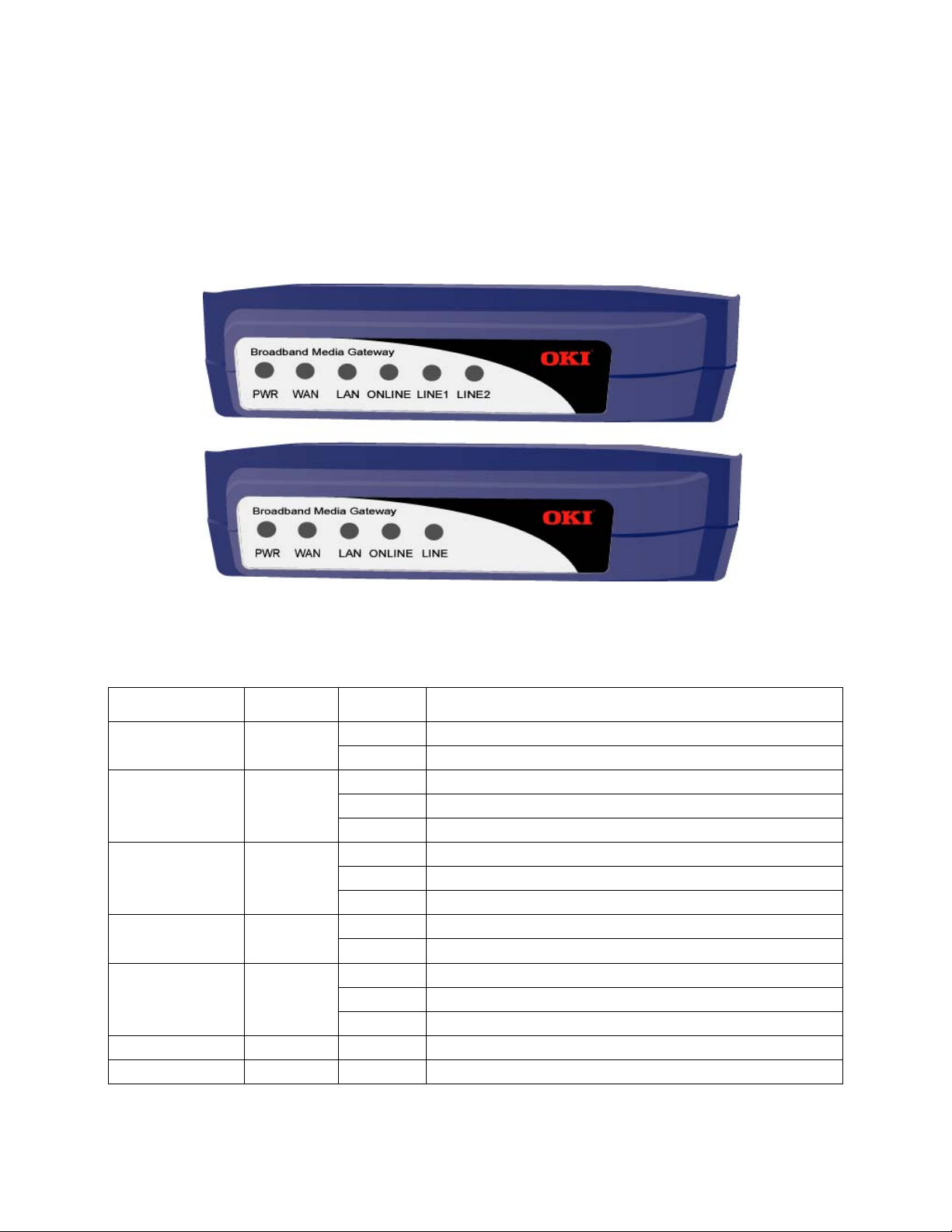
2.1 Front View (LEDs)
Figure 1 - The front panel of the BMG7011 and BMG7012 VoIP gateways
LED Color Status Description
PWR Green
WA N
LAN Green
ONLINE Green
LINE
LINE1 & LINE2
WAN/LAN/ONLINE Green
ONLINE/LINE(s) Green
Green
Green
On When the BMG7011 and BMG7012 VoIP gateways is powered on
Off No power provided
Blinking When data is being transmitted or received
On When WAN Link is established
Off When WAN Link is not established
Blinking When data is being transmitted or received
On When LAN Link is established
Off When LAN Link is not established
On When VoIP telephone service is ready
Off When VoIP telephone service is not ready. Phone line is connected directly to PSTN
Blinking When there is an incoming call (the telephone is ringing)
On When the telephone is in use
Off When telephone is not in use
All Blinking Momentary blinking indicating gateway Reboot
All Blinking Simultaneous blinking indicates Firmware upload in progress
© Copyright, 2004 Oki Network Technologies. All Rights Reserved 3
Page 9
BMG7011 and BMG7012 User’s Guide Rev. 1.9
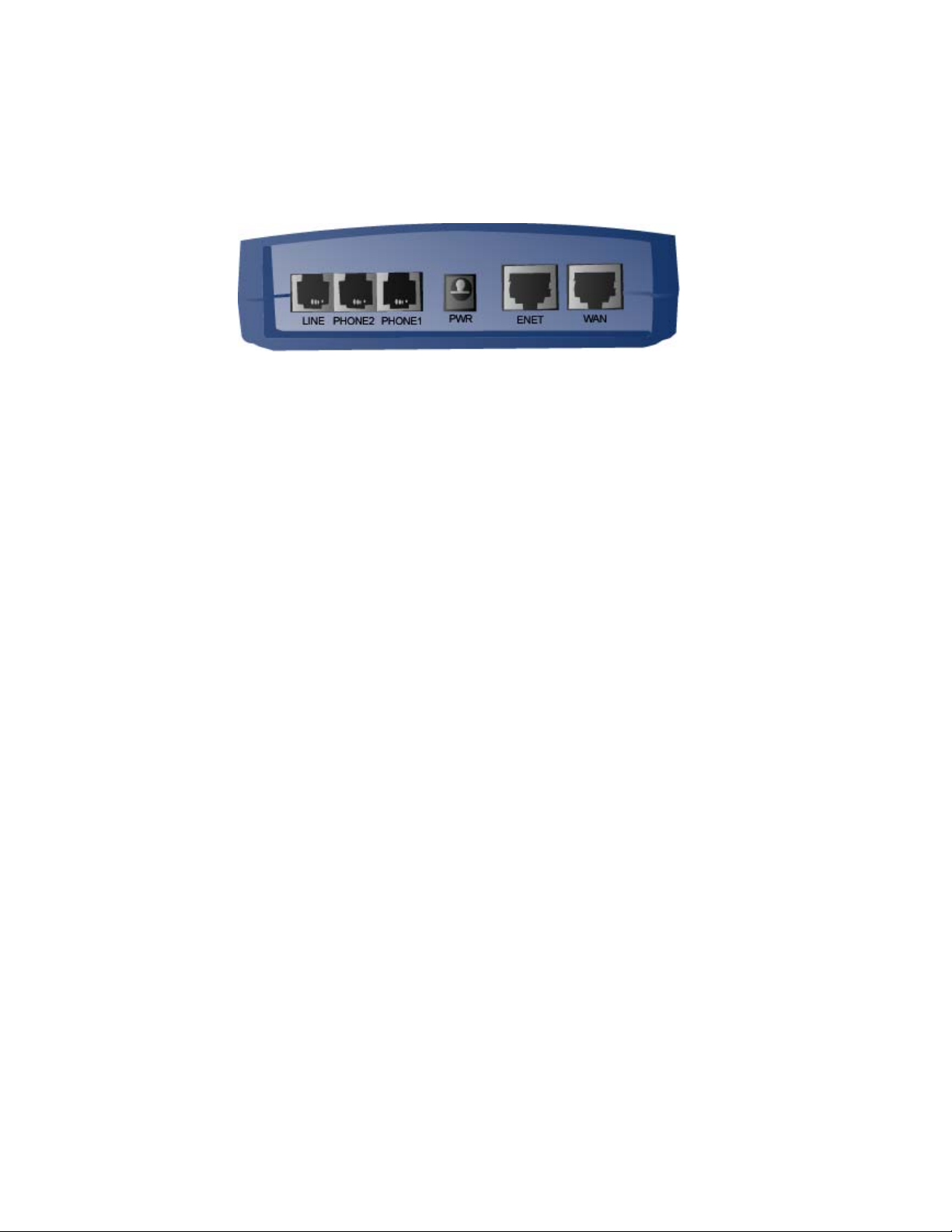
2.2 Rear View (Ports)
Figure 2 - The rear panel of the BMG7011 and BMG7012 VoIP gateways
• LINE: RJ-11 connector, connected to PSTN back-up line
• PHONE1 & PHONE2: RJ-11 connectors, connected to analog telephones or Fax machines
• PWR: Power connector, connected to the power adapter packaged with the BMG unit
• ENET: Ethernet RJ-45 connector, connected to PC using a RJ-45 Ethernet cable (optional)
• WA N : Ethernet RJ-45 connector, connected to WAN access device, such as the
cable modem or ADSL modem
© Copyright, 2004 Oki Network Technologies. All Rights Reserved 4
Page 10
BMG7011 and BMG7012 User’s Guide Rev. 1.9
2.3 Initial Installation Procedures for ADSL and Cable Networks
Prior to installing the BMG7011/7012 into the network, the units must be setup to work within either a PPPoE, DHCP,
or Static IP environment. This is accomplished prior to placement of the unit into the network.
1. Configuring TCP/IP Protocol for your PC allowing for entry into web based setup screens
configuring the BMG7011 and BMG7012 VoIP gateways in Supervisor Mode
2. Setting your BMG to communicate through PPPoE
3. Setting your BMG to communicate through DHCP
4. Setting your BMG to communicate through a Static IP address
Steps involved with
2.3.1 Configuring TCP/IP Protocol for Your PC
To communicate with and configure this device, you will need to set your PC ‘s IP protocol to the default BMG IP
Address. If you enable static IP addressing, make sure your PC resides in the same subnet with this device’s LAN IP
Address (default IP Address: 192.168.100.1, default subnet mask: 255.255.255.0).
For Windows 98/Me
1. From the Start menu, click Settings, and then click Control Panel.
Double-click Network.
2.
On the Configuration tab, check if TCP/IP protocol is installed on the components list.
3.
If yes, go to Step 8. If no, then click
4.
5.
Highlight
Protocol
and click
Add
.
Add
.
6. Select Microsoft from the Manufactures list and select TCP/IP from the Network Protocols list.
Click OK. You will see TCP/IP displayed on the network components list.
7.
Highlight TCP/IP and click Properties.
8.
9.
Select the
IP Address
tab and check
Specify an IP address
.
10. Set IP address as 192.168.100.100, Subnet mask as 255.255.255.0 and press OK.
For Windows 2000/XP
1.
From the
menu, click
Start
Settings,
and then click
Network and Dial-up Connections
.
© Copyright, 2004 Oki Network Technologies. All Rights Reserved 5
Page 11

BMG7011 and BMG7012 User’s Guide Rev. 1.9
Double-click Local Area Connection.
2.
3.
Click
Properties
.
4. Click Internet Protocol (TCP/IP) and then click Properties.
5. Check Use the following IP address.
Set IP address as 192.168.100.100, Subnet mask as 255.255.255.0 and press OK.
6.
For Windows NT
1. From the Start menu, click Settings, and then click Control Panel.
Double-click Network.
2.
On the Protocol tab, check if TCP/IP protocol is installed on the components list.
3.
If yes, go to Step 7. If no, then click
4.
Add
.
5. Highlight TCP/IP Protocol and click OK.
6. When asked to use DHCP, click No.
Select TCP/IP Protocol and click Properties.
7.
When Information Message appears, click OK.
8.
9.
On the
IP Address
tab, check
Specify an IP address.
10. Set IP address as 192.168.100.100, Subnet mask as 255.255.255.0 and press OK.
When asked to restart your computer, click Yes .
11.
For Linux
1. In command line interface, enter netconf.
2. Highlight and click Host name and IP network devices.
Set IP address as 192.168.100.100, Subnet mask as 255.255.255.0.
3.
Highlight and click Accept to save the configuration.
4.
2.4 Configuring the BMG7011 and BMG7012 VoIP gateways
Oki has integrated a powerful Web based server within the BMG7011 and BMG7012 gateways for quick and easy
verification of connection status and device configuration.
2.4.1 Configuring via Web Browser
Once your PC is properly configured, please proceed the following steps:
1. Start the web browser.
2. Enter the default IP address 192.168.100.1 of this device in the Address box to access the web configuration
menu.
© Copyright, 2004 Oki Network Technologies. All Rights Reserved 6
Page 12
BMG7011 and BMG7012 User’s Guide Rev. 1.9
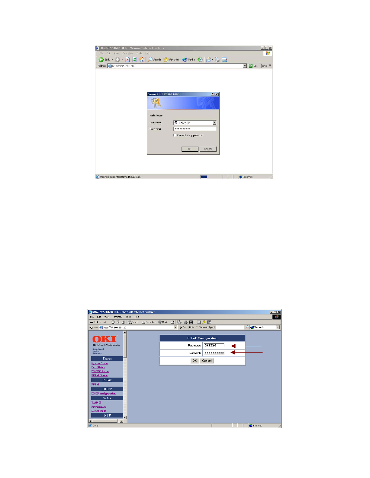
3. The web configuration menu provides two operation modes: Supervisor Mode and User Mode. The web
configuration menu
Supervisor Mode:
When the following window pops up, enter the predefined user name as supervisor and password as
okiconnect and then press OK key.
User Mode:
For User mode login, enter “user” in the User Name entry cell “guest” in the Password entry cell – press OK.
varies according to different operation mode.
2.4.2 Setting your BMG to communicate through PPPoE
© Copyright, 2004 Oki Network Technologies. All Rights Reserved 7
Page 13
BMG7011 and BMG7012 User’s Guide Rev. 1.9
Enter Username and Password (supplied by Service Provider) in the PPPoE Configuration setup screen.
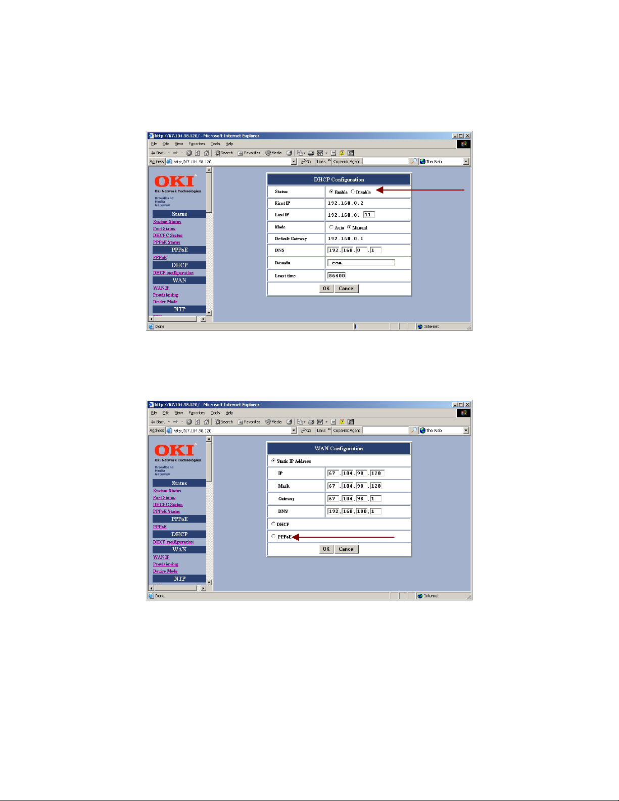
If communicating over PPPoE, you must select <Disable> in the DHCP Configuration setup screen.
Select PPPoE within the WAN Configuration setup screen.
© Copyright, 2004 Oki Network Technologies. All Rights Reserved 8
Page 14
BMG7011 and BMG7012 User’s Guide Rev. 1.9
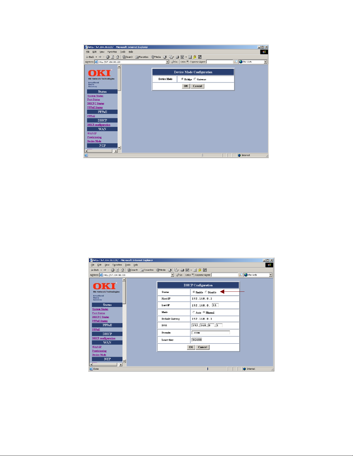
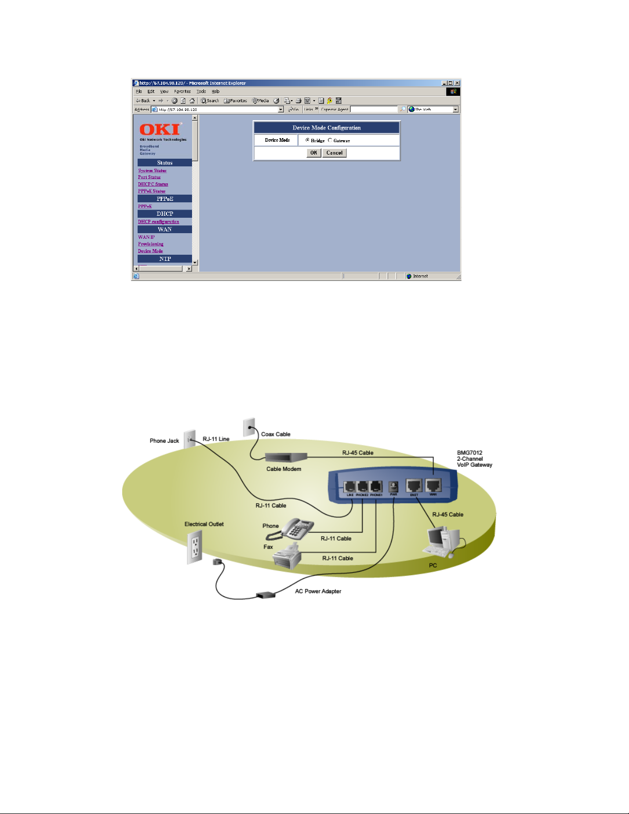
Finally, select either <Bridge> or <Gateway> within the Device Mode Configuration setup screen.
SAVE configuration settings.
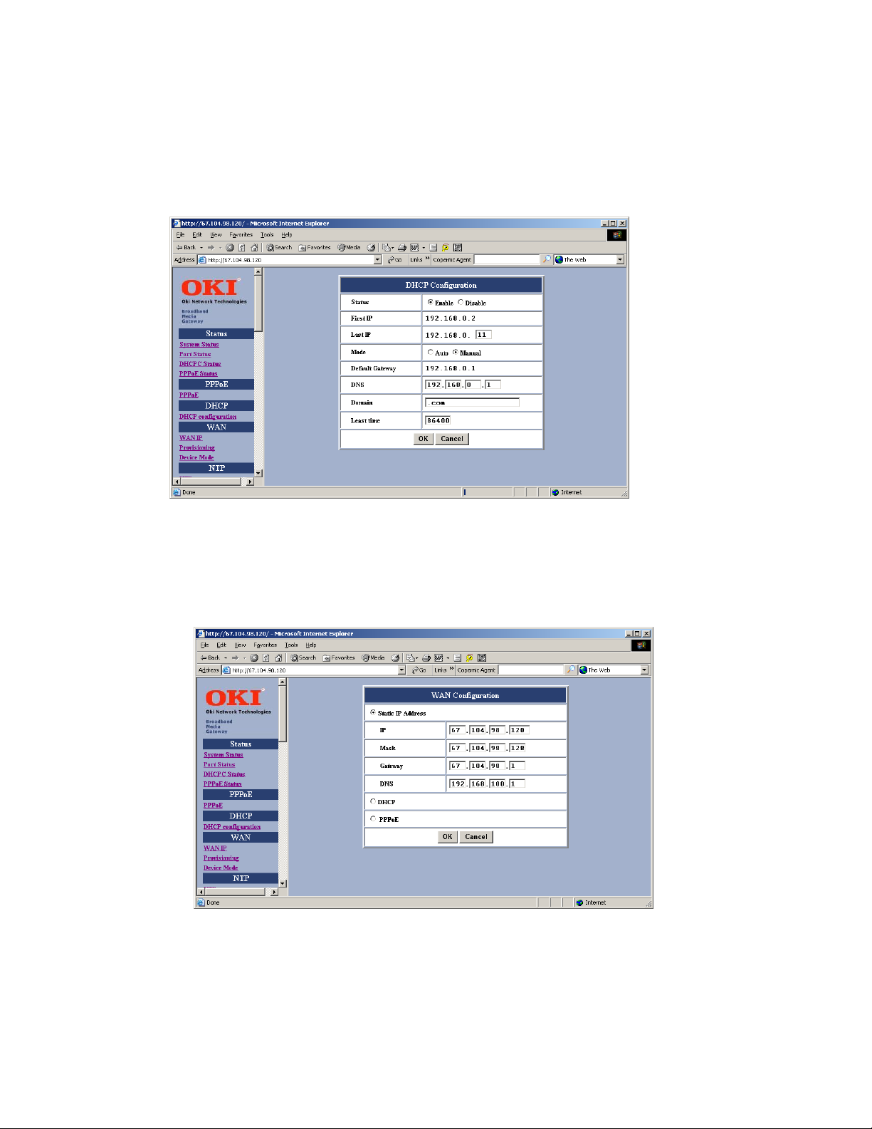
2.4.3 Setting your BMG to communicate through DHCP
If communicating over DHCP, you must select <Enable> in the DHCP Configuration setup screen.
© Copyright, 2004 Oki Network Technologies. All Rights Reserved 9
Page 15
BMG7011 and BMG7012 User’s Guide Rev. 1.9
Select DHCP within the WAN Configuration setup screen.
Finally, select either <Bridge> or <Gateway> within the Device Mode Configuration setup screen.
SAVE configuration settings.
© Copyright, 2004 Oki Network Technologies. All Rights Reserved 10
Page 16
BMG7011 and BMG7012 User’s Guide Rev. 1.9
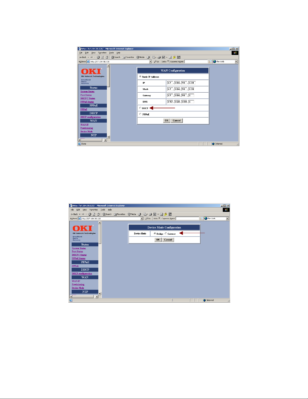
2.4.4 Setting your BMG to communicate through a Static IP address
The BMG7011 and BMG7012 VoIP Gateways can be setup to communicate over a Static IP address.
If communicating with a Static IP address then <disable> DHCP.
Select Static IP Address. Enter IP, Mask, Gateway, and DNS addresses supplied by Service Provider.
© Copyright, 2004 Oki Network Technologies. All Rights Reserved 11
Page 17
BMG7011 and BMG7012 User’s Guide Rev. 1.9
Finally, select either <Bridge> or <Gateway> within the Device Mode Configuration setup screen.
SAVE configuration settings.
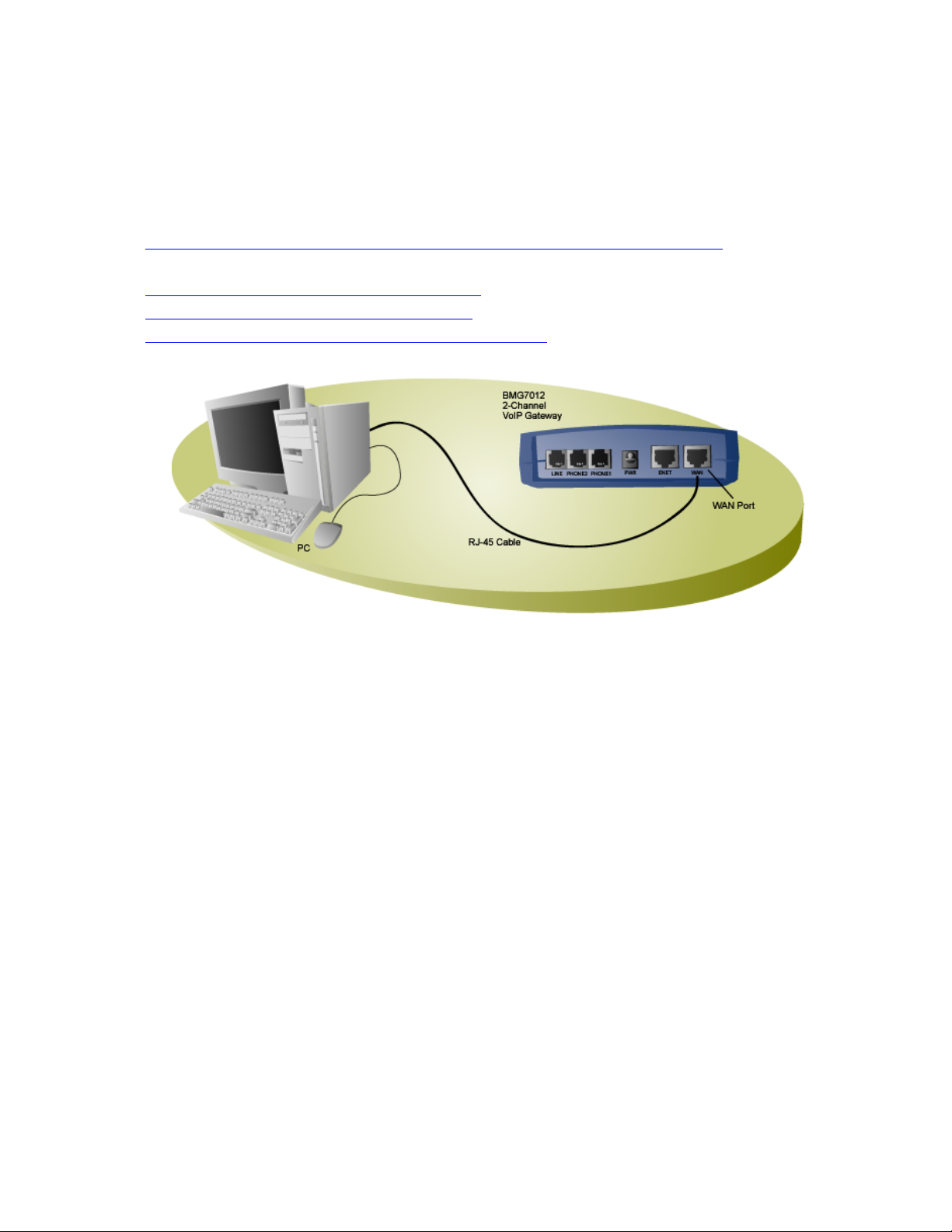
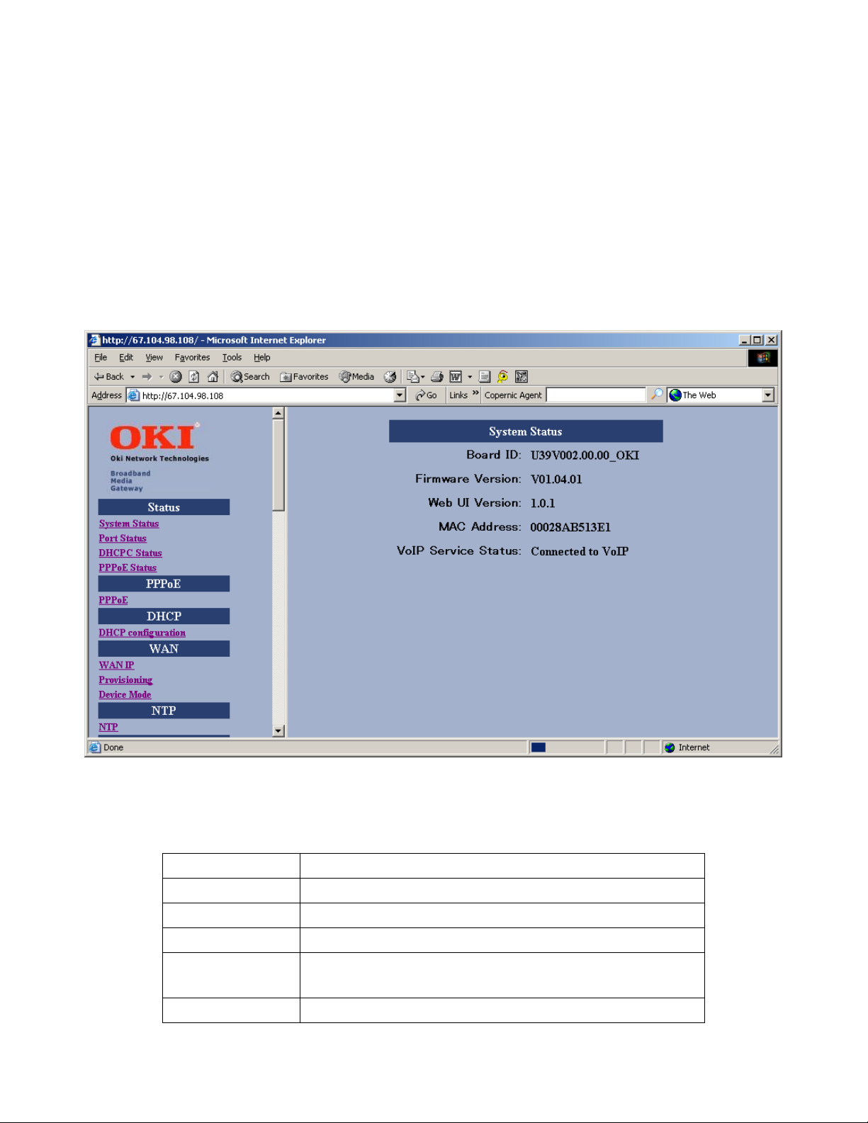
2.5 Installation Overview For ADSL and Cable Networks
Example DSL installation
© Copyright, 2004 Oki Network Technologies. All Rights Reserved 12
Page 18
BMG7011 and BMG7012 User’s Guide Rev. 1.9
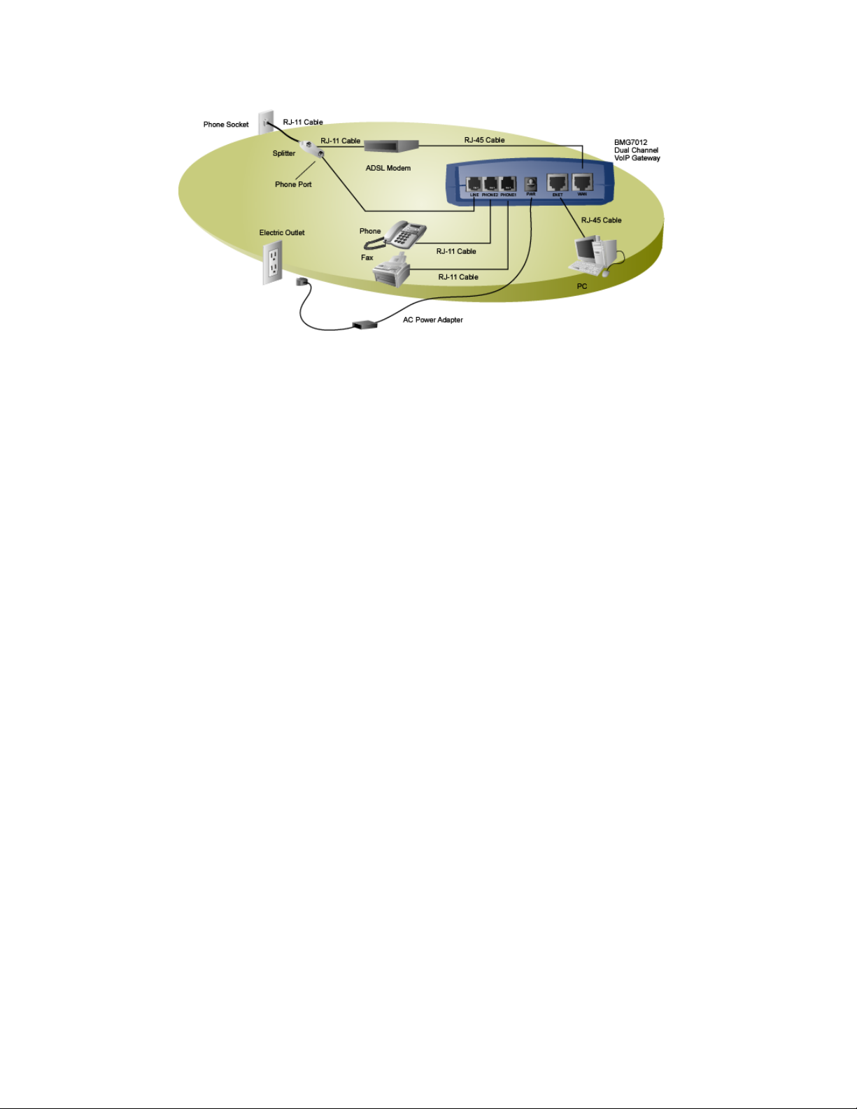
Example Cable installation
Figure 3: Installation Diagrams
1. WA N : Plug one end of the RJ-45 Ethernet cable into the WAN port and plug the other end into the Ethernet port
of the Internet service device, such as the cable modem or ADSL modem. Then connect the cable modem or
ADSL modem to the modem port of the splitter using a RJ-11 telephone line.
2. PHONE1 & PHONE2:
Plug one end of the RJ-11 telephone cable into the PHONE1 or PHONE2 port and plug the other end into the
phone socket on a telephone set.
3. LINE: (optional)
ADSL: Plug one end of the RJ-11 telephone cable into the LINE port and plug the other end into the phone port
of the splitter. Then connect the splitter to the phone socket in the wall using a RJ-11 telephone cable.
Cable: Plug one end of the RJ-11 telephone cable into the LINE port and plug the other end into the phone
socket in the wall.
The LINE port is for back-up use allowing for direct connection to the PSTN (Public Switched Telephone
Network). If the BMG7011 and BMG7012 VoIP gateways lose WAN connection or the VoIP function is not
available, the BMG7011 and BMG7012 will allow the analog telephone to access the PSTN service.
4. ENET: (optional)
Plug one end of the RJ-45 Ethernet cable into the ENET port and plug the other end into the Ethernet socket of
NIC on your PC. (Optional for the PC to connect to the Internet.)
5. PWR:
Plug one end of the power adapter into the PWR port and plug the other end into an electric outlet on the wall.
© Copyright, 2004 Oki Network Technologies. All Rights Reserved 13
Page 19

BMG7011 and BMG7012 User’s Guide Rev. 1.9
3. Web Interface Screen Descriptions
The following pages contain brief descriptions of each web page and its functions within the web based
configuration web server. To apply any setting altered on any page, click OK. To clear values entered on the
screen, click Reset. Changing to another screen without clicking OK will not save the settings you have made.
Remember to click OK before browsing screens or your configuration will be ignored.
Note: After making all necessary settings, you need to save the configurations and then reboot the BMG to
make the new settings take effect.
Resetting to Default (firmware v01.04.01 or higher)
To reset BMG settings to “default” settings, or to reset a password and if your firmware is version 01.04.01 or
higher, you can use the Keypad (Analog phone connect to first port) to Reset-To-Default (dial *#123).
© Copyright, 2004 Oki Network Technologies. All Rights Reserved 14
Page 20
BMG7011 and BMG7012 User’s Guide Rev. 1.9
3.1 Status
3.1.1 System Status:
The setup screen, example below, will be displayed when you first connect. This screen contains Board ID, Firmware
Version, Web UI Version, and MAC Address.
Figure 4 – System Status Window
Item Description
Board ID Board ID is used to identify the unit and upgrade the firmware
Firmware Version
Web UI Version Specifies the current Web User Interface version.
MAC Address
VoIP Service Status Specifies VoIP service status
© Copyright, 2004 Oki Network Technologies. All Rights Reserved 15
Specifies the installed firmware version.
Specifies the unique hardware address of the BMG7011 and BMG7012 VoIP Gateways.
Used for automated provisioning
Page 21
BMG7011 and BMG7012 User’s Guide Rev. 1.9
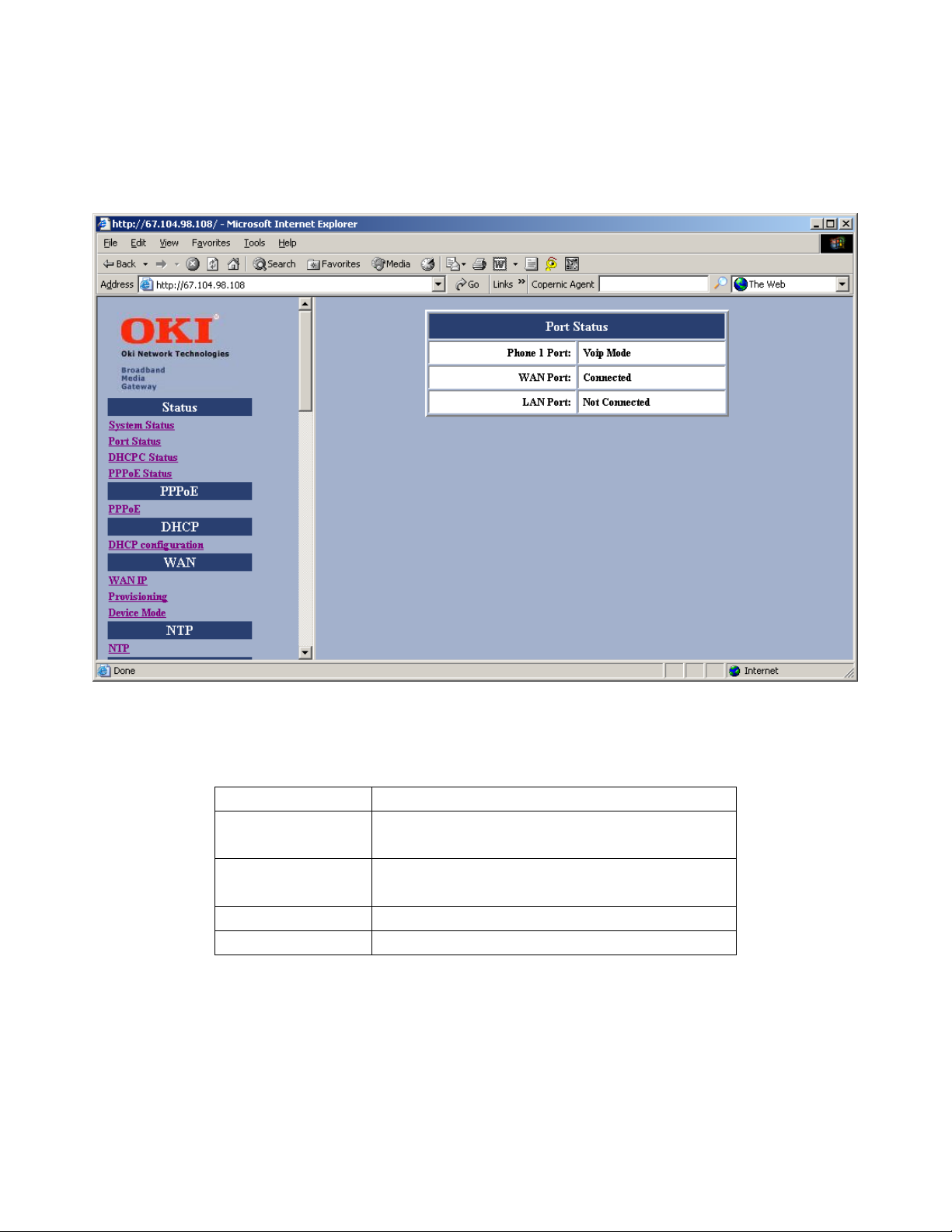
3.1.2 Port Status:
You can check the status of all I/O ports by clicking Port Status.
Figure 5 – Port Status Window
Item Description
Phone 1 Port Shows phone status either VoIP mode or PSTN mode (PSTN mode when
VoIP is not available)
Phone 2 Port Shows phone status either VoIP mode or PSTN mode (PSTN mode when
VoIP is not available)
WAN Port Shows WAN Link status either connected or not connected
LAN Port Shows LAN Link status either connected or not connected
© Copyright, 2004 Oki Network Technologies. All Rights Reserved 16
Page 22

BMG7011 and BMG7012 User’s Guide Rev. 1.9
3.1.3 DHCPC Status:
If you enable DHCP mode, you can see the status by clicking DHCPC Status (“C”-connection).
Figure 6 – DHCPC Status Window
Item Description
IP Assigned IP Address assigned by DHCP server for this unit
Subnet Mask Subnet Mask
Broadcast Broadcast
Gateway Default Gateway
DNS DNS Address
NTP Server IP Address of NTP Server.
Provision Server
IP Address of Provision Server.
© Copyright, 2004 Oki Network Technologies. All Rights Reserved 17
Page 23

BMG7011 and BMG7012 User’s Guide Rev. 1.9
3.1.4 PPPoE Status:
If you enable PPPoE mode for WAN, you can see the status by clicking PPPoE Status.
Figure 7 – PPPoE Status Window
Item Description
Service Name
AC Name Server name assigned by PPPoE for this unit
Local IP IP address
Remote IP Server IP address.
DNS1 DNS IP address (Primary)
DNS2 DNS IP address (Secondary)
WIN1
WIN2 WIN address (Secondary)
Service name assigned by PPPoE for this unit
WIN address (Primary)
© Copyright, 2004 Oki Network Technologies. All Rights Reserved 18
Page 24

BMG7011 and BMG7012 User’s Guide Rev. 1.9
3.1.5 PPPoE Configuration:
If you select PPPoE to get WAN IP Address of the BMG7011 and BMG7012 VoIP gateways, you need to enter the
User name and Password provided by your ISP.
Figure 8 – PPPoE Configuration Window
Item Description
Username Provide username obtained from your ISP
Password Provide password obtained from your ISP
© Copyright, 2004 Oki Network Technologies. All Rights Reserved 19
Page 25

BMG7011 and BMG7012 User’s Guide Rev. 1.9
3.2 DHCP Server Configuration
3.2.1 DHCP Configuration
If the device mode is gateway mode, we support DHCP Server on LAN side to assign IP address, etc. to the PC(s)
connected to the LAN port. You can set the Status, Last IP and Mode etc. on this page. After you make the settings,
click OK for the settings to immediately take effect.
Figure 9 – DHCP Configuration Window
Item Description
Status The DHCP Server is enabled or disabled.
Last IP The last IP can be assigned by the DHCP server.
Mode The network settings assigned to the DHCP Client is Auto mode or Manual Mode. In Auto mode, the DNS
settings are from the WAN side. In Manual mode, the DNS settings are from the user’s input in this page.
DNS You can manually set the value in Manual mode or it takes the value from WAN side in Auto mode.
Domain You can manually set the value in Manual mode or it takes the value from WAN side in Auto mode.
Least time The least time of the DHCP client to holding the network settings. The value is useful in Auto mode.
© Copyright, 2004 Oki Network Technologies. All Rights Reserved 20
Page 26

BMG7011 and BMG7012 User’s Guide Rev. 1.9
3.3 WAN Configuration
3.3.1 WAN IP
You can select the method to obtain the IP address of the VoIP Gateway by selecting one of the following modes.
After the BMG is rebooted, the settings you have made will take effect.
Figure 10 – WAN Configuration Window
Item Description
Static IP Address The IP address of the WAN side is assigned by the user.
IP The IP address of the WAN side for static IP assignment
Mask
Gateway The IP address of the default Gateway of WAN side for static IP assignment
DNS
DHCP The IP Address of the WAN side is assigned by the ISP’s DHCP server
PPPoE
© Copyright, 2004 Oki Network Technologies. All Rights Reserved 21
The subnet mask of the WAN side for static IP assignment
The IP Address of Domain Name Server of WAN side for static IP assignment
The IP Address of the WAN side is assigned by ISP’s PPPoE server
Page 27

BMG7011 and BMG7012 User’s Guide Rev. 1.9
3.3.2 Remote Provisioning
If the Provisioning is off, telnet and http access from WAN port is blocked. This function is only active in gateway
mode.
Figure 11 – Provisioning Configuration Window
Item Description
Status Turn Off or On remote provisioning
Caution: Be careful, once remote provisioning is turned “Off”, there is no way to
login to the unit remotely. The only option to login to the unit is from the LAN port
using default IP address 192.168.0.1
© Copyright, 2004 Oki Network Technologies. All Rights Reserved 22
Page 28

BMG7011 and BMG7012 User’s Guide Rev. 1.9
3.3.3 Device Mode
If the Device Mode is set to Gateway, NAPT is enabled. On the contrary, if Device Mode is set to Bridge, NAPT is
disabled.
Figure 12 – Device Mode Configuration Window
Item Description
Device Mode Select Bridge mode or Gateway mode
© Copyright, 2004 Oki Network Technologies. All Rights Reserved 23
Page 29

BMG7011 and BMG7012 User’s Guide Rev. 1.9
3.4 NTP
3.4.1 NTP
Network Time Protocol used for setting gateway configurations to obtain time information from a public network
timeserver. (example: 198.123.30.132)
Figure 13 – Device Mode Configuration Window
Item Description
NTP Server Set IP Address
Expires Time designated for re-query. Expiration set in seconds
Time Zone Geographical time zone based on GMT
© Copyright, 2004 Oki Network Technologies. All Rights Reserved 24
Page 30

BMG7011 and BMG7012 User’s Guide Rev. 1.9
3.5 NAPT Configuration
3.5.1 Port Forwarding
You can add or delete
Port Forwarding Rule
to the device in
Gateway mode
. When the packet travels through the
gateway, if the port of the packet matches the port of port-forwarding rule, then packet will be forwarded to the
private IP address configured of the matched rule.
Figure 14 – Port Forwarding Rule/Rule Table Window
Item Description
Tcp/udp/both Select if you want to forward the packet based on tcp, udp or both
Forward Port The tcp or udp port number for which you want to forward
To Private IP The IP Address of the pc in the LAN side is forwarding to
ID The ID of the port forwarding rule is to be deleted
Rule Table Maximum of 10 forwarding together with IP Filtering can be specified
© Copyright, 2004 Oki Network Technologies. All Rights Reserved 25
Page 31

BMG7011 and BMG7012 User’s Guide Rev. 1.9
3.5.2 IP Filtering
You can add or delete IP Filter Rule to the device in Gateway mode. When the packet enters the VoIP Gateway, the
packet will be blocked if the source IP of the packet matches the rule of IP Filter.
Figure 15 – IP Filter Configuration Window
Item Description
Public IP The Public IP Address is to be filtered.
ID The ID of the IP Filter rule is to be deleted.
IP Filter Table Maximum of 10 entries together with Port Forwarding can be
specified.
© Copyright, 2004 Oki Network Technologies. All Rights Reserved 26
Page 32

BMG7011 and BMG7012 User’s Guide Rev. 1.9
3.5.3 DMZ
You c an enable or disable DMZ and specify the IP address of DMZ in Gateway mode. When an unfiltered packet
enters the VoIP Gateway it will be transferred to the DMZ, not port-forwarded, and not matched for the NAPT
binding.
Figure 16 – DMZ Configuration Window
Item Description
DMZ The DMZ is disabled or enabled.
DMZ IP address
© Copyright, 2004 Oki Network Technologies. All Rights Reserved 27
The IP address of the DMZ.
Page 33

BMG7011 and BMG7012 User’s Guide Rev. 1.9
3.6 QoS
3.6.1 QoS Configuration
You can decide the
QoS type
of the packets sent out of the BMG VoIP gateway. If the type of
is DiffServ, you
QoS
can also specify the different values for Signal DSCP and Media DSCP. Both ToS and DSCP QoS are supported for
VoIP packets sent out from the BMG VoIP Gateway.
Figure 17 – QoS Configuration Window
Item Description
QoS Type The type of QoS can be disabled, DiffServ, or ToS.
ToS The value of ToS is usually between 8~120.
Signal DSCP The value of Differentiated Services Code Point for Signal. (4~255)
Media DSCP The value of Differentiated Services Code Point for Media. (4~255)
© Copyright, 2004 Oki Network Technologies. All Rights Reserved 28
Page 34

BMG7011 and BMG7012 User’s Guide Rev. 1.9
3.6.2 DSCP Configuration
You can set the DSCP mode to Trusted or Un-Trusted. The DSCP mode of operations is supported for PC data
traffic through the LAN interface. If it is set to Trusted Mode, the BMG will preserve the DSCP settings from the
LAN interface. If it is set to Un-Trusted mode, the BMG will remark to DSCP DE before forwarding to Uplink
interface.
Figure 18 – DHCP Configuration Window
Item Description
DSCP Mode Select Trusted mode or Un-trusted mode
© Copyright, 2004 Oki Network Technologies. All Rights Reserved 29
Page 35

BMG7011 and BMG7012 User’s Guide Rev. 1.9
3.6.3 VLan Configuration
You can enable the VLan tag with VLan ID and priority for Data and Voice.
Figure 19 – DHCP Configuration Window
Item Description
VLan Tag
Data Priority Set Data priority between 0-7
Data VLan ID
Voice Priority Set Voice priority between 0-7
Voice VLan ID
Enable VLAN mode or disable VLAN mode
Set Data VLAN ID between 2~4094
Set Voice VLAN ID between 2~4094
© Copyright, 2004 Oki Network Technologies. All Rights Reserved 30
Page 36

BMG7011 and BMG7012 User’s Guide Rev. 1.9
3.7 Mac Cloning
This function is intended mainly for users connecting through a cable modem connection. Some ISPs require the
MAC address registration of the computer behind the cable modem before connections can be established. The BMG
takes the place of the computer behind the modem, and the local user can use the MAC Cloning option to enter the
original PC MAC address without the need to contact the ISP.
Figure 20 –Mac Cloning Window
Item Description
Mac Cloning Enables MAC Cloning mode or disables MAC Cloning mode
Mac Address
© Copyright, 2004 Oki Network Technologies. All Rights Reserved 31
Specify the MAC address for MAC spoofing.
Page 37

BMG7011 and BMG7012 User’s Guide Rev. 1.9
3.8 PSTN Configuration
3.8.1 Switch Key
This functions allows user to set PSTN switch number. User can switch VoIP mode to PSTN mode by entering a
4-digit entry. “0000” is the default value. In the event IP service from provider is down, or to make calls via the PSTN
network, users can enter four-digit code and instantly make calls over PSTN.
Figure 21 –PSTN Switch Key Window
Item Description
PSTNWKEY Specify digit for immediate PSTN Access
© Copyright, 2004 Oki Network Technologies. All Rights Reserved 32
Page 38

BMG7011 and BMG7012 User’s Guide Rev. 1.9
3.8.2 Digit Map
This function allows user to set the Digit Map. User can set up a list of numbers with specific prefix and total length
of phone number to switch from VoIP mode to PSTN mode. When user enters in specific, predefined phone numbers,
the BMG gateway will automatically send these calls over the PSTN.
Figure 22 –PSTN Digitmap Window
Item Description
Prefix Enter the prefix of the telephone number. The maximum length is 15 digits.
Length
Add/Modify Add or modify your desired prefix and length of the telephone number with 15 maximum entries
Delete Delete an existing prefix and length of the telephone number from the Digit Map Table
Refresh Press this button will show new changes
© Copyright, 2004 Oki Network Technologies. All Rights Reserved 33
Enter the total length of the telephone number. The length is ranged from 0~64. “0” means the
length is not fixed.
Page 39

BMG7011 and BMG7012 User’s Guide Rev. 1.9
3.9 Provision Configuration
The BMG7011/ 7012 gateways support a Provisioning Configuration mechanism to set the gateway configuration
parameters. When the Gateway downloads the configuration file from the Provisioning server, it will compare the
downloaded parameters and existing local parameters. If the former is newer, the existing local setting parameters
will be overwritten and the downloaded setting parameters will be written into the FLASH memory. This feature sets
Provision Configurations including server address, server port number, group, and expiry time. Save and Reboot.
Figure 23 –Provision Configuration Window
Item Description
Server Address The IP Address of Provision Server. Enter the address provided by your ISP.
Server Port The receiving port number of Provision Server. Enter the value provided by your ISP.
Group
Expires Periodic time in seconds to check new update for configuration to provisioning server. Enter the
© Copyright, 2004 Oki Network Technologies. All Rights Reserved 34
Enter the string for different user group. The maximum length is 64. Enter the value provided by
your ISP.
value provided by your ISP.
Page 40

BMG7011 and BMG7012 User’s Guide Rev. 1.9
3.10 Syslog Configuration
The BMG7011/ 7012 VoIP gateway supports Syslog. Syslog is used to send UDP packets via Syslog port (514) and
keep messages in the Log Server.
Figure 24 –Syslog Configuration Window
Item Description
Server Address Specify the IP Address of Syslog server.
Server Port Specify the port number of Syslog server.
© Copyright, 2004 Oki Network Technologies. All Rights Reserved 35
Page 41

BMG7011 and BMG7012 User’s Guide Rev. 1.9
3.11 EMS Configuration
3.11.1 EMS
This VoIP gateway supports EMS management function. Users can set the EMS configuration including Server
Address, Server Port, Community, and expiration time.
Figure 25 –EMS Configuration Window
Item Description
Server Address Specifies the IP address of EMS server
Server Port Specifies the Port number of EMS Server
Community
Expires Specifies the valid period of the VoIP gateway managed by EMS Server. The unit is second.
© Copyright, 2004 Oki Network Technologies. All Rights Reserved 36
Specifies the Community used to EMS Server
Page 42

BMG7011 and BMG7012 User’s Guide Rev. 1.9
3.11.2 SNMP Community
The BMG7011/ 7012 VoIP Gateway supports SNMP agent. Users can use EMS to manage the VoIP Gateway via
SNMP protocol. Save and Reboot.
Figure 26 –SNMP Community Configuration Window
Item Description
Set Community The Community is used when the user sets OIDs (Object Identifiers)
Get Community The Community is used when the user gets OIDs (Object Identifiers)
Trap Community The Community is used when the user processes the traps.
© Copyright, 2004 Oki Network Technologies. All Rights Reserved 37
Page 43

BMG7011 and BMG7012 User’s Guide Rev. 1.9
3.11.3 SNMP Trap Target
The BMG7011/ 7012 VoIP gateways support (4) Trap targets. You can specify each IP and Port to receive the traps
sent from the VoIP Gateway. Save and Reboot.
Figure 27 –SNMP Trap Configuration Window
Item Description
Tra p The traps will be sent (on) or not (off).
IP Specify the IP Address to which the traps of the VoIP Gateway will be sent.
Port Specify the Port to which the traps of the VoIP Gateway will be sent.
© Copyright, 2004 Oki Network Technologies. All Rights Reserved 38
Page 44

BMG7011 and BMG7012 User’s Guide Rev. 1.9
3.12 VoIP Configuration
3.12.1 Protocol
This screen allows you to set the preferred protocol.
Figure 28 – VoIP User Configuration Window
Item Description
MGCP Select MGCP for MGCP Protocol
SIP Select SIP for SIP Protocol
H.323 Select H.323 for H.323 Protocol
© Copyright, 2004 Oki Network Technologies. All Rights Reserved 39
Page 45

BMG7011 and BMG7012 User’s Guide Rev. 1.9
3.12.2 User
This screen allows you to set the user information such as username, password and display name. You should obtain the
values from your service provider for these services. Save and Reboot.
Figure 29 – VoIP User Configuration Window
Item Description
User (check box)
Username
Password
Display name
© Copyright, 2004 Oki Network Technologies. All Rights Reserved
Check user0 or user1 or both for phone to be used
Specifies the name (or phone number) of the user
Specifies the password of the user
Specifies the displayed user name for H.323 protocol specifies
H.323 ID
40
Page 46

BMG7011 and BMG7012 User’s Guide Rev. 1.9
3.12.3 MGCP
This screen allows you to make MGCP configurations including local port, call agent address, call agent port number,
wild-carded RSIP, Name style, and expiry time.
Figure 30 – VoIP MGCP Configuration Window
Item Description
Local Port
Call Agent Address
Call Agent Port
Wild-carded
RSTP
Endpoint name style
Expires
© Copyright, 2004 Oki Network Technologies. All Rights Reserved
This port number is identified to receive/send data from/to the Call Agent.
Specifies the IP Address of Call Agent.
This port number is identified to receive/send data from/to the VoIP Gateway.
Enabling this field permits the use of wild card signals to replace RTP with RSTP.
Sets Endpoint name style.ex. aaln/#@[ip_addr] / mac_addr/#@[ip_addr] / aaln/#@mac_addr
“Expires” specifies the period (in seconds) that the VoIP Gateway sends keeping-alive message
to the Call Agent.
This is to help check the connection status in case the VoIP Gateway is accidentally
41
Page 47

BMG7011 and BMG7012 User’s Guide Rev. 1.9
disconnected from the Call Agent.
3.12.4 SIP
This screen allows you to make SIP configurations including local port, SIP proxy server address, port number, registrar
server address, port number, expiry time, SIP domain, and subject. Save and Reboot.
Figure 31 – VoIP SIP Configuration Window
Item Description
Local Port
Proxy Address
Proxy Port
Registrar Address
Registrar Port
Expires
© Copyright, 2004 Oki Network Technologies. All Rights Reserved
Specifies the port number of the SIP stack. 5060 is the default port number.
Specifies the IP address of SIP proxy server
Specifies the port number of SIP proxy server
Specifies the IP address of Registrar server. Registrar server is often the same as SIP proxy server
Specifies the port number of Registrar server.
“Expires” specifies the period (in seconds) that the VoIP Gateway sends Registration message to
Registrar server. This is to help check the connection status in case the VoIP Gateway is
42
Page 48

BMG7011 and BMG7012 User’s Guide Rev. 1.9
accidentally disconnected from the Registrar server.
SIP Domain
Subject
Specifies the domain name to which BMG is assigned to by the service provider
Specifies the content of the subject header in outgoing INVITE message. This is used to indicate
the title of the call.
© Copyright, 2004 Oki Network Technologies. All Rights Reserved
43
Page 49

BMG7011 and BMG7012 User’s Guide Rev. 1.9
3.12.5 H.323
This screen allows you to make changes to the H.323 configurations including local port, H.323 Gatekeeper ID,
Gatekeeper Address, port number, H235 Password (optional), expiry time, Fast Start mode, and DTMF signal type. Save
and Reboot.
Figure 32 – VoIP H.323 Configuration Window
Item Description
Local Port
Gatekeeper ID
GK1 Address
GK2 Address
Gatekeeper port
H235 Password
Expires
© Copyright, 2004 Oki Network Technologies. All Rights Reserved
Specifies the port number of the H.323 stack. 1720 is the default port number.
Specifies the ID of Gatekeeper
Specifies the IP address of Gatekeeper.
If Secondary Gatekeeper is specified.
Specifies the port number of Gatekeeper.
Specifies the password for secured registration
“Expires” specifies the period (in seconds) that the VoIP Gateway sends Registration message to
Gatekeeper. This is to help check the connection status in case the VoIP Gateway is accidentally
disconnected from Gatekeeper.
44
Page 50

BMG7011 and BMG7012 User’s Guide Rev. 1.9
Fast Start
DTMF
Enables the Fast start mode or Disable to Normal start mode
Specifies the DTMF signal types
© Copyright, 2004 Oki Network Technologies. All Rights Reserved
45
Page 51

BMG7011 and BMG7012 User’s Guide Rev. 1.9
3.12.6 CODEC
This screen allows you to set CODEC configurations including Codec Rate, Preferred Codec, and VAD. Save and
Reboot.
Figure 33 – VoIP Codec Configuration Window
Item Description
CODEC Rate
Preferred CODEC
VAD
© Copyright, 2004 Oki Network Technologies. All Rights Reserved
“CODEC rate” specifies the packetization time (in milliseconds).
The value is from 10 to 40 ms for G.711 in 10 ms increments (20ms recommended)
The value is from 10 to 80 ms for G.729A in 10 ms increments (20ms recommended)
The value is 30, 60 or 90 ms for G.723.1 (30ms recommended)
Specifies the preferred method of voice compression.
Voice Activity Detection feature.
Enabled: sending packets only while the user is speaking. This will save the bandwidth but cause
the time delay.
46
Page 52

BMG7011 and BMG7012 User’s Guide Rev. 1.9
Disabled: sending packets no matter the user is speaking or not. This will improve the voice
quality to be more smoothly but increase more traffic load.
© Copyright, 2004 Oki Network Technologies. All Rights Reserved
47
Page 53

BMG7011 and BMG7012 User’s Guide Rev. 1.9
3.12.7
Caller ID
This screen allows the user to set the FSK and DTMF. Save and Reboot.
Figure 34 – VoIP Caller ID Configuration Window
Item Description
FSK/ DTMF
Specifies the
Caller ID transmission type.
© Copyright, 2004 Oki Network Technologies. All Rights Reserved
48
Page 54

BMG7011 and BMG7012 User’s Guide Rev. 1.9
3.12.8 RTP
This screen allows user to set RTP port number. Save and Reboot.
Figure 35 – VoIP RTP Configuration Window
Item Description
RTP port
Specifies the RTP port number to the far end device that the voice packet should be received on
this port number
© Copyright, 2004 Oki Network Technologies. All Rights Reserved
49
Page 55

BMG7011 and BMG7012 User’s Guide Rev. 1.9
3.12.9 Tone
This screen allows user to set the tone configu
rations including Rx gain, Tx gain, ringing tone, dial tone, busy tone, ring
back tone, and call waiting tone. You can choose the country tone or you can customize with the following parameters.
Save and Reboot.
Figure 36 – VoIP Tone Configuration Window
Item Description
Country Tone
Rx Gain
Tx Gain
Ring
Dial Tone
Busy Tone
Ring Back Tone
© Copyright, 2004 Oki Network Technologies. All Rights Reserved
Select one of listed countries for country default tone
Adjusts the receiving audio gain to be higher or lower range –15 to 15dB
Adjust the transmitting audio gain to be higher or lower range –15 to 15dB
Sets the ringing cadence (in milliseconds). <ontime, offtime>
Sets the dial tone pattern <ontime, offtime (in milliseconds), freq1, freq2 (in Hz)>
Sets the busy tone pattern <ontime, offtime (in milliseconds), freq1, freq2 (in Hz)>
Sets the ring back tone pattern <ontime, offtime (in milliseconds), freq1, freq2 (in Hz)>
50
Page 56

BMG7011 and BMG7012 User’s Guide Rev. 1.9
Call Waiting
To ne
Sets the call waiting tone pattern <ontime, offtime (in milliseconds), freq1, freq2 (in Hz)>
© Copyright, 2004 Oki Network Technologies. All Rights Reserved
51
Page 57

BMG7011 and BMG7012 User’s Guide Rev. 1.9
3.12.10 FAX
This screen allows user to set the port number for sending/receiving T.38 packets. T.38 protocol supports data-resending
mechanism in case of any missing data during transmission. Save and Reboot.
Figure 37 – VoIP Fax Configuration Window
Item Description
T.38 Fax
T.38 port
© Copyright, 2004 Oki Network Technologies. All Rights Reserved
Enable or disable T.38 Fax transmission
Specifies the T.38 port number for sending/receiving T.38 packets
52
Page 58

BMG7011 and BMG7012 User’s Guide Rev. 1.9
3.12.11 STUN
This screen allows user to set NAT address, STUN server address, STUN server port, local port, and expiry time. Save
and Reboot.
Figure 38 – VoIP STUN Configuration Window
Item Description
NAT Address
STUN Server Address
STUN Server Port
Local Port
Expires
Statically specifies the IP address of the BMG for VoIP if it is installed behind a NAT. The IP address is
the WAN side IP address from the NAT device. Do not set an IP address when STUN is used. STUN will
automatically update this address.
Specifies the IP address of STUN server (Simple Traversal of User Datagram)
Specifies the port number of STUN server
Specifies the local port number of STUN client
“Expires” specifies the period (in seconds) that the VoIP Gateway sends STUN message to STUN server.
This is to help check the connection status in case the VoIP Gateway is accidentally disconnected from
STUN server.
User can dynamically set the IP address for VoIP using STUN. Please set the NAT address to 0
if STUN method is used. Vice versa, if NAT address is used, set the STUN Server Address to 0.
© Copyright, 2004 Oki Network Technologies. All Rights Reserved 53
Page 59

BMG7011 and BMG7012 User’s Guide Rev. 1.9
3.12.12 Speed Dial
The speed dial is used to set up a list of telephone numbers and SIP addresses of the call parties you wish to call.
Figure 39 – VoIP Speed Dial Configuration Window
Item Description
Number
Destination
Add/Modify
Delete
Refresh
© Copyright, 2004 Oki Network Technologies. All Rights Reserved 54
Specifies the abbreviated number of the call party.
Enter the SIP address (or PSTN number) of the call party
(Example: leon.tung@172.11.123.20)
Add or modify the abbreviated number and SIP address or full telephone number of the call
party.
Delete or modify the abbreviated number and SIP address or full telephone number of the call
party from the Speed Dial Table.
Pressing this button will show new changes.
Page 60

BMG7011 and BMG7012 User’s Guide Rev. 1.9
3.12.13 Call Features
Set Call features for BMG including call Hold, call Waiting, call Forwarding. Save and Reboot.
Figure 40 – VoIP Call Feature Configuration Window
Item Description
Port
Call Hold
Call Waiting
Call Transfer
Call Forwarding
Configure port 1 or port 2 – For BMG7012 Only
Enable or Disable Call Hold feature. User can use flash key to hold the other party. Once call hold is disabled, call waiting is also
disabled.
Enable or Disable Call Waiting feature. If a user is talking with one party and the other call come in, a user can use flash key to switch to
either party. If a user wants to disconnect with one party and talk with the other one, a user needs to enter disconnect code
Enable or Disable Call Transfer feature, User can configure the feature code to perform call transfer function without consultation.
Enable or Disable Call Forwarding. There are 3 types Call Forwarding.
Unconditionally forward a call to the destination that user configured.
Always:
Forward a call to the destination that user configured only when the line is busy
Busy:
No-Answer:
Forward a call to the destination that user configured when nobody answers call after # of rings
© Copyright, 2004 Oki Network Technologies. All Rights Reserved 55
Page 61

BMG7011 and BMG7012 User’s Guide Rev. 1.9
3.12.14 Phone book
You can edit the phone book to map the IP and phone number.
Figure 41 – VoIP Call Feature Configuration Window
Item Description
IP Address
Phone Number
Phone Book
© Copyright, 2004 Oki Network Technologies. All Rights Reserved 56
IP Address for the phone # specified
Phone book number to call
Maximum 100 entries
Page 62

BMG7011 and BMG7012 User’s Guide Rev. 1.9
3.13 Password Configuration
3.13.1 Supervisor Password
The password will be used for authentication. It is recommended that you reset the password for administrator
security.
Figure 42 –Supervisor Password Window
Item Description
Old Password Enter the predefined password.
New Password Enter the new password.
Confirm Password Re-enter the new password in this field to ensure it is correct..
© Copyright, 2004 Oki Network Technologies. All Rights Reserved
57
Page 63

BMG7011 and BMG7012 User’s Guide Rev. 1.9
3.13.2 User Password
The password will be used for authentication. It is recommended that you reset the password for user security.
Figure 43 – User Password Window
Item Description
Old Password Enter the predefined password.
New Password Enter the new password.
Confirm Password Re-enter the new password in this field to ensure it is correct..
© Copyright, 2004 Oki Network Technologies. All Rights Reserved
58
Page 64

BMG7011 and BMG7012 User’s Guide Rev. 1.9
3.14 Upgrade Configuration
3.14.1 Firmware
This feature allows you to upgrade the firmware on the VoIP Gateway from the web browser. The firmware on the
VoIP Gateway is stored on FLASH ROM. To upgrade firmware, you need to download the firmware to your local
computer then, click Browse to locate the new firmware on your computer. Click Upgrade to complete the process.
See Firmware upgrade guide for additional information.
Figure 44 – Firmware Upgrade Window
Item Description
Current Version Shows current Firmware version
New Firmware Enter new Firmware’s file name
© Copyright, 2004 Oki Network Technologies. All Rights Reserved
59
Page 65

BMG7011 and BMG7012 User’s Guide Rev. 1.9
3.14.2 Configuration
You can upload to the current configuration to the TFTP server or download a new configuration to the unit from the
TFTP server. You have to specify TFTP IP Address for this purpose. Either the configuration file or phonebook file
can be uploaded or downloaded.
Figure 45 – Configuration Upgrade Window
Item Description
TFTP Configuration Select download/ upload configuration or phonebook
TFTP IP Address Specifies TFTP Server IP Address
TFTP File Name Enter proper file name at TFTP Server for configuration/ phonebook
© Copyright, 2004 Oki Network Technologies. All Rights Reserved
60
Page 66

BMG7011 and BMG7012 User’s Guide Rev. 1.9
3.15 Save
3.15.1 Save Configuration
Whenever you change into a new configuration, you need to save the new configuration data and then restart the
gateway unit to have the new settings take effect. Once you click on the “Save” button from the window below, the
new configuration data is automatically written into the FLASH memory and the system will be refreshed with new
data on your next reboot (refer to the following section “Reboot”).
Figure 46 – Save Configuration to Flash Window
© Copyright, 2004 Oki Network Technologies. All Rights Reserved
61
Page 67

BMG7011 and BMG7012 User’s Guide Rev. 1.8
3.15.2 Load Default Settings
Click on the “Load” button if you would like to restore all default settings of the BMG7011/ 7012. Reboot the
gateway for the new settings to take effect. See the next section “Reboot” for more information.
Figure 47 – Load Default Settings Window
Item Description
Default
Default except current
Network Settings
All value will reset to default
All value will reset to default while the network setting (WAN IP) still remain.
© Copyright, 2003 Oki Network Technologies. All Rights Reserved 62
Page 68

BMG7011 and BMG7012 User’s Guide Rev. 1.8
3.15.3 Reboot
Once you click Reboot, the system will restart and be updated with new configuration data stored in the flash
memory.
Figure 48 – Reboot Window
© Copyright, 2003 Oki Network Technologies. All Rights Reserved 63
Page 69

BMG7011 and BMG7012 User’s Guide Rev. 1.8
Appendix A: Troubleshooting
This section covers possible problems that may be encountered while using the BMG7011 and BMG7012 VoIP
Gateways and suggested solutions to them. If you follow the suggested solutions below, but the BMG7011 and
BMG7012 VoIP gateways still do not work properly, contact technical support for further advice.
Q: Power LED does not light up.
S: First check the AC adapter rating. The input rating must meet the specification of the country. The AC adapter
must be DC 12V/1.2A output.
S: If the AC adapter output is correct. The problem will be on the VoIP Gateway. Please replace the VoIP Gateway.
Q: Ethernet interface cannot work.
S: Make sure the Ethernet adapter card installed in the PC is workable. The technician can use Hub/Switch to test
it.
S: Make sure the Ethernet cable is workable, and the connection between PC and the VoIP Gateway is secure.
Q: Broadband access cannot work.
S: Make sure the Ethernet cable is workable, and the connection between Broadband device and the VoIP Gateway
is secure.
S: Check the DHCP or PPPoE server setting. You have to enter correct username and password for PPPoE
registration.
Q: Cannot download the proper configuration file.
S: Check if the connection between Provisioning Server and the VoIP Gateway is secure.
S: Check if the file name and setting of Provisioning file are correct.
Q: VoIP LED does not light up.
S: Check if configuration file indicates correct IP address and information of Soft-Switch.
S: Check if the VoIP Gateway is able to connect to Soft-Switch.
S: Check if the authorization content between the VoIP Gateway and Soft-Switch are the same.
Q: Cannot use PSTN backup line.
S: Disconnect the VoIP Gateway from the power supply and then check if PSTN backup line is workable.
S: Check the settings of “PSTN switch key and digit map” are correct.
© Copyright, 2003 Oki Network Technologies. All Rights Reserved 64
Page 70

BMG7011 and BMG7012 User’s Guide Rev. 1.8
Appendix B: Specifications
SPECIFICATIONS
USER INTERFACE
Subscriber Port: 1-Port (7011), 2-Port (7012), RJ11
PSTN Port: 1-Port Back-up PSTN Life Line, RJ11
LAN Port: 1-Port, 10B-T/100B-TX, RJ45
NETWORK INTERFACE
WAN Port: 1-Port, 10B-T/100B-TX, RJ45
VOIP PROTOCOLS
Call Control: H.323 v4 and v2, SIPv2, MGCPv1
Audio CODEC: G.711 u/A-law, G.729a, G.723.1
Fax Transmission: T.38 Real-Time, 2.4k-19.2kbps Automatic Fax Detection
H.450 Supplementary Service H.235 Security
MANAGEMENT PROTOCOLS
TELNET, TFTP, SYSLOG, SNMP, HTTP Server, NTP, STUN, PPPoE Client, DHCP Client
UNIT PERFORMANCE
Typical Unit Latency: G.711; 50ms, G.729a; 55ms, G.723.1; 135ms
Echo Cancellation: G.168, 30dB, 16ms
POWER REQUIREMENT
DC Input: 12VDC, 1A Power Adapter: Universal, 100 - 230VAC, 50/60Hz, 18W
PHYSICAL SPECIFICATIONS
Dimensions: W190(7.5) x D130(5) x H30(1.2) mm (in) Weight: 340g (0.75 lbs) Without Power Adapter
ENVIRONMENTAL
Operating Temperature: 0°C(32°F) To 40°C(104°F)
Storage Temperature: -10°C(14°F) To 70°C(158°F)
Operating Humidity: 10% To 90% Relative, Non-Condensing
Storage Humidity: 5% To 95% Relative, Non-Condensing
REGULATORY CERTIFICATIONS
Safety: UL60950, EN60950
EMC: FCC Part 15 Class B, EN55022 Class B, CE marking Telecom: FCC Part 68, CTR21
Manufacturing: ISO 9001
© Copyright, 2003 Oki Network Technologies. All Rights Reserved 65
 Loading...