

Page 1

Page 2
1
Installation Manual for B8300
and Its Peripheral Devices
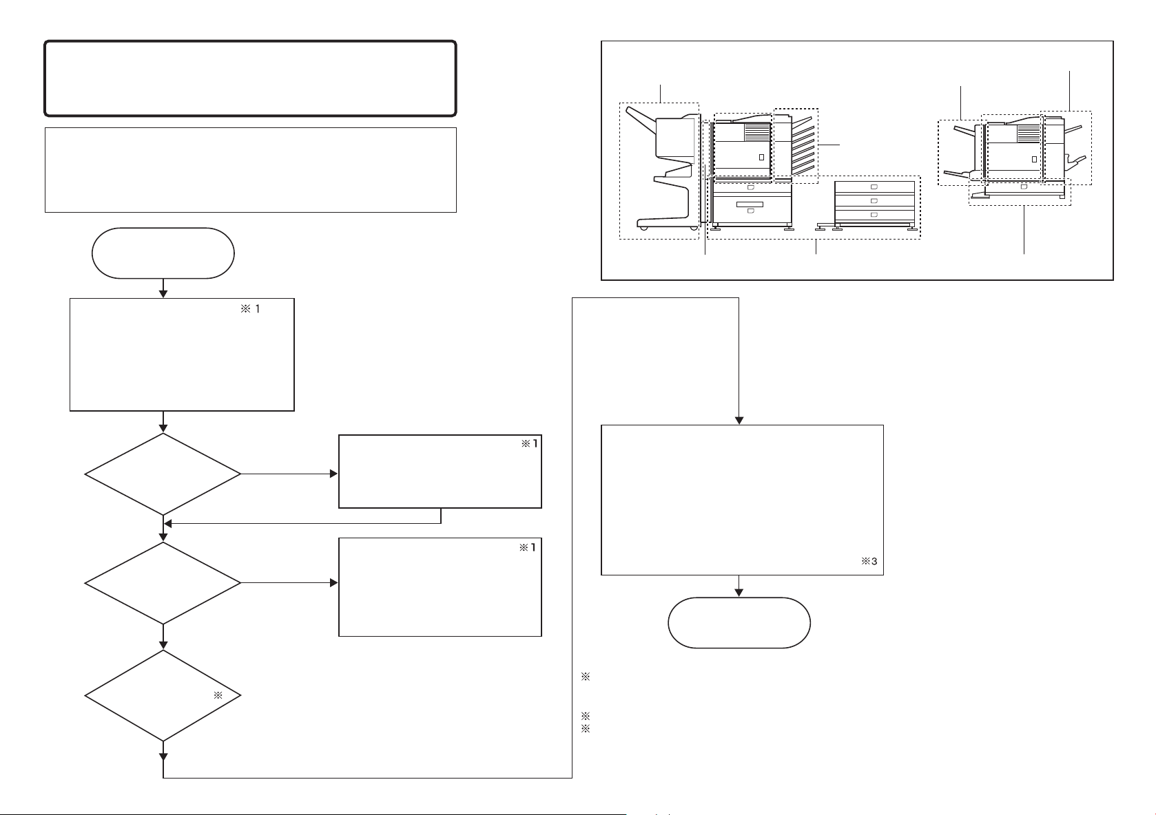
To install the devices efficiently, follow the procedure below.
Some peripheral devices may have been installed as
standard devies depending on the main unit model.
Part of descriptions and illustrations may be different.
Start of installation
Main unit, paper feeding
device, and power supply
unit.
B83MP /
B83LT /
B83TT /
Main unit
Power Suply Unit
Power Suply Unit
Power Suply Unit
.................................. (P. 5)
Duplex/bypass
device installed?
... (P. 2)
..... (P. 3)
.... (P. 4)
Install duplex/pypass device.
Yes
B83D ....................(P. 7)
B83DB ................(P. 8)
Finishing device
Main unit
Paper feeding deviceDuplex device Paper feeding device
[Electrical setting/adjustment]
1) Installation of driver software, setting,
and operation check
Main unit / B83H..............
(P. 13)
Finishing device
Finishing device
Duplex/bypass device
Main unit
No
Finishing device
installed?
No
Hard
Disk
2)
Paper guide position adjustment/off center adjustment
Install finishing device.
Yes
2
B83MB/Power Suply Unit
B83F/Power Suply Unit
B83SS
....................................
B83THP / USP / FHP / FBP.(P. 12)
...
.......
(P. 9)
(P. 10)
(P. 11)
B83MP / B83LT / B83TT /
B83D / B83DB.................(P. 14 & 15)
End
1: When installing a paper feeding device, an optional power supply unit or a duplex/bypass device, be
sure to reattach the rear cabinet, the AC inlet cover, and the harness cover of the main unit at the end
of installation as needed.
2: When installing electrical devices, be sure to install them one at a time.
3: Only off center adjustment is needed for B83D.
Page 3
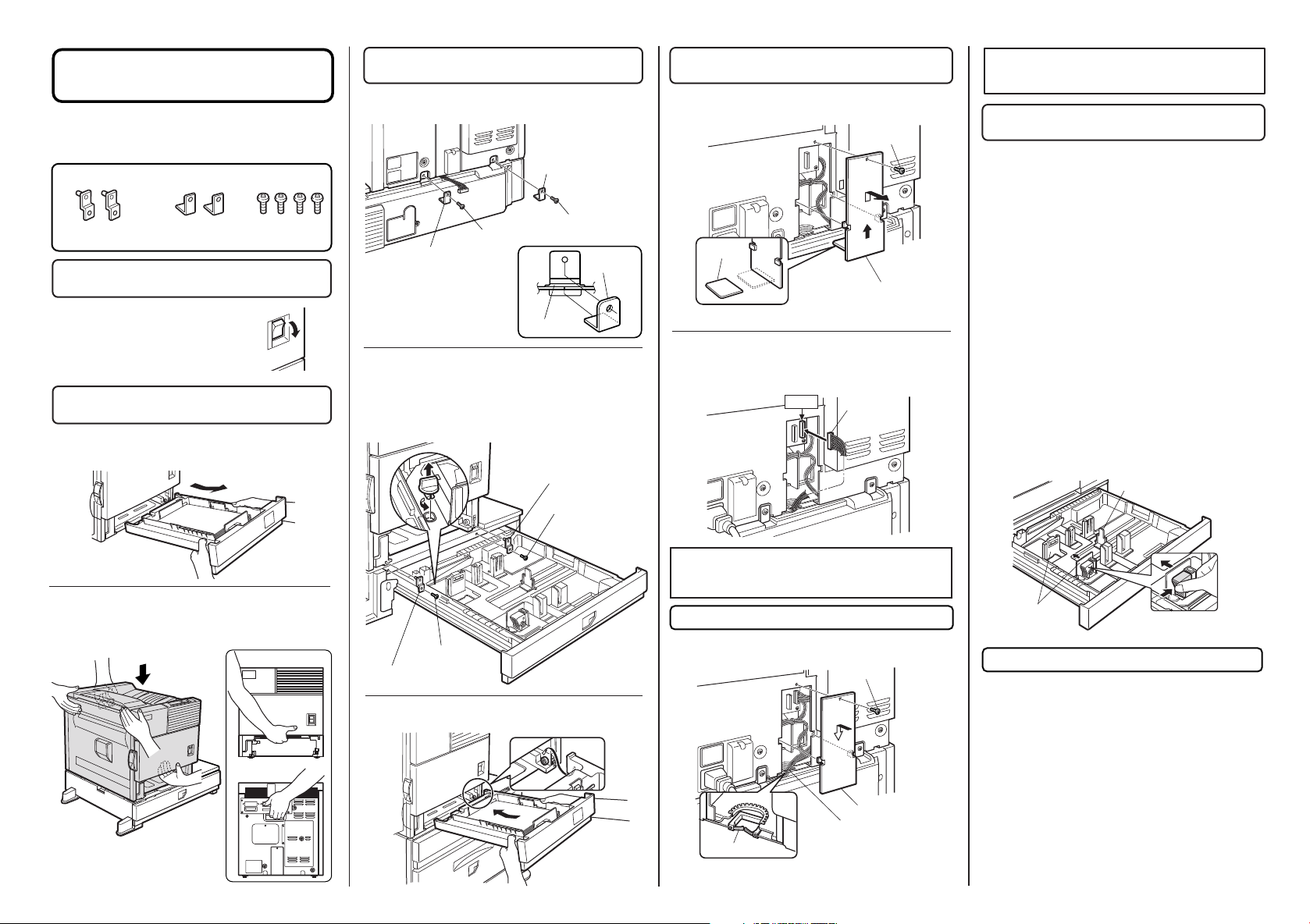
B83MP Installation Manual
FOR USE WITH COMPATIBLE OKI DIGITAL PRINTERS.
SEE OKI DIGITAL PRIN TER S ERVICE MANUA L OR
INSTALLATION MANUAL TO DETERMINE SUITABILITY.
<Before installation>
When installing a finisher or a mail-bin stacker with
B83MP, a power supply unit is needed.
<Parts included>
Front mounting plates:
2 pcs.
Rear mounting plates:
2 pcs.
Screws (M4x8):
4 pcs.
1. Turn off the main switch of the main unit
of the printer.
Turn the main switch located on the
front side of the main unit to the "OFF"
position.
Then, remove the power plug of the
main unit from the outlet.
"OFF"
2. Put the main unit of the printer on the
multi purpose drawer.
<1> Pull out the paper tray of the main unit until it stops
and then remove it by lifting both ends of the tray.
3. Connect the main unit of the printer to the
multi purpose drawer.
<1>Attach the two rear mounting plates using a supplied
screw for each.
Rear mounting plate
Screw
Screw
Rear mounting plate
[Caution]
Insert the mounting plate
under the tray frame.
Tray frame
<2> Pull out the multi purpose drawer until it stops and
attach the two front mounting plates using a supplied
screw for each.
Then, remove the lock of the paper tray and close the
tray.
Mounting
plate
Front mounting plate
Screw
4. Connect the harness to the main unit of
the printer.
<1> Remove the screw that fixes the harness cover of the
main unit of the printer and then slide the harness cover
up to remove it.
Screw
Cut out.
Harness cover
* Cut out the harness cover as shown in the illustration.
<2> Connect the connector of the relay harness of the
multi purpose drawer to CN10 (blue connector) of the
PCU PWB of the main unit of the printer.
CN10
Connector
2
* If another peripheral device must be installed,
carry out the following step at the end of the
installation work.
6. Adjust the position of the paper guides of
the paper tray.
<1> To use the setting mode, insert the power plug of the
main unit of the printer to the outlet and turn the main
switch on while pressing the [MENU] key and the [OK] key
of the operation panel of the main unit of the printer.
<2> Press the [MENU] key several times to display "SIZE
ADJUSTMENT A" and press the [OK] key.
<3> "MAXIMUM SIZE" is displayed.
Pull out the paper tray and extend the paper guides to the
maximum. Then, return the paper tray into the main unit
and press the [OK] key.
<4> "MINIMUM SIZE" is displayed.
Pull out the paper tray again and narrow the paper guides
to the minimum. Then, return the paper tray into the main
unit and press the [OK] key.
<5> Press the [BACK / CLEAR] key to exit the setting
mode.
[Caution]
If the setting above is not carried out, the paper detection
function will not operate.
Rear guide
<2> Hold the main unit of the printer at the positions
shown in the illustration and put the main unit on the multi
purpose drawer so that the front side and the left side of
the main unit are aligned to those of the multi purpose
drawer.
Front side
Rear side
[Caution]
For installation of the main unit, it
must be held by two persons and
installed carefully.
Screw
Front mounting plate
<3> Reattach the paper tray of the main unit of the
printer.
For installation of a finisher or a mail-bin stacker,
see its installation manual.
5. Attach the harness cover.
Reattach the harness cover to its original position and fix it
with the removed screw.
Screw
Harness cover
Wire saddle
Wire saddle
* Fix the harness securely to the wire saddle.
Paper guide
7. Carry out the off center adjustment.
Installation is now complete.
Page 4
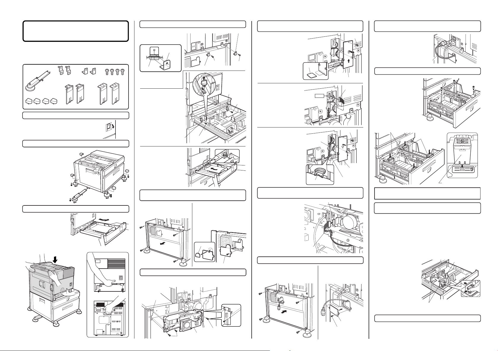
B83LT Installation Manual
FOR USE WITH COMPATIBLE OKI DIGITAL PRINTERS.
SEE OK I DIGI TAL PR INTER SERVICE MANUA L OR
INSTALLATION MANUAL TO DETERMINE SUITABILITY.
<Before installation>
• Start installation after checking that the DATA and
COMMUNICATION indicators on the operation panel are
neither lit nor blinking.
• For installation, a power supply unit is needed.
<Parts included>
Left adjuster: 1 pc.
Adjuster covers: 4 pcs.
Front mounting
plates: 2 pcs.
Left paper guides: 2 pcs. Right paper guides: 2 pcs.
Rear mounting
plates: 2 pcs.
Screws (M4x8):
4 pcs.
1. Turn off the main switch of the main unit of the printer.
Turn the main switch located on the front side of
the printer to the "OFF" position.
Then remove the power plug from the outlet.
"OFF"
2. Attach the adjusters and adjust them.
<1> Insert the left adjusters to
the stand/paper drawer.
<2> Tu rn eac h adj uster to
lower it until it touc hes the floor.
<3> Atta ch the four adjust er
covers.
Be su re to att ach t he le ft
adjuster to prevent overturning.
[Caut ion] The lower tray
cannot be pulled out unles s
the adjuster is lowered to the
specified position.
3
3
2
2
3
1
2
3. Put the main unit of the printer on the stand/paper drawer.
<1> Pull out the paper tray of
the main unit until it stops and
then remove it by lifting both
ends of the tray.
<2> Hold the main unit of the
printer at the positions shown
in the illustration and put the main unit on the
stand/paper drawer so that the front side and the
left side of the main unit are aligned to those of
the stand/paper drawer.
[Caution]
For installation of the main unit, it must be
held by two persons and installed carefully.
Front side
Rear side
4. Connect the main unit to the stand/paper drawer.
<1>A ttac h th e tw o re ar
mount ing plat es u sing a
supplied screw for each.
Rear
mounting plate
Stand frame
[Caution]
Insert the rear mounting
plates under the Stand frame.
<2>Pull out the upper tray
of the stan d/paper d rawer
until it stops, and attach the
two f ront mounting p lates
using a supplied screw for
each.
Then, r emove th e lock of
the paper tray and close the
tray.
Front mounting plate
<3> Reattach the paper tray
of the main unit.
Rear mounting plate
Screw
3
2
5. Remove the rear cabinet of the stand/paper drawer and
remove the AC inlet cover.
<1> Remove the four screws that
fix the r ear cabinet and then
remove the rear cabinet.
Rear cabinet
<2> Remove the screw that fixes the
AC inlet cover and then remove the
AC inlet cover.
<3> Cut out the AC inlet cover as
shown in the illustration.
Cut out.
6. Attach the power supply unit.
Attach the power supply unit to the brackets and secure it using the three
supplied screws.
Bracket
Bracket
Screws
Power supply unit
Rear mounting plate
Screw
Front
mounting plate
AC inlet cover
Screws
Screw
Screw
7. Connect the power supply unit harness to the PCU PWB
of the main unit of the printer.
<1> Rem ove th e screw that
fixes the harness cover of the
main un it of the printer and
slide the harness cover up to
remove it.
Cut out the harness cover as
shown in the illustration.
<2> C onnec t the opti onal
pow er sup ply har nes s
conne ctor t o CN11 (red
connector) of the PCU PWB of
the main unit of the printer.
<3> Reat tach the ha rness
cover to its original position
and fix i t with th e removed
screw.
At this tim e, ensure t hat the
optional power supply harness
are arranged as shown in the
illustration.
• Fix the harness securely to
the wire saddle.
8. Connect the relay harness of the stand/paper drawer to
the power supply unit.
Connect the relay harness of
the stand/paper drawer to the
connector of the power supply
unit.
Relay harness of the
stand/paper drawer
Cut out.
Harness cover
Connector
CN11
Screw
Optional power
supply harness
Harness cover
Wire saddle
Connector of the power supply connector
Wire saddle
9. Attach the rear cabinet of the stand/paper drawer.
<1> Pass the cord of the power supply
unit through the hole of the rear cabinet
and atta ch the rea r cabine t to the
stand/paper drawer.
Rear cabinet
<2> Attach the AC inlet cover
to the rear cabinet of the
stand/paper drawer and fix it
with the removed screw.
AC inlet cover
Screw
Screw
10. Connect the AC cord of the power supply unit to the
main unit of the printer.
Connect t he AC co rd of th e
power supply unit to the inlet
connector of the main unit of
the printer at t he location
shown in the illustration.
AC cord
11. Attach the paper guides to the lower tray.
Remove the four screws for
pack ing. (S ee the righ t
illustration.)
Insert the left paper guides and
right paper guides to the front
and re ar gui de sl ots fo r the
paper size to be used. (See the
illustration below.)
(For the AB system , set t he
guides to A4. For the inch
system, set the guides to LT.)
Left paper guides
Right paper guides
Paper guide
* If another peripheral device must be installed, carry out
the following step at the end of the installation work.
12. Adjust the position of the paper guides of the upper
paper tray of the stand/paper drawer.
<1> To use the setting mode, insert the power plug of the main unit of the
printer to the outlet and turn the main switch on while pressing the [MENU]
key and the [OK] key of the operation panel of the main unit of the printer.
<2> Press the [MENU] key several times to display "SIZE ADJUSTMENT
A" and press the [OK] key.
<3> "MAXIMUM SIZE" is displayed.
Pull out the paper tray and extend the paper guides to the maximum.
Then, return the paper tray into the unit and press the [OK] key.
<4> "MINI MUM SIZE " i s
displayed. Pull out the p aper
tray again and n arrow the
paper guides to the minimum.
Then, return the paper tray into
the unit and press the [OK] key.
(The rear gui de need not be
adjusted.)
[Caution] If the setting above
is not carried out, the paper
detec tion functi on will not
operate.
Paper guides
Rear guide
13. Carry out the off center adjustment.
Installation is now complete.
3
Page 5
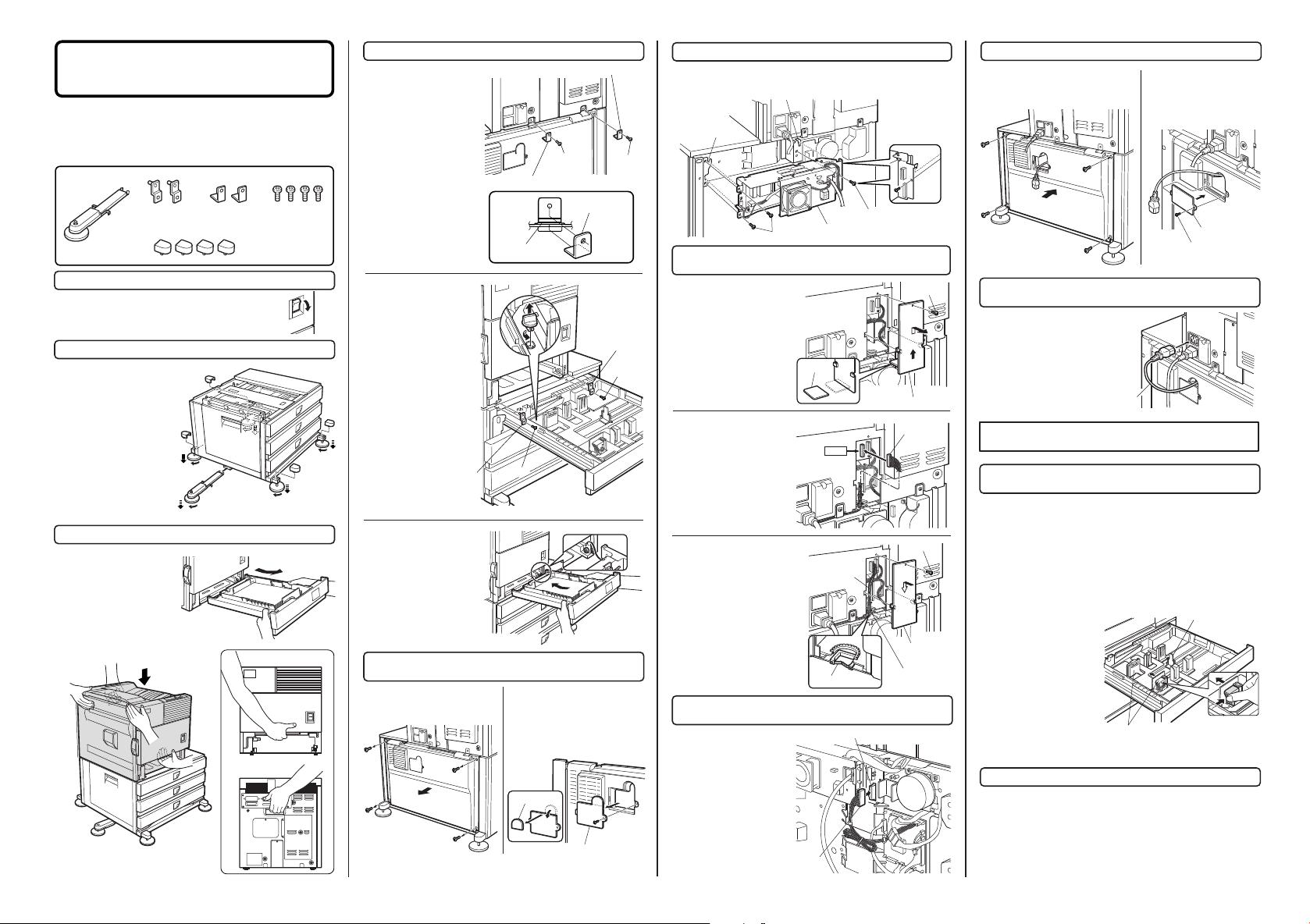
B83TT Installation Manual
FOR USE WITH COMPATIBLE OKI DIGITAL PRINTERS.
SEE OKI DIGI TAL PRINTER SERVICE M ANUAL OR
INSTALLATION MANUAL TO DETERMINE SUITABILITY.
<Before installation>
•
Start installati on after check ing that the DATA and
COMMUNICATION indicators on the operation panel are
neither lit nor blinking.
• For installation, a power supply unit (AR-DC1) is needed.
<Parts included>
Rear mounting
plates: 2 pcs.
Left adjuster: 1 pc.
Front mounting
plates: 2 pcs.
1. Turn off the main switch of the main unit of the printer.
Turn the main switch located on the front side of the
printer to the "OFF" position.
Then remove the power plug from the outlet.
2. Attach the adjusters and adjust them.
<1> Insert the left adjusters to
the stand/paper drawer.
<2> Turn the five adjusters to
lower them until they touch the
floor.
<3> Attach th e four adjust er
covers.
• Be sure to attach the left
adj us ter to pr ev ent
overturning.
[Caution] The lo wer tray
cannot be pulled out unless
the adjuster is lowered to
the specified position.
4
3
2
1
3. Put the main unit of the printer on the stand/paper drawer.
<1> Pull out the paper tray of
the main unit until it stops and
then remove it by lifting both
ends of the tray.
<2> Hold the main unit of the
printer at the positions shown
in the illustration and put the main unit on the
stand/paper drawer so that the front side and
the left side of the main unit are aligned to
those of the stand/paper drawer.
Screws (M4x8):
4 pcs.
Adjuster covers: 4 pcs.
"OFF"
2
3
2
Front side
Rear side
2
4. Connect the main unit to the stand/paper drawer.
Attach the two rear mounting
plate s us ing a suppl ied
screw for each.
Rear mounting plate
[Caution]
Insert the rear mounting plates
under the Stand frame.
Stand frame
<2>Pull out the upper tray of
the stand/paper drawer until
it stops, and attach the two
front mounting plates using
a supplied screw for each.
Then, remove the lock of the
paper tray and close the
tray.
Remove the loc ks of the
middle tray and the lowe r
3
tray similarly.
Front mounting plate
<3> Reattach the paper tray
of the main unit.
5. Remove the rear cabinet of the stand/paper drawer and
remove the AC inlet cover.
<1> Remove the four screws that
fix the r ear cabinet and then
remove the rear cabinet.
Rear cabinet
Screw
<2> Remove the screw that fixes
the AC inlet cover and then remove
the AC inlet cover.
<3> Cut out the AC inlet cover as
shown in the illustration.
Cut out.
Rear mounting plate
Screw
Mounting plate
Front
mounting plate
Screw
Screw
6. Attach the power supply unit.
Attach the power supply unit to the brackets and secure it using the three
supplied screws.
Bracket
7. Connect the power supply unit harness to the PCU PWB
of the main unit of the printer.
<1> Rem ove the screw that
fixes the harness cover of the
main un it of the printer and
slide the harness cover up to
remove it.
Cut out the harness cover as
shown in the illustration.
<2> C onnec t the opti onal
pow er sup ply har nes s
conne ctor t o CN11 (red
connector) of the PCU PWB of
the main unit of the printer.
<3> Re attac h the harness
cover to its original position and
fix it with the removed screw.
At this time, ensure that the
option al powe r suppl y unit
harness is arranged as shown
in the illustration.
• Fix the harness securely to
the wire saddle.
8. Connect the relay harness of the stand/paper drawer
to the power supply unit.
Connect the relay harness of
the stand/paper drawer to the
connector of the power supply
unit.
Bracket
Screws
Screws
Power supply unit
Cut out.
CN11
Optional power
supply harness
Wire saddle
Connector of the power supply connector
Screw
Harness cover
Connector
Screw
Harness cover
Wire saddle
9. Attach the rear cabinet of the stand/paper drawer.
<1> Pass the cord of the power supply
unit through the hole of the rear cabinet
and atta ch the rea r cabine t to the
stand/paper drawer.
Rear cabinet
10. Connect the AC cord of the power supply unit to the
main unit of the printer.
Connect t he AC co rd of th e
power supply unit to the inlet
connector of the main unit of
the printer at t he location
shown in the illustration.
* If another peripheral device must be installed, carry out
the following step at the end of the installation work.
11. Adjust the position of the paper guides of the
upper paper tray of the stand/paper drawer.
<1> To use the setting mode, insert the power plug of the main unit of the
printer to the outlet and turn the main switch on while pressing the [MENU]
key and the [OK] key of the operation panel of the main unit of the printer.
<2> Af ter pr essing the [MENU ] key several times to display "S IZE
ADJUSTMENT A" in the message display and press the [OK] key.
<3> "MAXIMUM SIZE" is displayed.
Pull out the paper tray and extend the paper guides to the maximum.
Then, return the paper tray into the unit and press the [OK] key.
<4> "MINI MUM SIZE " i s
displayed. Pull out the p aper
tray again and n arrow the
paper guides to the minimum.
Then, return the paper tray into
the unit and press the [OK] key.
(The rear gui de need not be
adjusted.)
[Caution]
If the setting ab ove is not
carried out, the paper detection
function will not operate.
<2> Attach the AC inlet cover
to the rear cabinet of the
stand/paper drawer and fix it
with the removed screw.
AC cord
Paper guides
AC inlet cover
Screw
Rear guide
13. Carry out the off center adjustment.
Installation is now complete.
4
[Caution]
For installation of the main unit, it must be
held by two persons and installed carefully.
AC inlet cover
Relay harness of the
stand/paper drawer
Page 6

B8300 Digital Printer
Main Unit Installation Manual
FOR USE WITH COMPATIBLE OKI DIGITAL PRINTERS.
SEE OKI DIGITAL PRINTER S ERVICE MANUAL OR
INSTALLATION MANUAL TO DETERMINE SUITABILITY.
1. Select an installation location.
• Installation requirements
Selection of installation location is important to the performance of the machine. Consider the
following conditions.
• Environment
(1) Avoid locations subject to direct sunlight as plastic parts may be deformed.
(2) Avoid high temperature and high humidity locations or where temperatures change rapidly such as
near a heater or air conditioner. Rapid changes can cause paper to be become damp and condensation
to form within the machine resulting in misfeeds and deterioration of image quality.
Standard conditions: Conditions most adequate for
use of the machine
Acceptable temperature
and humidity range: 20%Å`85%
Max. 60% at 35Åé
Humidity
85
60
20
10 30
35
Temperature
2. Remove the main unit from the carton
(requires two people)
<1> Remove the cushioning materials from the right and
left of the front side.
<2>
Remove the locking
tape from the right and left
sidesof the tray.
Then,
remove the top of
the carton and lower the
plastic bag covering the
machin e whil e
the machine is
still on the carton
base.
<3> Remove the
packin g tape
from the paper
tray, pull out the
paper tray until it
stops and remove
it by tilting it
upward.
One person must lift by the empty front tray pocket with
the right hand and steady the machine with the left hand
placed at the upper left of the machine.
The other person must lift with the right hand by using
the lifting recess in the rear of the machine and also
steady the machine with the left hand as shown in the
illustration.
Front side
4. Install the main unit.
(Be sure to carry out this step after the paper
feeding device has been connected to the main
unit.)
<1> Remove the remainder of packing tape from the
operation panel.
<2> Raise the lever of the left door to unlock it and
open the left door.
<3> Open the front cover.
<4> Rotate the developer unit lock lever down.
5
(3) Avoid a dusty location and a location subject to vibration.
If dust enters the machine, deterioration of image quality or a failure may occur.
(4) Do not install the machine in a location that is not stable.
Be sure to install the machine on a level surface to maintain proper functions.
(5) Avoid poorly ventilated areas.
(6) Avoid areas near combustibles or any ammonia present.
• Space around the machine
Install the machine so that the rear side is at least 30 cm form any wall or other object to allow the
machine’ cooling fan and ventilation to be effective.
Allow sufficient space around the machine for operation and servicing.
• Stand
Ensure that the machine is leveled using a level or the like. If the machine is not placed on a level
surface, the toner density control may not function properly, resulting in poor image quality.
[Caution] If the machine is not placed on a level surface, the toner density control may not function
properly, resulting in bad influence on the quality.
• Grounding
(1) Be sure that the machine is properly grounded.
(2) Use a proper ground such as the grounding terminal on an outlet or according to local grounding
requirements.
Rear side
Caution
Removal of this machine and carrying it must be
always performed by two persons.
3. Check the parts included.
<1> Check that the following items are included with
this machine.
• Drum / Toner cartridge
• Developer cartridge
• CD-ROM
• Safety and Warranty information
• User Guide (may be on CD-ROM)
<5> Remove the protective covering from the
toner/drum cartridge.
<6> Shake the toner/drum cartr idge ho rizontally
approximately 5 times.
Page 7

<7> Insert the toner/drum cartridge into the main unit.
T
E
L
L
I
N
E
<8> Remove the drum protective paper in the direction
indicated by the arrow.
<9>
Remove the supplied developer cartridge from the
packing case and remove the protective materials A and B.
A
B
<10> Shake the developer cartridge horizontally
approximately 5 times and insert it into the machine.
<12> Remove the sealing tape from the developer
cartridge in the direction indicated by the arrow.
<13> Return the developer unit lock to its original
position.
<14> Close the front cover.
Gently close the cover.
<15> Apply pressure to the fusing roller.
Raise the right and left levers of the fusing unit in the
direction indicated by the arrow.
5. Load paper.
<1> Pull out the paper tray.
Gently pull out the paper tray until it stops.
<2> Load paper into the tray.
Do not exceed the maximum height line. (up to 500 sheets
of OKI recommended paper can be loaded)
6.
Connecting the machine to a computer.
<1> Connect the machine to the computer
• When connecting to a parallel port:
The parallel interface of this machine conforms to
IEEE-STD-1284-1983.
Use a commercially available shielded type parallel interface
cable conforming to the specifications of both the machine
and the computer.
The connector on this machine is a 36-pin Amphenol female
connector.
18
1
* If another peripheral device must be installed,
carry out the following step at the end of the
installation work.
<2> Insert the power plug into an outlet.
Caution
If the outlet is also used for lighting fixtures, the lighting
fixtures may flicker.
Use an outlet which is not connected to lighting fixtures.
<3> Turn on the main switch of the main unit.
Automatic level adjustment of toner density sensor will start
and a message indicating [WARMING UP] will appear on
the operation panel. After the level adjustment is complete,
the ready indicator will light up.
Caution
While automatic adjustment of the toner density sensor
is being done, do not turn the power to the machine off.
This will cause improper adjustment.
7. Check the printer operation
For installation of printer drivers on the computer refer to the
Operation manual (for printer operation and general
information) supplied with the machine.
After driver installation, execute a test print to ensure normal
printing.
6
<11> Remove the sealing tape from the toner/drum
cartridge by pulling it in the direction indicated by the
arrow.
<16> Close the left door.
<17> Turn the lock pin a 1/4 turn and remove it while
pressing down on the pressure plate.
Remove the lock pin
while holding down on
the paper pressure
plate and insert the
paper tray into the main
unit.
36
For the specifications of the connector on the computer, see
the operation manual of the computer.
Parallel interface connector
19
Page 8

B83D Installation Manual
"
OFF
"
Hook
Positioning boss
Positioning boss
Hook
Duplex module
FOR USE WITH COMPATIBLE OKI DIGITAL PRINTERS.
SEE OKI DIGITAL PRINTER SERVICE MANUAL OR
INSTALLATION MANUAL TO DETERMINE SUITABILITY.
<Before installation>
•
Carry out the installation after checking that the
DATA indicator on the operation panel is neither lit
nor blinking.
• For installing B83D, an optional desk (multi
purpose drawer, stand/3 x 500 sheet paper drawer
or stand/MPD & 2000 sheet drawer) must have
been installed.
• Ensure that the front mounting plates and the
rear mounting plates included with the optional
stand/paper drawer are securely attached.
•
Check that the left adjuster supplied with an
optional stand/drawer has been attached.
1. Turn off the main switch of the main unit of the printer.
Turn the main switch located on
the front side of the main unit of
the printer to the "OFF" position.
Then, remove the power plug of
the main unit of the printer from
the outlet.
Parts included
M4 Screws
(M4x8) : 1 pcs.
3.
Attach the duplex module to the main unit of the printer.
<1> Hang the hooks located at
the upper part of the duplex
module on the openings of the
left door of the main unit of the
printer.
<2> Push the lower part of the
duplex module to insert the
positioning bosses securely
into the main unit of the printer.
<3> Tighten the two screws
built in the duplex module.
4. Connect the harness to the main unit of the printer.
<1> Remove the screw that
fixes the harness cover of the
main unit of the printer and
then slide the harness cover
up to remove it.
<2> Cut out the harness cover
as shown in the illustration.
Harness cover
Screw
Harness cover
<6> Reattach the harness
Harness cover
cover to its original position
and fix it with the removed
screw.
Relay harness
* If another peripheral device must be installed, carry out
the following step at the end of the installation work.
5. Carry out the off center adjustment.
Installation is now complete.
7
Screw
Unlock the lock release
lever of the main unit of the
printer and then pull out the
left door.
Slide the two upper covers
up to remove them. Remove
the lower cover by inserting
a flat-blade screwdriver at
three locations ( ) shown in
the illustration.
Then, close the left door.
2.
Remove the left side cover of the main unit of the printer.
Top covers
Left door
Lower cover
Lock release lever
<3> Connect the connector of
the relay harness of the
duplex module to the CN12
(white connector) of the PCU
PWB of the main unit of the
printer.
<4> Insert the snap bands to
the locations shown in the
illustration and fix them.
<5>Secure the earth harness
using a supplied M4 screw.
Cut out.
Relay harness
connector
Snap bands
CN12
M4 Screw
PCU PWB
Ground harness
Page 9

B83DB Installation Manual
"
OFF
"
Hook
Positioning boss
Positioning boss
Hook
Duplex module
FOR USE WITH COMPATIBLE OKI DIGITAL PRINTERS.
SEE OKI DIG ITAL PRINTER SERVICE MANUAL O R
INSTALLATION MANUAL TO DETERMINE SUITABILITY.
<Before installation>
• Carry out the installation after checking that
the DATA indicator on the operation panel is
neither lit nor blinking.
• For installing B83DB, an optional desk (multi
purpose drawer, stand/3 x 500 sheet paper
drawer or stand/MPD & 2000 sheet drawer)
must have been installed.
• Ensure that the front mounting plates and
the rear mounting plates included with the
optional stand/paper drawer are securely
attached.
• Check that the left adjuster supplied with an optional stand/drawer
has been attached.
1. Turn off the main switch of the main unit of the printer.
Turn the main switch located on the front side of the
main unit of the printer to the "OFF" position.
Then, remove the power plug of the main unit of the
printer from the outlet.
2.
Remove the left side cover of the main unit of the printer.
Unlock the lock release lever of the
main unit of the printer and then pull
out the left door.
Slide the two upper covers up to
remove them. Remove the lower
cover by inserting a flat-blade
screwdriver at three locations ( )
shown in the illustration.
Then, close the left door.
3.
Attach the duplex module to the main unit of the printer.
<1> Hang the hooks located at
the upper part of the duplex
module on the openings of the
left door of the main unit of the
printer.
<2> Push the lower part of the
duplex module to insert the
positioning bosses securely into
the main unit of the printer.
<3> Tighten the two screws built
in the duplex module.
Top covers
Lower cover
Lock release lever
Left door
Parts included
Exit tray
M4 Screws :
1 pcs.
4. Connect the harness to the main unit of the printer.
<1> Remove the screw that
fixes the harness cover of the
main unit of the printer and
then slide the harness cover
up to remove it.
<2> Process the harness cover
as shown in the illustration.
<3> Connect the connector of
the relay harness of the
duplex module to the CN12
(white connector) of the PCU
PWB of the main unit of the
printer.
<4> Insert the snap bands to
the locations shown in the
illustration and fix them.
<5>Secure the earth harness
using the supplied M4 screw.
<6> Reattach the harness cover
to its original position and fix it
with the removed screw.
Harness cover
Cut out.
Relay harness
connector
Snap bands
CN12
M4 Screw
Harness cover
Relay harness
Screw
Harness cover
PCU PWB
Ground harness
Screw
5. Attach the exit tray.
* If another peripheral device must be installed, carry out
the following step at the end of the installation work.
6.
Adjust the position of the paper guides of the bypass tray.
<1> To use the setting mode, insert the power plug of
the main unit of the printer to the outlet and turn the
"ON"
main switch on while pressing the [MENU] key and
the [OK] key of the operation panel of the main unit of
the printer.
<2> After pressing the [MENU] key several times to
display "SIZE ADJUSTMENT A" in the message
display, press the [ ] key to display "SIZE ADJUSTMENT B" and press the
[OK] key.
<3> "MAXIMUM SIZE" is displayed.
Since "MAXIMUM SIZE" is displayed with a number, press the [ ] key or the
[ ] key to change the number so that the number is equal to the value of
[MAX] written on the label
( NOTE)
and then press the [OK] key.
<4> Since "P1 SIZE" is displayed with a number, press the [ ] key or the [ ]
key to change the number so that the number is equal to the value of [P1]
written on the label
( NOTE)
and then press the [OK] key.
<5> Since "P2 SIZE" is displayed with a number, press the [ ] key or the [ ]
key to change the number so that the number is equal to the value of [P2]
written on the label
( NOTE)
and then press the [OK] key.
<6> Since "MINIMUM SIZE" is displayed with a number, press the [ ] key or
the [ ] key to change the number so that the number is equal to the value of
[MIN] written on the label
( NOTE)
and then press the [OK] key.
[Caution]
If the setting above is not carried out, the paper detection function will not
operate.
( NOTE)
Illustration of label sticking position
(Back surface of the bypass tray
extension)
Label
MAX MINP1 P2
7. Carry out the off center adjustment.
Installation is now complete.
8
Page 10

B83MB Installation Manual
CN11
FOR USE WITH COMPATIBLE OKI DIGITAL PRINTERS.
SEE OKI DIGITAL PRINTER SERVICE MANUAL OR
INSTALLATION MANUAL TO DETERMINE SUITABILITY.
<Before installation>
• Start installation after checking that the DATA and
COMMUNIC ATION indicators on the operation panel are
neither lit nor blinking.
• For installation of B83MB, an optional stand/paper drawer
(stand/MPD & 2000 sheet paper drawer, stand/3 x 500 sheet
paper dr awer or multi purpos e drawer ) must h ave been
installed.
Also if a multi purpose drawer has been installed, a power
supply unit is needed additionally.
<Parts included>
Mounting plates: 2 pcs.
Tray: 1 pc.
Screws A (M4x8): 5 pcs.
Screw B: 1 pc.
1. Turn off the main switch of the main unit of the printer.
Turn the main switch located on the front side of the
main unit to the "OFF" position.
Then, remove the power plug of the main unit from the
outlet.
"OFF"
2. Remove the upper cabinet of the stand/paper drawer.
<1> Pull out the paper tray of
the stand/paper drawer.
Remove the four sc rews of
the ca binet attached t o the
right side of the main unit of
the p rinter and rem ove t he
cabinet.
Cabinet
<3> Hold the grip of the mailbin stacker and place the mailbin stacker on the stand/paper
drawer temporarily.
Then, push the lower part to
attach the mail-bin stacker by
sliding it toward the exit tray of
the main unit.
At this time, align the mail-bin
stacker with the exterior line of
the stand/paper drawer.
<4> Open the front cover of the
mail-b in stacker and fix th e
stacker with three screws A at
the pos itions shown in the
illustration.
Then, close the front cover and
close the pap er t ray o f the
stand/paper drawer.
(Front side)
Screw A
Screw A
4. Attach the tray.
Place.
Grip
<5> Attach the mounting plates to
the pos ition s shown in the
illust ration and fix them with
screws A.
(Rear side)
Mounting plate
Stand frame
[Caution ] Inse rt the mount ing
plate under the desk frame.
Grip
Push.
Screws A
Mounting plate
Push.
6. Attach the power supply unit.
Attach the power supply unit to the brackets and secure it using the
supplied three screws.
Bracket
Ç–Ç¡Ç©ÇØïî
7. Connect the power supply unit harness to the PCU PWB
of the main unit of the printer.
<1> Remov e the scr ew that
fixes the harness cover of the
main unit of the printer and
slide the harness cover up to
remove it.
<2> Connect the power supply
unit har ness con nector to
CN11 (red connector) of the
PCU PWB of the main unit of
the printer.
Bracket
Screws
Screw
Optional power supply unit
Screw
Harness cover
Connector
<2> Remove the AC cord of
the power supply unit from the
inlet connector of the main unit
of the printer.
Remove the four screws that
fix the rear cabinet and then
remove the rear cabinet.
Rear cabinet
(* Similar work for the multi purpose drawer)
9. Arrange the harness of the mail-bin stacker.
<1> Pass the harness of the
mail-bin stacker be tween the
power s upply unit and th e
frame o f the stand/ paper
drawer and connect it to the
connector of the power supply
unit.
<2> Fit t he s nap band
attac hed to the mail -bin
stacker at the position shown
in the illustrati on to fix the
harness.
(* Similar work for the multi purpose drawer)
Snap band
Mail-bin stacker harness
10. Attach the rear cabinet of the stand/paper drawer.
<1> Pass the AC cord of the pow er
supply unit as shown in the illustration
and f ix t he re ar c abine t of the
stand/paper drawer with the screws.
<2> Attach the AC inlet cover
to the r ear cabinet of the
stand/paper drawer and fix it
with the removed screw.
Power supply
unit connector
9
<2> Mount screw B to the
posit ion shown i n t he
illustration.
3. Attach the mail-bin stacker.
<1> Remove the paper exit
actuator from the main unit
of the printer.
<2> Raise the relay unit at the
side of the mail-bin stacker.
[Caution]
Do not press on the relay unit
while it is raised.
(Doing so may deform or
damage the unit.)
Relay unit
Screw B
Actuator
Tray
Steps 5 and after are the procedure to be carried out when a
multi purpose drawer has been installed.
If a stand/MPD & 2000 sheet paper drawer or a stand/3 x 500
sheet paper drawer has been installed, carry out steps 8 and
after.
5. Process the AC inlet cover attached to the rear cabinet
of the stand/paper drawer.
Remove the two screws that
secure the rear cabinet and
remove the rear cabinet.
Remove the screw that fixes
the AC inlet cover and then
remove the AC inlet cover.
Screw
Process the AC inlet cover as
shown in the illustration.
Screw
Cut out.
AC inlet cover
Screw
Rear
cabinet
<3> Re attach the harness
cover to its or iginal positi on
and fix it with the removed
screw.
At this time, ensure that the
power supply unit harness is
arrange d as shown in the
illustration.
• Fix the harness securely to
the wire saddle.
8. Remove the AC inlet cover and then remove the rear
cabinet of the stand/paper drawer.
<1> Remo ve the screw that
fixes the AC inlet cover and
then remove the A C inlet
cover.
Optional power
supply harnesses
Wire saddle
Wire saddle
AC inlet cover
(* Similar work for the multi purpose drawer)
Screw
Screw
Harness cover
Rear cabinet
Screw
AC inlet cover
(* Similar work for the multi purpose drawer)
11. Connect the AC cord of the optional power supply unit
to the main unit of the printer.
<1> Connect the AC cord of
the power supply unit to the
inlet connector of the main unit
of the printer a t the location
shown in the illustration.
AC cord
(* Similar work for the multi purpose drawer)
Installation is now complete.
Page 11

B83F Installation Manual
CN11
FOR USE WITH COMPATIBLE OKI DIGITAL PRINTERS.
SEE OKI D IGITAL P RINTER S ERVICE M ANUAL O R
INSTALLATION MANUAL TO DETERMINE SUITABILITY.
<Before installation>
• Star t installation after che cking that t he DATA an d COMMUNICATIO N
indicators on the operation panel are neither lit nor blinking.
• For installation of B83F, an optional stand/paper drawer (stand/MPD & 2000
sheet paper drawer, stand/3 x 500 sheet paper drawer or multi purpose drawer)
must have been installed.
Also if a multi purpose drawer has been installed, a power supply unit is
needed additionally.
<Parts included>
Tray 1: 1 pc.
Tray 2: 1 pc.
Screws A (M4x8): 5 pcs.
Screw B: 1 pc.
Mounting plates: 2 pcs.
Stapling position labels:
2 sheets
Staple cartridge: 1 pc.
1. Turn off the main switch of the main unit of the printer.
Turn the main switch located on the front side of the
main unit to the "OFF" position.
Then, remove the power plug of the main unit from
the outlet.
"OFF"
2. Remove the upper cabinet of the stand/paper drawer.
<1> Pull out the tray of the
stand/paper drawer.
Remo ve t he four scre ws
attached to the right on the top of
the stan d/pape r drawer and
remove the cabinet.
<2> Mount s crew B to th e
posit ion s hown in t he
illustration.
Cabinet
Screw B
<3> Hold the grip of the finisher
and place th e f inisher on t he
stand/paper drawer temporarily.
Then, push the lo wer part to
attach the f inisher by sl iding it
toward the exit tray of the main
unit.
At this time, align the finisher with
the exter ior lin e of the
stand/paper drawer.
Grip
<4> Open the front cover of the
finisher and fix the finisher with
three screws A at the positions
shown in the illustration.
Then, close th e fr ont cover and
close the p aper tray o f the
stand/paper drawer.
(Front side)
Screws A
Screws A
<5> Attach the mounting plates to the
positions shown in the illustration and
fix them with screws A.
Mounting plates
Stand frame
[Caution] Insert the moun ting plate
under the desk frame.
4. Insert the staple cartridge.
<1> Pull out the staple unit.
<2> Remove the sealing tape from the staple cartridge.
<3> Insert the staple cartridge.
<4> Slide the release lever to the left and return the staple unit.
Place.
(Rear side)
Push.
Mounting plate
Grip
Push.
Screws A
Steps 6 and after are the procedure to be carried out when a multi
purpose drawer has been installed.
If a stand/MPD & 2000 sheet paper drawer or a stand/3 x 500 sheet
paper drawer has been installed, carry out steps 9 and after.
6. Process the AC inlet cover attached to the rear cabinet
of the stand/paper drawer.
AC inlet cover
AC inlet cover
Screw
Rear
cabinet
Screw
Remove the two screws that
secure the rear cabinet and
remove the rear cabinet.
Remove the screw that fixes the
AC inlet cover and then remove
the AC inlet cover.
Process the AC inlet cover as
shown in the illustration.
Screw
Cut out.
7. Attach the power supply unit.
Attach the power supply unit to the brackets and secure it using the supplied
three screws.
Bracket
8. Connect the power supply unit harness to the PCU PWB
of the main unit of the printer.
<1> Remove the screw that fixes
the harness c over of the mai n
unit of the printer and slide the
harness cover up to remove it.
Process the harness cover as
shown in the illustration.
Bracket
Screws
Screws
Optional power supply unit
Screw
10. Remove the AC inlet cover and then remove the rear
cabinet of the stand/paper drawer.
<1> R emove the screw that
fixes the AC inlet cover an d
then remove the AC inlet
cover.
AC inlet cover
Screw
<2> Remove the AC cord of the power
supply unit from the inlet connector of the
main unit of the printer.
Remove the four screws that fix the rear
cabinet and then remove the rear cabinet.
Rear cabinet
(* Similar work for the multi purpose drawer)
10. Arrange the harness of the finisher.
<1> Pass the harness of the
finis her betwe en the power
supply unit and the frame of the
stand/paper drawer and connect
it to the connector of the power
supply unit.
<2> Fit the snap band attached to
the finisher at the position shown
in the illustra tion to fix the
harness.
(* Similar work for the multi purpose drawer)
Snap band
Finisher harness
Power supply unit
connector
11. Attach the rear cabinet of the stand/paper drawer.
<1> Pass the AC cord of the power supply
unit as shown in the illustration and fix the
rear cabinet of the stand/paper drawer with
the screws.
Rear cabinet
<2> Attach the AC inlet cover to
the rear ca binet o f the
stand/pap er dr awer and fix it
with the removed screw.
10
3. Attach the finisher.
<1> Remove the pa per exit
actuator from the main unit of
the printer.
<2> Raise the relay unit at the
side of the finisher.
[Caution]
Do not press o n the relay un it
while it is raised.
(Doing so may deform or damage
the unit.)
Relay unit
Actuator
5. Attach the trays .
Attach tray 1 and tray 2 to
the positions sh own in the
illustration.
Tray 1
Tray 2
<2> Connect th e power suppl y
unit harness connector to CN11
(red connector) of the PCU PWB
of the main unit of the printer.
<3> Reattach the harness cover
to its original position and fix it
with the removed screw.
At this time, ensur e that the
power suppl y unit harness is
arran ged as sho wn in t he
illustration.
• Fix the harness securely to the
wire saddle.
Optional power
supply harnesses
Wire saddle
Wire saddle
Harness cover
Connector
Screw
Harness cover
Wire saddle
Screw
AC inlet cover
(* Similar work for the multi purpose drawer)
12.
Connect the AC cord of the optional power supply unit
to the main unit of the printer.
<1> Connect the AC cord of
the power supply unit to the
inlet connector of the main
unit of the printer at the
locat ion sho wn in the
illustration.
AC cord
Installation is now complete.
Page 12

B83SS Installation Manual
FOR USE WITH COMPATIBLE OKI DIGITAL PRINTERS.
SEE OKI D IGITAL P RINTER S ERVICE M ANUAL O R
INSTALLATION MANUAL TO DETERMINE SUITABILITY.
<Before installation>
For inst allat ion of B8 3SS, an op tiona l stand /paper drawer
(stand/MP D & 20 00 shee t drawer or st and/3 x 500 sheet paper
drawer) and a duplex module B83D must have been installed. Also a
power supply unit is needed.
<Parts included>
Lock securing plate:
1 pc.
Staple unit: 1 pc.
Stapling position labels:
2 sheets
Rear grounding
plate: 1 pc.
Screws C
(M4x18):
7 pcs.
Connecting plate:
1 pc.
Screws D
(M4x10 with rosette):
1 pcs.
Front cover:
1 pc.
Screws A
(M4x6):
6 pcs.
Plate R: 1 pc.
Front grounding
plate: 1 pc.
Screws B
(M4x10):
2 pcs.
1. Turn off the main switch of the main unit of the printer.
Turn the main switch located
on the front side of the main
unit to the "OFF" position.
Then remove the power plug
of the main unit from the outlet.
"OFF"
2. Attach the lock securing plate to the duplex module.
<1> Remove the screw from the
right side of the duplex module.
<2> A ttach the lock secu ring
plate to th e du plex module
using the screws C and D (one
for each).
Screw
Screw D
Screw C
Lock securing plate
3. Work the stand/paper drawer.
Open the pawl of the left
adjuster to both sides to unlock
it that is located at the lower left
of the stand/paper drawer and
remove the left adjuster.
Pawl
Mounting
holes
Mounting
holes
Cut out the two mounting holes
of the stand/paper drawer using
a screwdr iver or the like and
remove burrs using a flat-blade
screwdriver or the like.
Left adjuster
4. Attach the grounding plate to the stand/paper drawer.
Remove the two screws
that fix the ex terior o f
the stand/paper drawer.
Then, attach t he fr ont
mounting plate and the
rear mount ing plate to
the stand/paper drawer
using screws C (two for
each).
Exterior
fixing screw
Screws C
Rear grounding plate
Exterior
fixing screw
Screws C
Front grounding plate
5. Install the staple unit to the finisher.
<1> Remo ve the t wo piece s of
packing ta pe from the location s
shown in the illustration.
Packing tape
Packing tape
<2> Open the front cover of the
finisher and insert the staple unit.
6. Attach the cover to the finisher.
<1> Attach the plate R to
the position show n in the
illustr ation and secure it
using two screws A.
<2> Attach the front cover
to the finisher, and secure
the upp er part using two
screws B and the lower
part using two screws A.
Front cover
Screws B
Screws A
Screws A
7. Connect the finisher to the stand/paper drawer.
<1> Remove the cover from
the finisher stand.
<2> Attac h the connectin g
plate to the finisher using two
screws A.
<3> Reattach the cover to its
original position.
Screws A
Cover
Finisher stand
Connecting plate
Plate R
<4> Cut out t he two moun ting
holes for the connecting plate at
the lower part of the stand/paper
drawer in a similar way to step 3.
<5> Attac h th e fi nis her
conn ecting plat e to the
stand/pa per drawer using two
screws C.
Screws C
Stand/paper drawer
Connecting plate
8. Check and adjust the height of the finisher.
Move the finisher toward the printer
and check to see if the guide pin of
the lock ing pla te is inser ted
smoothly to the connecting hole of
the finisher.
If it is not inserted smoothly, use
the following proced ure to adjust
the height.
1. If the guide pin of the lock securing plate is not aligned with the
connecting hole of the finisher:
<1> Loosen the scre w at
the rear adjusting portion.
<2> Remove the cap using
a flat-blade screwdriver or
the l ike a nd ad just t he
height adjusting pin so that
the guide pin is positioned
to the cente r of th e
connec ting ho le of th e
finisher.
<3> Loosen the scre w at
the front adjusting portion.
<4> Adjust t he height
adjusting pin so that the
exterior lines are align ed
as shown in the illustration.
<5> If the guide pin can be
inserted smo othly, tighte n
the screws at the front and
rear adjusting portions and
mount the caps.
2. If the guide pin of the locking plate matches to the connecting hole
of the finisher:
<1>Push the finisher into the
main unit.
<2>If the g ap between the
main unit of the print er and
the finisher is not uniform at
the top and th e bott om,
remove the cap s from the
front side and the rear side of
the finisher stand using a flatblade screwdriver or the like
and remove the screw of the
sub covers on the front side
and the rear side to remove
the sub covers.
<3>The n, loosen the four
screw s at the adj usti ng
porti ons indica ted in the
illustration and turn the height
adjusting screws on the front
side and the rear side so that
the gap becomes uniform.
Front side
Screw at
adjusting
portion
Screw at adjusting portion
Exterior lines
Front cover
Exterior lines
Height adjusting
screw
Finisher stand
Cap
Height
adjusting
screw
Connecting
hole
Guide pin
Cap
Rear side
Gap
Gap
<4>If the gap beco mes uniform, tight en the screws at the adjusting
portions and reattach the caps and sub covers.
Cap
Sub cover
Screw
Screw at adjusting portion
Rear side
Height
adjusting screw
Screw
Cap
Sub cover
Front side
Screw at adjusting portion
9. Paste the stapling position labels.
Paste the labels to the positions
shown in the illustration.
10. Remove the AC inlet cover from the rear cabinet of the
stand/paper drawer.
Remove the screw that fixes
the AC inlet cover and then
remove the AC inlet cover.
AC inlet cover
Screw
11. Connect the finisher connector.
<1> C onnec t the fini sher
connector to the stand/paper
drawer.
<2> Tighten the screw of the
connector.
Screw
Connector
12. Turn on the main switch of the main unit.
Insert the power plug of the
main unit to the outlet.
Turn on the main switch of the
main unit.
Installation is now complete.
"ON"
11
Page 13

Screws
Connector
AC cord
Screws B
Screws A
Front cover
B83THP / USP / FHP / FBP
Installation Manual
FOR USE WITH COMPATIBLE OKI DIGITAL PRINTERS.
SEE OKI D IGITAL P RINTER S ERVICE MA NUAL OR
INSTALLATION MANUAL TO DETERMINE SUITABILITY.
<Before installation>
For installation of B83THP / USP / FHP / FBP, a saddle stitch
finisher B83SS must have been installed.
Parts included
Harness A (purple): 1 pc.
Screw
(M4 x 6 with rosette)
: 1 pc.
Dust box label:
1 sheet
1. Turn off the main switch of the main unit of the printer.
Turn the main switch located
on the front side of the main
unit to the "OFF" position.
Then remove the power plug
of the main unit from the outlet.
Loosen the screw and remove
the connector of the finisher.
2.
Remove the front cover from the right front of the finisher.
Remove the screws A and B
(two for each) that secure the
finis her fro nt cover a nd
remove the front cover.
3. Remove the front cabinet and the rear cabinet from
the finisher.
<1> Open the front
door of the finisher and
rem ove t he jam
handling dial.
Harness B (orange): 1 pc.
Hole punch position label:
"OFF"
Jam handling dial
2 sheets
Screws
Connector
<2> Remove the fou r fr ont
cabinet securing screws, pull
out the staple unit until it stops,
then remove the pawl of the
front cabinet in the direction
indicate d by the arr ow an d
remove the front cabinet.
<3> Remove the three screws
that fix the rear cabinet and
remove the rear cabinet.
At this time, remove the relay
harness through the opening
of the rear cabinet.
<4> Rem ove the three rear
cabi net sec urin g scre ws,
remov e t he pawl in t he
direct ion ind icate d by the
arrow, a nd remov e the re ar
cabinet.
At this time, remove the relay
harness through the opening
of the rear cabinet.
Screw
Staple unit
Screws
Pawl
Front cabinet
Screws
Pawl
Rear
cabinet
Screw
Opening for
relay harness
Relay harness
4. Remove the top cover.
<1> Rem ove the four top cover
securing screws and remove the top
cover.
Screws
Top cover
<2> Remove the four pa wls
from the top c over and
separat e the cove r into the
upper an d l ower port ions.
Reuse the upper portion.
Pawl
Top cover
Pawl
5. Attach the punch module.
<1> Insert the two bosses of the punch unit into the boss holes of the
finisher and fix the punch module using three screws.
(Note)
For the screws, use a supplied screw and the two screws that have been
removed in step 4.
Boss hole
Boss
Screw
Punch module
Screw
Screw (with rosette) (supplied with this module)
Boss
Boss hole
6. Connect the harness of the punch module to the PWB
of the finisher.
Remove th e clamps that fix
the harness, handle the wiring
of harn ess A (purple ) and
harness B (orange) , and fix
them with the clamps.
Harness B (orange)
Harness A (purple)
Clamps
Harness B (orange)
Clamps
Harness A (purple)
7. Reattach the covers that have been removed.
<1> Hang the tw o pawls of
the to p cove r and secure
them using the two screws.
<2> Pass the relay harness to
the rear cabinet and se cure
the rear cabin et using the
three screws.
<3> Remove the lock release
lever that has been attached
to the front cabinet.
Reattach the front cabinet to
its origina l position, p ush in
the staple unit, and attach it
using the two screws.
Insert the protrusion (B) of the
lock release lever t hat has
been removed before to the
hole (C) of the latch arm.
After at taching i t, move the
lever to check that it moves
smoothly.
If the lever doe s not move
smoothl y, remov e the lock
release lever by releasing the
pawl at the lower part of the
lock release lever using a flatblade screwdriver or the like
and then insert it again.
Staple unit
Screws
Front cabinet
Pawl
Screws
Screw
Top cover
Latch arm
Lock release lever (A)
Projection (B)
Opening for
relay harness
Relay harness
Screw
Rear cabinet
Screw
Pawl (D)
(C)
<4> Re atta ch the jam
handling dial and close the
front cover.
Jam handling dial
8. Reattach the front cover to the right front of the finisher.
Attach the front cover using
the screws A and B (two for
each).
Front cover
Screws B
Screws A
9. Paste the dust box label to the top cover.
Paste the supplied dust bo x
label to the location indicated
in the illustration.
10. Connect the connector to the stand/paper drawer and
connect the AC cord of the power supply unit to the
main unit of the printer.
Connect the connector of the
relay harness of the finisher to
the sta nd/paper drawer and
tighte n th e s crews of the
connector.
Installation is now complete.
12
Page 14

"OFF"
"ON"
Screws
Grip
Grip
Screws
Screws
B83HD Installation Manual
FOR USE WITH COMPATIBLE OKI DIGITAL PRINTERS.
SEE OKI DIGITAL PRINTER SERVICE MANUAL OR
INSTALLATION MANUAL TO DETERMINE SUITABILITY.
<Before installation>
• Start installation after checking that the DATA and
COMMUNICATION indicators on the operation panel are
neither lit nor blinking.
Parts included
PWB fixing screws: 3 pcs.
Grounding plate
: 1 pcs.
1. Turn off the main switch of the main unit of the printer.
Turn the main switch
located on the front
side of the main unit to
the "OFF" position.
Then remo ve the
power plug from the
outlet.
2. Remove the cables connected to the control PWB unit.
Remove all the cables connected to the control PWB unit of the main unit of the
printer.
• In case of printer control PWB
• In case of MFP control PWB
screws: 1 pcs.
"OFF"
3. Remove the control PWB unit.
Remove the five screws that
fix the control PWB unit to
the main unit of the printer.
Then, hold the two grips and
pull out the printer control
PWB unit to remove it from
the main unit.
(Example) MFP control PWB
4. Mount the HDD expansion PWB to the control PWB.
• The procedure (shape of PWB) varies with the printer control PWB and
the MFP control PWB.
• In case of printer control PWB ..................................................................................
<1> Remove the screw at the position shown in the
illustration among the screws that secure the hard
disk to the HDD expansion PWB.
<2> Attach the supplied grounding plate to the HDD
PWB as shown in the illustration
and secure it using the screw that
has been removed in step <1>.
<3> Remove the three screws
shown in the illustration among
the screws that fix the printer
control PWB.
<4> Mount supplied three PWB
fixing screws to the positions from
which three screws have been
removed.
<5> Insert the HDD expansion
PWB to the connector of the
printer control PWB.
<6> Fix the HDD expansion PWB
to the PWB fixing screws using
the three screws that have been
removed in step 1.
<7> Secure the grounding plate that
has been attached to the HDD
expansion
PWB to the controller mounting
plate using the supplied screw.
• In case of MFP control PWB ......................................................................................
<1> Remove the three screws
shown in the illustration among
the screws that fix the MFP
control PWB.
<2> Mount supplied three PWB
fixing screws to the positions from
which three screws have been
removed.
<3> Insert the HDD expansion
PWB to the connector of the MFP
control PWB.
<4> Fix the HDD expansion PWB
to the PWB fixing screws using
the three screws that have been
removed in step 1.
HDD expansion PWB
HDD expansion PWB
5. Attach the control PWB.
Attach the control PWB unit to
the main unit of the printer and
fix it using five screws.
(Example) MFP control PWB
6. Connect the cables to the control PWB.
Connect all the cables that have been removed in step 2 to the original positions
of the printer control PWB unit.
• In case of printer control PWB
• In case of MFP control PWB
* If another peripheral device must be installed, carry out
the following step at the end of the installation work.
7. Turn on the main switch of the main unit of the printer.
Insert the power plug of the
main unit of the printer to the
outlet.
Then, turn the main switch
located on the front side of the
main unit to the "ON" position.
"ON"
8. Check the operation.
• For setting change of the printer drivers on the computer, see the supplied
operation manual.
Then, execute printing from the computer using the print hold function to check
for proper printing.
13
Page 15

Electrical Setting/ Adjustment/ Operation Check
[1]Installation of driver software,
setting, and operation check
Applied model: Main unit
•
Carry out installation of driver software and check
of printing
<1> Insert the power plug into an outlet.
Caution
If the outlet is also used for lighting fixtures, the lighting
fixtures may flicker.
Use an outlet which is not connected to lighting
fixtures.
<2> Turn on the main switch of the main unit.
Automatic level adjustment of toner density sensor will
start and a message indicating [WARMING UP] will
appear on the operation panel. After the level adjustment
is complete, the ready indicator will light up.
Caution
While automatic adjustment of the toner density
sensor is being done, do not turn the power to the
machine off. This will cause improper adjustment.
<3>Check the printer operation
For installation of printer drivers on the computer refer to
the Operation manual (for printer operation and general
information) supplied with the machine.
After driver installation, execute a test print to ensure
normal printing.
Applied model: B83HD
•
Carry out installation of driver software and
check of printing
For setting change of the printer drivers on the computer,
see the supplied operation manual.
Then, execute printing from the computer using the print
hold function to check for proper printing.
[2]Paper guide position adjustment
and off center adjustment
For Printer Models
B83MP/ B83LT / B83TT/ B83D / B83DB
Applied models: B83MP/ B83LT / B83TT
•
Adjust the position of the paper guides of the
paper tray of B83MP or the upper paper tray of
stand/paper drawer B84LT / B83TT.
<1> To use the setting mode, insert the power plug of the
main unit of the printer to the outlet and turn the main
switch on while pressing the [MENU] key and the [OK]
key of the operation panel of the main unit of the printer.
<2> Press the [MENU] key several times to display "SIZE
ADJUSTMENT A" and press the [OK] key.
<3> "MAXIMUM SIZE" is displayed.
Pull out the paper tray and extend the paper guides to the
maximum. Then, return the paper tray into the main unit
and press the [OK] key.
<4> "MINIMUM SIZE" is displayed.
Pull out the paper tray again and narrow the paper guides
to the minimum. Then, return the paper tray into the main
unit and press the [OK] key.
[Caution]
If the setting above is not carried out, the paper detection
function will not operate.
Paper guides
[Applied models]
Rear guide
Applied model: B83DB
•
Adjust the position of the paper guides
of the bypass tray.
<1> To use the setting mode,
insert the power plug of the main
unit of the printer to the outlet
and turn the main switch on
while pressing the [MENU] key
and the [OK] key of the operation
panel of the main unit of the
printer.
<2> After pressing the [MENU] key several times to
display "SIZE ADJUSTMENT A" in the message display,
press the [ ] key to display "SIZE ADJUSTMENT B" and
press the [OK] key.
<3> "MAXIMUM SIZE" is displayed.
Since "MAXIMUM SIZE" is displayed with a number,
press the [ ] key or the [ ] key to change the number so
that the number is equal to the value of [MAX] written on
( NOTE)
the label
<4> Since "P1 SIZE" is displayed with a number, press
the [ ] key or the [ ] key to change the number so that
the number is equal to the value of [P1] written on the
( NOTE)
label
<5> Since "P2 SIZE" is displayed with a number, press
the [ ] key or the [ ] key to change the number so that
the number is equal to the value of [P2] written on the
( NOTE)
label
<6> Since "MINIMUM SIZE" is displayed with a number,
press the [ ] key or the [ ] key to change the number so
that the number is equal to the value of [MIN] written on
the label
( NOTE)
[Caution]
If the setting above is not carried out, the paper detection
function will not operate.
( NOTE)
Illustration of label sticking position
(Back surface of the bypass tray
extension)
and then press the [OK] key.
and then press the [OK] key.
and then press the [OK] key.
and then press the [OK] key.
"ON"
14
Label
MAX
Then, carry out the off center adjustment.
MINP1 P2
Page 16

Applied models: B83MP / B83LT / B83TT / B83D / B83DB
•
Carry out the off center adjustment.
<1> To select the setting mode, insert the power plug of
the main unit of the printer into an outlet and turn on the
main switch while pressing the [MENU] key and the [OK]
key simultaneously.
When carrying out the off center adjustment after paper
guide position adjustment, this operation is not needed.
(For B83D, this operation is needed.)
<2> Press the [MENU] key repeatedly until "TEST PRINT
00" is displayed, and press the [OK] key.
<3> Use the [MENU] key to select "MULTI SETTING" and
enter "1" using the [ / ] key.
<4> Use the [MENU] key to select "PRINT PATTERN"
and enter "1" using the [ / ] key.
<5> Use the [MENU] key to select "CASSETTE" and
select the tray for which the off center adjustment is to be
carried out using the [ / ] key. (See the table below.)
<6> Use the [MENU] key to select "DUPLEX" and select
"USE" or "NO" using the [ / ] key. (See the table below.)
<7> Use the [MENU] key to select "** OFF CENTER ADJ"
corresponding to the option in the table below, press the
[OK] key, and check that the printed line is positioned at
the center of paper.
<8> If the off center is displaced, use the [ / ] key to
adjust the value so that the line is positioned at the center.
(Fig. 1 and 2)
Default: 50 (setting range: 0 to 99)
Increase of the value shifts the overall image toward the
rear side.
Value 1 corresponds to 0.1 mm.
<9> Turn off the main switch of the main unit of the printer
and then turn on the switch again after several seconds.
The setting is now complete.
(Fig. 1)
[Rear side of the main unit]
Top end of paper
Center line of image
(first print image)
In this case, increase the value.
(ADU)
BPT (MFT)
(ADU)
BPT (MFT)
LCC (T3)
(ADU)
BPT (MFT)
Example
of image
Center of paper
Main unit
Main unit
Main unit
(Fig. 2)
[Rear side of the main unit]
Top end of paper
Center line of image
(first print image)
In this case, decrease the value.
Center of paper
Example
of image
TRAY 1 (T1)
TRAY 2 (T2)
TRAY 1 (T1)
TRAY 2 (T2)
LCC (T4)
TRAY 1 (T1)
TRAY 2 (T2)
DESK 1 (T3)
DESK 2 (T4)
15
Setting example for each model
■
[MENU] key
1
TEST PRINT 00
2
MULTI SETTING
3
PRINT PATTERN
4
CASSETTE
5
DUPLEX
6
OFF CENTER ADJ
B83MP
•
1
1
TRAY 2
NO
T2
B83LT B83TT
•
1
1
LCC
NO
T2
•
1
1
LCC
NO
T3(*1)
•
1
1
LCC
NO
T4(*2)
•
1
1
TRAY 2
NO
T2
(*1) Load paper only in the left tray. (*2) Load paper only in the right tray.
•
1
1
DESK 1
NO
T3
•
1
1
DESK 2
NO
T4
B83D
•
1
1
TRAY 1
USE
ADU
•
1
1
BPT
NO
MFT
B83DB
•
1
1
TRAY 1
USE
ADU
 Loading...