

Page 1
USER’S GUIDE
B8300
Page 2

CONTENTS
Warranty . . . . . . . . . . . . . . . . . . . . . . . . . . . . . . . . . . . . . . . . . . . . . . . . . . . . . . . . . . . . . . . . . . . . . 5
Trademark Acknowledgments . . . . . . . . . . . . . . . . . . . . . . . . . . . . . . . . . . . . . . . . . . . . . . . . . . . .5
Before you do anything please read this . . . . . . . . . . . . . . . . . . . . . . . . . . . . . . . . . . . . . . . . . . . . . .6
Installation requirements . . . . . . . . . . . . . . . . . . . . . . . . . . . . . . . . . . . . . . . . . . . . . . . . . . . . . . . .6
Moving the machine . . . . . . . . . . . . . . . . . . . . . . . . . . . . . . . . . . . . . . . . . . . . . . . . . . . . . . . . . . . . 7
General warnings . . . . . . . . . . . . . . . . . . . . . . . . . . . . . . . . . . . . . . . . . . . . . . . . . . . . . . . . . . . . . . . . .8
Laser cautions. . . . . . . . . . . . . . . . . . . . . . . . . . . . . . . . . . . . . . . . . . . . . . . . . . . . . . . . . . . . . . . . . . . .9
Overview . . . . . . . . . . . . . . . . . . . . . . . . . . . . . . . . . . . . . . . . . . . . . . . . . . . . . . . . . . . . . . . . . . . . . . .11
Introduction. . . . . . . . . . . . . . . . . . . . . . . . . . . . . . . . . . . . . . . . . . . . . . . . . . . . . . . . . . . . . . . . . . 11
Original and paper sizes. . . . . . . . . . . . . . . . . . . . . . . . . . . . . . . . . . . . . . . . . . . . . . . . . . . . . . . . 11
Main Features . . . . . . . . . . . . . . . . . . . . . . . . . . . . . . . . . . . . . . . . . . . . . . . . . . . . . . . . . . . . . . . . 12
Energy saving features . . . . . . . . . . . . . . . . . . . . . . . . . . . . . . . . . . . . . . . . . . . . . . . . . . . . . . . . . 12
Part Names and Functions . . . . . . . . . . . . . . . . . . . . . . . . . . . . . . . . . . . . . . . . . . . . . . . . . . . . . . 13
Exterior . . . . . . . . . . . . . . . . . . . . . . . . . . . . . . . . . . . . . . . . . . . . . . . . . . . . . . . . . . . . . . . . . . 13
Interior . . . . . . . . . . . . . . . . . . . . . . . . . . . . . . . . . . . . . . . . . . . . . . . . . . . . . . . . . . . . . . . . . . . 14
Part names and functions. . . . . . . . . . . . . . . . . . . . . . . . . . . . . . . . . . . . . . . . . . . . . . . . . . . . . . . 15
Peripheral devices. . . . . . . . . . . . . . . . . . . . . . . . . . . . . . . . . . . . . . . . . . . . . . . . . . . . . . . . . . 15
Operation panel of the main unit . . . . . . . . . . . . . . . . . . . . . . . . . . . . . . . . . . . . . . . . . . . . . . . . . 17
Menu group and Key explanations
main unit operation panel . . . . . . . . . . . . . . . . . . . . . . . . . . . . . . . . . . . . . . . . . . . . . . . . . . . . . . 18
Cancelling a print job and deleting print data. . . . . . . . . . . . . . . . . . . . . . . . . . . . . . . . . . . . . . . 19
To delete print data of a reserved job
(jobs stored in the printer) . . . . . . . . . . . . . . . . . . . . . . . . . . . . . . . . . . . . . . . . . . . . . . . . . . . . . . 19
Loading Paper . . . . . . . . . . . . . . . . . . . . . . . . . . . . . . . . . . . . . . . . . . . . . . . . . . . . . . . . . . . . . . . .20
Loading paper in paper tray 1 . . . . . . . . . . . . . . . . . . . . . . . . . . . . . . . . . . . . . . . . . . . . . . . . .20
Changing the paper size in paper tray 1. . . . . . . . . . . . . . . . . . . . . . . . . . . . . . . . . . . . . . . . . 20
Specifications of paper trays . . . . . . . . . . . . . . . . . . . . . . . . . . . . . . . . . . . . . . . . . . . . . . . . . . . . 21
Applicable plain paper . . . . . . . . . . . . . . . . . . . . . . . . . . . . . . . . . . . . . . . . . . . . . . . . . . . . . . . . .22
Applicable special paper . . . . . . . . . . . . . . . . . . . . . . . . . . . . . . . . . . . . . . . . . . . . . . . . . . . . . . .22
Setting the paper size and type from the operation panel on the main printer . . . . . . . . . . . .23
Loading paper in the multi-purpose drawer . . . . . . . . . . . . . . . . . . . . . . . . . . . . . . . . . . . . .24
Fusing unit pressure adjusting levers . . . . . . . . . . . . . . . . . . . . . . . . . . . . . . . . . . . . . . . . . . 25
Loading transparency film . . . . . . . . . . . . . . . . . . . . . . . . . . . . . . . . . . . . . . . . . . . . . . . . . . .26
Loading paper in the stand/3 x 500 sheet paper drawer . . . . . . . . . . . . . . . . . . . . . . . . . . .26
Loading paper in the stand/MPD and 2000 sheet paper drawer . . . . . . . . . . . . . . . . . . . . .27
Storage of supplies. . . . . . . . . . . . . . . . . . . . . . . . . . . . . . . . . . . . . . . . . . . . . . . . . . . . . . . . . . . .28
Supply list . . . . . . . . . . . . . . . . . . . . . . . . . . . . . . . . . . . . . . . . . . . . . . . . . . . . . . . . . . . . . . . . . . .28
Adding toner . . . . . . . . . . . . . . . . . . . . . . . . . . . . . . . . . . . . . . . . . . . . . . . . . . . . . . . . . . . . . . . . . 29
Developer cartridge replacement. . . . . . . . . . . . . . . . . . . . . . . . . . . . . . . . . . . . . . . . . . . . . . . . . 31
Printing from a computer . . . . . . . . . . . . . . . . . . . . . . . . . . . . . . . . . . . . . . . . . . . . . . . . . . . . . . . . . .33
Connecting this machine as a local printer . . . . . . . . . . . . . . . . . . . . . . . . . . . . . . . . . . . . . .33
Software for Windows. . . . . . . . . . . . . . . . . . . . . . . . . . . . . . . . . . . . . . . . . . . . . . . . . . . . . . . . . . 33
Installing printer drivers and utilities . . . . . . . . . . . . . . . . . . . . . . . . . . . . . . . . . . . . . . . . . . . . . . . .34
Uninstalling printer drivers and printer utilities . . . . . . . . . . . . . . . . . . . . . . . . . . . . . . . . . . . . .34
Plug and play or Add Printer Wizard . . . . . . . . . . . . . . . . . . . . . . . . . . . . . . . . . . . . . . . . . . . . . . . . .34
Setting drivers using Windows . . . . . . . . . . . . . . . . . . . . . . . . . . . . . . . . . . . . . . . . . . . . . . . . . . . . .36
Printer configuration through a network. . . . . . . . . . . . . . . . . . . . . . . . . . . . . . . . . . . . . . . . . . . . . .37
Web page items and functions . . . . . . . . . . . . . . . . . . . . . . . . . . . . . . . . . . . . . . . . . . . . . . . . . . . . .38
Access setup . . . . . . . . . . . . . . . . . . . . . . . . . . . . . . . . . . . . . . . . . . . . . . . . . . . . . . . . . . . . . . 38
Job control. . . . . . . . . . . . . . . . . . . . . . . . . . . . . . . . . . . . . . . . . . . . . . . . . . . . . . . . . . . . . . . . . . . . . .39
Job control operation. . . . . . . . . . . . . . . . . . . . . . . . . . . . . . . . . . . . . . . . . . . . . . . . . . . . . . . .39
Hold job list . . . . . . . . . . . . . . . . . . . . . . . . . . . . . . . . . . . . . . . . . . . . . . . . . . . . . . . . . . . . . . . . . .40
Printer account control . . . . . . . . . . . . . . . . . . . . . . . . . . . . . . . . . . . . . . . . . . . . . . . . . . . . . . . . . 41
Using the printer with a Macintosh . . . . . . . . . . . . . . . . . . . . . . . . . . . . . . . . . . . . . . . . . . . . . . . . . .42
Installing the utilities . . . . . . . . . . . . . . . . . . . . . . . . . . . . . . . . . . . . . . . . . . . . . . . . . . . . . . . . . .42
Selecting the printer . . . . . . . . . . . . . . . . . . . . . . . . . . . . . . . . . . . . . . . . . . . . . . . . . . . . . . . . . . .43
1 — CONTENTS
Page 3

Paper settings . . . . . . . . . . . . . . . . . . . . . . . . . . . . . . . . . . . . . . . . . . . . . . . . . . . . . . . . . . . . . . . . 43
Print settings . . . . . . . . . . . . . . . . . . . . . . . . . . . . . . . . . . . . . . . . . . . . . . . . . . . . . . . . . . . . . . . . .43
Installing the display fonts. . . . . . . . . . . . . . . . . . . . . . . . . . . . . . . . . . . . . . . . . . . . . . . . . . . . . .44
Using the PPD Utility. . . . . . . . . . . . . . . . . . . . . . . . . . . . . . . . . . . . . . . . . . . . . . . . . . . . . . . . . . . 44
Configuration settings . . . . . . . . . . . . . . . . . . . . . . . . . . . . . . . . . . . . . . . . . . . . . . . . . . . . . . . . . . . .45
Operation procedure common to all printer configuration settings . . . . . . . . . . . . . . . . . .45
Default settings. . . . . . . . . . . . . . . . . . . . . . . . . . . . . . . . . . . . . . . . . . . . . . . . . . . . . . . . . . . . . . .46
Custom settings . . . . . . . . . . . . . . . . . . . . . . . . . . . . . . . . . . . . . . . . . . . . . . . . . . . . . . . . . . . . . . 47
Operation procedure common to all printer configuration settings . . . . . . . . . . . . . . . . . .47
Setting items . . . . . . . . . . . . . . . . . . . . . . . . . . . . . . . . . . . . . . . . . . . . . . . . . . . . . . . . . . . . . . . . .48
Total count . . . . . . . . . . . . . . . . . . . . . . . . . . . . . . . . . . . . . . . . . . . . . . . . . . . . . . . . . . . . . . . .48
List print. . . . . . . . . . . . . . . . . . . . . . . . . . . . . . . . . . . . . . . . . . . . . . . . . . . . . . . . . . . . . . . . . .48
Key operator programs. . . . . . . . . . . . . . . . . . . . . . . . . . . . . . . . . . . . . . . . . . . . . . . . . . . . . . . . . . . .49
Using the programs . . . . . . . . . . . . . . . . . . . . . . . . . . . . . . . . . . . . . . . . . . . . . . . . . . . . . . . . . . .49
Structure of the setting method for key operator programs . . . . . . . . . . . . . . . . . . . . . . . . . . . 50
Key operator programs . . . . . . . . . . . . . . . . . . . . . . . . . . . . . . . . . . . . . . . . . . . . . . . . . . . . . . . . . 52
Account control . . . . . . . . . . . . . . . . . . . . . . . . . . . . . . . . . . . . . . . . . . . . . . . . . . . . . . . . . . . . 52
Energy save . . . . . . . . . . . . . . . . . . . . . . . . . . . . . . . . . . . . . . . . . . . . . . . . . . . . . . . . . . . . . . . 52
Operator panel settings . . . . . . . . . . . . . . . . . . . . . . . . . . . . . . . . . . . . . . . . . . . . . . . . . . . . . . . . 53
Device settings . . . . . . . . . . . . . . . . . . . . . . . . . . . . . . . . . . . . . . . . . . . . . . . . . . . . . . . . . . . . 53
Key operator code change . . . . . . . . . . . . . . . . . . . . . . . . . . . . . . . . . . . . . . . . . . . . . . . . . . . . . .54
Default settings . . . . . . . . . . . . . . . . . . . . . . . . . . . . . . . . . . . . . . . . . . . . . . . . . . . . . . . . . . . .54
Interface settings. . . . . . . . . . . . . . . . . . . . . . . . . . . . . . . . . . . . . . . . . . . . . . . . . . . . . . . . . . . 54
Network settings. . . . . . . . . . . . . . . . . . . . . . . . . . . . . . . . . . . . . . . . . . . . . . . . . . . . . . . . . . . . . . 55
Initialize/store settings . . . . . . . . . . . . . . . . . . . . . . . . . . . . . . . . . . . . . . . . . . . . . . . . . . . . . . . . 56
Key Operator Code . . . . . . . . . . . . . . . . . . . . . . . . . . . . . . . . . . . . . . . . . . . . . . . . . . . . . . . . . . . . 56
Troubleshooting and maintenance . . . . . . . . . . . . . . . . . . . . . . . . . . . . . . . . . . . . . . . . . . . . . . . . . .57
Misfeed removal . . . . . . . . . . . . . . . . . . . . . . . . . . . . . . . . . . . . . . . . . . . . . . . . . . . . . . . . . . . . . . 57
General misfeed removal procedure . . . . . . . . . . . . . . . . . . . . . . . . . . . . . . . . . . . . . . . . . . . . . . 57
Misfeed in the paper feed area . . . . . . . . . . . . . . . . . . . . . . . . . . . . . . . . . . . . . . . . . . . . . . . . . .58
Misfeed in paper tray 1 . . . . . . . . . . . . . . . . . . . . . . . . . . . . . . . . . . . . . . . . . . . . . . . . . . . . . .58
Misfeed in multi-purpose drawer . . . . . . . . . . . . . . . . . . . . . . . . . . . . . . . . . . . . . . . . . . . . . .59
Misfeed in the stand/3 x 500 sheet paper drawer . . . . . . . . . . . . . . . . . . . . . . . . . . . . . . . . 59
Misfeed in the stand/MPD and 2000 sheet paper drawer . . . . . . . . . . . . . . . . . . . . . . . . . .59
Misfeed in the transport area, fusing area and exit area . . . . . . . . . . . . . . . . . . . . . . . . . . .60
Misfeed in the duplex module . . . . . . . . . . . . . . . . . . . . . . . . . . . . . . . . . . . . . . . . . . . . . . . . 61
Misfeed in the bypass tray . . . . . . . . . . . . . . . . . . . . . . . . . . . . . . . . . . . . . . . . . . . . . . . . . . .61
Troubleshooting . . . . . . . . . . . . . . . . . . . . . . . . . . . . . . . . . . . . . . . . . . . . . . . . . . . . . . . . . . . . . . 62
Duplex module . . . . . . . . . . . . . . . . . . . . . . . . . . . . . . . . . . . . . . . . . . . . . . . . . . . . . . . . . . . . . . . . . .65
Part names . . . . . . . . . . . . . . . . . . . . . . . . . . . . . . . . . . . . . . . . . . . . . . . . . . . . . . . . . . . . . . . 65
Specifications . . . . . . . . . . . . . . . . . . . . . . . . . . . . . . . . . . . . . . . . . . . . . . . . . . . . . . . . . . . . .65
Loading paper in the bypass tray . . . . . . . . . . . . . . . . . . . . . . . . . . . . . . . . . . . . . . . . . . . . . .66
Setting the printer driver for duplex module, bypass tray and exit tray . . . . . . . . . . . . . . . 67
Troubleshooting the duplex module . . . . . . . . . . . . . . . . . . . . . . . . . . . . . . . . . . . . . . . . . . . . . .68
Mail-bin stacker . . . . . . . . . . . . . . . . . . . . . . . . . . . . . . . . . . . . . . . . . . . . . . . . . . . . . . . . . . . . . . . . .69
Part names. . . . . . . . . . . . . . . . . . . . . . . . . . . . . . . . . . . . . . . . . . . . . . . . . . . . . . . . . . . . . . . .69
Specifications . . . . . . . . . . . . . . . . . . . . . . . . . . . . . . . . . . . . . . . . . . . . . . . . . . . . . . . . . . . . .69
Specifying mail bins to receive printed output . . . . . . . . . . . . . . . . . . . . . . . . . . . . . . . . . . . 70
Misfeed in the mail-bin stacker . . . . . . . . . . . . . . . . . . . . . . . . . . . . . . . . . . . . . . . . . . . . . . . . . . 71
Finisher . . . . . . . . . . . . . . . . . . . . . . . . . . . . . . . . . . . . . . . . . . . . . . . . . . . . . . . . . . . . . . . . . . . . . . . .72
Part names . . . . . . . . . . . . . . . . . . . . . . . . . . . . . . . . . . . . . . . . . . . . . . . . . . . . . . . . . . . . . . . 72
Specifications . . . . . . . . . . . . . . . . . . . . . . . . . . . . . . . . . . . . . . . . . . . . . . . . . . . . . . . . . . . . . 72
Finisher functions . . . . . . . . . . . . . . . . . . . . . . . . . . . . . . . . . . . . . . . . . . . . . . . . . . . . . . . . . . 73
Using the finisher functions . . . . . . . . . . . . . . . . . . . . . . . . . . . . . . . . . . . . . . . . . . . . . . . . . .73
Staple cartridge replacement . . . . . . . . . . . . . . . . . . . . . . . . . . . . . . . . . . . . . . . . . . . . . . . . .74
Checking the stapler unit . . . . . . . . . . . . . . . . . . . . . . . . . . . . . . . . . . . . . . . . . . . . . . . . . . . .75
Misfeed in the finisher . . . . . . . . . . . . . . . . . . . . . . . . . . . . . . . . . . . . . . . . . . . . . . . . . . . . . . 76
Troubleshooting finisher problems . . . . . . . . . . . . . . . . . . . . . . . . . . . . . . . . . . . . . . . . . . . . 77
Stapling position quick reference guide for duplex output . . . . . . . . . . . . . . . . . . . . . . . . .78
CONTENTS — 2
Page 4

Saddle stitch finisher . . . . . . . . . . . . . . . . . . . . . . . . . . . . . . . . . . . . . . . . . . . . . . . . . . . . . . . . . . . . .79
Part names . . . . . . . . . . . . . . . . . . . . . . . . . . . . . . . . . . . . . . . . . . . . . . . . . . . . . . . . . . . . . . . 79
Specifications . . . . . . . . . . . . . . . . . . . . . . . . . . . . . . . . . . . . . . . . . . . . . . . . . . . . . . . . . . . . .79
Supplies. . . . . . . . . . . . . . . . . . . . . . . . . . . . . . . . . . . . . . . . . . . . . . . . . . . . . . . . . . . . . . . . . .80
Saddle stitch finisher functions . . . . . . . . . . . . . . . . . . . . . . . . . . . . . . . . . . . . . . . . . . . . . . .80
Staple cartridge replacement and staple jam removal . . . . . . . . . . . . . . . . . . . . . . . . . . . . .82
Staple jam removal . . . . . . . . . . . . . . . . . . . . . . . . . . . . . . . . . . . . . . . . . . . . . . . . . . . . . . . . .83
Disposal of hole punch scrap . . . . . . . . . . . . . . . . . . . . . . . . . . . . . . . . . . . . . . . . . . . . . . . . .84
Misfeed in the saddle stitch finisher . . . . . . . . . . . . . . . . . . . . . . . . . . . . . . . . . . . . . . . . . . .85
Stapling position quick reference guide for duplex output . . . . . . . . . . . . . . . . . . . . . . . . .87
Relationship between print image and saddle stitch . . . . . . . . . . . . . . . . . . . . . . . . . . . . . .88
Printer specifications . . . . . . . . . . . . . . . . . . . . . . . . . . . . . . . . . . . . . . . . . . . . . . . . . . . . . . . . . . . . .89
List of principal printer driver functions. . . . . . . . . . . . . . . . . . . . . . . . . . . . . . . . . . . . . . . . .90
List of combination of peripheral devices . . . . . . . . . . . . . . . . . . . . . . . . . . . . . . . . . . . . . . . 91
Notice page printing. . . . . . . . . . . . . . . . . . . . . . . . . . . . . . . . . . . . . . . . . . . . . . . . . . . . . . . . . . . . . .92
Print area. . . . . . . . . . . . . . . . . . . . . . . . . . . . . . . . . . . . . . . . . . . . . . . . . . . . . . . . . . . . . . . . . . . . . . .93
PCL symbol set . . . . . . . . . . . . . . . . . . . . . . . . . . . . . . . . . . . . . . . . . . . . . . . . . . . . . . . . . . . .93
3 — CONTENTS
Page 5

CONTENTS — 4
Page 6

WARRANTY
While every effort has been made to make this document as accurate and helpful as possible,Oki akes no warranty
of any kind with regard to its content. All information included herein is subject to change without notice. Oki is not
responsible for any loss or damages, direct or indirect, arising from or related to the use of this operation manual.
© Copyright Oki 2002.
All rights reserved.
Reproduction, adaptation or translation without prior written permission is prohibited, except as allowed under
copyright laws.
Trademark Acknowledgments
Microsoft Windows, MS-DOS, and Windows NT are trademarks of Microsoft Corporation in the U.S.A. and other
countries.
Macintosh, Power Macintosh, Mac OS, LaserWriter, and AppleTalk are registered trademarks of Apple Computer, Inc.
IBM, PC/AT, and PowerPC are trademarks of International Business Machines Corporation.
Pentium is a registered trademark of Intel Corporation.
PCL is a trademark of the Hewlett-Packard Company.
PostScript® is a registered trademark of Adobe Systems Incorporated.
NetWare is a registered trademark of Novell, Inc.
All other trademarks and copyrights are the property of their respective owners.
5 — Warranty
Page 7
BEFORE YOU DO ANYTHING PLEASE READ THIS
Installation requirements
Due to the complexity and requirement for parts alignment, this machine must be installed by a suitably
qualified Engineer unless the configuration being is installed is the printer unit and the 500-sheet multipurpose tray (B83MP) only.
Improper installation may damage this product. Please note the following during initial installation and
whenever the machine is moved.
1. The machine should be installed near an
accessible power outlet for easy connection.
2. Be sure to connect the power cord only to a
power outlet that meets the specified
voltage and current requirements. Also
make certain the outlet is properly
grounded.
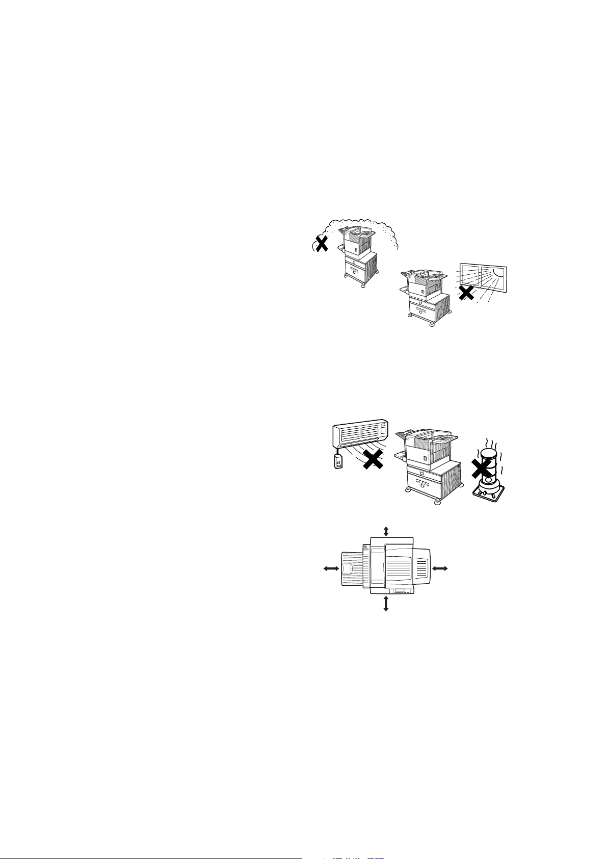
3. Do not install your machine in areas that are:
● damp, humid, or dusty
● exposed to direct sunlight
● poorly ventilated
● subject to extreme temperature
or humidity changes, e.g., near an air
conditioner or heater.
4. Be sure to allow the required space around
the machine for servicing and proper
30cm
ventilation.
80cm 60cm
60cm
A small amount of ozone is produced within the printer during operation. The emission level is
insufficient to cause any health hazard.
The present recommended long term exposure limit for ozone is 0.1 ppm (0.2 mg/m
3
) calculated as an
eight-hour time-weighted average concentration. However, since the small amount that is emitted may
have an objectionable odour, it is advisable to place the printer in a ventilated area.
Before you do anything please read this — 6
Page 8
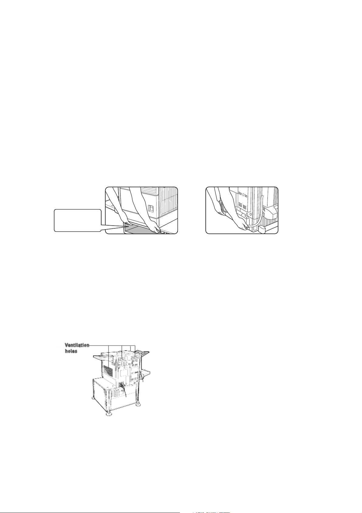
Moving the machine
Lift this machine at the positions shown in the illustration below and carry it horizontally.
>CAUTION
Two people are required to lift and carry this machine. The centre of gravity of the machine is slightly
to the left of the centre of the machine when viewed from the front. If a duplex module is installed the
centre of gravity will be even further shifted to the left. When lifting the machine be careful to steady it
to prevent it from toppling. Also be sure that all covers and the duplex module are securely closed and
latched before lifting.
If a duplex module is installed, do not lift the machine by the module as it may come off causing it and
the machine to drop.
Remove the multi-purpose drawer and lift at the positions shown in the illustration. To avoid injury be
sure to completely remove the multi-purpose drawer.
Front side Rear side
Remove the multi
purpose drawer
in advance.
If the machine has been placed on a stand/paper drawer:
The stand/paper drawer is equipped with casters for moving. Unlock the adjusters of the stand/paper
drawer and gently move the machine taking care to steady it to prevent it from toppling.
>CAUTION
The centre of gravity of this machine is a little deviated to the left from the centre. If the machine is not
equipped with a multi-purpose drawer or a stand/paper drawer, take care in opening the left side cover
(or the duplex module) not to cause toppling of the machine.
Do not cover the ventilating holes of this machine. Do not install this machine in a location where these
holes are covered. If these holes are covered, heat will not be dissipated and a fire may be caused.
7 — Before you do anything please read this
Page 9
GENERAL WARNINGS
1. Do not touch the photo drum. Scratches or smudges on the drum will cause dirty prints.
2. The fusing unit is extremely hot. Exercise care in this area.
3. Five adjusters are provided on all optional stand/paper drawer units.
These adjusters should be lowered until they contact the floor.
4. Do not make any modifications to this machine. Doing so may result in
personal injury or damage to the machine.
5. Since this machine is heavy, to prevent injury it is recommended that it
be moved by more than one person.
6. When connecting this machine to a computer, be sure to turn both computer and printer off
before connecting the devices.
7. Do not print anything which is prohibited from printing by law. The following items are normally
prohibited from printing by national law. Other items may be prohibited by local law.
>Money
>Stamps
> Bonds
>S
tock
Bank drafts and cheques
>
Passports
>
Drivers’ licenses
>
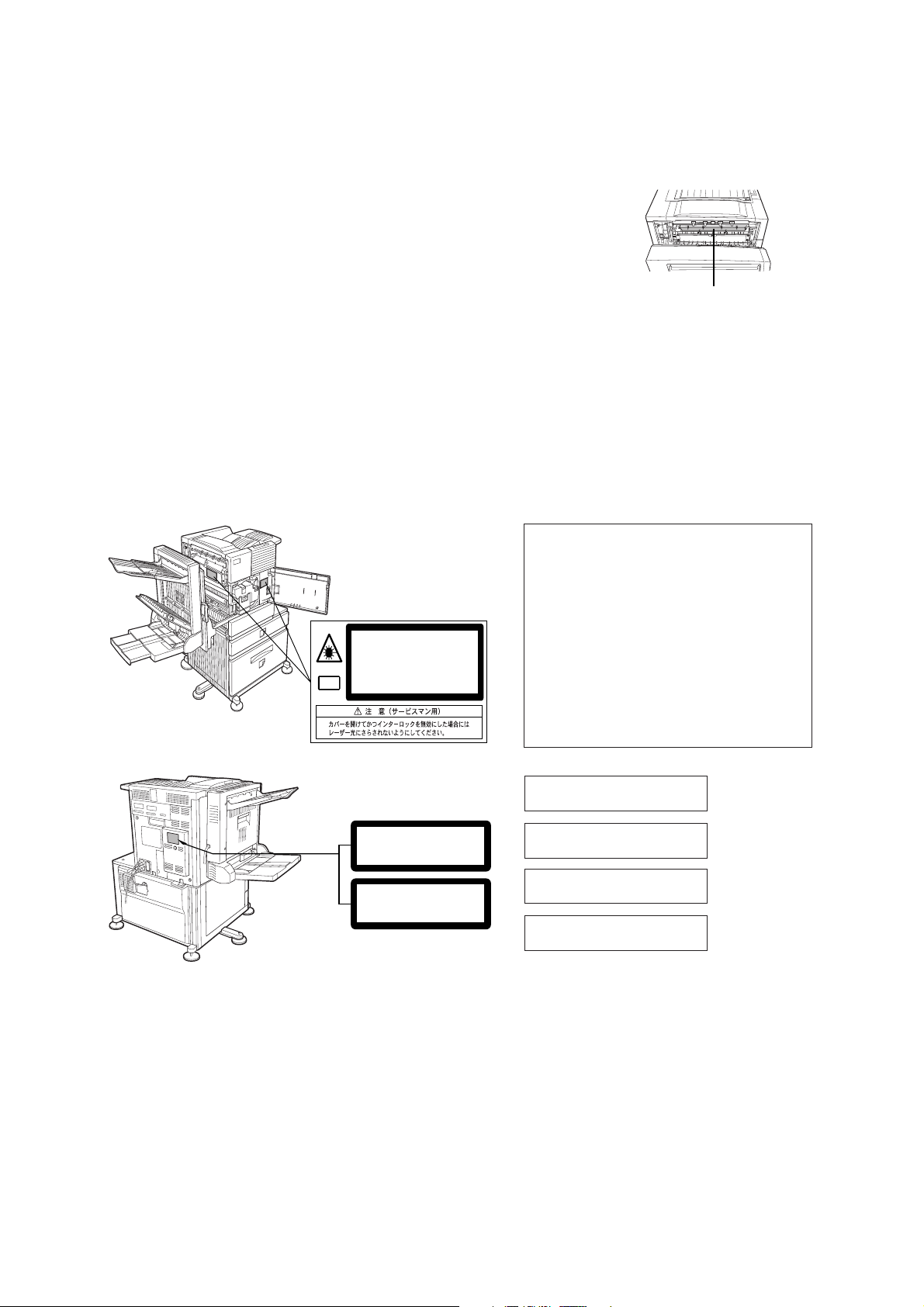
Fusing unit
CAUTION
VORSICHT
ADVARSEL
ADVERSEL
VARNING
Laserstrahl
AVATTAESSA JA SUOJALUKITUS OHITETTAESSA OLET ALTTIINA NÄKYMÄTÖNTÄ
LASERSÄTEILYLLE. ÄLÄ KATSO SÄTEESEEN.
VAR O!
LASER PRODUCT
LASER KLASSE 1
INVISIBLE LASER RADIATION WHEN OPEN AND INTERLOCKS DEFEATED.
AVOID EXPOSURE TO BEAM.
UNSICHTBARE LASERSTRAHLUNG WENN ABDECKUNG GEÖFFNET UND
SICHERHEITSVERRIEGELUNG ÜBERERÜCKT. NICHT DEM STRAHL AUSSETZEN.
USYNLIG LASERSTRÅLING VED ÅBNING, NÅR SIKKERHEDSAFBRYDERE ER
UDE AF FUNKTION. UNDGÅ UDSAETTELSE FOR STRÅLNING.
USYNLIG LASERSTRÅLING NÅR DEKSEL ÅPNES OG SIKKERHEDSLÅS BRYTES.
UNNGÅ EKSPONERING FOR STRÅLEN.
OSYNLIG LASERSTRÅLNING NÄR DENNA DEL ÄR ÖPPNAD OCH SPÄRRAR ÄR
URKOPPLADE. STRÅLEN ÄR FARLIG. BETRAKTA EJ STRÅLEN.
CLASS 1
CAUTION
INVISIBLE LASER RADIATION
WHEN OPEN INTERLOCKS
DEFEATED. AVOID EXPOSURE
TO BEAM.
VORSICHT
UNSICHTBARE
LASERSTRAHLUNG WENN
ABDECKUNG GEÖFFNET UND
SICHERHEITSVERRIEGELUNG
ÜBERBRÜCKT. NICHT DEM
STRAHL AUSSETZEN.
ADVARSEL
USYNLIG LASERSTRÅLNING
VED ÅBNING, NÅR
SIKKERHEDSBRYDERE ER
UDE AF FUNKTION. UNDGÅ
UDSAETTELSE FOR
STRÅLNING.
LAITTEEN KÄYTTÄMINEN
MUULLA KUIN TÄSSÄ
KÄYTTÖOHJEESSA
MAINITULLA TAVALLA SAATTAA
ALTISTAA KÄYTTÄJÄN
TURVALLISUUSLUOKAN 1
YLITTÄVÄLLE
NÄKYMÄTTÖMÄLLE
LASERSÄTEILYLLE.
OM APPARATEN ANVÄNDS PÅ
ANNAT SÄTT ÄN I DENNA
BRUKSANVISNING
SPECIFICERATS, KAN
ANVÄNDAREN UTSÄTTAS FÖR
OSYNLIG LASERSTRÅLNING,
SOM ÖVERSKRIDER GRÄNSEN
FÖR LASERKLASS 1.
CLASS 1 LASER PRODUCT
LASER KLASSE 1
LUOKAN 1 LASERLAITE
KLASS 1 LASERAPPARAT
VAROITUS!
VARNING
Do not throw toner or a toner cartridge into a fire. Toner may spill out or scatter, causing a burn.
8.
FOR NORTH AMERICA
SAFETY PRECAUTIONS
This Digital Equipment is rated Class 1 and complies with 21 CFR 1040.10 and 1040.11 of the CDRH
standards. This means that the equipment does not produce hazardous laser radiation.
For your safety, observe the precautions below.
> Do not remove the cabinet, operation panel or any other covers.
Gener al war nings — 8
Page 10

> The equipment’s exterior covers contain several safety interlock switches.
> Do not bypass any safety interlock by inserting wedges or other items into switch slots.
Use of controls or adjustments or performance of procedures other than those specified herein may result
in hazardous radiation exposure.
FCC Radio Frequency Interference Statement
This equipment has been tested and found to comply with the limits for a Class B digital device, pursuant
to Part 15 of the FCC rules. These limits are designed to provide reasonable protection against harmful
interference in a residential installation. This equipment generates, uses, and can radiate radio
frequency energy and, if not installed and used in accordance with the instructions, may cause harmful
interference to radio communication. However, there is no guarantee that interference will not occur in a
particular installation. If this equipment does cause harmful interference to radio or television reception,
which can be determined by turning the equipment off and on, the user is encouraged to try to correct the
interference by one or more of the following measures:
> Reorient or relocate the receiving antenna.
> Increase the separation between the equipment and receiver.
> Connect the equipment into an outlet on a circuit different from that to which the receiver is
connected.
> Consult the dealer or an experienced radio/TV technician for help.
FCC CAUTION: To assure continued compliance,(example- use only shielded interface cables when
connecting to computer or peripheral devices). Any changes or modifications not expressly approved by
the party responsible for compliance could void the user's authority to operate the equipment.
This device complies with Part 15 of the FCC Rules. Operation is subject to the following two conditions:
(1) This device may not cause harmful interference, and (2) this device must accept any interference
received, including interference that may cause undesired operation.
LASER CAUTIONS
This product contains a low power laser device. To ensure the user’s safety
do not remove any cover or attempt to gain access to the inside of the
product. Refer all servicing to qualified personnel.
Wave length 785 nm +10 nm /-15nm
Pulse times Europe 45 cpm model: (4.4 µs ± 4.4 ns)/7 mm
USA: 45 cpm model: (5.7 µs ± 5.7 ns)/7 mm
Output power 0.2 mW - 0.4 mW
9 — Laser cautions
Page 11

Laser cautions — 10
Page 12
OVERVIEW
Introduction
Thank you for buying the Oki B8300 high speed digital printer. Before attempting to use the product, it is
recommended that the user studies this manual to familiarise themselves with the main functions of the
product and to take notice of the various safety recommendations. A minimum level of computer literacy
is necessary for the installation of the printer drivers and Oki recommends that if the user is uncertain
how to proceed they should refer this item to their system adminstrator.
Original and paper sizes
The Oki B8300 uses media of standard sizes in both metric and imperial systems.The standard sizes
available are shown below.
Imperial Sizes AB system Sizes
TABLOID 11 X 17 A3 297 X 420
LEGAL 8½ X 14 B4 250 X 353
FOOLSCAP 8½
LETTER 8½ X 11 B5 176
EXECUTIVE 7¼ X 10½ A5 148 X 210
INVOICE 5½ X 8½
The meaning of “R” in original and paper size indications
X 13 A4 210 X 297
X 250
Some original and paper sizes can be placed in either portrait or landscape orientations.
To differentiate between the two sizes in the various tables further on in the book, the landscape
orientation size indication will contain an “R”. These are indicated as 8½
Sizes that can be placed only in the landscape orientation (11
x 17, 8½ x 14, 8½ x 13, A3, B4) do not
x 11R, 5½ x 8½R, A4R, B5R, etc.
contain the “R” in their size indication.
Landscape orientationPortrait orientation
Overview — 11
Page 13

Main Features
A wide range of accessories to enhance your productivity
Options, such as duplex units for producing two-sided output, additional paper feed units to increase the
variety of available paper sizes and paper capacity, paper output units to sort and otherwise organize
output.
600 dpi high resolution printing
High-definition and high quality printing with 600 dpi resolution can be performed.
Also high image quality, equivalent to 1200 dpi, can be obtained by using the smoothing function.
High speed monochrome printing
The printer achieves high speed printing at 45 A4 (or letter) size pages per minute.
PostScript compatible
PostScript 3 is standard.
Energy saving features
Preheat mode
The preheat mode is the first level of power reduction.The power is reduced to the fuser unit a preset time
after the machine has completed a job and no further machine operations have been made. The machine
can recover to the ready condition within a short period of time. The preset time to enter the mode can be
set by a key operator program.
Auto power shut-off mode
The auto power shut-off mode is the second level of power reduction. In this mode power is shut off to the
fusing unit and the touch panel. In this state more energy is saved than in the preheat mode but the time
to recover to the ready condition will be longer. The preset time to enter this mode can be set by a key
operator program.
When in use, and either of the above modes is active, the mode will be deactivated automatically by an
incoming job and the machine will automatically warm up and start to print when it has reached the ready
temperature.
Overview — 12
Page 14
PART NAMES AND FUNCTIONS
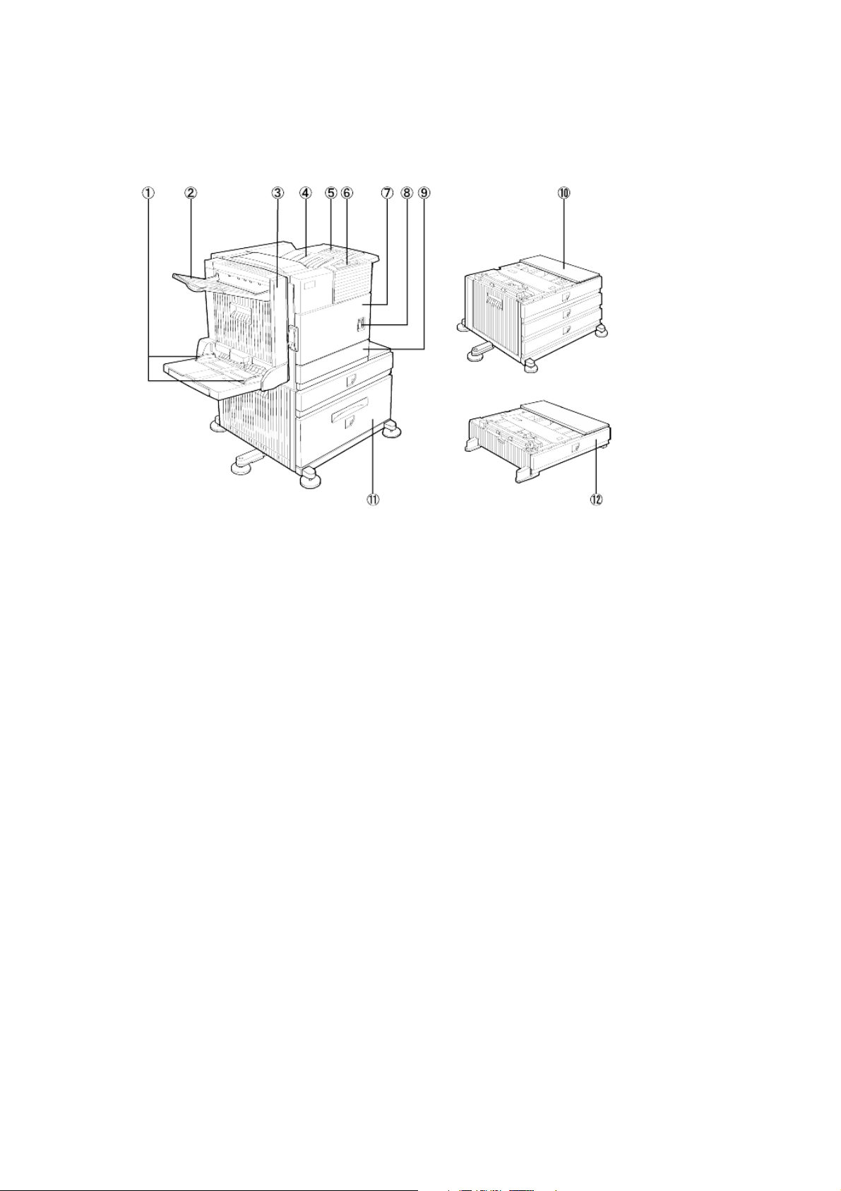
Exterior
1. Bypass tray paper guide
2. Exit tray
3. Duplex module/bypass tray
Module for two-sided printing.
4. Upper paper output area
Finished sheets are deposited here.
5. Upper exit tray extension
Provides support for large size paper.
6. Operation panel
7. Front cover
Open to add toner.
8. Main switch
Press to turn power on and off.
9. Paper tray 1
10. Stand/3 x 500 sheet paper drawer*
11. Stand/MPD and 2000 sheet paper drawer
12. Multi-purpose drawer*
Notes:
Items 2, 3, 10, 11 and 12 are peripheral
devices.
One of devices 10, 11 or 12 must be installed.
If you install device 3, 10 or 11 a power supply
unit must also be installed.
Overview — 13
Page 15
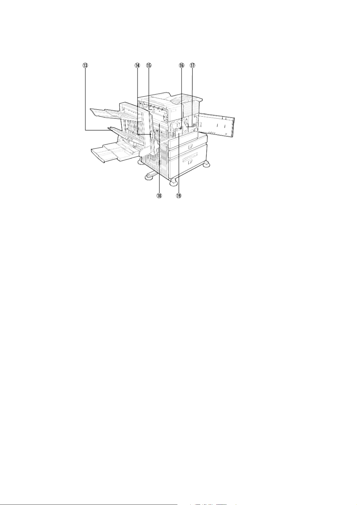
Interior
13. Duplex module side cover
Open when a misfeed has occurred in
the duplex module.
14. Side cover latch
Push up to open the side cover when
a misfeed has occurred in the main
unit.
15. Fusing unit
Lift up to open the side cover when a
misfeed has occurred in the main unit.
16. Developer cartridge
This cartridge contains developer
and must be removed and replaced
by a new cartridge when indicated on
the operation panel.
17. Toner cartridge (drum/toner cartridge)
The toner cartridge must be replaced
when indicated on the operation
panel.
18. Photoconductive drum
Images are formed on the photo drum.
19. Cartridge lock lever
When replacing the drum, toner or
developer cartridge, move this lever
down and pull it out.
For replacement and installation of
cartridges, refer to the relevant
documentation.
Your attention is drawn to the following
cautions
Take care when handling toner. Avoid getting
toner on your skin, in your eyes or on your
clothes. Should you get toner on you wash the
affected part with copious amounts of COLD
water. If ingested or you get toner in the eyes,
seek medical advice. If your clothes are
splattered, brush off as much of the toner as
possible and rinse with cold water.
The fusing unit is hot. Take care when removing
misfed paper.
Do not touch or damage the photo drum.
Overview — 14
Page 16
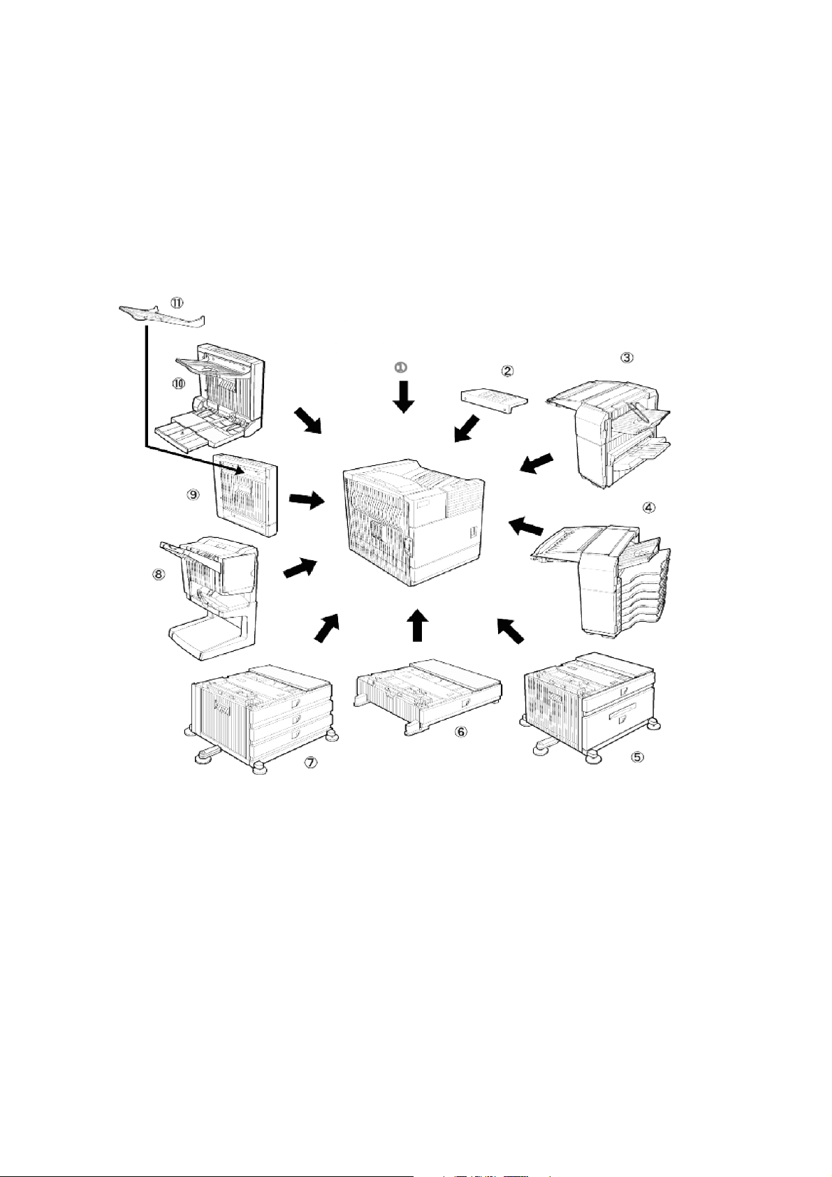
PART NAMES AND FUNCTIONS
Peripheral devices
included
Overview — 15
Page 17

1. Printer
2. Upper exit tray extension
Mount this unit to the upper paper
exit tray. This extension is needed to
support large size paper.
3. Finisher (B83F)
Output sheets can either be sorted in
page order or grouped by page.
Sorted sets or groups are offset
stacked for easy separation when
removed. Sorted sets can be
delivered either stapled or
unstapled.
4. Mail-bin stacker (B83MB)
This unit is an output sorter that has
seven receiving bins. The bin to
receive printed output can be
selected in the printer driver. Each
bin can be assigned to receive
printed output by an individual
person or by groups of people so
that their prints are separated from
other users making them easy to
retrieve.
When this unit is installed, any
copies will be sent to the top tray
and not to the mail bins.
can hold a maximum of 2000 sheets
of 80 g/m
2
(20 lb) paper.
6. Multi-purpose drawer (B83MP)
Up to 500 sheets of 80 g/m
2
paper can be loaded. Special papers
such as envelopes (standard sizes
only) and postcards can also be set.
7. Stand/3 x 500 sheet paper drawer
(B83TT)
This paper feed unit contains an
upper multi-purpose drawer (see
item 6) and two lower drawers each
of which can hold a maximum of 500
sheets of 80 g/m
2
(20 lb) paper.
8. Saddle stitch finisher (B83SS)
The saddle stitch finisher can
automatically place two staples for
centreline binding of prints or copies
and fold them along the centreline.
An optional hole punching unit is
available for installation into the
finisher.
9. Duplex module (B83D)
An optional duplex module must be
installed for automatic two-sided
printing.
(20 lb)
5. Stand/MPD and 2000 sheet paper
drawer (B83LT)
This paper feed unit contains an
upper multi-purpose drawer (see
item 6 ) and a lower drawer which
10. Duplex module/bypass tray (B83DB)
This module is basically the same as
above with the addition of a manual
bypass paper feed unit.
11. Mounted to the paper output port of a
duplex module.
Some peripheral devices cannot be installed together while others may require the installation of
one or more others to be functional.
See Chapter 6, List Of Combination Of Peripheral Devices.
Other optional equipment (not shown)
120 or 240V power supply unit (B83PS).
The voltage will depend upon the region in which the product is used.
Some peripheral devices require the installation of this power supply.
Hard disk drive (B83HD).
Extends the printer’s image storing capacity.
This unit is required for the job retention function to operate.
2-hole punch (B83THP).
2-3 hole punch (B83USP).
4-hole punch (B83FHP).
4-hole broad-space punch (B83FBP).
Overview — 16
Page 18
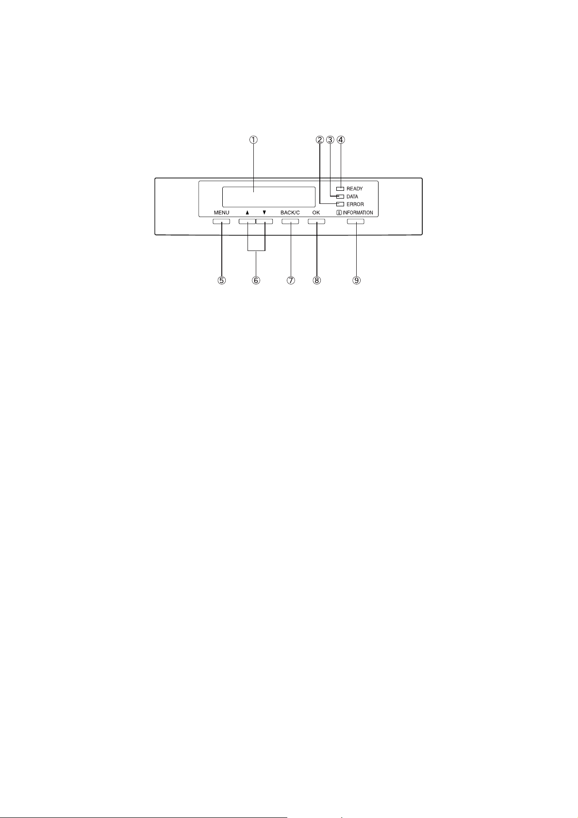
Operation panel of the main unit
The display and indicators show the current status of the printer. All printer settings are made by using
the keys and display panel.
1. Message display
Displays the current status of the printer. [ i ] displayed in any message indicates that the
[INFORMATION] key should be pressed.
2. [ERROR] indicator
Lights up when paper or toner must be added or when a misfeed has occurred in the machine.
Blinks when an abnormal condition has occurred in the machine.
3. [DATA] indicator
Lights up or blinks when print data is being received or output. Also lights up when job data is
stored by the job retention function.
4. [READY] indicator
Print data can be received when this indicator is lit.
5. [MENU] key
Press to select a menu group such as printer configuration menu, custom settings or execution of
print jobs held by the retention function. Also, press to return to the job status screen from the
setting screen of each job status group.
6. [ S/T] keys
Press to select menu or function items or to set numerical values for those items.
7. [BACK/C] key
Use this key to return to the previous screen in each menu selection, to cancel and delete the
current job or to delete a reserved job that has been selected.
8. [OK] key
Press to register the selected menu or function.
9. [INFORMATION] key
When [ i ] is displayed with a message indicating a paper misfeed, the relevant operation procedure
can be displayed by pressing the [INFORMATION] key. If the [INFORMATION] key or the [BACK/C] key
is pressed while the operation procedure is displayed, the information mode will be cancelled. If
this key is pressed and held down while printing is being performed or in standby mode, the total
number of printed pges and quantity of toner remaining (as a percentage) will be displayed.
17 — Overview
Page 19
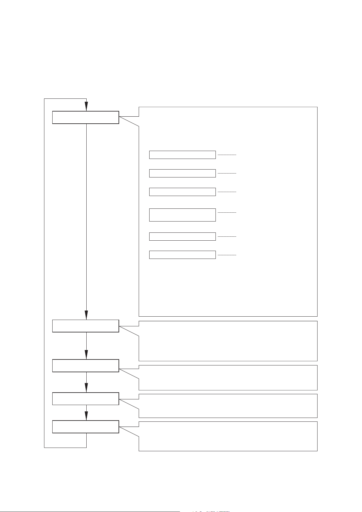
Menu group and Key explanations main unit operation panel
The menu groups are classified into five groups and are selected consecutively by pressing the [MENU]
key. If the [OK] key is pressed when the desired menu screen is displayed, a message will appear to
indicate the next required operation.
READY.
[MENU] key
Job status screen
The message [WARMING UP] will be displayed when the power is turned on and a
list of the current job plus reserved jobs or a list of completed jobs will be
displayed on the job status screen.
Examples of the various messages which will be displayed are shown below.
(Display example)
WARMING UP.
READY.
FROM TRAY #
CHANGE THE TONER
CARTRIDGE.
PAPER JAM.
ADD PAPER.*
[ADD PAPER]
*
When the status display shows [ADD PAPER], paper is required to
complete a job in progress. In this case, printing of the job will be
suspended until the required paper is added or another paper is
selected,see Setting the Paper Size and Type.
While a current job is suspended, the printer will print a reserved job if
paper is available from another source for that job but will not print
any other jobs.
The printer is warming up.
The printer is ready to print.
The printer is currently printing.
Out of toner.
Replace the toner cartridge.
See the relevant user manual.
A misfeed has occurred.
Out of paper. Load paper.
PRINT JOBS ON HOLD
[MENU] key
SET OPERATIONS
CONDITIONS
[MENU] key
CUSTOM SETTINGS
[MENU] key
KEY OPERATOR
PROGRAMS
[MENU] key
Print hold
If the job retention function is used from your computer, print data will be
stored in the printer as a hold job.
The job retention function can be used only if the printer is equipped
with a hard disk drive unit.
Condition settings
The printer condition settings are used for basic printer settings.
Custom settings
Custom settings are used to make settings based on use patterns.
Key operator programs
These are settings used by key operators (administrators of this product).
Overview — 18
Page 20

Cancelling a print job and deleting print data
1. Press the [BACK/C] key during printing.
Printing will stop and a message asking for confirmation to delete the job will appear.
2. Press the [OK] key to delete the data.
To cancel deletion, press the [BACK/C] key.
Printing will resume.
To delete print data of a reserved job (jobs stored in the printer)
Print data transmitted from computers will be stored in this printer (up to 99 jobs) and will be printed
sequentially.
To delete print data of a reserved job before starting printing:
1. Press the S or T key to display the desired data in the message display.
If you press the [BACK/C] key at this time, a confirmation message for deletion will appear.
2. Press the [OK] key to delete the data.
To cancel deletion, press the [BACK/C] key to cancel deletion,.
Printing will resume.
19 — Overview
Page 21
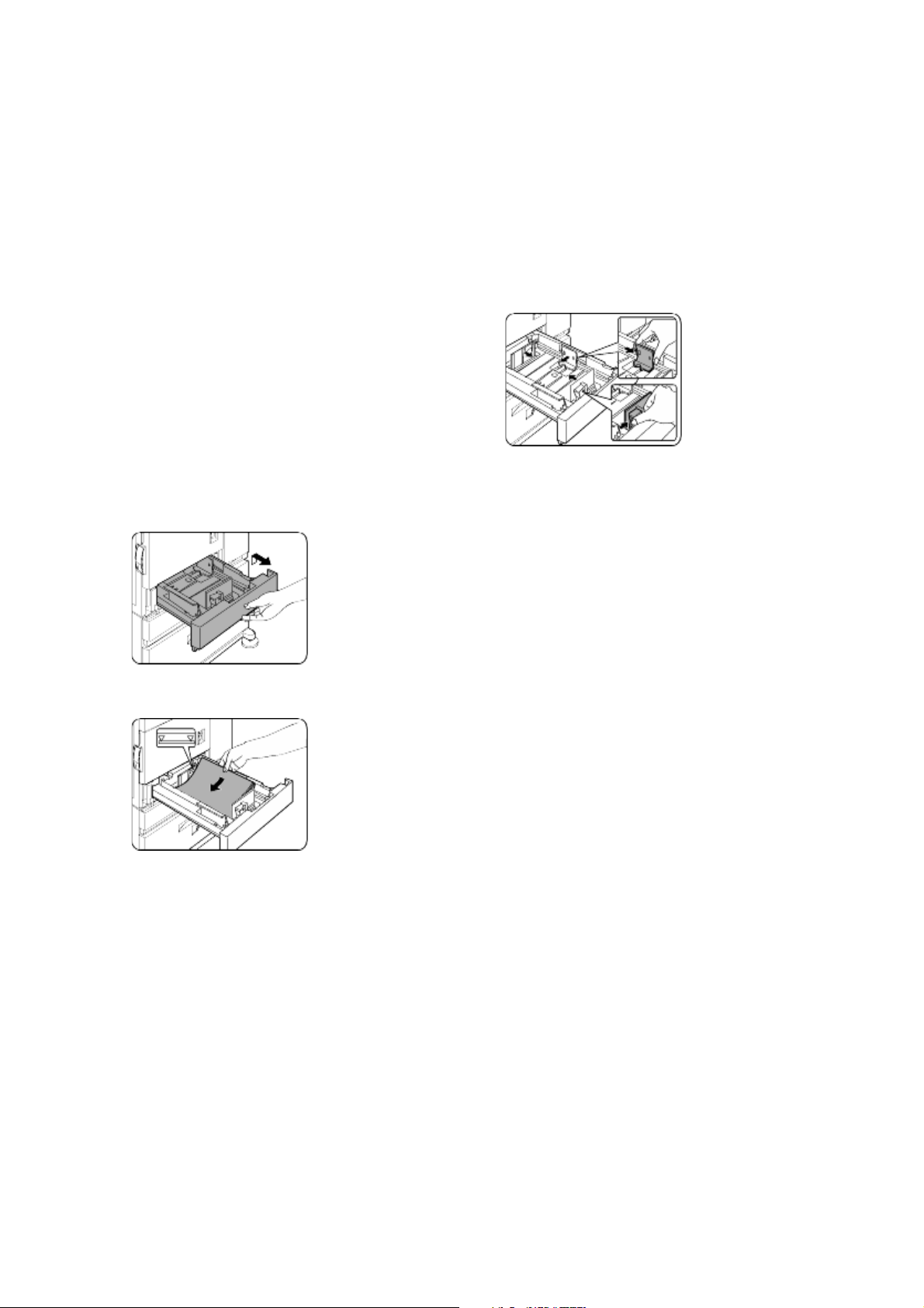
Loading Paper
Changing the paper size in paper tray 1
> The message “ADD PAPER” or “OPEN TRAY
AND ADD PAPER” will appear when paper
runs out during operation. Follow the
procedure below to load paper.
> Do not use curled or folded paper. Doing
so may cause a misfeed.
> For best results use a good quality paper
designed for use in page printers.
> When you change the paper type and size
in paper tray 1, set the paper type and
size referring to Setting the Paper Size
and Type.
> Do not place heavy objects into, or
press down hard upon, any tray which is
pulled out.
Loading paper in paper tray 1
1. Gently pull out tray 1 until it stops.
For paper tray 1, 8½" x 11", A4 or B5 size paper
can be set. Use the following procedure to
change the size as needed.
1. Pull out paper tray 1. If paper remains in
the tray, remove it.
2. Adjust the guide plates A and B in the tray
to the length and width of the paper.
The guide plates A and B can slide. Adjust them
to the paper size to be loaded while squeezing
their lock levers.
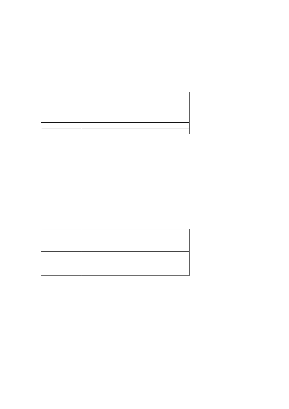
3. Load paper into the tray.
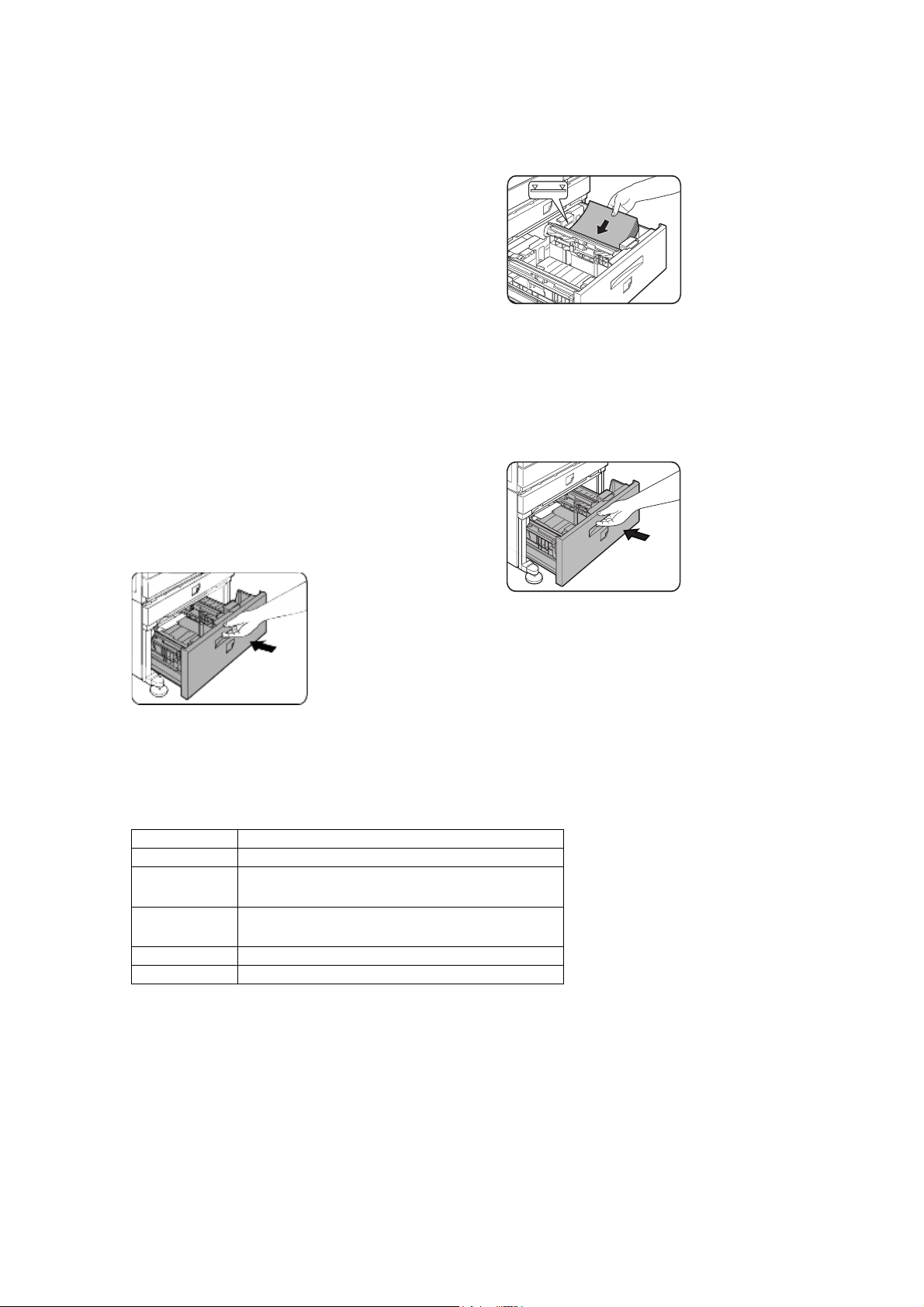
4. Gently push tray 1 firmly all the way into
the machine.
2. Load paper into the tray.
Do not load paper above the maximum height
line (approximately 500 sheets of 80 g/m
(20 lb) paper).
3. Gently push tray 1 firmly all the way into
the machine.
4. Set the paper type. If you change the
paper type, be sure to set the correct type
by referring to Setting the Paper Size and
Type section.
2
5. Set the paper size.
Be sure to set the paper size and paper type
referring to Setting the Paper Size and Type. If
this is not done, paper misfeeds will occur.
Changing paper size in paper tray 1 is now
complete.
Loading paper in paper tray 1 is now complete.
Overview — 20
Page 22
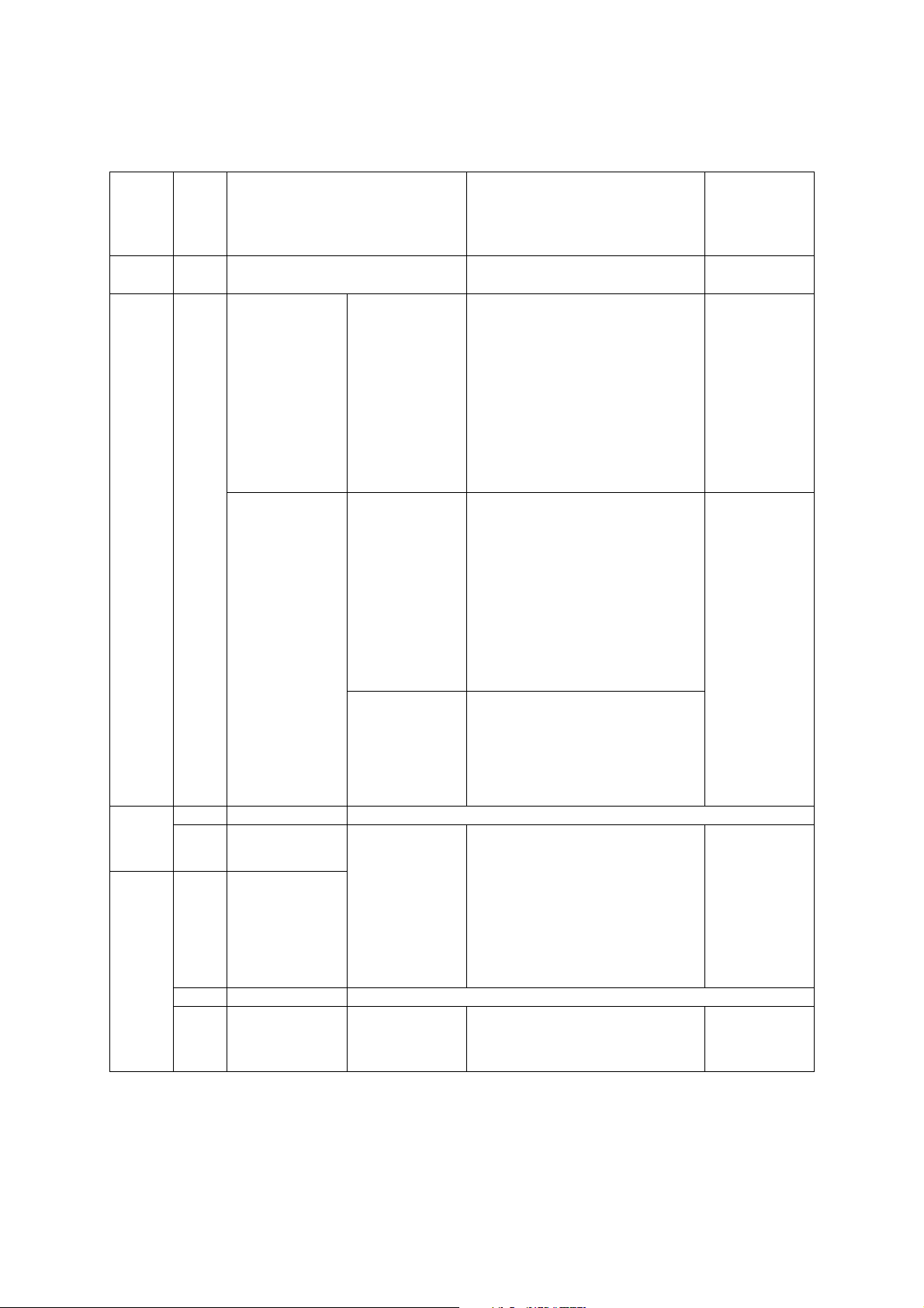
Specifications of paper trays
The specifications for types and sizes of paper for loading paper trays are shown below.
Tray Tray
Applicable paper types Applicable paper sizes Paper weight
No.
(tray
name)
Paper tray 1Tray 1 Plain paper. (Refer to the next page for
Multipurpose
drawer/
Tray 2/
bypass
tray
bypass
tray
Stand/3 x
500 sheet
Upper Tray 2 Same as multi-purpose drawer
Middle Tray 3 Plain paper. (Refer to
paper
drawer
Stand/
Lower Tray 4
MPD and
2000
sheet
paper
drawer
Upper Tray 2 Same as multi purpose drawer
Lower Tray 3 Plain paper. (Refer to
applicable plain papers.)
Plain paper. (Refer to
the next page for
applicable plain
papers.)
Special paper.
(Refer to the next
page for applicable
special papers.)
● Thick paper
● Labels
● Transparency film
Envelopes can only
be fed from the multipurpose drawer.
Applicable paper
stock weight for
envelopes is 75 to 90
2
g/m
or 20 to 23 lb
the next page for
applicable plain
papers.)
the next page for
applicable plain
papers.)
● 8½ x 11, A4, B5
● If [AUTO-INCH] is selected in setting the
paper size and type, the following paper
sizes can be used with the automatic
detection function: 11 x 17, 8½ x 14,
8½ x 11, 8½ x 11R, 7¼ x 10½R,
5½ x 8½R
● If [AUTO-AB] is selected in setting the
paper size and type, the following paper
sizes can be used with the automatic
detection function: A3, B4, A4, A4R, B5,
B5R, A5R, 8½ x 13
● Non-standard sizes
● If [AUTO-INCH] is selected in setting the
paper size and type, the following paper
sizes can be used with the automatic
detection function: 11 x 17, 8½ x 14,
8½ x 11, 8½ x 11R, 7¼ x 10½R,
5½ x 8½R
● If [AUTO-AB] is selected in setting the
paper size and type, the following paper
sizes can be used with the automatic
detection function: A4, A4R, B5, B5R
● Non-standard sizes smaller than A4 or
8½ x 11
● Applicable standard size envelopes:
COM-10, Monarch, DL, C5, ISO B5
● Non-standard size
●
If [AUTO-INCH] is selected in setting the
paper size and type, the following paper
sizes can be used with the automatic
detection function: 11 x 17, 8½ x 14,
8½ x 11, 8½ x 11R, 7¼ x 10½R, 5½ x 8½R
● If [AUTO-AB] is selected in setting the
paper size and type, the following paper
sizes can be used with the automatic
detection function: A3, B4, A4, A4R, B5,
B5R, A5R, 8½ x 13
● A4, 8½ x 11
60 to 105 g/m
2
or 16 to 28 lb
60 to 128 g/m
2
or
6 to 34 lb
See the remarks for
special paper on
the next page
● 60 to 105 g/m
2
or 16 to 28 lb
● 60 to 105 g/m
2
or 16 to 28 lb
21 — Overview
Page 23
Applicable plain paper
For satisfactory results, plain paper must conform to the following requirements.
Paper in AB system Paper in inch system
A5 to A3 5½ x 8½ to 11 x 17
Plain paper
60 to 105 g/m
Recycled, coloured, pre-punched, pre-printed and letterhead papers must conform to the same conditions as above.
2
or 16 to 28 lb
Applicable special paper
For satisfactory results, special paper must conform to the following requirements.
Type Remarks
Special paperr Thick paper ● For A5 to A4, 5½ x 8½ and 8½ x11
Transparency film, labels
Envelopes
sizes, thick paper ranging from 60 to 128
2
g/m
or16 to 34 lb or can be used
●
For sizes larger than A4 or 8½ x 11,
thick paper ranging from 60 to 105g/m
or 16 to 28 lb can be used
● Other thick papers
● Index stock (176 g/m
2
or 65 lb) can
be used
● Cover stock (200 to 205 g/m
2
or
110 lb) can be used but only for A4,
8½ x 11, paper in portrait orientation
● For A5 or 5½ x 8½ paper, orientation
must be landscape
● Use media from established suppliers
(Avery, 3M, etc.) which are described
as being suitable for digital printers
● Failing to do so may leave adhesive
residue in the printer, causing paper
misfeeds, smudges on prints or other
problems
● Applicable standard envelopes:
COM-10, Monarch, DL, C5, ISO B5
● Envelopes can only be fed from the
multi-purpose drawer
● Applicable paper stock weight for
envelopes is 75 to 90g/m
2
or
20 to 23 lb
2
Overview — 22
Page 24
Setting the paper size and type from the operation panel on the main printer
When the paper size or type is changed in a
paper tray, set them up by referring to the
following procedure.
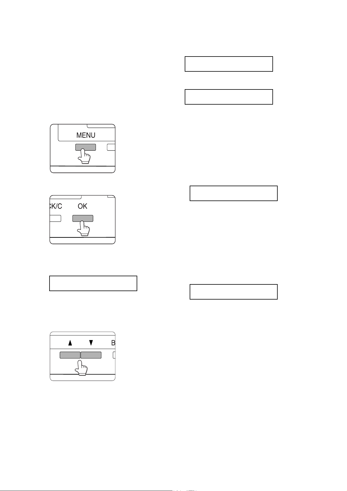
1. Press the [MENU] key repeatedly until
CUSTOM SETTINGS appears in the
message display.
2. Press the [OK] key.
If TRAY 1 is selected in step 4, the message
shown below will appear in the display.
LETTER
PLAIN
6. Press the T key
CHANGE TRAY
SETTING OK
If TRAY 1 is selected in step 4, the message
shown above will appear in the display.
7. Press the [OK] key. To cancel the setting
change, press the [BACK/C] key to return
to step 4.
8. Select the paper type that has been set in
the tray. Press the S or T key repeatedly
until the paper type that has been set
appears.
PLAIN
OK
3. When the [OK] key is pressed, TRAY
SETTING will appear in the message
display.
TRAY SETTING
TRAY 1
When the [OK] key is pressed, the message
shown above will appear in the message
display.
4. Select the desired paper tray.
T
> Special paper such as thick paper,
transparency film, labels, and postcards
can be set for tray 2 and the bypass tray.
> Envelopes can be set only for tray 2.
9. Press the [OK] key.
10. Ensure that the desired paper size is
selected. Press the S or T key
repeatedly until the desired paper size
appears.
PLAIN
OK
> Depending on the selected tray, a
selection for AUTO-AB and AUTO-INCH
may appear. AUTO-AB: Select when you
have set AB system paper.
> AUTO-INCH: Select when you have set
inch system paper.
> When the paper system is changed from
the inch system to the AB system or vice
versa, the paper type must be designated.
Select the paper type.
Press the S or T key repeatedly until the
desired paper tray is indicated in the display.
5. Press the [OK] key.
The paper size and paper type of the tray
selected in step 4 will appear.
> If you have set paper of non-standard
size, select NON STANDARD. This size can
be selected when tray 2 or the bypass tray
has been selected in step 4.
11. Press the [OK] key to complete the
setting.
Overview — 23
Page 25
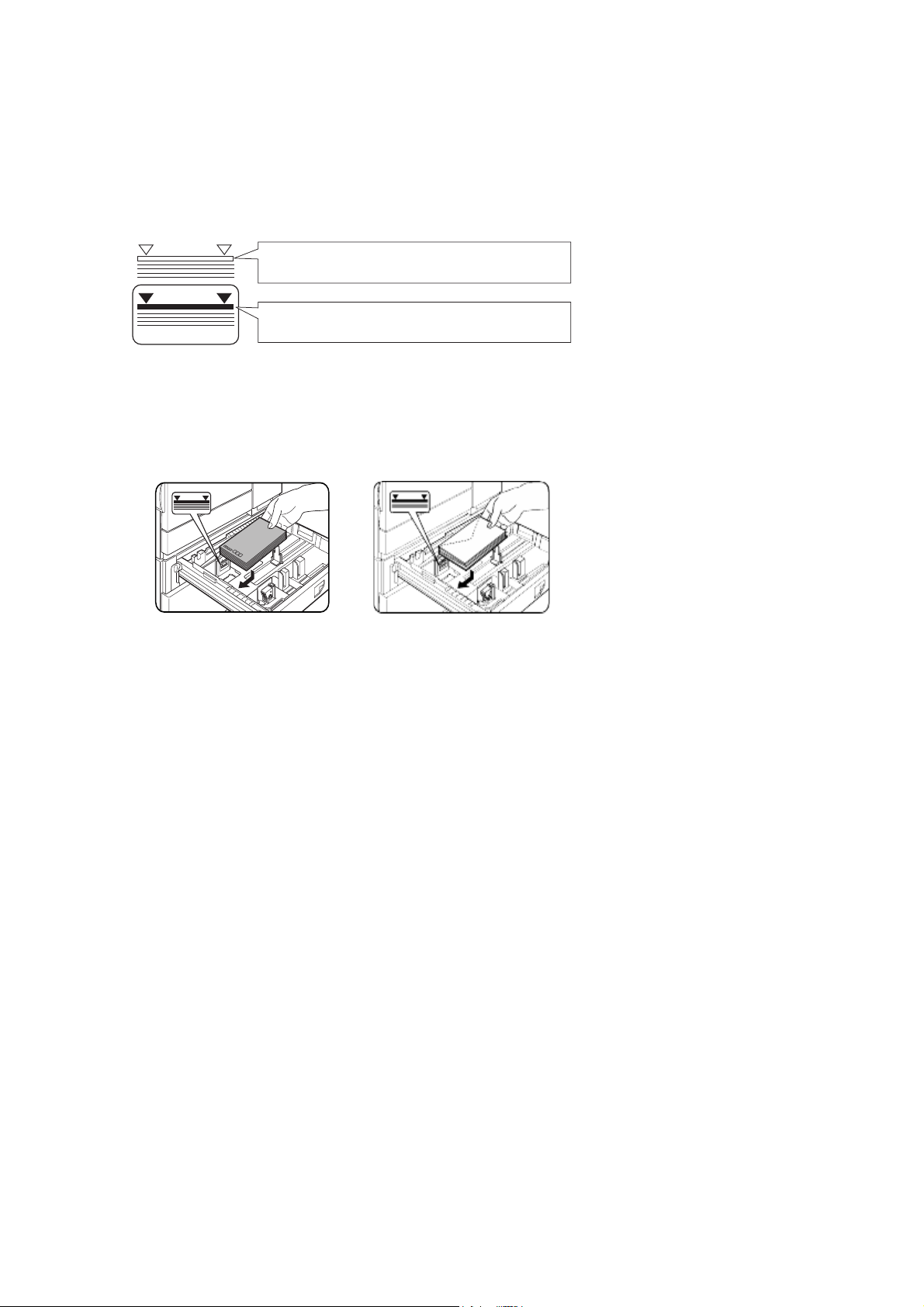
Loading paper in the multi-purpose drawer
The method of loading paper into the multi-purpose drawer is the same as for paper tray 1 as previously
described. When loading envelopes, postcards or transparency film, follow the descriptions below.
> Two maximum height lines are indicated: one for plain paper and one for special paper.
Maximum height line for plain paper
Do not exceed this line when loading plain paper.
Maximum height line for special paper (red line)
Do not exceed this line when loading special paper.
Setting envelopes or postcards
When setting envelopes or postcards in the multi-purpose drawer, set themas shown below.
Loading postcards Loading envelopes
Load postcards print side up
to the rear left of the tray as
shown.
Envelopes can only be
printed on the address side.
Be sure to place envelopes
with the address side up and
the top of the envelope to the
rear.
Printing on to envelopes or postcards
> Attempting to print on to both sides of envelopes or postcards may result in misfeeds or poor prints.
> Do not use pre-printed envelopes.
> To avoid wrinkling, misfeeds or poor printing, make sure the postcard stock is not curled.
Printing on to envelopes
> Do not use envelopes that have metal clasps, plastic snaps, string closures, windows, linings, self-
adhesive patches or synthetic materials. Attempting to print on these may cause misfeeds,
inadequate toner adherence or other problems.
> Enbossed envelopes whose surface is not flat may cause the smudged prints.
> Under high humidity and temperature conditions the glue flaps on some envelopes may become
sticky and be sealed closed when printed.
> Use only envelopes which are flat and crisply folded. Curled or poorly formed envelopes may be
poorly printed or may cause misfeeds.
Overview — 24
Page 26
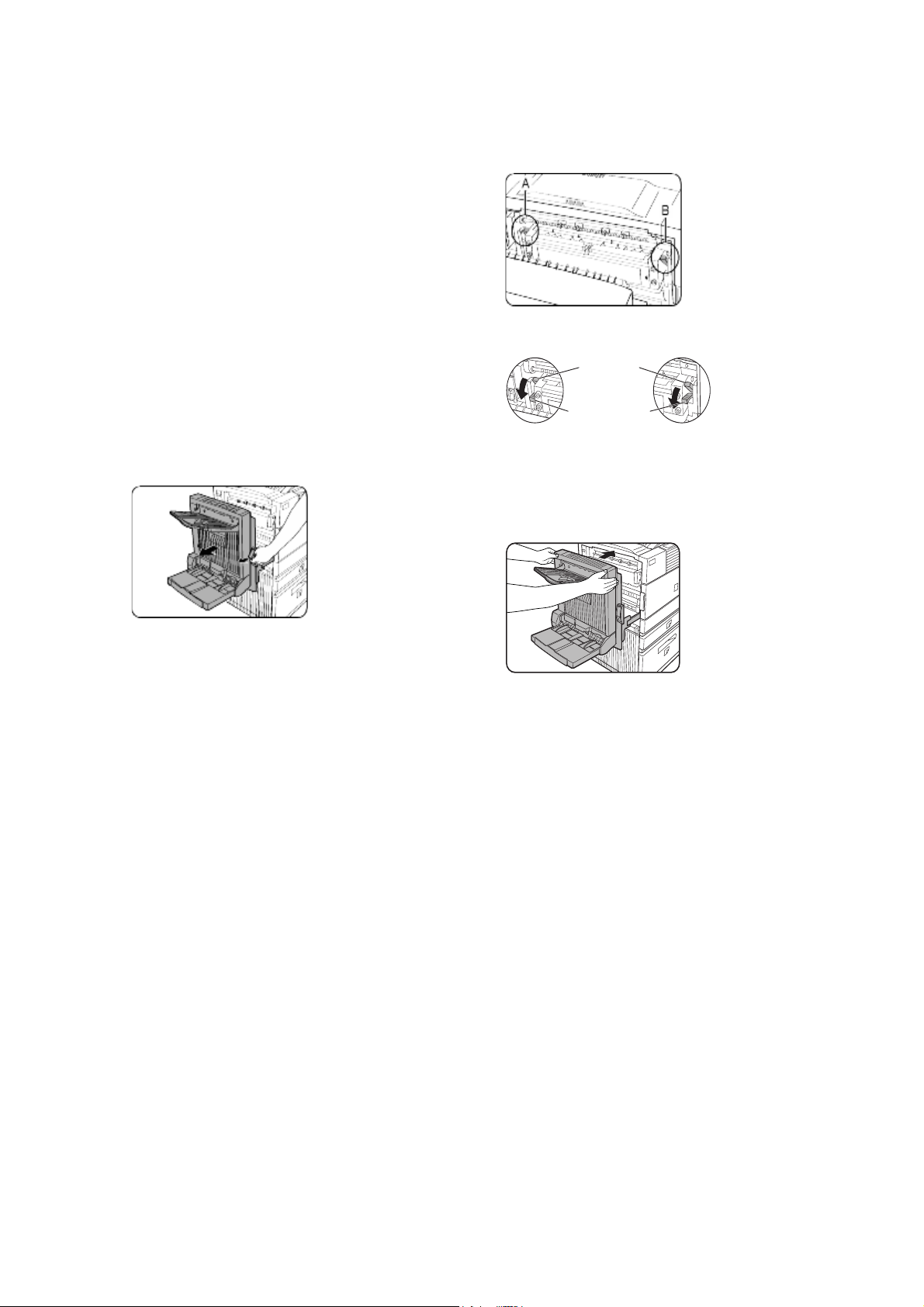
Fusing unit pressure adjusting levers
When feeding envelopes from the multipurpose drawer, damage to the envelopes or
smudges on prints may occur even if envelopes
within specification are used. In this case, the
problem may be reduced by shifting the fusing
unit pressure adjusting levers from the normal
position to the lower pressure position. Follow
the procedure below.
Be sure to return the lever to the normal
position when finished feeding envelopes. If
not, inadequate toner adherence, paper
misfeeds or other problems may occur.
2. Lower the two fusing unit pressure
adjusting levers marked A and B in the
illustration.
Normal position
1. Unlatch the duplex module and slide it to
the left. If the machine is not equipped
with a duplex module, open the side cover
to gain access.
Lower pressure position
Rear side of
A:
fusing unit
Front side of
B:
fusing unit
3. Gently close the duplex module. If the
machine is not equipped with a duplex
module, close the side cover.
Overview — 25
Page 27
Loading transparency film
Be sure to load the transparency film with the white label side up.
Make sure no image will be printed on the label.
Printing on the label may cause smudges on prints.
Transparency film must be placed in portrait orientation.
Specifications (multi-purpose drawer)
Name Multi-purpose drawer
Paper size/weight See specifications of paper trays
Paper capacity
Dimensions 654 mm (W)
Weight Approx. 11 kg (24.3 lb)
500 sheets 80g/m
25¾" (W)
Specifications are subject to change without notice.
2
(20 lb) of paper, 40 envelopes, 20 postcards
x 567 mm (D) x 144 mm (H)
21
x 22
/64" (D) x 543/64") (H)
Loading paper in the stand/3 x 500 sheet paper drawer
● Upper paper tray
The upper tray is the same as the multi-purpose drawer. Use the upper tray according to the instructions
for the multi-purpose drawer.
● Middle and lower paper trays
Up to 500 sheets of recommended plain paper can be loaded into these trays. The method of loading
paper is the same as for paper tray 1 in the main unit.
If the paper size or paper type is changed in either paper tray, the tray settings must be changed in
custom settings. Refer to Setting the Paper Size and Type.
Specifications (stand/3 x 500 sheet paper drawer)
Name Stand 3/500 sheet paper drawer
Paper size/weight See specifications of paper trays
Paper capacity
(ordinary paper)
Dimensions 619 mm (W) x 664 mm (D) x 404 mm (H)
Weight Approx. 32 kg (70.6 lb)
500 sheets 80g/m
3
24
/8" (W) x 265/32" (D) x 1529/32") (H)
Specifications are subject to change without notice.
2
(20 lb) each
Overview — 26
Page 28
Loading paper in the stand/MPD and 2000 sheet paper drawer
● Upper paper tray
The upper paper tray is equivalent to the multipurpose drawer. The method of loading paper
and the paper that can be used are the same as
for the multi-purpose drawer. Refer to the
description of the multi-purpose drawer.
2. Load paper into the right-hand paper
feed tables. This holds approximately
1,200 sheets.
● Lower paper tray
The lower paper tray is a large capacity tray that
holds 2,000 sheets of A4 or 8½" x 11" paper
(80 g/m
2
or 20 lb). Use the following procedure
to load paper into the large capacity tray.
If the paper size or paper type is changed in
either paper tray, the tray settings must be
changed in custom settings. Refer to Setting
the Paper Size and Type.
1. Pull out the large capacity tray until it
stops.
3. Raise the paper guide and load paper into
the left-hand paper feed table. This holds
approximately 800 sheets. After loading
paper, be sure to return the paper guide.
4. Gently push the large capacity paper tray
firmly all the way into the printer.
5. Set the paper type.
If you have changed the paper size from
the AB system to the inch system or vice
versa, select the relevant type referring to
Setting the Paper Size and Type.
Loading paper in the stand/MPD and
2000 sheet paper drawer is now
complete.
Specifications (stand/MPD and 2000 sheet paper drawer)
Name Stand/MPD and 2000 sheet paper drawer
Paper size/weight See specifications of paper trays
Paper capacity
(ordinary paper)
Dimensions 619 mm (W) x 664 mm (D) x 404 mm (H)
Weight Approx. 34 kg (75 lb)
Upper tray: 500 sheets 80g/m
Lower tray: 2,000 sheets 80g/m
3
/8" (W) x 265/32" (D) x 1529/32") (H)
24
Specifications are subject to change without notice.
2
(20 lb)
2
(20 lb)
Overview — 27
Page 29

Storage of supplies
Oki recommends the use of Oki original consumables. Counterfeit products may damage your printer's
performance and invalidate your warranty.
Standard supplies for this product that are to be replaced by the user include:
Paper, print cartridge, developer cartridge, and staple cartridge for the finisher.
● Proper storage
Store the supplies in a location that is
> Clean and dry.
> At a stable temperature.
> Not exposed to direct sunlight.
● Store paper in the wrapper and lying flat.
> Paper incorrectly stored, or out of the wrapper, may curl or become damp, resulting in misfeeds.
Supply list
Product European part no. North American part no.
27k Printer cartridge TONER-B8300 56115001
100k Developer cartridge DVLPR-B8300 57100101
Staple Pack for Finisher STAPLE-B8300-FNR 57100201
Staple Pack for Saddle Stitcher STAPLE-B8300-SSF 57100801
> If a cartridge is to be discarded, dispose of it according to local requirements.
> Store printer and developer cartridges out of the reach of children.
Overview — 28
Page 30

Adding toner
When toner runs out, the message CHANGE
THE TONER CARTRIDGE will appear on the
display indicating that the print cartridge must
be replaced. If you press and hold down the
[INFORMATION] key while printing is being
performed or in standby, the quantity of toner
remaining (as a percentage) will be displayed.
When the percentage appears within the range
of 0-25 per cent prepare a new printer
cartridge.
3. Pull out the duplex module. Unlatch the
unit and gently move the module away
from the machine. If the machine is not
equipped with the duplex module, open
the side cover to access.
The machine as shipped does not have a
cartridge installed. Follow the steps below for
instructions for installing the first cartridge
omitting step 4.
● The print cartridge contains toner
and a photoconductive drum. The
photoconductor on the drum can
deteriorate by exposure to light for
an extended period of time.
● Do not remove the cartridge from
its protective package until it is
ready to be installed into the
machine.
1. Turn off the power and open the front
cover.
4. While depressing the lock release button,
pull out the printer cartridge and remove it.
5. Remove the new printer cartridge from its
bag and remove the protective material A.
A
6. Shake the new cartridge horizontally five
or six times.
2. Lower the cartridge lock lever.
7. Insert the new printer cartridge. Push the
cartridge in until it locks securely into
place.
Overview — 29
Page 31

8. Gently remove the sealing tape from the
cartridge.
9. Remove the drum protective sheet from
the printer cartridge.
10. Close the duplex module. If the machine is
not equipped with the duplex module,
close the side cover.
11. Return the cartridge lock lever and close
the front cover.
> Do not touch or damage the surface of the
photo drum.
Photoconductive drum
● Do not shake the developer cartridge after the
sealing tape has been removed. If the cartridge
is shaken after the tape is removed, some
developer will come out of the cartridge.
Overview — 30
Page 32

Developer cartridge replacement
When the cartridge needs replacing, a message
indicating the need to replace it will appear in
the display. Follow the procedure below to
replace the developer cartridge. The machine
as shipped from the factory does not have a
cartridge installed.
Follow the procedure below to install the first
cartridge omitting steps 3 and 4.
1. Turn off the power and open the front
cover.
5. Remove the new developer cartridge from
its bag and remove the tape and
protective material A and B.
A
B
6. Shake the new developer cartridge
horizontally five or six times.
2. Lower the cartridge lock lever.
3. Remove the developer cartridge. Push the
lock release button and pull out the
developer cartridge until it stops.
4.
Push the lock button at the rear and
remove the developer cartridge.
7. Insert the new developer cartridge.
8. Push the cartridge in until it locks
securely into place.
9. Close the front cover. The machine will
become available in about two minutes.
Overview — 31
● Do not shake the developer cartridge after the
sealing tape has been removed. If the cartridge
is shaken after the tape is removed, some
developer will come out of the cartridge.
Page 33

Overview — 32
Page 34

PRINTING FROM A COMPUTER
This chapter describes how to install and how to use the printer drivers and printer utilities on a
computer. This chapter also describes the job retention function that allows a print start operation from
the operator panel of the printer.
Connecting this machine as a local printer
When using this machine as a local printer, connect your computer to the parallel interface connector as
shown in the illustration. The cable is not supplied with the printer. A shielded cable which conforms to
both the printer specifications and your computer specifications must be obtained. Consult your
computer manual for the computer connection requirements.
18
36 19
1
Parallel interface connector
The parallel interface of the printer conforms to IEEE-STD-1284-1993.
The connector type on the printer is
a 36-pin DDK 57LE-40360-730B (D29) female connector or equivalent. For the specifications of the parallel
interface connector on the computer, see your computer manual.
Software for Windows
When using this product in a Windows environment, you must install a printer driver in your computer
system. Use the CD-ROM supplied with this unit for the installation of the driver. This product can be
connected through a parallel interface connector as described above, or connected as a network printer
through a Network Interface Card (NIC)..
The following software for Windows is contained in the CD-ROM.
> Printer drivers
> Printer utilities
> Installer. This is software used for installing printer drivers and printer utilities.
If you use Plug and Play or the Add Printer Wizard to install the driver without using this program,
see appropriate instructions.
Printer drivers Printer utilities
PCL printer drivers
(PCL5e and PCL6)
PostScript printer driver
(PostScript 3) and
PPD files (PostScript Printer
Description files)
Printer Administration
Utility
PrintSuperVision
Printer drivers Printer driver software converts print data from any application into data understood by
the printer.
Printer utilities Printer Administration Utility provides setting and monitoring of printers on a computer
and is used by system administrators. See the Help file as necessary.
Printing from a computer — 33
Page 35

INSTALLING PRINTER
PLUG AND PLAY OR ADD
DRIVERS AND UTILITIES
The following software can be installed from
the installer supplied on the CD-ROM:
• PCL printer drivers (PCL5e and PCL6)
• Printer Administration Utility.
Execute installation from the CD-ROM using the
following procedure.
1. Start Windows.
2. Insert the supplied CD-ROM into a CD-
ROM drive of your computer.
If your computer is configured for auto
start on CD-ROM insertion,
the lLanguage Select] or [User Select]
screen described in step 5 will appear.
(Steps 3 and 4 are not needed.)
3. On the [Start] menu, click [Run].
4. Enter the CD-ROM drive and setup
command. Then click [OK].
Example: If the CD-ROM drive is
designated as Drive R:, enter
[R:\SETUP.EXE].
PRINTER WIZARD
Before installation
Before installing the printer drivers, check the
following items.
Ensure that your computer system meets the
following requirements.
Computer
IBM PC/AT or compatible computer
Hardware requirements of the operating
system must be satisfied.
Operating system
Windows 95
Windows 98
Windows 2000
Windows NT 4.0
Windows Me
Windows XP
When using Plug and Play or using the Add
Printer Wizard to install printer drivers, enter
the directory name indicated below
as a source directory.
5. Select the language which you want to use.
6. Select [Online Manuals, Driver
Installation or Network Utilities] and
choose the item you want to install.
> A restart of your computer may be needed
depending on the system. Click [Yes] to
restart the computer.
Uninstalling printer drivers and printer utilities
When uninstalling a printer driver that has
been installed from the [Add Printer] wizard,
right-click the printer to be deleted from
[Printers] in the Control Panel and select
[Delete]. When uninstalling utility software, use
[Add/Remove Programs] in [Control Panel]. Use
the Windows standard operation for each case.
Installing printer drivers and utilities — 34
Page 36

Example of installation of a printer driver using
the Add Printer Wizard under Windows 98.
The installation example is described
assuming that the printer is connected as a
local printer and that the CD-ROM drive is
designated as [Drive G]. The procedure may
differ depending on the system environment.
1. Start Windows 98.
2. Insert the supplied CD-ROM into the CD-
ROM drive. If your computer CD-ROM
drive is configured for auto start, the tool
selection will appear. Click [Cancel] to
close the screen.
3. On the [Start] menu, select [Settings]
and then [Printers]. The Printer window
will appear.
4. Double-click the [Add Printer] icon.
5. Click the [Next] button.
6. Check the [Local Printer] radio button and
then click the [Next] button.
7. Click the [Have Disk] button.
8. The [Install From Disk] dialogue box will
appear.
9. Enter the file path as follows:
G:\OkiB8300\Drivers\English\
w9598\pcl5e
G:\OkiB8300\Drivers\English\
w9598\pcl6
10. Click the [OK] button.
11. Select the printer model to be used and
click the [Next] button.
Follow the instructions displayed by the
[Add Printer Wizard].
Plug and play or Add Printer Wizard — 35
Page 37

SETTING DRIVERS USING WINDOWS
This section describes the method of changing the printer driver settings from your computer using
Windows. if no printer driver has been installed, use the supplied CD-ROM to install it referring to
Installing Printer Drivers And Printer Utilities.
● Windows 95/98/Me
Screens for Windows 98 are used in the
description below.
1. On the [Start] menu, select [Settings] and
then [Printers]. The Printer window will
appear.
2. Right-click the installed printer driver and
select [Properties]. This example is the
screen displayed by selecting B8300PCL.
3. 5ee Printer Driver Help for additional
information.
4. Click the [OK] button.
● Windows NT 4.0/2000
Screens for Windows NT 4.0 are used in the
description below.
1. On the [Start] menu, select [Settings] and
then [Printers]. The Printer window will
appear.
2. Right-click the installed printer driver and
select [Document Defaults]. This example
is the screen displayed by selecting
B8300PCL5e.
3. See Printer Driver Help for additional
information.
4. Click the [OK] button.
For the setting concerning optional peripheral devices such as the duplex module, finisher
x
and stand/3
500 sheet paper drawer, right-click the installed printer, select [Properties], and then open
the [Configuration] tab. If you click the [Get Tray Status] button in the [Detail] dialogue box of the [Paper]
tab, the current tray information (paper size, paper type, and quantity of paper remaining) will be displayed.
Setting drivers using Windows — 36
Page 38

PRINTER CONFIGURATION THROUGH A NETWORK
If you access the Web pages of this product
from your computer using a Web browser such
as Internet Explorer or Netscape Navigator
various settings can be adjusted through the
network.
The following products and computer system
requirements are needed for accessing the
Web pages of this product.
Print server card (network interface card)
Recommended Web browser
Microsoft Internet Explorer 4.0 or later
or equivalent
Netscape Navigator 4.0 or later
or equivalent.
2. Input the IP Address previously specified
for this product into the [Address] field of
the browser.
> The following characters cannot be used
when setting the pages in the Web server
located in this product. Input characters
are case-sensitive.
Characters that cannot be input:
< > ”
Examples of improper input:
<abc> <abc “abc” “abc abc”
Accessing Web pages and displaying Help
Use the following procedure to access the Web
pages.
If the [Help] button in the menu frame is
clicked, the Help screen describing the various
function settings that can be operated remotely
from the Web pages for this product through
the network will appear.
For the setting of each function, see the
detailed description.
1. Open the Web browser on your computer.
When the connection is completed, the Web
page information of this product will be
displayed.
3. Click the [Help] button in the menu frame.
The configuration settings are described
in detail.
4. Close [Help].
Click the button. The display will return to
the Web page information of this product.
Printer configuration through a network — 37
Page 39

WEB PAGE ITEMS AND FUNCTIONS
Access setup
Access restriction to the Web pages is
described below.
Network Card Setup
To allow configuring the print server card
(network interface card), a link to the network
card Web page for is provided.
Custom Directory Setup
User index names in the display list on the
operator panel are set.
Alerts Message Parameters Setup*
The parameters for the alert message address
information are registered here. The alert
message is transmitted when a problem such
as a supplies requirement (toner or paper) or
error(device failure or paper misfeed) occurs.
SNMP Trap Setup
The Admin password is the same as the Web
Page password for the network card.
Password Setup
Password access to the Web pages can be set.
Two types of passwords are configurable (user
and administrator) . The Admin password is the
same as the Web Page password for the
network card.
IP addresses, trap community, and authentic community are set here.
Confidential reception
Data to be printed is sent to the machine and
held until released for printing from the
operator panel.
Web page items and functions — 38
Page 40

JOB CONTROL
This section describes the operation procedure
required for this function. To use job control in
your print job, select [Properties] on the printer
driver screen, open the [Main] tab and click [Job
Control.] The job hold function can be used only
if your printer is equipped with the hard disk
drive option.
Job control operation
1. Normal print
can also delete the data without executing
printing.
4. Proof print
(In this mode, no input from the operator panel
of the printer is needed.)
The print setting in this mode is the basic print
operation. If no problem occurs with the printer
(such as paper misfeed or toner out), the print
start operation is completed on the computer
and printing will be executed on the printer.
2. Hold after print
This mode can prevent a high-volume misprint
when many sets must be printed. If printing is
executed in this mode, only one set will be
printed and the remaining sets will be held as a
hold job.
After checking the finished printout, including
print position on paper and stapling position,
you can start printing of the remaining sets
from the operator panel of the printer. You can
also delete the data without executing printing.
5. Password (5 digits)
Password
Password
If a password is set in the printer driver setting,
a password entry is needed to start printing of
a password protected job. This mode can
increase the security of hold jobs.
In this mode, print data will be held in the Hold
Job List even after printing is complete. Printing
can be executed again from the operator panel
of the printer if needed. Also, the data can be
deleted from the operator panel if it is not
necessary.
3. Hold before print
This mode can reduce the possibility of missing
printout. If printing is made in this mode from the
computer, print data will not be output
immediately and will be stored in the printer as
a held job until released from the operator panel.
A print start operation can be made on the
operator panel of the printer as needed. You
39 — Job control
● Hold After Print mode with password:
Password entry on the operator panel of the
printer is needed to allow additional printing
of held job.
● Hold Before Print mode with password:
Password entry on the operator panel of the
printer is needed to start printing.
● Proof Print mode with password:
Password entry on the operator panel of the
printer is needed to allow the printing of the
remaining sets after printing one set. The first
set is printed without password entry.
Page 41

Hold job list
If Print after hold, Print before hold or Proof
print operation is performed on the computer,
print data will be held as a hold job.
(Up to 100 jobs can be held.
If the main switch is turned off, the stored data
of all jobs in hold will be cleared.)
3. Select the desired data.
If the number of jobs exceeds 100, the job is
processed as follows. A Notice Page will
printed in all cases.
> If Hold After Print is executed:
Printing will be executed but the job will
not be held.
> If Hold Before Print is executed:
Printing will not be executed and the job
will not be held.
> If Proof Print is executed:
Printing of one set will be executed but
the job will not be held.
When the machine is being operated from the operator panel:
1. Press the [MENU] key.
Press the Sor Tkey on the operator panel
repeatedly until the desired print job is
displayed.
4. Press the [OK] key.
5. Enter the first digit of the password and
press the [OK] key. (This is needed only if
a password has been set.)
Be sure to enter the same number that has
been entered on the computer. If no password
has been set, operation of steps 5 and 6 is not
needed.
PIN
- - - - -
When you press the [OK] key to register the first
digit after entering it, using the Sor Tkey on
the operator panel, “
*” will appear and “-” at
the second digit will blink. If you press the
[BACK/C] key, you can correct the entered
number.
PRINTJOBS ON HOLD will appear in the
message display.
2. Press the [OK] key.
When the [OK] key is pressed, a user name and
a file name of the print data stored as a held job
will appear.
MIKE
WORD-1
> The password is entered one digit at a
time starting with the first digit.
The inactive digits are shown as “
-”.
6. Use the same procedure as step 5 to enter
the password from the second digit to the
fifth digit and then press the [OK] key.
7. Select execution of printing, cancellation
of printing or data retention after printing,
and then press the [OK] key.
Deletion or retention of data after printing can
be selected. Alternatively deletion of data
without printing can be selected. Press
the
S
or Tkey until the desired choice appears.
PRINT AND DELETE
DATA — OK? T
PRINT AND SAVE DATA
— OK? T
DELETE THE DATA OK? TData will be deleted
Data will be deleted after
printing.
Data will be held after
printing.
without printing.
If this item is selected, the operation will be
complete. Steps 8 and 9 are not needed.
Job control — 40
Page 42

8. Verify that the desired number of copies is
set.
COPIES
10 SET
Printing will start. If printing of another job is
being executed, however, your job will be
registered as a print job. Printing of the job will
start after preceding jobs are completed.
The number of copies can be changed by using
the or key on the operator panel.
9. Press the [OK] key.
10. Operation is now complete.
11. To continue operation, repeat steps 1 to 9.
Printer account control
If the key operator program Auditing Mode is set, the number of printed pages can be totalled for each
account. The accounts for auditing are accounts that have been established with a key operator program
for counting the number of pages from the printer.
When executing a print operation from the computer, you must enter an account number on the setting
screen of the printer driver.The account number entry screen will be displayed by clicking [Job Control] in
the [Main] tab of the printer driver.
When an invalid account number is entered or no account number is entered, if key operator program
[Cancel jobs of invalid accounts] has been set, printing will not be performed.To perform printing in any
case, disable the program [Cancel jobs of invalid accounts]. In this case, the number of printed pages will
be accumulated in [OTHERS].
The job control screen will always appear when a print operation is executed from the printer driver if the
[Auto Job Control Review] check box in the [Main] tab of the printer driver is set.
41 — Job control
Page 43

USING THE PRINTER WITH A MACINTOSH
To use the printer in a Mac environment, run the
installer program to copy the PPD (PostScript
Printer Description) files to your System Folder.
For other conditions such as CPU and RAM
capacity, the core requirements of the
operating system must be satisfied. Ensure
that LaserWriter 8 has been installed in the
Mac’s [System] folder. If not, install it from the
CD-ROM supplied with your computer.
> NOTE: If this printer is connected to the
computer via a cross-over cable, turn on
the Mac before turning on this printer. If
not, the printer cannot be recognised as a
network printer.
PPD files
The PPD files for Macintosh are the files which
a Mac refers to when using its LaserWriter
printer driver for printing.
OKI PPD Utility
The OKI PPD Utility is used to register account
numbers and passwords when the Auditing
Mode or the Job Retention Function With
Password is used.This utility is also used to
change the registered account numbers and
passwords.
Display fonts
The CD-ROM contains display fonts for the Mac.
Install these as required.
Installing the utilities
The screens in the Mac OS 9.0 environment are
used below as examples. The display varies
with the operating system and printer driver
versions.
1. Turn on the computer .
2. Insert the supplied Drivers and Manuals
CD-ROM into the CD-ROM drive. An icon
will appear on the desktop.
3. Close all other applications and doubleclick the icon on the desktop. The files
contained in the CD-ROM will be
displayed.
4. Double-click the [Installer] icon. The
installer screen will appear.
Display fonts
Minimum system requirements
Computer
Apple Macintosh series
Apple Power Macintosh series
Operating system
Mac OS 8.51 to 9.x
Printer driver
LaserWriter 8 version 8.4.1 or later.
5. Please see the Readme file on the
CD-ROM for the latest information on
installing the software.
6. Click [Install] to start the software
installation. Once the installer has
finished, restart your computer.
> When uninstalling the PPD files from your
computer, select [Custom Remove] in the
[Installation type] selection window,
select the features to be removed, and
click the [Remove] button.
Using the printer with a Macintosh — 42
Page 44

Selecting the printer
Paper settings
Follow the procedure below to select the
printer.
1. Ensure that the printer is connected to the
network to which your computer is
connected.
2. Select the [Chooser] from the Apple menu.
3. Click the [LaserWriter 8] icon.
The names of connected printers are displayed
in the right hand box. If multiple AppleTalk
zones are displayed, select the zone which
includes the desired printer.
4. Select the desired printer.
The default printer name of this product is
“OKxxxx” (xxxxxx: six alphanumeric
characters). The printer name can be changed
by adjusting the setting for the network
interface card.
5. Click [Create], [Setup] or [Setup . . .]
depending on Mac OS version.
1. Select [Page Setup] from the [File] menu
of application software.
2. Adjust each setting. Paper size,
reduction/enlargement, and orientation
can be set.
3. Click the [OK] button.
Print settings
1. Select [Print] from the [File] menu of
application software.The following display
will appear. (The display varies with the
operating system versions, printer driver
versions, and application software.)
● If you are setting this printer for the first
time:
When the [Select a PostScript Printer
Description File:] dialogue box appears,
select the PPD file name with your
printer model name and click [Select].
● If you are reinstalling the printer:
Click [Auto Setup].
When the [Select a PostScript Printer
Description File:] dialogue box appears,
select the PPD file name with your
printer model name and click [Select].
Click [OK].
Printer configuration will be set
automatically.
6. Click the [Close] box to close the
[Chooser].
2. Adjust each setting. The following display
will appear. Number of copies, page
range, and other settings can be made.
If the printer has been configured for Auditing
Mode, an assigned five-digit account number
must be specified. To use the Job Retention
With Password function, specify a five-digit
password.
To select an account number or a password for
the Job Retention function, select [Job Control]
from the pop-up menu
> Account numbers must be registered on
the computer using the PPD utility.
3. Click the [Print] button.
43 — Using the printer with a Macintosh
Page 45

Installing the display fonts
The display fonts for Macintosh are contained
in the [Font] folder of the CD-ROM. Install the
display fonts as needed.
Copy the required display font files to the
[Fonts] folder in the [System] folder of your
computer.
Should any problem occur due to the
installation of display fonts, delete the fonts
from the system.
To delete a registered security password, select
the password in the box and click the [Delete]
button.
4. To register a security password for the job
retention function, click the [Add] button
for [Confidential Print Password[. The
[Confidential Print Password]screen will
appear. Enter a five-digit number in the
box and click the [OK] button.
5. To delete a registered account number,
select the account number in the box and
click the [Delete] button.
Using the PPD Utility
Before using the Auditing Mode or the Job
Retention With Password function from a
Macintosh , you must use the PPD Utility to
register account numbers and passwords.
This utility allows up to 20 account numbers to
be registeed for the computer. When printing in
the Auditing Mode,or using the Job Retention
With Password function, a password must be
specified when printing.
Also, one of the registered account numbers
must be specified on the screen used for
setting print conditions.
Use the utility to change the registered account
numbers.
1. To start this utility, open the [Oki B8300
Extras] folder on your hard disk, and
double-click the [B8300 Utility] icon.
6. To save the registered account numbers
and passwords and to exit the utility, click
the [Save and Quit] button.
7. If the PPD file is changed using this utility,
be sure to select the printer again through
the [Chooser]. Use the procedure
described in [Selecting the Printer].
2. Click the [Select] button and select the
PPD files for your printer.
3. To register an account number for the
computer, click the [Add] button for
[Account Number]. The [Account Number]
screen will appear. Enter a five-digit
account number and click the [OK] button.
Using the printer with a Macintosh — 44
Page 46

CONFIGURATION SETTINGS
There are three basic options that can be set. These are:
Default settings Basic settings used in printing.
PCL settings Sets a PCL symbol set.
PostScript settings Defines whether a PostScript error page is printed or not when a PostScript error
has occurred.
Operation procedure common to all printer configuration settings
(Items that can be set from the operator panel)
When the machine is being operated from the
operator panel:
1. Press the [MENU] key to display the
configuration setting menu screen.
Press the [MENU] key repeatedly until the
message CONDITION SETTING appears.
Any print jobs held in the printer and any
job currently transmitted to the printer
will be printed with the former printer
settings.
2. Press the [OK] key.
5. Press the Sor T key to display the
desired setting item.
6. Press the [OK] key.
7. When setting is complete, press the
[MENU] key to return to the basic screen.
“ *” will be displayed to the right of the selected
item and setting will be registered.
To set another item, press the [BACK/C] key to
return to step 3 and repeat the procedure to
step 6.
> If the [BACK/C] key is pressed after each
setting is complete, the display that has
called the setting will appear again. If the
wrong number is selected, press the
[BACK/C] key to select the correct
number.
3. Press the Sor T key to display the
desired setting item.
4. Press the [OK] key.
Configuration settings — 45
Page 47

Default settings
The default settings allow detailed print conditions to be set for printing without any printer driver (for
example, printing from MS-DOS and printing from a computer without any printer driver installed). The
setting items are shown below.
While some items can be set either in the printer driver or on the operator panel, values set in the printer
driver override those set on the panel. Use the printer driver to set options where possible.
Smoothing
SMOOTHING reduces jagged edges (jaggies).
This is seen at roundish curved portions of
characters and images to be printed and
improves perceived resolution.
Default setting: On
Smoothing on or off can be selected.
Copies
COPIES is set when the number of copies to be
printed is set.
Default setting: 1
The number of copies can be set from 1 to 999.
Orientation
ORIENTATION allows portrait or landscape
orientation to be selected for printing.
Default setting: PORTRAIT
PORTRAIT or LANDSCAPE can be set.
Default paper type
The paper type to be used for printing under
normal conditions is set.
Printing will be performed on to the specified
type paper unless otherwise selected.
Default setting: PLAIN
Plain paper, pre-printed paper, recycled paper,
transparency film, letter head paper,
pre-punched paper or colour paper can be set.
Default output tray
The output tray to be used for printing under
normal conditions is set. Printed sheets will be
output to the specified tray unless otherwise
specified by application software.
Default setting: Depends on installation of
peripheral devices.
> The trays that can be selected depend on
installation of peripheral devices. This
item itself may not be selected.
Default paper size
The paper size to be used for printing under
normal conditions is set.
Printing will be performed on to the specified
size paper unless otherwise specified.
Default setting
: A4 or 8½ x 11.
(The operator panel on the main unit is
used, the sizes are displayed as follows in
the display: TABLOID, LEGAL, FOOLSCAP,
LETTER, EXECUTIVE, INVOICE, A3, B4, A4,
B5, and A5.)
PCL settings
PCL SETTINGS is used to assign a part of a
character code set to characters of a specified
country choice within the PCL symbol set.
(Used when different symbols are used
depending on the country.)
Default setting: “1” (Roman-8)
Two lists can be printed using options available
under LIST PRINT.
Select the desired symbol set item from the
operator panel and register it.
PostScript settings
This setting specifies whether an error page
describing the cause of an error is printed or
not when a PostScript error has occurred.
Selections are available to choose printing or
not printing of error pages.
Default setting: Not print
46 — Configuration settings
Page 48

Custom settings
Custom settings are used for various settings based on actual operating conditions.
The items that can be set with the custom settings are shown below.
Total count The number of printed pages and similar items are displayed.
List print Used to print a list of settings that have been made, or a font list.
Clock The date and time of the built-in clock of the printer can be set.
Tray settings The paper type and paper size for each tray are set here.
Auto tray switching Used to automatically switch the paper tray to another tray of the same
paper size when paper runs out during continuous printing.
Operation procedure common to all printer configuration settings
(Items that can be set from the operator panel)
When the machine is being operated from the
operator panel:
1. Press the [MENU] key to display the
custom settings menu screen.
Press the [MENU] key repeatedly until
CUSTOM SETTING appears.
2. Any print jobs held in the printer and any
job currently transmitted to the printer
will be printed with the former printer
settings.
3. Press the [OK] key.
4. Press the Sor T key to display the
desired setting item.
5. Press the [OK] key.
6. Press the Sor T key to display the
desired setting item.
7. Press the [OK] key. “ *” will be displayed
to the right of selected item, and the
setting will be registered. Depending on
the setting item, additional item selection
and registration operation may be
needed. In this case, use the Sor T key
to select an item and press the [OK] key to
register it.
To set another item, press the [BACK/C]
key and repeat steps 5 and 6.
> When setting is complete, press the
> If the [BACK/C] key is pressed after each
47 — Configuration settings
[MENU] key to return to the basic screen.
setting is complete, the display that has
called the setting will appear again. If the
wrong number is selected, press the
[BACK/C] key to select the correct
number.
Page 49

Setting items
Total count
The number of total printed pages in this
product can be displayed and printed.
List print
> PostScript font list printing.
A list of fonts that can be used with the
PostScript printer driver is printed.
If test page printing is disabled with key
operator program DISABLE TEST PAGE
PRINTING, the printer test pages
cannot be printed.
Test pages such as a list of setting items
configured in this product and a list of the
resident fonts for checking can be printed. The
types of test pages are shown below.
Setting List Print
The settings in the printer feature
(condition settings and custom settings)
are printed. The key operator program
settings are not printed.
Printer test page
> PCL font list printing.
A list of fonts that can be used with the
PCL printer drivers
is printed.
> PCL symbol set printing.
A PCL symbol set list is printed.
>NIC page printing.
A list of settings used by the NIC (Network
Interface Card), namely the print server
card, is printed.
Clock
The date and time of the built-in clock of this
product are set. These settings will be used for
the functions that require date and time
information.
Tray settings
Paper type, paper size, operation mode, and
use of automatic tray switching are set for each
tray.
Auto tray switching
This item is used to enable the auto tray
switching function.
If the auto tray switching function is set and
more than one tray of the same paper size is
installed in this product, printing can be
continued by automatically switching the
paper tray when paper runs out.
Configuration settings — 48
Page 50

KEY OPERATOR PROGRAMS
Using the programs
The factory default setting of the key operator
code number is 00000.
The “-” at the first digit will change to “*” and “” at the second digit will blink. To correct the
entered number, press the [BACK/C] key.
When using the key operator programs for the
first time, register a key operator code number.
When the machine is being operated from the
operator panel:
1. Press the [MENU] key. Press the [MENU]
key repeatedly until the message “KEY
OPERATOR PROGRAMS” appears.
KEY OPERATOR
PROGRAMS
2. Press the [OK] key.
4. Use the same procedure as step 3 to enter
the key operator code number from the
second digit to the fifth digit and then
press the [OK] key.
Press the Sor T key to select the desired
program and press the [OK] key.
For example, to register a key operator code
number, select [KEY OPERATOR CODE CHANGE]
and press the [OK] key.
5. Press the Sor T key to select the desired
item.
ENTER KEY OPERATOR
CODE - - - -
The message shown above will appear.
3. Enter the first digit of your key operator
code number and press the [OK] key.
ENTER KEY OPERATOR
CODE * - - - -
49 — Key operator programs
6. To exit the program, press the [MENU] key.
Page 51

Structure of the setting method for key operator programs
The sequence for selection and setting of key operator programs are shown below. The [OK] and
[BACK/C] keys allow navigation in either direction through the setting steps along a program setting path.
Program steps start from the major categories shown at the left side of the chart and progress to the right.
When the [OK] key is pressed, a highlighted parameter shown in that step will be accepted and set.
Acceptance of a parameter by [OK] will also advance the program to the next step of the setting
procedure. When [OK] is pressed to register all settings at the final step of a setting procedure, the total
program will be registered and the screen will return to display of the major program categories.
The [BACK/C] key is used to return to the previous screen. Successive pushes of the back key will return
step by step back through the setting steps. Settings for any step can be changed by going back and
selecting again.
The Sor T key s are used to move up and down through selections on a setting screen to highlight a
desired selection. A press of the [OK] key will register the highlighted selection.
A setting value on any setting screen containing an asterisk indicates the current registered value for that
parameter. If a mistake is made in selection, press the [BACK/C] key to return to the selection screen for
correction.
On the chart overleaf, settings accompanied by an asterisk in parentheses (*) indicate the factory default
setting for that parameter. To exit the key operator program, press the [MENU] key on the operator panel.
Key operator programs — 50
Page 52

[OK]
PRINT PER ACCOUNT DISPLAY
PRINT PER ACCOUNT PRINT
[BACK/C]
)
*
AUDITING MODE (OFF
PRINT PER ACCOUNT
RESET ACCOUNT
DELETE ACCOUNT NUMBER
ENTER NEW ACCOUNT NUMBER (5 digits)
[OK]
)
*
NO PRINT IF ACC'T # INVALID (NO
ACCOUNT NUMBER CONTROL
CHANGE ACCOUNT NUMBER
PRINT ACCOUNT NUMBER
[OK]
[BACK/C]
)
)
*
*
PAPER SIZE A4 (0.0 mm
PAPER SIZE B4 (0.0 mm
[BACK/C]
)
)
)
*
*
DISABLE DUPLEX UNIT (NO
DISABLE STAPLER UNIT (NO
DISABLE PAPER DESK DRAWERS (NO
)
*
)
*
PAPER SIZE LEDGER (0.0 mm
PAPER SIZE A4R (0.0 mm
*
)
*
DISABLE FINISHER (NO
)
*
PAPER SIZE LETTER-R (0.0 mm
)
*
DISABLE MAIL-BIN STACKER (NO
SADDLE STITCH ADJUST
)
*
HIGH SPEED STACKING (YES
[OK]
)
*
)
*
PRINT DENSITY LEVEL (NORMAL
DISABLE NOTICE PAGE PRINTING (NO
[BACK/C]
)
*
)
*
DISABLE TEST PAGE PRINTING (NO
A4/LT AUTO SELECT (OFF
)
*
)
*
)
*
[BACK/C]
)
*
[OK]
ENABLE DHCP (ENABLE
IP ADDRESS (000.000.000.000
IP GATEWAY (000.000.000.000
IP SUBNET MASK (000.000.000.000
)
*
)
)
*
*
)
*
HEXADECIMAL DUMP MODE (OFF
PDL FOR NETWORK PORT (AUTO
PDL FOR PARALLEL PORT (AUTO
I/O TIMEOUT (20 sec.
[BACK/C]
[OK]
[BACK/C]
)
*
IP ADDRESS SETTING
PORT SWITCHING (PER JOB
[OK]
[OK]
)
)
*
ENABLE NetWare (YES
ENABLE TCP/IP (YES
[BACK/C]
)
)
*
*
*
ENABLE EtherTalk (YES
ENABLE NetBEUI (YES
RESET THE NIC
RESTORE FACTORY DEFAULTS
STORE CURRENT CONFIGURATION
RESTORE THE CONFIGURATION
RESTORE CONFIGURATION
[OK]
[BACK/C]
DEFAULT SETTINGS
INTERFACE SETTINGS
NETWORK SETTINGS
INITIALIZE/STORE SETTINGS
[OK]
[OK]
[BACK/C]
ACCOUNT CONTROL
[BACK/C]
Key operator code entry
)
*
)
*
AUTO POWER SHUT-OFF TIMER (60 min.
AUTO POWER SHUT-OFF (ENABLE
[OK]
[BACK/C]
ENERGY SAVE
)
)
*
*
)
*
)
*
)
*
[OK]
DEVICE SETTINGS
[BACK/C]
PRINT KEY OPERATOR PROGRAMS LIST
LANGUAGE SETTING
(ENGLISH
AUTO CLEAR SETTING (60 sec.
PREHEAT MODE (NO
TONER SAVE (OFF
MESSAGE DISPLAY TIME (6 sec.
[OK]
[BACK/C]
OPERATION PANEL SETTINGS
[OK]
SET CODE
[BACK/C]
KEY OPERATOR CODE CHANGE
[OK]
[BACK/C]
PRODUCT KEY
SYSTEM SETTINGS
51 — Key operator programs
Page 53

Key operator programs
Energy save
This section describes the key operator
programs which can be set using the operator
panel.
Account control
● The program Auditing mode is used to set the
internal auditor function. The other programs
of this category can be set only if the auditing
mode has been enabled.
Auditing mode
When the auditing mode is enabled, up to 100
five-digit account numbers can be registered
and assigned to users. An assigned account
number must be entered for access to printing.
Print per account
This program is used to display or print the
total number of prints against each account
number. Misfed pages are not counted.
Reset account
This program is used to reset all or individual
audit accounts.
Account number control
● Account numbers must be five digits long and
can be registered successively.
● Account numbers can be deleted, changed
individually or all at once.
Two programs are provided to help cut
electricity costs, eliminate waste and reduce
environmental pollution. In situations where it
is impractical to use the Auto power shut-off
timer, a program is provided to cancel that
function. There is also a program for reducing
toner consumption.
Auto power shut-off timer
When a programmed length of time has
elapsed without any operation after printing is
complete, the printer will enter the auto power
shut-off mode to save the maximum amount of
energy. The time until auto shut-off occurs can
be set to 15, 30, 60, 120 or 240 minutes.
If you use the program Auto power shut-off to
disable the auto power shutoff mode, the time
set with this program will be ignored.
Auto power shut-off
When a programmed length of time has
elapsed without any new operation taking
place, the printer enters the auto power shutoff mode to save the maximum amount of
energy. If it becomes impractical to use this
feature, this program can be used to disable it.
If disabled, the auto power shut-off time setting
will be ignored. We recommend you enable this
function to save the environment and costs
Preheat mode
● To change an account number, enter the
number to be changed and then enter a new
number. This process can be repeated.
Changes for unregistered account numbers
will not be registered.
No print if ACC’T # invalid
If this program is set in the auditing mode, and
an invalid account number is entered or no
account number is entered on the computer,
printing will be disallowed. If this program is
not set, printing will be allowed and the
number of prints will be accumulated as
“OTHERS” in the print total.
Key operator programs — 52
The printer will enter the preheat mode after a
programmed length of time has elapsed
without any new operation after printing is
complete. Set the most appropriate time
according to your usage pattern. The time until
the printer enters the preheat mode. This
function can also be disabled.
Toner save
Printing in toner save mode will reduce toner
consumption. If toner save is set, black solid
areas will be printed as halftone. (This setting
is effective only for printing without use of a
printer driver. If the printer driver is used, the
printer driver setting will override the setting of
this program.)
Print data
Example of
print in the
toner save
mode
Page 54

Operator panel settings
These programs are used to adjust the display
on the operator panel.
Disable stapler unit
This program is used to disable stapling when
the stapler unit of the finisher or saddle stitch
finisher malfunctions.
Auto clear setting
The auto clear function will return the printer to
standby mode or job status mode after a
programmed length of time has elapsed
without any operation on the operator panel.
Auto clear will not function when the printer is
in configuration setting mode, custom setting
mode or key operator program setting mode.
The auto clear time can be set to 15, 30,
60 seconds or off.
Message display time
This program is used to adjust the time that
messages are displayed (for messages that
automatically disappear).
The time can be set to 3, 6, 9 or 12 seconds.
Language setting
This program is used to switch the language of
messages displayed on the operator panel. The
following languages can be selected.
English, French, and Spanish
Use this program to enable or disable the
sounding of beeps. Beeps will be sounded
when any key is touched and when a
communication error has occurred. The beep
volume can be set in either of two levels. The
default setting is alarm beeps enabled.
Disable paper desk drawers
This program is used to disable use of the
stand/3
x 500 sheet paper drawer or stand/
MPD and 2000 sheet paper drawer when it
malfunctions.
Disable finisher
This program is used to disable use of the
saddle stitch finisher or finisher when it
malfunctions.
Disable mail-bin stacker
This program is used to disable use of the mailbin stacker when it malfunctions.
Saddle stitch adjust
This program is used to adjust the stapling
position (folding position) when using the
saddle stitch function of the saddle stitch
finisher. The value can be adjusted in 0.1 mm
increments within ±3.0 mm from the reference
position for each paper size.
Min. -3 mmMax. +3 mm
Position adjusted
to the plus
direction
1
2
Position adjusted
to the minus
direction
12
11
Device settings
These programs are used to enable or disable
the use of a peripheral device.
Disable duplex unit
This program is used to disable duplex printing
when the duplex module malfunctions. If this
program is set, only one-sided printing can be
performed.
53 — Key operator programs
Reference position
This program is used to set print speed priority,
which is available when printing in offset mode
using the saddle stitch finisher. When this
program is on, a slight decrease in stacking
performance might occur.
Print key operator programs list
This program is used to print out the list of the
key operator programs.
Page 55

Key operator code change
This program is used to change the key
operator code.
Letter size paper cannot be automatically
selected in place of A4.
Interface settings
The key operator must register a key operator
code number and use this number to gain
access to key operator programs. Only one key
operator code number can be registered.
The factory has registered five zeros (00000) as
the code number to allow initial access to the
programs. It is recommended that the key
operator use the factory number for initial entry
into the programs and then change the number
using the program
Default settings
These programs are used to adjust the settings
of various printer functions from the factory
default settings or to cancel the settings.
Print density level
This program is used to adjust the lightness or
darkness of prints. The print density level can
be selected from the following options:
LIGHTEST
LIGHTER
NORMAL
DARKER
DARKEST
Disable notice page printing
This program is used to disable notice page
printing.
Disable test page printing
This program is used to disable test page
printing. If this program is set, printer test page
printing using custom settings cannot be
executed.
These programs are used to control data
transmitted to the parallel port or network port
of this printer.
Hexadecimal dump mode
This program is used to output the print data
from a computer in the hexadecimal dump
format with corresponding characters (ASCII).
This program is used to check proper
transmission of print data from the computer to
the printer.
Output example of hexadecimal dump mode
(A4 portrait)
PDL for parallel port
This program is used to specify a printer
language to emulate when the printer is
connected to a computer through a parallel port.
Setting item Description
Auto The printer language will switch
automatically in accordance
with data from the computer.
PostScript PostScript is used to print the
data from the computer.
PCL PCL is used to print the data
from the computer.
> It is recommended to leave the default
setting at AUTO (unless an error due to
this setting occurs frequently.
PDL for network port
A4/LT auto select
If this program is set, and printing on to
Letter (8½"
x 11") size paper is selected but not
available, the printer will automatically
substitute A4 size paper in place of Letter if A4
paper is available.
Key operator programs — 54
This program is used to specify a printer
language to emulate when the printer is
connected to a computer through the network
port. The setting items are the same as those of
PDL for parallel port.
> It is recommended to leave the default
setting at AUTO (unless an error due to
this setting occurs frequently.
Page 56

I/O timeout
This program is used to set the length of time to
wait for an I/O to complete a job on the parallel
port or the network port.
If the data stream to the port does not transmit
data for a length of time exceeding the timeout,
the job will cancel and the next job will start
processing.
The allowable range of the time is 1 to 999
seconds.
Port switching
This program is used to set the switching
method of the parallel port and network port
of this printer.
Setting item Description
PER JOB After a print job is completed,
automatic port selection state
will be restored.
TIMEOUT After I/O timeout time elapses,
automatic port selection state
will be restored.
PARALLEL OFF Printing from the parallel port is
disabled.
NETWORK OFF Printing from the network port is
disabled.
Network settings
These programs are set when this product is
used as a network printer.
After each program is set, exit the key operator
program, turn off the main switch, and then
turn on the main switch again after a while. The
program that has been set will be effective at
this time.
> Before setting and modification of any
network settings, be sure to consult your
network administrator.
IP address setting
When using this product on a network that uses
the TCP/IP protocol, use this program to set the
IP address (IP address, IP subnet mask, and IP
gateway) of this product. The program is set to
ENABLE DHCP by factory default setting, which
has the IP address setting obtained
automatically. When using this product on a
network that uses the TCP/IP protocol, also set
the program Enable TCP/IP.
Enable TCP/IP
When using this product on a network that uses
the TCP/IP protocol, set this program. Also set
the IP address using the program IP address
setting.
Enable NetWare
When using this product on a network that uses
the Novell NetWare protocol, set this program.
Enable EtherTalk
When using this product on a network that uses
the EtherTalk protocol, set this program.
Enable NetBEUI
When using this product on a network that uses
the NetBEUI protocol, set this program.
Reset the NIC
This program is used to reset all configurable
items of the NIC to their factory default
settings.
55 — Key operator programs
Page 57

Initialize/store settings
Key Operator Code
The configuration settings and the system
settings of the key operator programs can be
stored in memory and be recalled from memory
if the settings are changed. These can also be
reset to the factory default settings.
Restore factory defaults
This program is used to reset configuration
settings , default settings and interface
settings of the key operator programs to the
factory default settings. If you wish to record
the settings before resetting them, use List
Print of custom settings to print the settings
before using this program.
Store current configuration
Use this program to store the current
configuration settings, default settings and
interface settings of the key operator program
in the printer’s non-volatile memory. To recall
the stored settings, use the program Restore
configuration.
The following is the factory setting of the Key
Operator Code Number, which must be used to
access the Key Operator program.
Factory setting — 00000
This number must be entered when accessing
the Key Operator Program for the first time.
The Key Operator Code Number is an important
security number allowing the Key Operator to
configure the printer’s functions and auditor’s
settings.
You should register your own code number —
different from the factory setting above —
immediately after your machine is installed.
Restore configuration
Use this program to recall the configuration
settings that have been stored in the printer’s
non-volatile memory by the program Store
current configuration.
> After this program is set, exit the key
operator program, turn off the main
switch, wait at least three seconds and
then turn on again. The program will now
be effective.
> If the settings of Enable TCP/IP, Enable
NetWare, Enable EtherTalk or Enable
NetBEUI have been changed, exit the
program, turn off the main switch, wait at
least three seconds and then turn on
again. The changes will now be effective.
Key operator programs — 56
Page 58

TROUBLESHOOTING AND MAINTENANCE
This chapter describes misfeed removal, user maintenance, and similar issues. Please call your authorised
dealer if you fail to cure the problem after reading this section.
Misfeed removal
All messages will appear on the display panel of the main unit. When a misfeed has occurred, printing will
stop and the message shown below will appear. Follow the procedure below to remove misfed paper.
PAPER JAM
(1)
>CAUTION
> • Do not damage or touch the photoconductive drum.
> • Be careful not to tear the misfed paper during removal.
> • If paper is accidentally torn during removal, be sure to remove all pieces.
CAUTION
The fusing unit is hot. Take
care in removing paper.
Fusing unit
General misfeed removal procedure
If the INFORMATION key is pressed when a misfeed has occurred, messages will appear giving guidance for
misfeed removal. The messages will appear in sequence and can be viewed by using the
Press the INFORMATION key.
Press theTkey.
Use the
S
and Tkeys on the operation panel to scroll through the guidance messages.
Press the INFORMATION key to close the misfeed removal guidance.
S
and Tkeys.
Troubleshooting and maintenance — 57
Page 59

Misfeed in the paper feed area
Be sure to follow the misfeed removal sequence.
Do not pull the paper tray out first as paper may
be located between the paper tray and the paper
feed section. If the tray is pulled first, the misfed
paper may be torn and difficult to remove.
The following procedure shows the removal
sequence when the machine is equipped with a
duplex module. If the machine is not equipped
with a duplex module or any output device, the
procedure is basically the same. The left side of
the machine must be opened and cleared before
the paper tray is pulled out.
Misfeed in paper tray 1
1. Unlatch the duplex module and slide it to
the left. Unlatch the module and gently
move the module away from the machine.
If the machine is not equipped with a
duplex module, open the side cover.
4. Gently close the paper tray. Push the
paper tray back into the machine.
5. Gently close the duplex module. If the
machine is not equipped with a duplex
module, close the side cover. After
closing, confirm that the misfeed
message has been cleared and the
normal display appears.
2. Remove the misfed paper. Be careful not
to tear the misfed paper during removal.
The paper may not be extending out very
far from inside the machine but it must be
removed. . If this is not possible, go to the
next step.
3. If misfed paper is not found in step 2, pull
out paper tray 1 and remove the misfed
paper carefully.
6. If paper drops beyond the rear side of the
paper tray that has been pulled out,
remove the paper tray and then remove
the paper.
7. After pulling out the paper tray until it
stops, gently lift and pull the tray to
remove it. To reinstall the paper tray,
insert it at an angle and then push it into
the machine.
8. To remove a paper tray from a stand/
paper drawer, pull the tray out until it
stops then rotate it to the left to
disengage it from the stand. When
reinstalling it, place the left rear of the
drawer into the slot and rotate the drawer
to the right and into the stand.
Installation of trays in the stand/3 x 500 sheet
paper drawer
The middle and lower trays cannot be installed
in the upper tray position and the upper tray
cannot be installed to the middle and lower tray
positions. (These cannot be pushed into the
machine. ) Take care not to re-install a tray
wrongly after removing it.
Troubleshooting and maintenance — 58
Page 60

Misfeed in multi-purpose drawer
1. Unlatch the duplex module, slide it to the
left and gently move the module away
from the machine. If the machine is not
equipped with a duplex module, open the
side cover.
message has been cleared and the
normal display appears. If misfed paper
is not found in step 3, refer to “Misfeed in
paper tray 1” to remove the misfed paper.
Misfeed in the stand/3 x 500 sheet paper drawer
2. Open the left cover of the stand/paper
drawer. Hold the knob and gently open
the cover. If the machine is not equipped
with a stand/ paper drawer, open the left
cover of the multi-purpose drawer.
3. Remove the misfed paper. Be careful not
to tear the misfed paper during removal.
The paper may not be extending out very
far from inside the machine but it must be
removed. If this is not possible, go to the
next step.
For misfeed removal in the upper tray, follow the
procedure of
drawer
paper.
Misfeed in the multi- purpose
shown to the left to remove the misfed
Misfeed in the stand/MPD and 2000 sheet paper drawer
For misfeed removal in the upper tray, follow the
procedure of
drawer
paper. For misfeed removal in the lower large
capacity tray, follow the procedure below.
Follow steps 1 to 4 of
purpose drawer
1. If misfed paper is not found in step 1,
refer to Misfeed in paper tray 1 on the
previous page. If misfed paper is not
found in steps 1 and 2, pull out the large
capacity tray (lower tray) and remove the
misfed paper.
Misfeed in the multi- purpose
shown to the left to remove the misfed
Misfeed in the multi-
shown to the left.
4. Close the left cover of the stand/paper
drawer.
5. Gently close the duplex module. If the
machine is not equipped with a duplex
module, close the side cover. After
closing, confirm that the misfeed
Troubleshooting and maintenance — 59
2. Raise the paper guide and remove the
misfed paper. After removing the misfed
paper, be sure to return the paper guide.
3. Gently close the large capacity tray. Push
the paper tray all the way into the
machine. Gently close the duplex module.
Page 61

If the machine is not equipped with a
duplex module, close the side cover.
4. After closing, confirm that the misfeed
message has been cleared and the
normal display appears.
Misfeed in the transport area, fusing area and exit area
4. If the misfed paper is inside the fusing
area, turn down the fusing unit open tab
to open the fusing unit and remove the
misfed paper.
CAUTION: The fusing unit is hot. Take care when
removing paper. Do not touch the metal parts.
1. Unlatch the duplex module and slide it to
the left. Gently move the module away
from the machine. If the machine is not
equipped with a duplex module, open the
side cover.
2. Remove the misfed paper as shown. If
paper is misfed in the fusing area, turn
roller rotating knob A in the direction of
the arrow to remove the misfed paper.
Roller rotating knob A
Roller rotating knob B
5. If paper is misfed in the exit area, remove
it as shown, taking care not to tear the
paper.
Fusing unit open tab
6. If the duplex module is equipped with an
exit tray and paper is misfed in the exit
area, remove the misfed paper as shown
in the illustration.
CAUTION: Do not touch or damage the transfer
roller or the photo drum.
Transfer roller
Photoconductive drum
3. If paper is misfed in the transport area,
turn roller rotating knob B in the direction
of the arrow to remove the misfed paper.
Roller rotating knob B
Troubleshooting and maintenance — 60
7. Gently close the duplex module.
8. If the machine is not equipped with a
duplex module, close the side cover.
9. After closing, confirm that the misfeed
message has been cleared and the
normal display appears.
Page 62

Misfeed in the duplex module
1. Unlatch the duplex module and slide it to
the left. Gently move the module away
from the machine.
5. Gently close the duplex module.
6. After closing the duplex module, confirm
that the misfeed message is cleared and
that the normal display appears.
2. If the duplex module has an exit tray,
rotate it up out of the way and open the
cover of the duplex module. If no exit tray
is attached, just open the cover of the
duplex module and ignore any reference
to the tray in the following steps.
3. While holding the exit tray up, remove the
misfed paper. If paper is misfed in the
upper part of the duplex module, gently
remove it, taking care not to tear the
paper. Repeat the procedure if paper is
misfed in the lower part of the duplex
module. .
Misfeed in the bypass tray
1. Unlatch the duplex module and slide it to
the left. Gently move the module away
from the machine.
2. Remove the misfeed from the bypass tray.
Be careful not to tear the misfed paper
during removal.
3. Gently close the duplex module. After
closing the duplex module, confirm that
the misfeed message has been cleared
and the normal display appears.
4. Close the cover of the duplex module and
lower the exit tray.
Troubleshooting and maintenance — 61
Page 63

Troubleshooting
Whenever the printer stops or operation is not possible, check the operation panel display for messages.
In most cases these messages will give sufficient information to return the machine to an operating
condition. In cases where this information is not enough, check the list below for more information.
This section describes problems relating to the printer only.
For peripheral issues, see the appropriate sections.
Problem Check Solution or cause
Printer does not operate. Printer plugged in? Plug the printer into a grounded outlet.
Main power switch on? Turn on power switch.
Message indicating need to load paper
displayed?
Message indicating need to replace the toner
cartridge displayed? (ERROR indicator lit at the
same time on the operation panel of the main
unit?)
Message indicating a paper misfeed
displayed? [ERROR] indicator lit at the same
time on the operation panel of the main unit?)
Printer is on but data is not received. Correct interface cable properly connected
between the printer and your computer?
Correct printer driver installed? Install the appropriate printer driver.
Has the printer been selected properly in the
application software or, when the printer is
being used as a network printer, has it been
properly registered on the network?
Data is received but not printed. Is paper of the specified and type loaded in the
printer?
Printer cannot be selected from
computer.
The orientation of the image is incorrect
on the print.
Image loss has occurred. The image is
larger than the paper.
Black pages. Colour image data printed? Some colour on colour images may be
Black and white areas are reversed. Negative image printing? Check printer driver setting
Printer prints in reverse order. Reverse order printing selected in the
Printer stops in the middle of a print job. Too much paper in the exit tray? Remove paper from exit tray.
Printing is not on desired paper size. Paper selection of driver set to [AUTO]? Ensure that the desired paper is set in a
Printer resident font cannot be selected
from the application.
Printer write error occurs when printing
from the parallel port.
Only one set has been output when
more than one set has been specified.
Two-sided printing is specified but only
a notice page is printed.
Printed image is too light or too dark. Exposure control set properly? The printer exposure level can be adjusted
Printer driver installed correctly? Install the printer driver correctly.
Printer driver orientation setting correct? Correct the orientation in the printer driver.
Zoom printing? Check the zoom setting in the driver.
application software?
Printer out of paper? Load paper.
Resident printer installed? Install (or reinstall) the resident font
Timeout time set too short in the printer driver? Set a longer time in the timeout setting in
Size of the file being printed is too large for the
available memory? Check for a printed notice
page.
Two-sided printing of a large number of pages
is specified?
Load paper.
Replace the toner cartridge. See the
separate operation manual. (Read before
installing the product. ).
Remove misfed paper.
Ensure that the correct interface cable is
connected between the printer and your
computer.
Ensure that this printer is selected in the
application software or use an appropriate
utility to check that the printer is
registered on the network.
Load paper, select another paper size or
cancel printing
printed as all black.
Cancel the reverse order printing in the
application software.
paper tray of the printer and select [Auto]
in the paper selection of the printer driver.
information.
the printer driver.
The print file size exceeds storage capacity
of this printer. Installation of a hard disk
drive will enable printing of larger size
files.
The print file size exceeds storage capacity
of this printer. Print additional sets one at
a time. Installation of a hard disk drive will
enable printing of larger size files.
by using a key operator program. Contact
your key operator.
Troubleshooting and maintenance — 62
Page 64

Problem Check Solution or cause
Smudges on printed sheets. Is a message indicating a need of maintenance
Cannot select the desired paper in the
printer driver or on the copier operation
panel.
Paper misfeeds frequently. Paper curled or damp? Do not use curled or crimped paper. If you
Printed paper is wrinkled or the image
rubs off easily.
The contrast on the touch panel is too
high or too low.
A notice page is printed when a print job
is sent to the printer for retention.
Password entry is requested. Password set in the retention function? Password is needed when executing
Priority of reserved print jobs cannot be
changed.
or replacement of developer cartridge
displayed ([ERROR] indicator on the main unit
operation panel lit)?
Has the paper size and type been set from the
operation panel on the printer?
Paper curled and misfed in the duplex module
or finisher?
Multiple sheets of paper fed simultaneously? Remove the paper from
Paper size or weight out of the allowable
range?
Paper damp? Be sure to store paper in the wrapper in a
LCD contrast properly adjusted? Adjust the contrast using [DISPLAY
Number of jobs reached the maximum of 100
jobs in retention?
Paper run out? Load paper.
Exit tray full? Remove paper from the exit tray if it is full.
See the Operation Manual (Read this
document before installing the product. )
Be sure to set the paper size referring to
Setting the paper size and type when you
change the paper size in tray 1.
do not use paper for a long time, store
paper in its wrapper in a dry location.
Paper may be curled when output
depending on the paper type and quality.
In some cases turning the paper over in the
tray will reduce misfeeding due to curling
the paper tray or the
bypass tray, fan the paper
as shown in the
illustration, and then load
it again.
Use paper in the allowable range.
dry location and do not store paper in a
location that is:
humid
at a high temperature or an extremely low
temperature.
CONTRAST] in custom settings.
No further jobs can be retained until some
jobs already in retention are deleted.
printing. If the password is not known,
printing cannot be executed.
Troubleshooting and maintenance — 63
Page 65

Troubleshooting and maintenance — 64
Page 66

DUPLEX MODULE
If a duplex module is installed, printing on to both sides of paper can be performed. Two types of duplex
modules are available: duplex module/bypass tray and duplex module. The descriptions in this manual
are for the duplex module/bypass tray.
Part names
Exit tray
Duplex module
Bypass tray
Exit tray The tray is extendable to support large size paper.
Extend the tray when 11" x 17", 8½" x 14", 8½" x 13", A3 or B4 paper is being used.
Bypass tray This tray can also be used for special papers including transparency film.
• Automatic two-sided printing can only be done on plain paper.
Special papers cannot be used for two-sided printing.
• Do not press down on the bypass tray or the exit tray.
• The duplex module requires the installation of other peripheral devices in order to be functional and
cannot be installed together with some other devices. See the compatible specifications table.
Specifications
Name Duplex module or Duplex module/bypass tray
Paper size (for duplex copy)
Paper weight (for duplex copy)
Reference paper position Centre
Bypass tray paper capacity
Dimensions
Weight Duplex module: approx. 5 kg (11.1 lb)
1
For paper size and paper weight for the bypass tray, see Specifications of Paper Trays (Types and Sizes of Applicable Papers for Trays).
2
Duplex module/bypass tray only.
Name Exit tray
Paper output Print face down
Paper capacity
Paper size Max. A3 or 11" x 17", Min. or A5R or 5½" x 8½"R
Paper type and weight to be output
1
2
100 sheets (A4 or 8½" x 11" size, 80 g/m2 or 20 lb)
11 x 17, 8½ x 14, 8½ x 13, 8½ x 11, 8½ x 11R, 5½ x 8½R, A3, B4, A4, A4R, B5, A5R
1
60 to 105 g/m2 (or 16 to 28 lb)
Duplex module: 115 mm (W) x 412 mm (D) x 416 mm (H); (417/32" (W) x 1615/64" (D) x 16-25/64" (H))
49
Duplex module/bypass tray: 451 mm (W) x 439 mm (D) x 416 mm (H); (17
19
17
/64" (D) x 1625/64" (H))
Duplex module/bypass tray: Approx. 7.5 kg (16.6 lb)
2
100 sheets (A4 or 8½" x 11" size, 80 g/m
2
Plain paper, 60 to 105 g/m
Specifications are subject to change without notice
(or 16 to 28 lb)
or 20 lb)
/64" (W) x
Duplex module — 65
Page 67

Loading paper in the bypass tray
NOTES
The bypass tray can be used for plain paper and
special papers including labels. Up to 100
sheets of standard paper can be set. If the
paper type or size is changed, be sure to enter
the paper type and size as in step 4.
1. Open the bypass tray.
Bypass tray extension
When setting 11"x 17", 8½"
x 14", 8½" x 13, A3
or B4 paper, be sure to extend the bypass tray
extension.
2. Set the bypass tray paper guides to the
width of the paper to be used.
• When using A5, 5½"
x 8½" paper or
postcards, be sure to load them with their
shorter edge into the feed slot as shown in
the illustration below.
• When using special paper, postcards or
transparency film, be sure to feed them one
sheet at a time. If you set more than one
sheet, a paper misfeed may occur.
• When adding paper, first remove remaining
paper, combine it with the paper to be added,
and then reload as a single stack. Adding
paper without stacking it correctly may cause
a paper misfeed.
• When printing on to transparency film,
remove the output sheets as soon as
possible.
3. Insert the paper all the way into the
bypass tray. Set the paper face down. If
there is a clearance between the paper
and the paper guides, the paper may not
be fed correctly. Adjust the guides so that
they contact the edges of the paper.
4. Use the opertor panel to set the type and
size of loaded paper. When the paper
system is changed from the inch system
to the AB system or vise versa or when the
paper type is changed, the paper type
must be designated.
• For transparency film, use Oki recommended
film.
5. Loading paper in the bypass tray is now
complete.
Duplex module — 66
Page 68

Setting the printer driver for duplex module, bypass tray and exit tray
When using the duplex module (including the
bypass tray and the exit tray) for printing,
select “Properties” and make selections as
follows for the print job.
The screens used in the following descriptions
are for a PCL driver in the Windows 98
environment.
Two-sided printing
Open the “Main” tab and check the radio
button of the desired two-sided printing mode.
Using the bypass tray
Open the “Paper” tab shown in the illustration
below and select “Bypass Tray” in the “Paper
Selection” drop down.
Using the exit tray mounted to the duplex module
Open the “Paper” tab shown in the illustration
below and select “Left Side Tray” in the
“Output” drop down.
The settings screens shown will appear only if
the devices have been set properly in the
printer driver configuration.
The combination of paper selection and other
functions may not be compatible. For instance,
if heavy paper, envelopes, label stock, etc. are
selected, it will not be possible to select
duplex, offset tray, saddle stitch, etc.
Duplex module — 67
Page 69

Troubleshooting the duplex module
Check the list below before calling for service..
Problem Check Cause or solution
The printer will not print
duplex prints.
Printed images on to paper
from the bypass tray are
skewed.
A paper misfeed occurs in
the bypass tray.
Message indicating the paper type cannot be used for twosided printing displayed?
Message indicating the paper size cannot be used for twosided printing displayed?
Two-sided printing cannot be set in printing on the printer
driver?
Bypass tray extension not extended? When using 11 x 17, 8½ x 14, 8½ x 13,
Does the number of sheets exceed the limit? Set paper within the allowable range.
Paper guides properly set? Set the paper guides properly to the
Paper size and type properly set ? When using non-standard size paper or
Does the number of sheets exceed the
limit?
Paper guides properly set? Set the paper guides properly to the
Special paper cannot be used for twosided printing. Use a paper type suitable
for two-sided printing.
Use a paper size suitable for two-sided
printing.
Open the Configuration tab in the printer
driver setting and select the check box of
Duplex Module.
A3 o r B4 pa per, the bypass t ray extension
must be extended.
paper size.
special paper, be sure to set the paper
size and type.
Set paper within the allowable range.
paper size.
Duplex module — 68
Page 70

MAIL-BIN STACKER
The mail-bin stacker has seven mail bins which can each be designated to receive printed output from a
user or a group of users.
Part names
Top cover
Open for misfeed removal
Front cover
Open for misfeed removal
• Do not put pressure on the mail-bin stacker, particularly on the top tray and mail bins.
Top tray
Mail bins
Each bin can be
designated to
receive printed
output from
assigned users
• Do not place anything on the top cover.
Doing so will interfere with the machine’s paper handling during duplex printing.
• The top tray and each mail bin are extendable. To print on to large paper (11"
8½"
x 13", A3 or B4), extend the tray.
x 17", 8½" x 14",
• The mail-bin stacker requires the installation of other peripheral devices in order to be functional
and cannot be installed together with some other devices.
Specifications
Name Mail-bin stacker
Number of trays Eight (Top tray and seven mail bins)
Paper output Print face down
Tray type Top tray: normal tray, Mail bins: mail bin tray
Tray capacity
Paper sizes Top tray: same as the specifications of paper for feeding in the main unit.
Paper weight Top tray: same as the specifications of paper for feeding in the main unit
Paper types Top tray: same as the specifications of paper for feeding in the main unit
Tray full detection Provided in both the top tray and the mail bins
Power supply Requires the installation of an optional power supply unit
Dimensions
Weight Approx. 19 kg (41.9 lb)
Top tray: 250 sheets (A4 or 8½"
Mail bins: 100 sheets each (A4 or 8½"
Mail bins: 11
Mail bins: 60 to 105 g/m
Mail bins: plain paper only
465 mm (W) x 530 mm (D) x 508 mm(H); (18
Specifications are subject to change without notice
x 17, 8½ x 14, 8½ x 13, 8½ x 11, 8½ x 11R, 7¼ x 10½, A3, B4, A4, A4R, B5, B5R
x 11" size, 80 g/m
2
or 15 to 34 lb
x 11", 80 g/m
2
or 20 lb
2
or 20 lb)
5
/16" (W) x 207/8" (D) x 20" (H))
69 — Mail-bin stacker
Page 71

Specifying mail bins to receive printed output
Printed output can be specified in the printer driver to be delivered to an assigned mail bin or to the top
tray. Assigning mail bins to individual users or groups of users reduces the mixing of print jobs
simplifying the retrieval of printed output. When separation of output is not required, the top tray can be
selected for delivery.
Using the mail-bin stacker
Top tray
Mail bin 1 . . . Product Planning department
Mail bin 2 . . . Engineering department
Mail bin 3
Mail bin 4
Mail bin 5
Mail bin 6
Mail bin 7 . . . Business department
Assign users to mail bins
It is recommended that the network administrator assign bins by individual or by department.
For example, the Product Planning department can be assigned to mail bin 1 and the Engineering
department assigned to mail bin 2, etc.
1. Select the mail bin for receiving prints in the printer driver. The illustration below shows the screen
for a PCL printer driver in the Windows 98 environment as an example.
2. Select “Properties” in the printer driver setting screen and proceed as below.
Specifying a mail bin
3. Open the “Paper” tab and select a mail bin for delivery under “Output”.
● The settings screens to the right will appear only if the devices have been set properly in the printer
driver configuration.
● The combination of paper selection and other functions may not be compatible. For instance, if heavy
paper, envelopes, label stock, etc. are selected, it will not be possible to select duplex, offset tray,
saddle stitch, etc. For details, see printer driver help.
Mail-bin stacker — 70
Page 72

Misfeed in the mail-bin stacker
If a misfeed has occurred in the mail-bin
stacker during printing, remove the misfed
paper following the procedure below.
1. Open the top cover.
Top cover
Move the release lever in the direction of the
arrow in the illustration to open the top cover.
2. Remove the misfed paper. Be careful not
to tear the misfed paper during removal.
After removing the paper, press down on
the top cover to close it.
3. If the misfed paper is not found in step 2,
open the front cover.
6. Remove the misfed paper. Be careful not
to tear the paper during removal.
7. Close the paper guide securely..
8. Close the front cover.
4. Turn the roller rotating knob in the
direction of the arrow to remove the
misfed paper.
5. Open the paper guide. Unlatch the paper
guide and open it in the direction of the
arrow.
Mail-bin stacker — 71
Page 73

FINISHER
The finisher can deliver collated sets either stapled or unstapled. Unstapled sets can be offset stacked
from the previous set for easy separation of the sets.
Part names
Staple box
Pull the box out to replace
the staple cartridge or
to remove jammed staples.
Top cover
Open for misfeed removal.
Latch
Release the latch to
open the finisher
for misfeed removal.
Top tray
Extend tray to print
on to large paper
Offset tray
Stapled sets or sets
to be offset will
be delivered here.
.
● Do not put pressure on the finisher (particularly each tray).
● Do not place anything on the top cover. Doing so will interfere with the machine’s paper handling
during duplex printing.
● The tray moves up and down during operation. Be careful not to impede its movement.
● The finisher requires the installation of other peripheral devices in order to be functional and cannot
be installed together with some other devices.
Specifications
Name Finisher
Number of trays Two
Paper output Print face down
Tray type Top tray: normal tray, Lower tray: offset tray
Tray capacity
Paper sizes Top tray: same as the specifications of paper for feeding in the main unit
Paper weight Top tray: same as the specifications of paper for feeding in the main unit
Paper types Top tray: same as the specifications of paper for feeding in the main unit
Tray full detection Provided in both the top tray and the lower tray
Offset function Provided for the lower tray only. The offset amount is approx. 25 mm (1 inch)
Paper sizes for stapling
Stapling capacity
Staples Single staple can be placed in the top left or lower left corners
Power supply Requires the installation of an optional power supply unit
Dimensions
Weight Approx. 21 kg (46.3 lb)
Top tray: 500 sheets (A4 or 8½"
Lower tray: 750 sheets (A4 or 8½"
Lower tray: Max. A4 or 8½" x 11", Min. B5
Lower tray: 60 to 105 g/m
Lower tray: plain paper only
8½" x 11", A4, and B5 30 sheets* (A4, 8½" x 11" or smaller, 80 g/m
30 sheets* (A4 or 8½"
Up two sheets of cover stock (128 g/m
or two staples can be centred on the left side
465 mm (W) x 530 mm (D) x 508 mm(H); (18
Specifications are subject to change without notice
x 11" or smaller, 80 g/m
x 11" size, 80 g/m
x 11", 80 g/m
2
or 15 to 34 lb
2
or 34 lb) can be included
2
or 20 lb
2
or 20 lb)
2
or 20 lb)
1
/8" (W) x 207/8" (D) x 20" (H))
2
or 20 lb)
B8300-FNR staple cartridges must be used for this finisher.
The cartridge package contains three cartridges containing
approx. 3000 staples each.
Finisher — 72
Page 74

Finisher functions
● Sort mode
Sorted sets will be delivered.
● Group mode
Groups of prints or copies of the same page
will be delivered.
● Offset mode
Offset mode Non-offset mode
PrintoutsOriginal
Sets will move from side to side so that each set or
PrintoutsOriginal
group will be offset from the previous set or group for
easy separation.
Offset will function for non-stapled printer output.
Stapled sets will not be offset.
● Staple sort mode
Collated sets will be stapled and delivered to the offset tray. The stapling positions, orientation, paper
size for stapling, and stapling capacity are shown below.
Stapling positions Portrait orientation Landscape orientation
Top left corner of printouts Available paper sizes:
8½" x 11", A4 and B5
Centre left
two positions of printouts
Lower left corner of
printouts
Same as above
Same as above
Using the finisher functions
• Selecting the stapling function from a printer driver.
1. Select “Properties” on the printer driver setting screen and
open the “Main” tab.
2. Select “Left”, “Right” or “Top “ under “Binding Edge”
3. Select “1 Staple” or “2 Staples” under “Staple”.
The settings screens to the right will appear only if the devices have
been set properly in the printer driver configuration. This example
screen is for a Windows 98 PCL printer driver.
Stapling not possible
The combination of paper selection and other functions may not be compatible. For instance, if heavy
paper, envelopes, label stock, etc. are selected, it will not be possible to select duplex, offset tray, saddle
stitch, etc. For details, see printer driver help.
73 — Finisher
Page 75

Staple cartridge replacement
When the staple cartridge becomes empty, the
message “Add staples.” will appear in the
message display of the operation panel.
Follow the procedure below to replace the
staple cartridge.
1. Open the front cover.
2. Turn the staple unit face up.
5. Insert a new staple cartridge into the
staple box aligning the arrow of the staple
cartridge with that of the staple box.
NOTES:
> Do not remove the tape from the cartridge
before inserting the staple cartridge into
the box.
> When reinstalling the staple box, push it
in until it clicks into place.
6. Remove the tape from the staple cartridge
by pulling it straight.
3. Pull the release lever for the staple box
and remove the box.
4. Remove the empty staple cartridge from
the staple box.
7. Reinstall the staple box. Push the staple
box in until it clicks into place.
8. While pushing the staple unit release
lever to the left, rotate the staple unit to
face down.
Finisher — 74
9. Close the front cover.
Make a test print or copy in staple sort mode to
ensure that stapling is performed properly.
Page 76

Checking the stapler unit
If the message [CHECK THE STAPLER UNIT] or
[CHECK STAPLER POSITION OR STAPLE JAM]
appears, follow the procedure below.
1. Release the latch to open the finisher
compiler.
2. Remove the misfed paper from the stapler
compiler. Be careful not to tear the misfed
paper during removal.
6. Pull the release lever for the staple box
and remove the box.
7. Raise the lever at the end of the staple
box. Remove the top staple if it is bent.
If bent staples remain, a staple jam will
occur again..
8. Return the lever to its original position.
3. Close the finisher compiler
4. Open the finisher front cover.
5. Turn the staple unit face up.
9. Reinstall the staple box. Push the staple
box in until it clicks into place.
10. While pushing the staple unit release
lever to the left, rotate the staple unit to
face down.
Finisher — 75
11. Close the front cover.
Make a test print in staple sort mode to ensure
that stapling is performed properly.
Page 77

Misfeed in the finisher
When a misfeed occurs in the finisher, remove
the misfed paper following the procedure
below.
1. Remove the misfed paper from the output
area. Be careful not to tear the misfed
paper during removal.
2. Open the finisher top cover. Move the tab
in the direction of the arrow as shown in
the illustration to open the top cover..
Top cover
4. Release the latch to open the finisher
compiler.
5. Raise the paper guide and remove the
misfed paper.
Do not remove paper from the stapler
compiler.
Paper
guide
6. Close the finisher compiler.
3. Remove the misfed paper.
Be careful not to tear the misfed paper during
removal. After removing the paper, press down
on the top cover to close it.
Finisher — 76
Page 78

Troubleshooting finisher problems
Check the list below before calling for service.
Problem Check Cause or solution or
Stapling position is not
correct.
The finisher does not
operate.
Stapling cannot be
performed.
Stapled sets are not stacked
correctly or some sheets in
a set are not stapled.
Stapling position not set correctly? Check the stapling position setting.
Are any finisher covers open? Close all covers.
Message indicating need to remove paper from the stapler
compiler displayed?
Is a [CHECK THE STAPLER UNIT] or [CHECK STAPLER POSITION
OR STAPLE JAM] message displayed?
Is a message [ADD STAPLES] displayed? Replace the staple cartridge.
Different size paper included? Stapling cannot be performed on to
Paper heavily curled? Paper may be curled heavily depending
Open the finisher and
remove all paper from
the stapler compiler.
Check the staple unit.
different size paper.
on the paper type and quality.
Remove paper from the paper tray or the
bypass tray, turn it upside down, and
load it again.
77 — Finisher
Page 79

Stapling position quick reference guide for duplex output
The orientation of the printed copy and the binding position selection are all interrelated.
The table below shows these relationships.
Orientation of original or original data
Output result
Portrait orientation printing
Page 1 Page 2
Left binding Top binding Right binding Left binding Top binding Right binding
Page 1 & Page 2
Duplexed
One-position stapling Two-position stapling
Landscape orientation printing
One-position stapling
One-position stapling Two-position stapling
One-position stapling
One-position stapling
Two-position
stapling with top
binding cannot be
made.
Two-position
stapling with left
binding cannot be
made.
Two-position staplingOne-position stapling
Two-position
stapling with right
binding cannot be
made.
NOTES
> Stapling can only be done when the offset tray has been selected.
> If mixed paper sizes are selected for stapling jobs, stapling will be automatically cancelled.
> Transparency film, labels, envelopes and postcards cannot be stapled.
Finisher — 78
Page 80

SADDLE STITCH FINISHER
The saddle stitch finisher can automatically place two staples for centreline binding of prints and fold
them along the centreline. An optional hole punching unit is available for installation into the finisher.
Part names
Stapler compiler
Paper to be stapled
is stacked temporarily
Offset tray
Output which is stapled
or offset will be
delivered to this tray
Top cover
Open for misfeed removal
Stapler section
Open the front cover
and pull out this section
to replace the staple cartridge
or to remove jammed staples
Saddle stitch tray
Saddle stitched output
is delivered here
Front cover
Open the front cover and pull out this
section for staple cartridge replacement
or to remove jammed staples
● Do not press on the saddle stitch finisher (particularly the offset tray).
● Be aware that the offset tray moves up and down during printing. Take care not to obstruct the tray.
● Check the correct configuration requirement for the installation of the saddle stitch finisher. Certain
configurations will not work.
Specifications
Name Saddle stitch finisher
Number of trays Two
Paper output Print face down
Tray system Upper tray: offset tray, Lower tray: saddle stitch tray
Tray capacity
Upper tray: Non-stapling: Max. 1,000 sheets for A4 or 8½
lb), max. 500 sheets for 8½
stapled sets and max. 1,000 sheets for A4 or 8½
30 stapled sets and max. 500 sheets for 8½
x 13 or B4 or larger sizes (80 g/m
x 11 or smaller sizes (80 g/m
x 13 or B4 or larger sizes (80 g/m
x 11 or smaller sizes (80 g/m
2
or 20 lb) Stapling: Max. 30
2
Lower tray: Stapled print capacity is (6-10) sheets x 10 sets or (1-5) sheets x 20 sets.
Paper size Upper tray: 11
A4R, B5, B5R, A5R Lower tray: max. 11
Paper weight
Upper tray: 60 to 205 g/m
Lower tray: 64 to 80 g/m
x 17, 8½ x 14, 8½ x 13, 8½ x 11, 8½ x 11R, 7¼ x 10½, 5½ x 8½R, A3, B4, A4,
x 17, 8½ x 11R, A3, B4, A4R
2
or 16 to 54 lb
2
or 17 to 34 lb
Paper types Upper tray: plain paper, thick paper
Lower tray: plain paper only
Tray full detection Provided in both trays
Offset function Upper tray only
Paper sizes for stapling 11"
Stapling capacity
x 17", 8½" x 14", 8½" x 13", 8½" x 11", 8½" x 11"R, A3, B4, A4, A4R, B5, and B5R
Lower tray:11"
A4 or 8½"
x 14" or B4 or larger size: 25 sheets*(80 g/m
8½"
*Up to two sheets of 128 g/m
x 17", 8½" x 11"R, A3, B4, and A4R
x 11" or smaller size: 50 sheets*(80 g/m
2
or 34 lb paper can be included as covers
2
or 20 lb)
2
or 20 lb)
Staples Upper tray: Single staple can be placed in the top left or lower left corners or two staples can be
centred on the left side
47
Lower tray: 120 mm (4
/64") pitch from the centre of paper
Power supply Requires the installation of an optional power supply unit
Dimensions
718 mm (W)
x 603 mm (D) x 1000 mm (H) (28
9
/32" (W) x 23¾" (D) x 393/8" (H))
Weight Approx. 39 kg (86 lb)
Name Punch module
Number of holes/hole diameter
Three holes: 6.5 mm or
17
/64"
Specifications are subject to change without notice
2
2
or 20 lb), max.
or 20 lb)
or 20
79 — Saddle stitch finisher
Page 81

Supplies
B8300-SSF staple cartridges must be used for this finisher.
The cartridge package contains three cartridges containing
approx. 5000 staples each.
Saddle stitch finisher functions
● Sort mode
Sorted sets will be delivered.
● Group mode
Groups of prints or copies of the same page
will be delivered.
● Offset mode
Offset mode Non-offset mode
PrintoutsOriginal
Sets will move from side to side so that each set or
PrintoutsOriginal
group will be offset from the previous set or group for
easy separation.
Stapled sets will not be offset.
Staple sort mode
Collated sets of prints will be stapled and delivered to the offset tray. When saddle stitching is selected,
the prints will be stapled at the centre and delivered to the saddle stitch tray. The stapling positions,
orientation, paper size for stapling, and stapling capacity are shown below.
Stapling positions Portrait orientation Landscape orientation
Top left corner
of printouts
Available paper sizes:
8½"
x 11", A4 and B5
Stapling capacity: Up to
50 sheets for any sizes
Available paper sizes: 11"
8½"
x 14", 8½" x 13", 8½" x 11" R,
A3, B4, A4R, and B5R Stapling
capacity: Up to 50 sheets for
8½"
x 11"R, A4R and B5R, and up to
25 sheets for other sizes
x 17",
Centre left
two positions
of printouts
Lower left corner
of printouts
Saddle stitch on
centrefold line
Same as above Same as above
Same as above Same as above
Paper in the portrait
direction cannot be
saddle stitched.
Saddle stitch finisher — 80
Available paper sizes: 11"
8½"
x 11"R, A3, B4, and A4R
Stapling capacity: Up to 10 sheets
for any sizes
x 17",
Page 82

● Saddle stitch function
• Using the saddle stitch functions
The saddle stitch finisher can automatically
place two staples for centreline binding of
prints or copies and fold them along the
centreline.
<Example>
● Hole punching (Punch module is installed)
If the saddle stitch finisher is equipped with a
hole punch module, printed paper can be hole
punched and delivered to the offset tray.
Saddle stitching and hole punching cannot be
selected at the same time.
<Example>
Original 1 Punch positions
Selecting staple or saddle stitch from the
printer driver
.
1. Select “Properties” on the printer driver
setting screen and open the “Main” tab.
2. For normal edge or corner stapling, select
“Left”, “Right” or “Top” under Binding
Edge and “1 Staple” or “2 Staples” under
“Staple”.
3. For saddle stitch selection, check the
radio button of “Pamphlet Style” under
the Document Style heading, then select
“Tiled Pamphlet” or “2-Up pamphlet”.
4. Then select “2 Staples” in the “Staple”
drop down under the “Finishing” heading.
The settings screens to the right will appear
only if the devices have been set properly in the
Original 2 Punch positions
printer driver configuration. This example
screen is for a Windows 98 PCL printer driver.
The combination of paper selection and other
functions may not be compatible. For instance,
if heavy paper, envelopes, label stock, etc. are
selected, it will not be possible to select
duplex, offset tray, saddle stitch, etc. For
details, see printer driver help.
• Selecting hole punching
Open the “Main” tab and check “Punch” under the “Finishing” heading.
The settings screens above will appear only if the devices have been set properly in the printer driver
configuration.
The combination of paper selection and other functions may not always be compatible. For instance, if
heavy paper, envelopes, label stock, etc. are selected, it will not be possible to select duplex, offset tray,
saddle stitch, etc. For details, see printer driver help.
81 — Saddle stitch finisher
Page 83

Staple cartridge replacement and staple jam removal
When the staple cartridge becomes empty or
staples become jammed, a message will appear
in the message display of the operation panel.
Follow the procedure below to replace the
staple cartridge or remove jammed staples.
5. Remove the empty staple cartridge.
1. Open the front cover.
2. Pull out the stapler section.
3. Turn roller rotating knob A in the direction
of the arrow to move the staple unit to the
front. Turn the roller rotating knob until the
triangle mark is aligned with the index.
Roller rotating knob A
Press the lock button to unlock the staple box
cover and remove the staple cartridge.
If staples remain, the staple cartridge cannot
be removed
6. Insert a new staple cartridge into the
staple box.
After inserting the staple cartridge, press down
on the staple box cover to lock the cartridge in
place. When reinstalling the staple box, push it
in until it clicks into place. Do not remove the
tape from the cartridge before inserting the
staple cartridge into the box.
7. Remove the tape from the staple cartridge
by pulling it straight.
Staple unit
4. Remove the empty staple box.
8. Insert the staple box. When reinstalling
the staple box, push it in until it clicks
into place.
9. Push the stapler section back into the
finisher. Close the front cover.
Make a test print in staple sort mode to ensure
that stapling is performed properly
Saddle stitch finisher — 82
Page 84

Staple jam removal
1. Unlatch the saddle stitch finisher and
slide it away from the printer.
2. Open the front cover.
3. Turn roller rotating knob C as shown in the
illustration until the blue indication is
seen.
6. Remove the misfed paper. Be careful not
to tear the misfed paper during removal.
7. Close the saddle stitch section cover.
4. Remove the paper from the stapler
compiler.
5. If saddle stitch was selected, open the
saddle stitch section cover.
8. Open the front cover and pull out the
stapler unit.
9. Turn roller rotating knob A in the direction
of the arrow to move the staple unit to the
front. Turn the roller rotating knob until the
triangle mark is aligned with the index.
Roller rotating knob A
Staple unit
Saddle stitch finisher — 83
Page 85

10. Remove the staple box.
11. Raise the lever at the end of the staple
box. Remove the top staple if it is bent. If
bent staples remain, a staple jam will
occur again.
Disposal of hole punch scrap
1. Unlatch the saddle stitch finisher and
slide it away from the printer.
2. Pull out the punch scrap collecting
container and empty it.
12. Return the lever to its original position.
13. Reinstall the staple box. Push the staple
box in until it clicks into place.
14. Push the stapler section back into the
finisher.
15. Close the front cover.
3. Return the punch scrap collecting
container to its original position.
4. Push the saddle stitch finisher back
against the printer.
16. Push the saddle stitch finisher back
against the printer.
Make a test print in the staple sort mode to
ensure that stapling is performed properly.
Saddle stitch finisher — 84
Page 86

Misfeed in the saddle stitch finisher
When a misfeed occurs in the saddle stitch
finisher, remove the misfed paper following the
procedure below.
1. Unlatch the saddle stitch finisher and
slide it away from the printer.
2. Remove the misfed paper from the main
unit. After removing the misfed paper,
open and close the duplex module to
reset the jam indicator..
6. If saddle stitch was selected, open the
front cover.
3. If misfed paper is not found in step 1,
open the top cover.
4. While pulling and turning roller rotating
knob B, remove the misfed paper. If the
misfed paper is released by turning roller
rotating knob B, remove it taking care not
to tear the paper.
5. Close the front cover.
7. Remove the misfed paper from the stapler
compiler. Be careful not to tear the misfed
paper during removal.
8. Open the saddle stitch section cover.
9. Remove the misfed paper.Be careful not
to tear the misfed paper during removal.
Saddle stitch finisher — 85
Page 87

10. Turn roller rotating knob in the direction
of the arrow.
11. Remove any misfed paper from the saddle
stitch tray. Be careful not to tear the
misfed paper during removal.
12. Close the saddle stitch section cover.
13. Close the front cover.
14. Push the saddle stitch finisher back
against the printer.
Troubleshooting (saddle stitch finisher problems)
Check the list below before calling for service.
Problem Check Solution or cause
Stapling position is not
correct (including
saddle stitch).
The saddle stitch
finisher does not
operate.
Stapling cannot be
performed (including
saddle stitch).
Stapled sets are not
stacked correctly or
some sheets in a set are
not stapled.
Cannot be punched.* Message requesting check for punch module
* When a hole punch module is installed
Stapling position not set properly? Check the stapling position setting.
Are any saddle stitch finisher covers open? Close all covers.
Message indicating need to remove paper from the
stapler compiler displayed?
Message requesting check for the staple unit
displayed?
Message requesting adding staples displayed? Replace the staple cartridge
Different size paper included? Stapling cannot be performed on to different size
Paper heavily curled? Paper may be curled heavily depending on the paper
displayed?
Remove all remaining paper from the stapler
compiler.
Remove jammed staples.
Check that a staple cartridge has been installed.
paper.
type and quality. Remove paper from the paper tray
or the bypass tray, turn it upside down, and load it
again.
Dispose of punch scraps.
Saddle stitch finisher — 86
Page 88

Stapling position quick reference guide for duplex output
The orientation of the original data and binding position selection are all interrelated.
The table below shows these relationships.
Orientation of original or original data
Page 1 Page 2
Left binding
Portrait orientation printing
Top binding
Right binding
Page 1 & Page 2
Duplexed
Output result
One-position stapling Two-position stapling
Two-position stapling along
the shorter edge cannot be
made.
One-position stapling Two-position stapling
Top binding with two-position
stapling cannot be made.
One-position stapling Two-position stapling
Two-position stapling along
the shorter edge cannot be
made.
Left binding
Landscape orientation printing
Top binding
Right binding
One-position stapling
One-position stapling
Left binding with two-position
stapling cannot be made.
Two-position staplingOne-position stapling
Two-position stapling along
the shorter edge cannot be
made.
Right binding with twoposition stapling cannot be
made.
87 — Saddle stitch finisher
Page 89

Relationship between print image and saddle stitch
The orientation of the data and binding position selection are all interrelated.
The table below shows these relationships.
Orientation of original or original data
Page 1
Page 2
Portrait orientation printing
Page 3
Page 4
Right bindingLeft binding
Same as above
Landscape orientation printing
Page 1
Page 3
Page 2
Page 4
Page 1 & Page 2
Duplexed
Page 3 & Page 4
Duplexed
Page 1 & Page 2
Duplexed
Page 3 & Page 4
Duplexed
Output result
● Transparency film, labels , envelopes and postcards cannot be stapled.
● If mixed paper sizes are selected for stapling jobs, stapling will be automatically cancelled.
Saddle stitch finisher — 88
Page 90

PRINTER SPECIFICATIONS
Type Des ktop
Print system Electrophotographic system
Exposure system Semiconductor laser diode system
Developer system Magnetic brush development
Paper feed system Paper trays
Fusing system Heat roller
CPU 64 bit RISC, 200 MHz
Memory capacity (standard) 32MB
DIMM slots for additional memory One (64 MB to 256 MB memory can be mounted).
Page description language PCL6, PCL5e, PS3
Resident fonts Outline: 46 (including Line printer font)
PostScript: 136
Parallel interface IEEE-1284 compatible parallel interface (P1284B connector)
Network interface 10 Base T/100 Base TX
Warm up time Approx. 95 seconds
Continuous print speed (A4 or 8½" x 11" paper) 45 cpm/ppm (A4 size, 8½ "
Resolution 600 dpi, 1200 dpi equivalent with smoothing technology
Print colour Black
Printing orientation Portrait/landscape
Power supply Rated local AC voltage ±10%, 50/60 Hz
(For power supply requirements, see the name plate of the main unit.)
Power consumption Max. 1.53 kW
Operating environments Temperature: 15°C to 30°C (59°F to 86°F)
Humidity: 20 to 80 per cent
x 11")
Acoustic Noise Emission (measurement according to ISO7779)
Printing mode Standby mode
Sound power level LwA 6.7 B 4.8 B
Sound pressure level L
pA Bystander positions 53 dB(A) 33 dB(A)
Emission Concentration (measurement according to RAL UZ62)
Ozone
Dust
Styrene
0.02 mg/m
0.075 mg/m
0.07 mg/m
3
or less
3
or less
3
or less
428 mm x 593 mm x 567 mm x 654 mm ,
55
(16
/64" x 2323/64" x 2221/64" x 253/4")
Weight: Approx. 50kg (111lb)
(including a multi-purpose drawer)
Dimensions
593 mm
428 mm
567 mm
654 mm
Printer specifications — 89
Page 91

List of principal printer driver functions
Driver selections
General Paper Paper output FontGraphic Others
Duplex print
Saddle stitch
Binding edge
N-up direction
N-up border line
Custom paper size
Source selection
Different first page
Transparency inserts
Output tray selection
Graphic mode
Photo enhancement
Negative image
Mirror image
Resident font
Download font
Watermark
Job retention
Copies
Orientation
N-up
Paper size
Mail bin
Staple
Offset
Punch
Resolution
Halftone
Smoothing
Toner save
Zoom
Fit to page
Overlay
PCL5e/PCL6
1-999
Yes
Yes
Yes
Left/top/right
2/4/6/8
Fixed
Yes
Yes
1 size
Yes
Yes
Yes
Yes
Yes
Yes
Yes
Yes
600/300 dpi
N/A
Yes
Yes
Yes
7
Yes
N/A
N/A
N/A
Yes
46 fonts
Bitmap TrueType, Graphic
7
Yes
Yes
1
Yes
PS
1-999
Yes
Yes
Yes
Left/top/right
2/4/6/8
Fixed
Yes
Yes
1 size
Yes
Yes
Yes
Yes
Yes
Yes
Yes
Yes
600 dpi
Yes
N/A
Yes
Yes
Yes
Yes
Horizontal/vertical
N/A
Yes
136 fonts
Bitmap Type1 TrueType
Yes
Yes
Yes
PPD (Windows)
1-999
Yes
Yes
N/A
Long/short
2 3
2/4
Fixed
Yes (always)
Yes
2 4
3 sizes
Yes
N/A
N/A
Yes
Yes
Yes
Yes
Yes
600 dpi
Yes
N/A
Yes
Yes
N/A
Yes
Horizontal
Yes
N/A
136 font
5
Bitmap Type1 TrueType
Yes
N/A
N/A
PPD (Macintosh)
1-999
Yes
Yes
N/A
Long/short
2/4/6/9/16
Selectable
Yes
Yes
N/A
Yes
Yes
Yes
Yes
Yes
Yes
Yes
Yes
600 dpi
N/A
N/A
Yes
Yes
N/A
Yes
Horizontal/vertical
Yes
N/A
35 fonts
N/A
Yes
N/A
Yes
1
In the models without a hard disk drive, an optional hard disk drive must be installed .
2
Not supported in the Windows NT 4.0 environment.
3
2/4/6/9/16 is supported in the Windows 2000 environment.
4
Only one size is supported in the Windows 2000 environment.
5
Only 35 fonts are supported in the Windows NT 4.0 environment.
6
This function is limited for PPD.
7
PCL6 only
90 — Printer specifications
Page 92

List of combination of peripheral devices
The table below shows the possible system configurations.
Some devices require the installation of other units (B) to be functional and some cannot be installed
together (A).
B
Multi-purpose drawer
Stand/3 x 500 sheet paper drawer
Stand/MPD and 2000 sheet paper drawer
Duplex module/bypass tray
Duplex module
Saddle stitch finisher
Finisher
Mail-bin stacker
Exit tray
Upper exit tray extension
Punch unit
Multi-function controller board
Print server card
Power supply unit
Related to paper feed unit
Multi-purpose drawer
Stand/3 x 500 sheet paper drawer
Stand/MPD and 2000 sheet paper drawer
Duplex module/bypass tray
Duplex module
Output units
Saddle stitch finisher
Finisher
Mail-bin stacker
A
Exit tray
Upper exit tray extension
Punch unit
2
2
—XX X X
X—X O
XX— O
1
O
1
O
X
1
O
1
O
—X X O
—O
1
XO—X X O
O
X—X X O
X— O
1
X—X
O
XX —
1
X
XOOX X — O
O
Hard disk drive
Related to extension of functions and others
Power supply unit
Hard disk drive
Multi-function controller board
Print server card
1
O
O = ( A) and ( B) must be installed together.
1
O
= ( A) requires installation of one of the ( B) units.
X = Cannot be installed together.
2
If the multi-purpose drawer is installed, the power supply unit is not needed.
—
—
—
—
91 — Printer specifications
Page 93

NOTICE PAGE PRINTING
A notice page will be printed when the current print job cannot be done due to a system limitation and an
explanation of the limitation is too lengthy to be shown in the message display. A notice page will
describe the limitation and other possibilities to run the job.
A notice page will be printed in the following cases:
> When sufficient memory is not available to store the print data. This may happen even if the amount
of data for the job is not large when the memory becomes full with data of other jobs.
> When a print job is sent to the printer and the number of print hold jobs has reached the maximum
of 100 jobs.
> When different paper sizes have been selected for printing within a print job and one or more of the
sizes cannot be delivered to the selected exit tray or to the stapler compiler. In these cases printed
paper will be delivered partly to the specified destination (tray or compiler) and partly to another
exit tray.
> When a function has been selected for printing but has been disabled by a key operator program.
(Duplex module is disabled, stapler is disabled, punch is disabled, specified exit tray is disabled, etc.)
> An invalid account number is entered when the auditing mode has been set.
Disabling of notice page printing
Notice page printing can be disabled using a key operator program.
Notice page printing — 92
Page 94

PRINT AREA
The print area of this product is shown below.
E
C
C
Paper size A B C D E
Dimension in mm
A3 297420 4289 4
B4 257364 4242 4
A4 210297 4202 4
B
B5 182257 4168 4
A5 148210 4140 4
Japanese postcard 100 148 4 92 4
Tabloid 279 432 4 271 4
Legal 216356 4208 4
E
D
A
Paper size
Printable area
If a printer driver for Windows or Macintosh is used for
printing, the printable area will be smaller. The actual
printable area depends on the printer driver to be used.
Foolscap 216330 4208 4
Letter 216279 4208 4
Executive 184 267 4 183 4
Invoice 140 216 4 132 4
Com-10 (envelope) 105 241 4 97 4
C5 (envelope) 162 229 4 154 4
Monarch (envelope) 98 191 4 90 4
DL (envelope) 110 220 4 102 4
ISO B5 (envelope) 176 250 4 168 4
PCL symbol set
No. Symbol set No. Symbol set
1 Roman-8 19 Math-8
2 ISO 8859-1 Latin 1 20 PS Math
3 PC-8 21 Pi Font
4 PC-8 Danish/Norwegian 22 ISO 8859-2 Latin 2
5 PC-850 23 ISO 8859-9 Latin5
6 ISO 6 ASCII 24 ISO 8859-10 Latin 6
7 Legal 25 PC-852
8 ISO 21 German 26 PC-775
9 ISO 17 Spanish 27 PC Turkish
10 ISO 69 French 28 MC Text
11 ISO 15 Italian 29 Windows 3.1 Latin 1
12 ISO 60 Norwegian v1 30 Windows 3.1 Latin 2
13 ISO 4 United Kingdom 31 Windows 3.1 Latin 5
14 ISO 11 Swedish 32 Windows Baltic (not 3.1)
15 PC1004 (OS/2) 33 Windows 3.0 Latin 1
16 DeskTop 34 Symbol
17 PS Text 35 Wingdings
18 Microsoft Publishing
● These symbol sets are trademarks or registered
trademarks of their respective owners.
93 — Print area
Page 95

Oki System Companies
Oki Systems (UK) Limited
550 Dundee Road
Slough Trading Estate
Slough, Berkshire SL1 4LE
Tel: 44 (0) 1753 819819
Fax: 44 (0) 1753 819899
www.oki.co.uk
Oki Systèmes (France) S.A.
44-50 Av. du Général de Gaulle
94240 L’Hay les Roses
Tel: 01 46 15 80 00
Fax: 01 46 15 80 60
www.oki.fr
Oki Systems (Deutschland) GmbH
Hansaallee 187
40549 Düsseldorf
Tel: +49 (0) 211 52 66-0
Fax: +49 (0) 211 59 33-45
www.oki.de
Oki Systems (Holland) b.v.
Postbus 690
2130 AR Hoofddorp
Fax: 020 - 6531301
Helpdesk: 900-2025285
www.oki.nl
OKI Systems (Italia) S.p.A.
c.c. “Il Girasole” - Lotto 3.05/B
20084 Lacchiarella (MI)
Tel. 02900261
Fax: 029007549
www.oki.it
Oki Systems (Iberica), S.A.
Paseo de la Habana, 176
28036 - Madrid
Tel: 91-3431620
Fax: 91-3431624
www.oki.es
Russia
101000, Russia, Moscow
Bolshoy Zlatoustinsky per.
d. 1 str. 6
info@oki.ru
www.oki.ru
Okidata
Oki Data Americas, Inc.,
2000 Bishops Gate Blvd.,
Mt. Laurel,
NJ 08054-4620
Tel: 856 235- 2600
FAX: 856 222-5320
www.okidata.com
Oki Data Corporation
4-11-22 Shibaura
Minato-ku
Tokyo 108
Japan
 Loading...