

Page 1
B6200/B6300
user's guide
Page 2

PREFACE
Ev ery ef for t ha s be en m ade to ens ure tha t th e in for ma tio n in thi s do cum en t is com ple te,
accurate, and up-to-date. The ma nufacturer assumes no responsibility for the results of
errors beyond its control. The manufacturer also cannot guarantee that changes in
software and equipment made by other manufacturers and referred to in this guide will
not affect the applicability of the information in it. Mention of software products
manufactured by other companies does not necessarily constitute endorsement by the
manufacturer.
While all reasonable efforts have been made to make this document as accurate and
helpful as possible, we make no warranty of any kind, expressed or implied, as to the
accuracy or completeness of the information contained herein.
For latest information please see these web sites:
Oki Europe: http://www.okieurope.com
Oki Americas Inc.: http://www.okidata.com
Copyright © 2003. All rights reserved.
Oki and Microline are registered trademarks of Oki Electric Industry Company, Ltd.
Energy Star is a trademark of the United States Environmental Protection Agency.
Hewlett-Packard, HP, and LaserJet are registered trademarks of Hewlett-Packard
Company.
Microsoft, MS-DOS and Windows are registered trademarks of Microsoft Corporation.
Apple, Macintosh, Mac and Mac OS are registered trademarks of Apple Computer.
Other product names and brand names are registered trademarks or trademarks of
their proprietors.
As an Energy Star Program Participant, the manufacturer has
determined that this product meets the Energy Star guidelines for
energy efficiency.
This product complies with the requirements of the Council
Directives 89/336/EEC (EMC) and 73/23/EEC (LVD) as amended
where applicable on the approximation of the laws of the member
states relating to electromagnetic compatibility and low voltage.
PREFACE > 2
Page 3

FCC STATEMENT
Federal Communications Commission Radio Frequency Interference
Statement for 120-Volt Models.
This equipment has been tested and found to comply with the limits
for a Class B digital device, pursuant to Part 15 of the FCC rules. These
limits are designed to provide reasonable protection against harmful
interference in a residential installation. This equipment generates,
uses and can radiate radio frequency energy and, if not installed and
used in accordance with the instructions, may cause harmful
interference to radio communications. However, there is no guarantee
that interference will not occur in a particular installation. If this
equipment does cause harmful interference to radio or television
reception, which can be determined by turning the equipment off and
on, the user is encouraged to try to correct the interference by one or
more of the following measures:
l Reorient or relocate the receiving antenna.
l Increase the separation between the equipment and the
receiver.
l Plug the unit into an outlet on a circuit different from
that to which the receiver is connected.
l Consult the dealer or an experienced radio television
technician for help.
It i s t he re spo ns ib ility of th e u ser to ob ta in the req ui re d shie ld ed ca ble
in order to ensure compliance of this equipment with FCC regulations.
Changes or modifications not expressly approved by Oki Data may
void your authority to operate this equipment.
Industry Canada (IC) Radio Interference Statements For 120-Volt
Models
This Oki Data apparatus complies with the Class B limits for radio
interference as specified in the IC Radio Interference Regulations.
FCC STATEMENT > 3
Page 4

CONTENTS
Preface . . . . . . . . . . . . . . . . . . . . . . . . . . . . . . . . . . . . . . . . . . . . . 2
FCC Statement . . . . . . . . . . . . . . . . . . . . . . . . . . . . . . . . . . . . . . . 3
Introduction . . . . . . . . . . . . . . . . . . . . . . . . . . . . . . . . . . . . . . . . . 6
Welcome . . . . . . . . . . . . . . . . . . . . . . . . . . . . . . . . . . . . . . . . . 6
Features overview. . . . . . . . . . . . . . . . . . . . . . . . . . . . . . . . . . 7
About this Guide. . . . . . . . . . . . . . . . . . . . . . . . . . . . . . . . . . . . . . 8
Conventions . . . . . . . . . . . . . . . . . . . . . . . . . . . . . . . . . . . . . . 8
Installation and relocation procedure. . . . . . . . . . . . . . . . . . . . . 9
Safety precautions . . . . . . . . . . . . . . . . . . . . . . . . . . . . . . . . . 9
Handling the printer . . . . . . . . . . . . . . . . . . . . . . . . . . . . . 9
Checking the package contents. . . . . . . . . . . . . . . . . . . . . . 10
Locating parts of the printer . . . . . . . . . . . . . . . . . . . . . . . . 11
Preparing a location for the printer . . . . . . . . . . . . . . . . . . . 12
Space requirements . . . . . . . . . . . . . . . . . . . . . . . . . . . . 12
Environment . . . . . . . . . . . . . . . . . . . . . . . . . . . . . . . . . . 12
Installing the Face Up (Rear) Tray . . . . . . . . . . . . . . . . . . . . 14
Installing the optional accessories . . . . . . . . . . . . . . . . . . . 15
Installing a Universal Tray . . . . . . . . . . . . . . . . . . . . . . . 16
Installing the Duplex Unit. . . . . . . . . . . . . . . . . . . . . . . . 21
Installing the Offset Catch Tray . . . . . . . . . . . . . . . . . . . 23
Installing a Network Software Kit, Hard Disk,
Compact Flash Disk, or Additional Memory . . . . . . . . . 26
Installing a Network Software Kit. . . . . . . . . . . . . . . . . . 28
Installing a Hard Disk . . . . . . . . . . . . . . . . . . . . . . . . . . . 30
Installing a Compact Flash Disk . . . . . . . . . . . . . . . . . . . 32
Installing Additional Memory . . . . . . . . . . . . . . . . . . . . . 34
Installing the Drum-Toner Cartridge . . . . . . . . . . . . . . . . . . 35
Connecting an interface cable . . . . . . . . . . . . . . . . . . . . . . . 38
Connecting the power cord . . . . . . . . . . . . . . . . . . . . . . . . . 39
Loading paper . . . . . . . . . . . . . . . . . . . . . . . . . . . . . . . . . . . . 40
The Control Panel and Menu system . . . . . . . . . . . . . . . . . . 43
Navigating the control panel menus . . . . . . . . . . . . . . . . . . 44
Selecting the control panel language . . . . . . . . . . . . . . . . . 45
Printing a configuration summary . . . . . . . . . . . . . . . . . . . . 46
Setting printer configurations via a Web page . . . . . . . . . . 47
Installing the printer driver . . . . . . . . . . . . . . . . . . . . . . . . . 48
CONTENTS > 4
Page 5

Microsoft Windows systems. . . . . . . . . . . . . . . . . . . . . . 48
Apple Mac OS 8X, 9X (USB) . . . . . . . . . . . . . . . . . . . . . . 48
Macintosh OS X . . . . . . . . . . . . . . . . . . . . . . . . . . . . . . . . 49
Setting the configuration of optional accessories
and paper . . . . . . . . . . . . . . . . . . . . . . . . . . . . . . . . . . . . 50
Printing a test document . . . . . . . . . . . . . . . . . . . . . . . . . . . 50
If paper jams. . . . . . . . . . . . . . . . . . . . . . . . . . . . . . . . . . . . . . . . 51
Inside Cover A . . . . . . . . . . . . . . . . . . . . . . . . . . . . . . . . . . . . 53
Inside the Paper Tray . . . . . . . . . . . . . . . . . . . . . . . . . . . . . . 54
Error Messages. . . . . . . . . . . . . . . . . . . . . . . . . . . . . . . . . . . . . . 56
Index . . . . . . . . . . . . . . . . . . . . . . . . . . . . . . . . . . . . . . . . . . . . . . 58
Oki Europe . . . . . . . . . . . . . . . . . . . . . . . . . . . . . . . . . . . . . . . . . 59
Limited Warranty:
United States and Canada. . . . . . . . . . . . . . . . . . . . . . . . . . . . 62
Overnight Exchange:
United States and Canada. . . . . . . . . . . . . . . . . . . . . . . . . . . . 64
Oki Data Americas Service Centers . . . . . . . . . . . . . . . . . . . . . . 65
CONTENTS > 5
Page 6

INTRODUCTION
WELCOME
Thank you for choosing an Oki B6200/B6300 Series printer. This is a
guide to help you set up, install and operate your printer. To
understand its features fully and to use the printer correctly and
effectively, please read this guide before using the printer.
This guide is applicable to the B6200/B6300 Series printers in
general although illustrations used are based on the B6300.
This guide is written with the assumption that you are familiar with
the basic knowledge and way of operating your computer
environment and, if required, network environment.
This User’s Guide, along with other important user documents
including the Reference Guide, are contained on the CD-ROM supplied
with your printer.
INTRODUCTION > 6
Page 7

FEATURES OVERVIEW
A brief overview of the main features of your printer is given here:
l Multiple up printing
l 2-sided printing
l Watermark printing
l Poster printing
l Booklet printing
l Transparency separation
l Favourites
l Special media printing
l Secure printing (requires the Hard Disk option to be fitted)
l Proof printing (requires the Hard Disk option to be fitted)
l Delayed printing (requires the Hard Disk option to be fitted)
l Receiving restriction
INTRODUCTION > 7
Page 8

ABOUT THIS GUIDE
CONVENTIONS
Throughout this guide, the four sides of the printer are referred to as
front, rear, right and left. Standing at the front of the printer you can
view the control panel and the rear of the printer is opposite the front.
The right and left sides of the printer are defined as the sides to the
right and left, respectively, of a person who is facing the front of the
printer.
The following conventions are used throughout this guide to
emphasise certain procedures or information:
NOTE
A note provides additional information to supplement the main text
which may help you to use and understand the product.
CAUTION!
A caution provides additional information which, if ignored, may result
in equipment malfunction or damage.
WARNING!
A warning provides additional information which, if ignored, may result
in a risk of personal injury.
[ ]: Indicates items displayed on the computer and the printer
control panel. Also indicates the title of printed reports/lists from the
printer.
< >: Indicates items such as hard buttons and indicators on the
keyboard and printer.
A4: Any reference to metric A4 paper size should be read as Letter
paper size for the American market.
ABOUT THIS GUIDE > 8
Page 9

INSTALLATION AND RELOCATION PROCEDURE
The following sections guide you through the process of installing and
setting up your printer right through to making a test print from an
application. Complete the entire installation procedure to ensure a
proper installation.
SAFETY PRECAUTIONS
This printer is available in either of the following power
specifications: 110V and 220 – 240V. The specifications that apply to
your printer depend on your configuration. To prevent fire or shock
hazards, connect the power plug only to a properly rated power outlet.
HANDLING THE PRINTER
l The printer is very heavy and should always be lifted by two
people. The printer with consumables weighs 20.4kg (45lb)
(B6200) or 22.6kg (50lb) (B6300). Never attempt to lift the
printer alone.
l To lift the printer, have two individuals facing each other from
the front and rear of the printer grasp the recessed areas on
each side of the printer. Do not lift the printer by grasping any
area other than these recessed areas.
l When lifting the printer, maintain proper lifting posture to
prevent injuries.
l Other safety information is contained in the Installation Safety
or Warranty and Regulatory Information booklet supplied with
this product and should be read prior to setting up the printer.
INSTALLATION AND RELOCATION PROCEDURE > 9
Page 10

CHECKING THE PACKAGE CONTENTS
Check that all items listed below are included in the printer
packaging. If any items are missing or damaged, contact your dealer.
NOTE
Retain the packaging material and box for future use if there is a
possibility that the printer will be moved over long distances.
l Printer
l Drum-toner cartridge (for approximately 6,000 A4
pages at 5% coverage, i.e. 5% of the addressable print
area is printed)
l 250-sheet Paper Tray
l Face Up (Rear) Tray (B6300 only)
l Power cord(s)
l Unpacking instructions and Quick Setup Guide
l Safety and Warranty Booklet
l CD-ROM
The CD-ROM contains printer drivers, software and
documentation designed to help you fully utilise your
new printer. Oki has provided an interface, under MS
Windows, to assist you in selecting the appropriate
document or application.
NOTE
When the duplex unit is provided with your printer as a standard
configuration, refer to “Installing the optional accessories” on page 15
to install the unit.
INSTALLATION AND RELOCATION PROCEDURE > 10
Page 11
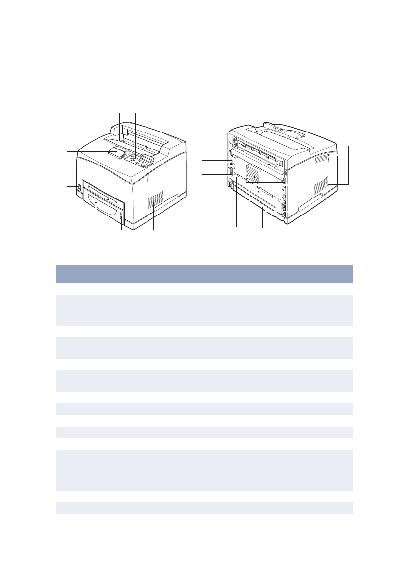
LOCATING PARTS OF THE PRINTER
The main parts of the printer and a brief description of their functions
are shown below:
2
1
8
7
13
11
14
12
3
654
3
39 10
No. Name Description
1 Centre output tray Print jobs are output here with printed side facing down.
2 Control panel Consists of the control buttons, indicators and display.
3 Ventilation slots Provide ventilation for the interior of the printer.
4 Paper level indicator Indicates the level of the remaining paper in the 550-
5 Tray 1 Holds 150 sheets of paper.
6 Tray 2 Holds 250 sheets (B6200) or 550 sheets (B6300) of
7 Power switch Switches the printer power on and off.
8 Extension output tray Pull this tray out when printing on paper larger than A4.
9 Duplex unit connector For connecting the duplex unit (option).
10 Power cord connector For connecting the power cord.
11 Parallel connector For connecting a parallel cable.
12 Network connector For connecting the network cable when using the printer
13 USB connector For connecting a USB cable.
14 Serial connector For connecting a serial cable.
For control panel details, refer to “The Control Panel and
Menu system” on page 43.
sheet paper tray.
paper.
as a network printer. (The Network Software Kit option
needs to have been installed to enable networking
capability.)
INSTALLATION AND RELOCATION PROCEDURE > 11
Page 12
PREPARING A LOCATION FOR THE PRINTER
Place the machine on a level and sturdy surface that can withstand the
machine weight – 20.4 kg (45lb) (B6200) or 22.6 kg (50lb) (B6300). If
tilted, the machine may fall over and cause injuries.
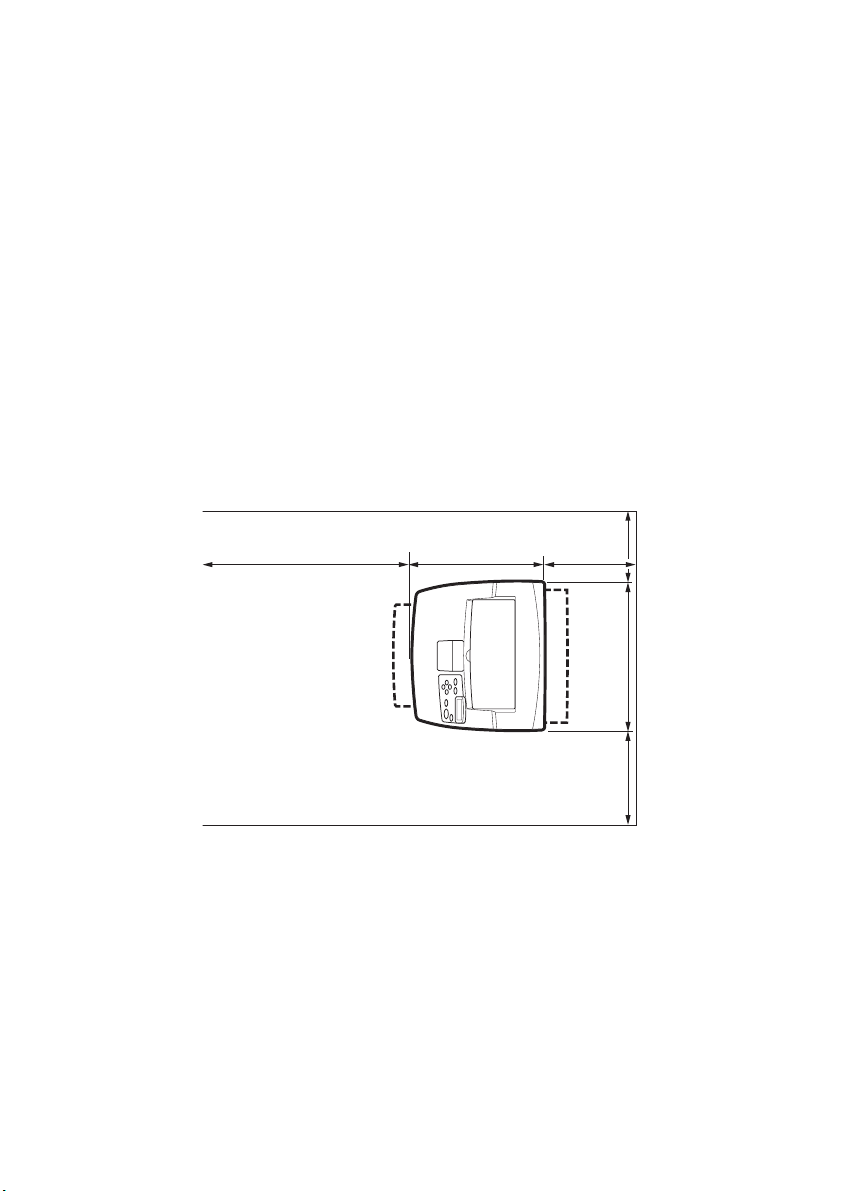
SPACE REQUIREMENTS
The printer has ventilation holes on the side and rear panels. Ensure
that the printer is installed with a minimum clearance of 255mm
(10in) from the rear vent to any wall, 200mm (8in) from the left vent to
any wall, and 300mm (12in) from the right vent to any wall. A poorly
ventilated machine can cause excessive internal heat and fire. The
following diagram shows the minimum clearances required for
normal operation, consumables replacement, and maintenance to
ensure your machine operates at peak performance.
200 mm
255 mm
513.2
mm
300 mm
* B6200
402 mm
465.4 mm
(454.6 mm)*
ENVIRONMENT
Ensure that the installation location meets the following conditions:
l Do not place the printer in a hot, humid, dusty or poorly
ventilated environment. Prolonged exposure to such adverse
conditions can result in fire or electric shock.
INSTALLATION AND RELOCATION PROCEDURE > 12
Page 13

l Temperature range 10 – 32 °C, humidity range 15 – 85% (no
condensation). Humidity should be 70% or below at 32 °C,
and temperature should be 28 °C or below at 85% humidity.
NOTE
Sudden temperature fluctuations can affect print quality. Rapid
heating of a cold room or moving the printer from a location with low
humidity/temperature to high humidity/temperature can cause
condensation inside the printer, directly interfering with image
transfer. When condensation occurs, leave the printer for at least 1
hour to acclimatise to the environment before using it.
l Do not expose the printer to direct sunlight.
l Do not expose the printer to the direct draught of air-
conditioning or heating.
INSTALLATION AND RELOCATION PROCEDURE > 13
Page 14
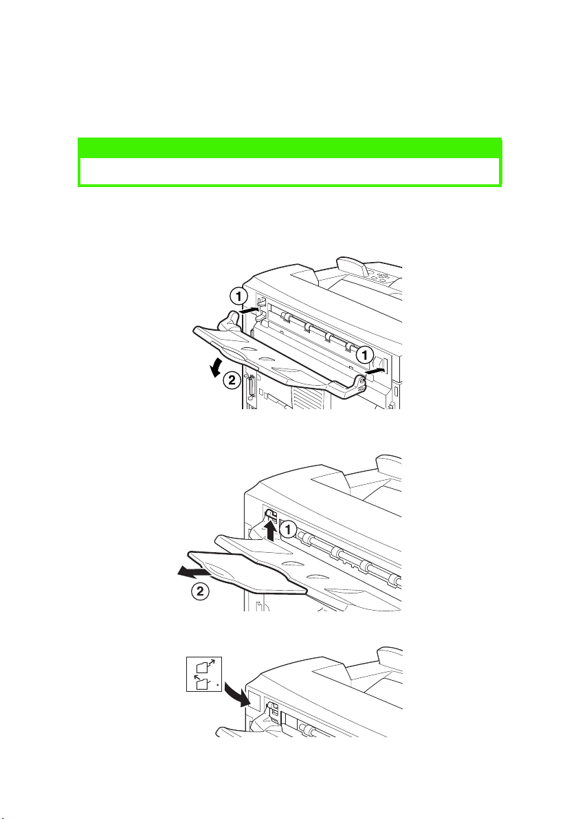
INSTALLING THE FACE UP (REAR) TRAY
You can install the face up (rear) tray on this printer if required.
NOTE
A face up (rear) tray can be installed on the B6300 only.
Insert the right and left tabs of the face up (rear) tray into the
1.
holes at the back of the printer (1), and lower the tray into
position (2).
Push up the rear output tray lever as shown in the diagram (1)
2.
and pull out the extension tray (2).
Affix the label provided to the back of the printer.
3.
INSTALLATION AND RELOCATION PROCEDURE > 14
Page 15

INSTALLING THE OPTIONAL ACCESSORIES
If you have purchased any optional accessories, install them before
setting the drum-toner cartridge and before loading paper. If there are
no optional accessories to install, proceed to the next section,
“Installing the Drum-Toner Cartridge” on page 35.
WARNING!
Never open or remove machine covers that are secured with screws
unless specifically instructed in this guide. A high voltage component
can cause electric shock.
Do not try to alter the machine configuration, or modify any parts. An
unauthorized modification can cause smoke or fire.
CAUTION!
Ensure the printer is switched off before connecting any interface
cables or options. Connecting cables or options to a live machine may
result in an electric shock.
NOTE
To add more optional accessories when the printer is in use, you need
to change the configuration of optional accessories in the printer driver.
For details, refer to the Online Help for the printer driver.
INSTALLATION AND RELOCATION PROCEDURE > 15
Page 16
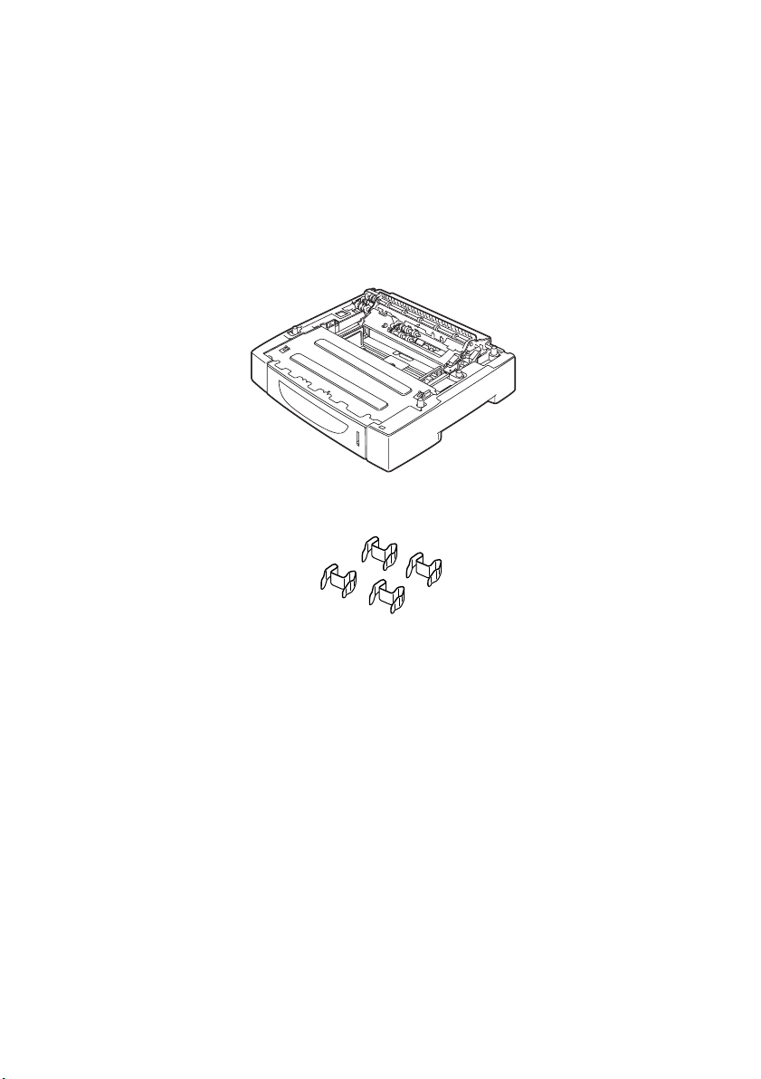
INSTALLING A UNIVERSAL TRAY
You can install up to two levels of universal tray (550-sheet) option to
this printer.
This section explains how to install two trays as an example.
Ensure that you have all of the following items:
1.
l Tray module and paper tray
l Fasteners (four pieces)
INSTALLATION AND RELOCATION PROCEDURE > 16
Page 17
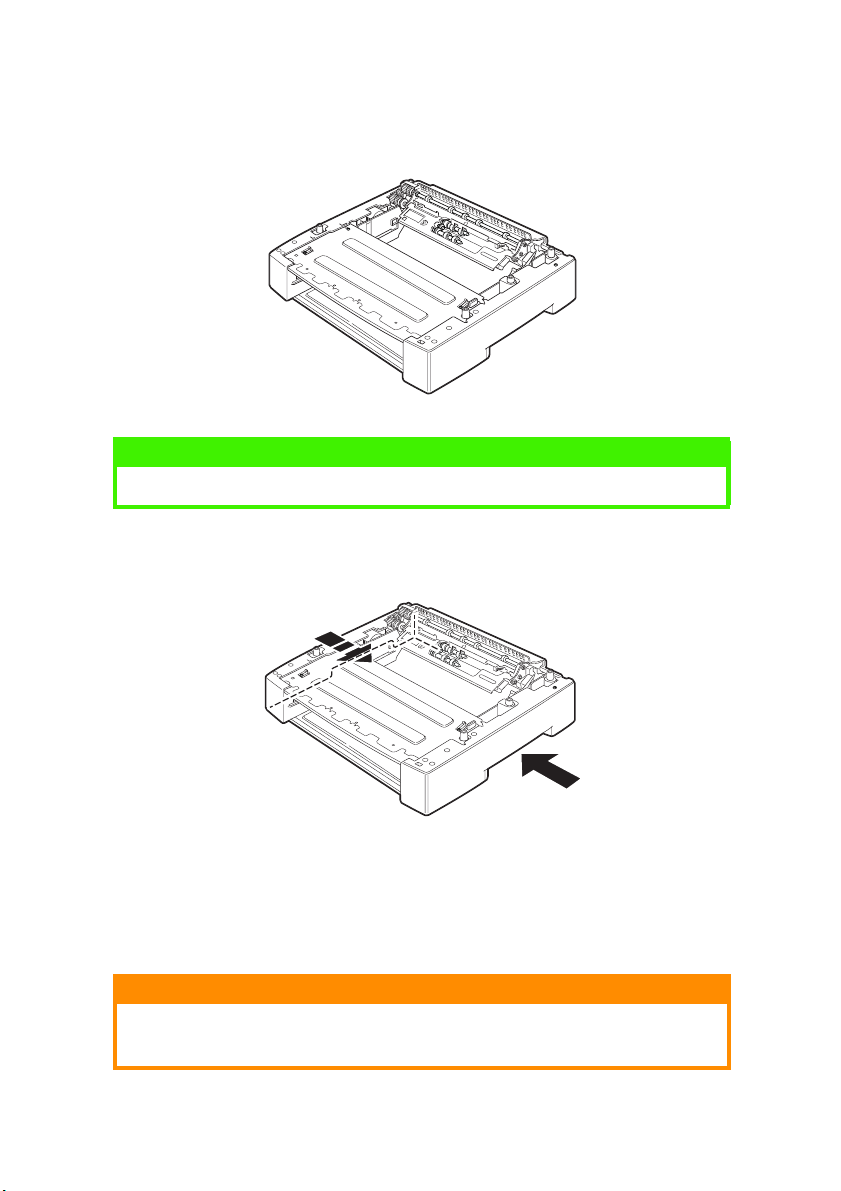
Place the tray module to be installed at the bottom level on a
2.
flat surface, then pull out the paper tray.
NOTE
Proceed to step 6 if you are installing only one tray module.
Lift the tray module to be installed at the top level by holding
3.
the parts as shown in the diagram.
Align the front and back corners of the top and bottom tray
4.
modules, and slowly lower the top module so that the guide
pins at the four corners of the bottom module fit into the holes
at the base plate of the top module.
CAUTION!
The tray module must be lowered gently. Otherwise, the interior parts
may be damaged.
INSTALLATION AND RELOCATION PROCEDURE > 17
Page 18
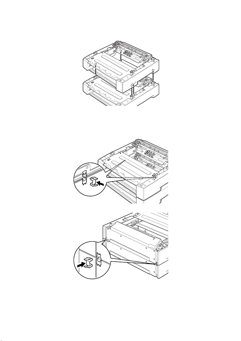
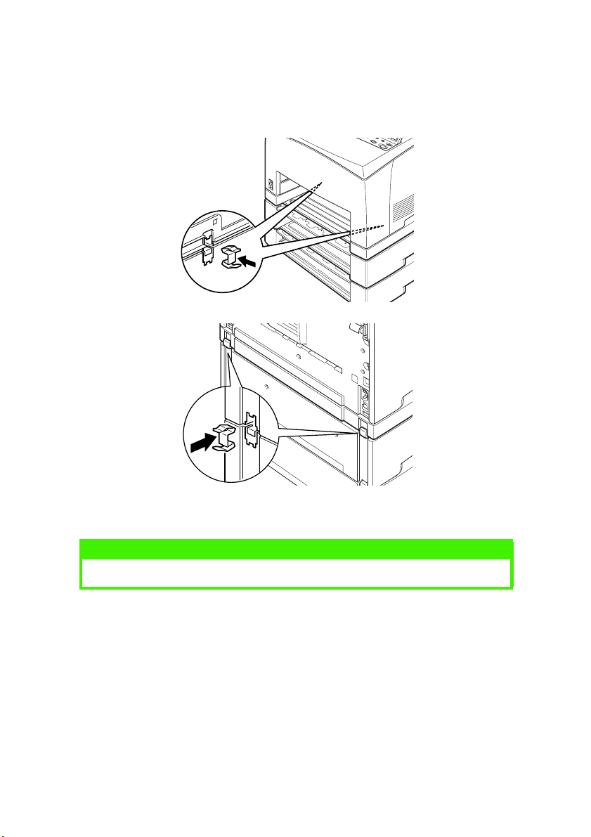
Insert the fasteners provided into the two locations inside the
5.
tray module and the two locations at the back of the tray
module. Insert the fasteners securely.
INSTALLATION AND RELOCATION PROCEDURE > 18
Page 19
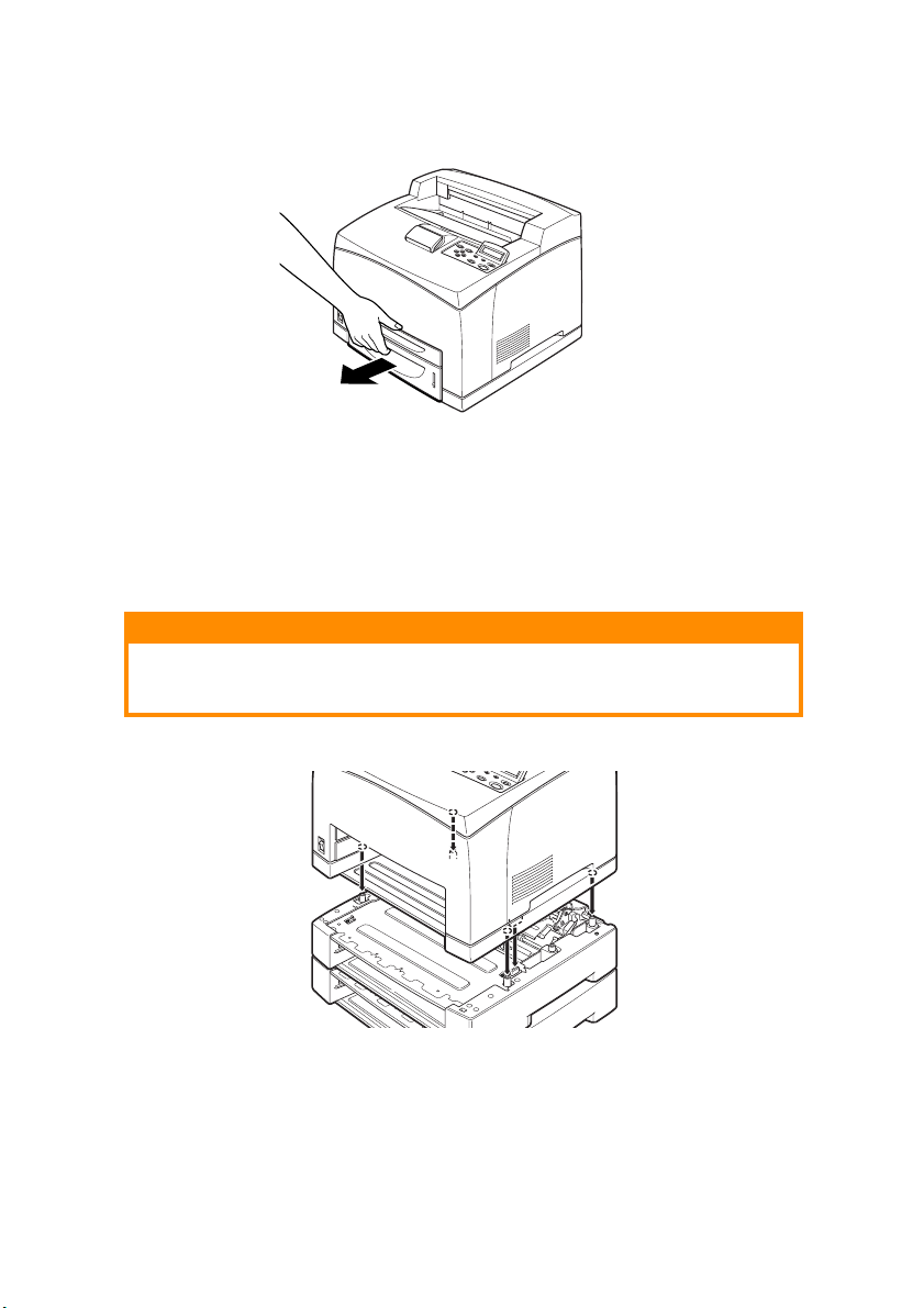
Pull the paper tray out of the printer.
6.
Lift up the printer by holding the recessed areas.
7.
Align the corners of the printer and the tray modules, and
8.
lower the printer gently so that the guide pins at the four
corners of the tray modules fit into the holes at the base plate
of the printer.
CAUTION!
The printer must be lowered gently. Otherwise, interior parts of the
tray modules may be damaged.
INSTALLATION AND RELOCATION PROCEDURE > 19
Page 20
Insert the fasteners provided into the two locations inside and
9.
the two locations at the back of the printer. Insert the fasteners
securely.
Push the tray completely into the printer.
10.
NOTE
For details on how to load paper, refer to “Loading paper” on page 40.
INSTALLATION AND RELOCATION PROCEDURE > 20
Page 21

INSTALLING THE DUPLEX UNIT
You can install a duplex unit option on this printer. If a face up tray has
been fitted, remove it by reversing the steps in “Installing the Face Up
(Rear) Tray” on page 14 before installing the duplex unit and refit it
when the duplex unit has been installed.
Remove the duplex unit cover by pushing the two tabs as
1.
shown in the diagram (1).
Next, remove the connector cap at the top right of the back of
the printer (2).
Insert the right and left tabs at the bottom of the duplex unit
2.
into the holes at the back of the printer, and then align the top
part of the duplex unit with the printer.
Ensure that the connector of the duplex unit is connected to
the connector of the printer.
INSTALLATION AND RELOCATION PROCEDURE > 21
Page 22

Tighten the screws at both ends of the bottom of the duplex
3.
unit.
INSTALLATION AND RELOCATION PROCEDURE > 22
Page 23

INSTALLING THE OFFSET CATCH TRAY
You can install an offset catch tray option on this printer.
NOTE
An offset catch tray can be installed on the B6300 only.
Lift the second lever on the top left corner at the back of the
1.
printer (1), and open the cover (2).
NOTE
When the duplex unit is installed, lift the lever on top of the left side
cover of the unit and open the unit, then open the cover as shown in
the diagram.
INSTALLATION AND RELOCATION PROCEDURE > 23
Page 24

Loosen the right and left thumbscrews as shown in the
2.
diagram to uninstall the top cover of the paper exit.
Insert the right and left tabs of the offset catch tray into the
3.
holes at the top of the printer (1) and lower it slowly onto the
top of the printer (2).
Secure the screws at both ends of the bottom of the offset
4.
catch tray.
INSTALLATION AND RELOCATION PROCEDURE > 24
Page 25

Close the cover.
5.
If you install the face up (rear) tray on the printer, affix the
6.
label provided to the back of the offset catch tray.
Pull out the extension tray.
7.
CAUTION!
Printing while the tray is folded up may cause a paper jam. Be sure to
open the tray when using the printer.
Flip up the stopper when printing on heavy weight papers.
8.
INSTALLATION AND RELOCATION PROCEDURE > 25
Page 26

INSTALLING A NETWORK SOFTWARE KIT, HARD DISK, COMPACT FLASH DISK, OR ADDITIONAL MEMORY
To install a Network Software Kit, Hard Disk, Compact Flash Disk or
Additional Memory, the same steps are required at the beginning, to
prepare the printer, and at the end, to close the printer, of each
installation. These steps are described here.
Preparing the printer
Remove the screw on the right detachable cover.
1.
Slide the cover towards the back of the printer (1) to release
2.
the protrusions at the bottom and pull it downwards (2).
INSTALLATION AND RELOCATION PROCEDURE > 26
Page 27

Remove the two screws on top of the metal cover (1), and pull
3.
the metal cover upwards (2).
Closing the printer
Align and insert the protrusion at the bottom of the metal
1.
cover into the notch of the printer (1), and tighten the two
screws on the top of the cover (2).
Align and insert the protrusions at the top of the right
2.
detachable cover into the notches of the printer (1). Fit the
protrusions at the bottom of the cover into the printer (2) and
slide the cover towards the front of the printer (3).
Tighten the screw on the right detachable cover.
3.
INSTALLATION AND RELOCATION PROCEDURE > 27
Page 28

INSTALLING A NETWORK SOFTWARE KIT
You can install a network software kit option on this printer. Installing
this option may initialise the settings of [Network/Port] and [Allocate
Memory].
CAUTION!
Never touch the connectors of the network software kit.
Never allow the network software kit to be bent or damaged.
Before handling the network software kit, touch something metal in
order to discharge any electrostatic charge built up in your body.
Refer to “Preparing the printer” on page 26.
1.
Hold the network software kit so its notch (1) is aligned with
2.
the protrusion on the slot.
Release the hook on the top of the slot.
3.
Gently insert the network software kit into the slot, and press
4.
firmly at the top corner of the card then at the bottom corner.
INSTALLATION AND RELOCATION PROCEDURE > 28
Page 29

Inserting the network software kit fully and securely into the
slot will cause the hook on the top of the slot to rise.
NOTE
Be sure to insert the network software kit securely into the slot as far
as it will go.
Remove the cap from the network connector.
5.
Refer to “Closing the printer” on page 27.
6.
INSTALLATION AND RELOCATION PROCEDURE > 29
Page 30

INSTALLING A HARD DISK
You can install a hard disk option on this printer.
NOTE
> When the Compact Flash disk (option) is installed on your printer,
you cannot install the hard disk. You can install only one of them.
> Installing this option may initialise the settings of [Network/Port]
and Allocate Memory].
CAUTION!
The hard disk is a delicate item and must be handled with care. In the
event that damage does occur, it may erase important data saved on
the disk. It is recommended that you back up your data regularly.
Refer to “Preparing the printer” on page 26.
1.
Remove the screws on the right and left sides of the Compact
2.
Flash disk drive (1) and remove the Compact Flash disk drive
as shown in the diagram (2).
Remove the cable of the Compact Flash disk drive from the
3.
connector on the printer.
INSTALLATION AND RELOCATION PROCEDURE > 30
Page 31

Connect the cable of the hard disk to the connector on the
4.
printer as shown in the diagram.
CAUTION!
When connecting the cable, hold the disk firmly by hand to prevent it
from dropping.
Hold the hard disk as shown in the diagram, and install it in
5.
the printer. Align the arrow on the hard disk with the arrow on
the printer, and insert the bracket at the top of the disk into
the install position.
Tighten the screws on both sides of the hard disk.
6.
Refer to “Closing the printer” on page 27.
7.
INSTALLATION AND RELOCATION PROCEDURE > 31
Page 32

INSTALLING A COMPACT FLASH DISK
You can install a Compact Flash disk option (only available in certain
regions) to this printer.
NOTE
> When the hard disk (option) is installed on your printer, you cannot
install the Compact Flash disk. You can install only one of them.
> Installing a Compact Flash disk erases any data that resides in the
Compact Flash disk.
> Installing this option may initialise all the printer settings for
allocating memory.
Refer to “Preparing the printer” on page 26.
1.
Open the fastener on the Compact Flash disk drive.
2.
Locate the Compact Flash disk as shown in the diagram.
3.
INSTALLATION AND RELOCATION PROCEDURE > 32
Page 33

Close the fastener.
4.
Refer to “Closing the printer” on page 27.
5.
INSTALLATION AND RELOCATION PROCEDURE > 33
Page 34

INSTALLING ADDITIONAL MEMORY
The additional memory module for this printer is 512MB.
CAUTION!
Do not touch the terminal area of the additional memory.
Do not bend or damage the additional memory.
Be sure to place the additional memory in contact with a metal
surface to eliminate static shock before touching it with your bare
hands.
To add more memory when the printer is in use, you need to configure
the memory capacity in the printer driver. For details, refer to the
Online Help for the printer driver.
Refer to “Preparing the printer” on page 26.
1.
Hold the additional memory so that the notch (1) is aligned
2.
with the protrusion on the slot.
Insert the additional memory at an angle (1) and push it into
3.
the printer until it clicks into position (2).
NOTE
Ensure that the additional memory is firmly inserted.
Refer to “Closing the printer” on page 27.
4.
INSTALLATION AND RELOCATION PROCEDURE > 34
Page 35

INSTALLING THE DRUM-TONER CARTRIDGE
NOTE
Your printer is supplied with a drum-toner cartridge with capacity
6,000 A4 pages at 5% coverage. Replacement drum-toner cartridges
are available with capacity 10,000 pages (B6200/B6300) or 17,000
pages (B6300 only).
When handling the drum-toner cartridge, take note of the following
points:
WARNING!
Never throw a drum-toner cartridge into an open flame as it can cause
an explosion.
l Do not subject the drum-toner cartridge to direct sunlight or
strong light.
l When installing the drum-toner cartridge, select a location not
subject to strong light and try to finish the installation within
5minutes.
l Do not touch the surface of the photosensitive drum. Do not let
the drum-toner cartridge stand upside down or place it upside
down as this may damage the drum.
l A drum shutter protects the photosensitive drum from light.
Do not open the drum shutter.
l Although the toner is not harmful to the body, wash it off
immediately if your hands or clothes are in contact with it.
INSTALLATION AND RELOCATION PROCEDURE > 35
Page 36

l It is recommended to use up the drum-toner cartridge within
one year of removing it from its packaging.
l Keep the drum-toner cartridge out of the reach of children.
Open the cover.
1.
NOTE
When the optional offset catch tray is installed, fold the tray first
before opening the cover.
WARNING!
Do not touch any parts inside the printer.
Take the drum-toner cartridge out of the packaging box and
2.
shake it seven or eight times as shown in the diagram.
INSTALLATION AND RELOCATION PROCEDURE > 36
Page 37

Place the drum-toner cartridge on a flat surface and pull out
3.
the seal horizontally.
CAUTION!
When pulling out the seal, pull it out horizontally. The tape might
break if it is pulled out diagonally.
After the seal has been pulled out, do not shake or bump the drumtoner cartridge.
Hold the drum-toner cartridge by the grip and insert it into the
4.
slot inside the printer.
CAUTION!
Do not touch any parts inside the printer.
Ensure that the drum-toner cartridge is firmly located.
Close the cover securely.
5.
NOTE
If the offset catch tray is folded as in Step 1, close the cover and then
return the tray to its original position.
INSTALLATION AND RELOCATION PROCEDURE > 37
Page 38

CONNECTING AN INTERFACE CABLE
Connect the interface cable to be used to the printer.
NOTE
Connect a USB cable only after the printer driver has been installed on
the computer.
Connect the interface cable to the interface connector at the
1.
back of the printer: serial (1), USB (2), network (3), parallel (4).
For a parallel cable, lift up the wire clip on both sides to secure
it after it has been inserted into the connector.
For Parallel, USB, or Serial cables, connect the other end of the
2.
cable to the interface connector of the computer.
INSTALLATION AND RELOCATION PROCEDURE > 38
Page 39

CONNECTING THE POWER CORD
When connecting the power cord, take heed of the information given
in “Safety precautions” on page 9.
Ensure that the
1.
printer power
switch is in the <{>
position.
Connect the power
2.
cord to the power
cord connector at
the back of the
printer. Connect the
other end of the
power cord to the
power outlet.
Press the power
3.
switch of the
printer to the < >
position.
The power will be
applied and the
control panel will
display that the
printer is ready to
print.
NOTE
> Depending on the network environment used, it may take some
minutes before the printer is ready for printing.
> If the message that the printer is ready to print but is unable to
retrieve an IP Address is displayed, continue operating as normal.
INSTALLATION AND RELOCATION PROCEDURE > 39
Page 40

LOADING PAPER
This section explains how to load A4 size plain paper in portrait
orientation in the paper tray.
Portrait
orientation
Place the paper tray on a flat surface and remove the lid.
1.
If the base plate of the paper tray is raised, push it down.
2.
INSTALLATION AND RELOCATION PROCEDURE > 40
Page 41

Squeeze the length guide and slide it to the desired paper size
3.
(1). Squeeze the right width guide and slide it to the desired
paper size (2).
Load the paper with the side to be printed facing up and with
4.
all four corners aligned.
CAUTION!
Do not place paper over the right width guide.
Do not load paper exceeding the maximum fill line or the maximum
capacity allowed.
Align the right width guide with the paper width correctly. If the right
width guide is not in place, the paper will not be properly fed and this
may cause paper jams.
INSTALLATION AND RELOCATION PROCEDURE > 41
Page 42

Close the lid of the paper tray and push the tray completely
5.
into the printer.
CAUTION!
The lid of the tray must be firmly closed. If not, the paper may become
misaligned.
Depending on the types and sizes of the loaded paper, you
6.
need to configure settings on the control panel.
Change the paper type when non-plain paper such as recycled
paper, heavyweight paper or transparencies are loaded.
Configure the paper size when custom size paper is loaded.
INSTALLATION AND RELOCATION PROCEDURE > 42
Page 43

THE CONTROL PANEL AND MENU SYSTEM
For full details on the control panel and menu structure, refer to the
Reference Guide.
The control panel components and their functions are described
below:
12
354
6
89
7
No. Name Description
1 <MENU> button Press to display/close the menu screen.
2 <FEED/SELECT> button Press to set the required menu value and use to print
3 <READY> indicator When illuminated, the printer is ready to receive data
4 LCD Display Displays menu values, printer status and error messages.
5 <ATTENTION> indicator When illuminated, there is a malfunction in the printer.
6 <POWER SAVE>
button/indicator
7 <CANCEL> button Press to cancel printing.
8 <ON LINE> button Press to enter offline status, in which the printer cannot
reports/lists.
from the computer.
Press to enter/exit power save mode. The indicator is
illuminated when the printer is in power save mode.
receive data or process printing data. Press again to exit
offline status and enter online status, in which the printer
can receive data from the computer.
INSTALLATION AND RELOCATION PROCEDURE > 43
Page 44

No. Name Description
9
<> <> <> <>
buttons
Press these to move to the required menu, item and
required value on the display. Also, press the < > button
when you are carrying out secure/sampled/delayed
printing or when you are checking/printing received mail
manually.
Note: When you are changing the candidate values by the
< > < > buttons, you can press and hold down the
buttons to change the display continuously. Also,
pressing the < > < > buttons simultaneously displays
the default values.
NAVIGATING THE CONTROL PANEL MENUS
Display/Close the Menu
screen
Switch between the menu
levels
Switch between menus or
items in the same level
Move the cursor (_) of the
setting value to the right or
left
Confirm setting <FEED/SELECT> button
<MENU> button
< > button (moves one level downwards) or < > button
(moves one level upwards)
< > button (displays the previous menu or item) or < >
button (displays the next menu or item)
< > button (moves to the right) or < > button (moves to
the left)
When you press the MENU button on the control panel, you enter the
printer’s menu system. At that point, the first line of the display
contains the text [Menu], indicating that you are in the menu system.
The second line of the display lists the active menu, which you can
change by pressing the < > or < > button.
Using these buttons repeatedly, you can cycle through the main
menus in the following order: Print Language; Report/List; Meter
Reading; Admin Menu; Display Language.
By using the arrow buttons as indicated above, you can navigate
through the menu system to make any required settings. For example,
to set the paper type in Tray 1 to accommodate recycled paper,
navigate as follows: Admin Menu, Printer Settings, Paper Type, Tray 1,
Recycled then press the <FEED/SELECT> button to record the setting
and the <MENU> button to close the menu screen.
INSTALLATION AND RELOCATION PROCEDURE > 44
Page 45

SELECTING THE CONTROL PANEL LANGUAGE
English is the default language for all error and status messages;
however, these messages are also available in many languages. Use
the following procedure to change the display language.
NOTE
Refer to the section “The Control Panel and Menu system” on page 43
for a brief overview of the control panel and its menus and sub-menus.
Press the <MENU> button to display the Menu screen.
1.
Press the <> or <> button until [Display Language] is
2.
displayed, then press the < > button.
Press the < > or < > button until the required language is
3.
displayed, then press the <FEED/SELECT> button.
Press the <MENU> button to complete the language setting.
4.
INSTALLATION AND RELOCATION PROCEDURE > 45
Page 46

PRINTING A CONFIGURATION SUMMARY
To check whether the printer is correctly installed, use the control
panel to print the [System Settings List].
NOTE
If you have made a mistake when operating the control panel, press
the <MENU> button to restart. For details on how to operate the control
panel, refer to “The Control Panel and Menu system” on page 43.
Press the <MENU> button to display the Menu screen.
1.
Press the < > or < > button until [Report/List] is displayed,
2.
then press the < > button.
Press the < > or < > button until [System Settings] is
3.
displayed, then press the < > button.
Press the <FEED/SELECT> button.
4.
The [System Settings List] will be printed.
Press the <MENU> button when printing has completed.
5.
NOTE
> The layout of the [System Settings List] may differ depending on
the configuration and settings of the printer.
> For B6300, [Rear Output Tray] is displayed in the column for Output
Device even when the rear tray is not installed.
> Reports/lists cannot be output to the face up (rear) tray. When the
face up (rear) tray is installed, lower the face up (rear) tray output
lever.
INSTALLATION AND RELOCATION PROCEDURE > 46
Page 47

SETTING PRINTER CONFIGURATIONS VIA A WEB PAGE
Via a Web page facility, you can make use of a web browser in a TCP/
IP-enabled environment to display the printer or job printing status
and to change the settings.
Among the printer settings that are made on the control panel,
settings for the system and network ports can be configured under
[Printer], [Network] and Maintenance] on the Web page.
NOTE
> The Web page facility is only available when the printer is connected
to the network.
> Refer to the Reference Guide when the Web page does not appear
after carrying out the steps 1 and 2 below.
> You can also use Telnet to set the printer configuration. For details
on the settings, refer to the NIC Configuration Guide.
Boot your computer, and start the Web browser.
1.
Enter the printer’s IP address or URL in the address input
2.
column on the Web browser and press the <Enter> key.
Using Online Help
For details regarding the items that can be set in each screen, click the
[Help] button to display the Online Help.
INSTALLATION AND RELOCATION PROCEDURE > 47
Page 48

INSTALLING THE PRINTER DRIVER
To print from the computer, install the printer driver and other
required software.
The installation procedure(s) you will use for your printer vary
according to operating system, usage of the USB port, and network
connection.
A brief outline of installing drivers on Windows and Macintosh
operating systems is given below. Solaris, Linux and HP-UX are dealt
with in other parts of your documentation.
MICROSOFT WINDOWS SYSTEMS
With Windows running, insert the CD-ROM into your CD-ROM
1.
drive.
If the CD-ROM does not run automatically, use [Start – Run...]
2.
and enter E:\setup (where E is your CD-ROM drive) in the Open
field.
Click on OK.
3.
Click on [Driver Installation] and then [Install Printer Driver]
4.
and follow the on-screen prompts to complete your printer
driver installation.
APPLE MAC OS 8X, 9X (USB)
Ensure that the printer and the host computer are powered on.
1.
Ensure that the “Apple LaserWriter Software” is installed.
2.
Attach the USB cable to the host computer and the printer.
3.
NOTE
The printer is considered a “self-powered” device and as such may be
plugged into any available USB port on the Macintosh, including the
one on the keyboard.
Open the [Desktop Printer Utility] (installed when you installed
4.
the Apple LaserWriter Software).
INSTALLATION AND RELOCATION PROCEDURE > 48
Page 49

Choose the correct driver to use, depending on the printer you
5.
are installing.
Choose [Printer (USB)] and press OK.
6.
Choose the PPD file that corresponds to your printer.
7.
Choose the correct printer.
8.
Press [Create].
9.
You now have a desktop shortcut to the USB printer and are
10.
ready to print.
MACINTOSH OS X
The installer program is a “unified” installer. This means that the
same program runs on both Mac OS X and Mac OS 9.x and earlier. It
should work intelligently and display only the appropriate options for
your system.
Place the software CD-ROM in the CD-ROM drive.
1.
Double-click the CD icon.
2.
Double-click [Language Folder].
3.
Double-click the [Install Oki Software] shortcut icon.
4.
This launches the installer program. Follow the on-screen
instructions. Default state installs all drivers: deselect those not
required.
If you wish to find out more about the software that is included, please
refer to the help facility.
INSTALLATION AND RELOCATION PROCEDURE > 49
Page 50

SETTING THE CONFIGURATION OF OPTIONAL ACCESSORIES AND PAPER
After the printer driver has been installed, configure settings for
optional accessories and paper types/sizes loaded in each tray under
the [Options] tab of the printer driver. For details, refer to the Online
Help for the printer driver or the Reference Guide. The procedure to
display the [Options] tab is as follows, using Windows XP as an
example:
Click [Start] on the taskbar, then select [Printers and Faxes].
1.
Click the icon of this printer, and then select [Properties] from
2.
the [File] menu.
Click the [Options] tab.
3.
PRINTING A TEST DOCUMENT
After completing the installation procedure, verify that the printer is
working correctly by printing a document from an application.
INSTALLATION AND RELOCATION PROCEDURE > 50
Page 51

IF PAPER JAMS
CAUTION!
When removing jammed paper, make sure that no pieces of torn
paper are left in the machine. A piece of paper remaining in the
machine can cause a fire. If a sheet of paper is wrapped around the
heat roller, or when clearing a jammed paper that is difficult or
impossible to see, do not try to remove it by yourself. Doing so may
cause injuries or burns. Switch off the machine immediately, and
contact your Oki dealer.
Guided by the message on the control panel, open the cover and
remove the jammed paper. If paper is torn, check for any remaining
torn pieces of paper.
CAUTION!
The fuser unit gets hot when operating. Avoid touching it.
The covers and trays are identified in the following diagram:
D
A
B
C
Cover A
first before opening cover A. When a message to remove the drumtoner cartridge is displayed, refer to “Inside Cover A” on page 53.
: When the optional offset catch tray is installed, fold the tray
IF PAPER JAMS > 51
Page 52

Cover B
:
NOTE
Remove the rear tray (if fitted) when opening the back cover.
Open Cover B (For B6300, raise the lever as shown in the diagram and
open cover B (1)). After opening cover B, hold the part marked with a *,
open the cover of the fuser unit (2) and remove any jammed paper.
Cover C
(Duplex Unit):
NOTE
Remove the rear tray (if fitted) when opening the back cover.
Push up the lever (1) to open the duplex unit cover.
IF PAPER JAMS > 52
Page 53

Cover D
Offset catch tray:
Paper Tray
paper. Refer to “Inside the Paper Tray” on page 54.
: Pull out the tray and follow the procedure to remove
INSIDE COVER A
Follow the procedure below to remove any jammed paper when the
control panel indicates either [Paper jam Open Cover A] or [Remove
cartridge Clear jam]:
Open cover A, and holding the drum-toner cartridge by the
1.
grip, remove it from the printer (1).
Turn the roller as shown in the diagram and remove any
2.
jammed paper inside (2).
IF PAPER JAMS > 53
Page 54

Return the drum-toner cartridge and Cover A to their original
3.
positions.
CAUTION!
When the optional offset catch tray is installed, close Cover A first
before returning the tray to its original position.
If you continue to print with the offset catch tray folded, this may cause
a paper jam. Always use the printer with the tray open.
INSIDE THE PAPER TRAY
Follow the procedure below to remove any jammed paper when the
following messages are displayed intermittently: [Pull out all trays.
Clear jam] and [Clear jam and close Cover A]:
Pulling out the paper trays:
Pull out all paper trays and remove any wrinkled paper.
1.
Examine the inside of the printer and remove any jammed
2.
paper.
IF PAPER JAMS > 54
Page 55

After removing the paper:
Push the paper trays completely back into the printer.
1.
Open and close Cover A to clear the error message.
2.
IF PAPER JAMS > 55
Page 56

ERROR MESSAGES
If an error message is displayed at the control panel, follow the
instructions to fix the error. Depending on the message content,
follow the instructions in the Reference column below to fix the error.
Message content Reference
An error code xxx-xxx is
displayed.
Paper jam or “Remove
paper” is displayed.
Installing and replacing the
drum-toner cartridge
Loading and replenishing
paper
The following section explains the contents and actions required for
the more complex messages. For details on messages not described
here, refer to the Reference Guide.
Message Condition/Reason/Action
Corrupt HDD File.
Press SEL key
Refer to the Reference guide for a list of error codes.
Refer to “If paper jams” on page 51.
Refer to procedures described on the consumables
packaging box or “Installing the Drum-Toner Cartridge” on
page 35.
Refer to “Loading paper” on page 40.
When the hard disk (option) is installed, the printer assumes that
data in the hard disk is corrupted if power is cut off when the
printer is in use.
Press the <FEED/SELECT> button on the control panel. The hard disk
will be initialised.
Corrupt Log file
Press SEL key
Incorrect paper
type Reselect
SEL to print
CANCEL to cancel
Initialising the hard disk will delete data for registered forms,
logos, secure print, and PostScript download fonts.
When the hard disk (option) is installed, the printer assumes that
data in the hard disk is corrupted if power is cut off when the
printer is in use.
Press the <FEED/SELECT> button on the control panel. The log file
will be initialised.
It can take 1 minute to initialise the log file. Do not switch off the
power of this printer when initialisation is in progress.
Paper of the type specified under [Paper Type] in the printer driver
is not loaded in the trays. Press the <FEED/SELECT> button on the
control panel to print on paper of another type or press <CANCEL>
to cancel the job.
ERROR MESSAGES > 56
Page 57

Message Condition/Reason/Action
Off-line
Off-line
Data in memory
Ready to print
DNS Update Fail
Ready to print
Get IP Add. Fail
Ready to print
Repl. Drum/Toner
The printer is off-line as the <ON LINE> button has been pressed. To
cancel the off-line status, press the <ON LINE> button again.
The printer cannot receive any print data from the computer while
it is off-line.
Unable to retrieve IP address from DNS.
Check the settings for DNS and retrieving IP address.
Failed to retrieve IP address from DHCP server.
Change the retrieving method for IP address and manually set the
IP address.
Refer to the Reference Guide.
The drum/toner cartridge is about to be replaced. Prepare a new
drum/toner cartridge. You can still print about another 100 pages
even when this message is displayed.
ERROR MESSAGES > 57
Page 58

INDEX
A
arrow buttons .............................44
C
connecting interface cables.........38
Connecting power cord ...............39
E
Error Messages (control panel) ....56
F
<FEED/SELECT> button .................44
I
Installing Additional Memory.......34
Installing the Drum/Toner
Cartridge ...................................35
Installing the Optional
Accessories ...............................15
installing the printer ...................12
L
loading paper
loading paper in paper tray ......40
P
paper tray...................................54
Printer driver
Install .....................................48
printing reports/lists...................46
S
Setting Configuration of Optional
Accessories ...............................50
system settings list.....................46
W
Web page facility
Using Online Help.................... 47
When Paper Jams ........................51
When Problems Occur
When Condensation Occurs .....13
M
<MENU> button............................ 44
Menu Items on the
Control Panel .............................43
O
Online Help (Web page facility)....47
[Options] tab ..............................50
INDEX > 58
Page 59

OKI CONTACT DETAILS
Oki Systems (UK) Limited
550 Dundee Road
Slough Trading Estate
Slough, SL1 4LE
Tel:44 (0) 1753 819819
Fax:44 (0) 1753 819899
http://www.oki.co.uk
Oki Systems Ireland Limited
The Square Industrial Complex
Tallaght, Dublin 24, Ireland
Tel:+353 1 4049590
Fax:+353 1 4049591
http://www.oki.ie
OKI Systems (Ireland) Ltd
40 Sydenham Park
Belfast, BT4 1PW
Tel:+44 44 (0)28 90 20 1110
http://www.oki.ie
Technical Support for all of
Ireland:
Tel : +353 1 4049570
Fax: +353 1 4049555
E-mail: tech.support@oki.ie
Oki Data Corporation
4-11-22 Shibaura, Minato-ku,
Tokyo 108-8551, Japan
Tel : (81) 3 5445 6158
Fax : (81) 3 5445 6189
http://www.okidata.co.jp
Oki Data (Singapore) Pte. Ltd.
78 Shenton Way, #09-01,
Singapore 079120
Oki Systems (Thailand) Ltd.
956 Udomvidhya Building 6th
Floor, Rama IV Rd., Bangkok
10500, Thailand
Tel : (662) 636 2535
Fax: (662) 636 2536
http://www.okisysthai.com
Oki Hong Kong Limited
Suite 1909, Tower3,
China Hong Kong City,
33 Canton Rd., Tsimshatsui,
Kowloon, Hong Kong
Tel: (852) 2736 0130
Fax : (852) 2376 3725
The IPL Group
63-85 Victoria Street
Beaconsfield NSW 2015,
Australia
Tel : (61) 2 9690 8200
Fax : (61) 2 9690 8300
http://www.oki.com.au
Comworth Systems Ltd.
10 Constellation Drive Mairangi
Bay, Auckland,
New Zealand
Tel : (64) 9 477 0500
Fax : (64) 9 477 0549
http://www.comworth.co.nz
Tel: (65) 221 3722
Fax : (65)421 1688
http://www.okidata.com.sg
OKI CONTACT DETAILS > 59
Page 60

LIMITED WARRANTY: UNITED STATES AND CANADA
Oki Data Americas, Inc. (Oki Data) warrants this printer to be free from
defects in material and workmanship and will remedy any such defect
according to the terms of this Limited Warranty.
Oki Data will repair (or at its option, replace) at no charge, any
defective component(s) of the Printer for one (1) year from the date of
purchase. This Limited Warranty extends to the original purchaser
only. This Limited Warranty does not extend to consumable items.
ON-SITE REPAIR
: On-Site Repair is available in the United States and
Note
Canada only. On-Site Repair does not include the replacement
or repair of product consumables or supplies.
Oki Data will, for a period of one (1) year from the date of
original purchase, repair or replace (at Oki Data's option) onsite at the original purchaser's facility and without charge, any
defective component(s) of the printer, provided that the
warranty service is performed by an Oki Data authorized
service provider. Oki Data reserves the right to use new and/or
refurbished parts in the warranty repair process.
As a condition of this Limited Warranty, requests for On-Site
Repair must include the name and phone number of a fully
competent and responsible adult with the authority to consent
to the entry of the servicing technician to the premises where
the printer is located, and who will remain with the servicing
technician while the service work is performed. Any and all
dangerous conditions must be removed from the site prior to
and throughout the time a service technician is present. The
service technician may refrain from entering the premises or
continuing to provide services at any site, if in the servicing
technician's reasonable judgement the site poses a risk of
physical harm or danger. If warranty services cannot be
performed or completed due to any of the foregoing reasons
the On-Site service option is null and void and the product
must be returned to an authorized Oki Data service location for
warranty repair service.
LIMITED WARRANTY: UNITED STATES AND CANADA > 60
Page 61

To make request or claim for service under this Limited Warranty
contact your local Oki Data authorized service center or Oki Data at
1-800-OKI-DATA (1-800-654-3282).
A written receipt for the product, showing the date of purchase,
dealer’s name, and both the model and serial numbers of this printer
must accompany any request or claim for work to be performed under
this Limited Warranty.
This Limited Warranty shall not apply if the product has been
damaged due to abuse, misuse, misapplication, accident, or as a
result of service or modification by any other than an authorized Oki
Data service center.
THERE ARE NO EXPRESS WARRANTIES OTHER THAN THOSE ON THE
FACE HEREOF AND DESCRIBED ABOVE. NO WARRANTIES WHETHER
EXPRESS OR IMPLIED, INCLUDING, BUT NOT LIMITED TO, ANY IMPLIED
WARRANTIES OF MERCHANTABILITY OR FITNESS FOR A PARTICULAR
PURPOSE, SHALL EXTEND BEYOND THE RESPECTIVE WARRANTY
PERIOD DESCRIBED ABOVE. Some states do not allow limitations on
how long an implied warranty lasts, so the above limitation may not
apply to you.
OKI DATA SHALL NOT BE RESPONSIBLE OR LIABLE FOR ANY SPECIAL,
INCIDENTAL OR CONSEQUENTIAL DAMAGES OR LOSS ARISING FROM
THE USE OF THIS PRODUCT. Some states do not allow the exclusion or
limitation of incidental or consequential damages, so the above
exclusion may not apply to you.
Additional information on obtaining service under this Limited
Warranty is available by contacting the Oki Data dealer from whom
the product was purchased, by contacting Oki Data directly at
1-800-654-3282 (1-800-OKI-DATA) [U.S. and Canada, English only] or
at 1-856-222-7496 (Spanish only), or by contacting the service
location listed below.
This Limited Warranty applies to this printer. However, the procedure
for obtaining service may vary outside the continental United States.
Contact your Oki Data dealer for such warranty service information.
This warranty gives you specific legal rights, and you may also have
other rights which vary from state to state.
LIMITED WARRANTY: UNITED STATES AND CANADA > 61
Page 62

OVERNIGHT EXCHANGE: UNITED STATES AND CANADA
If you choose to use our Overnight Exchange service, call 1-800-OKIDATA: our trained personnel will try to solve your problem over the phone.
If they determine that your product is defective, an exchange product will
be shipped to you via air express. Have your credit card available, as our
representative will be asking for this information. You will receive the
exchange product the next business day — or no later than the second
business day.
Return the original product to Oki Data by using the same packaging
materials you received with the exchange product. The product to be
returned must be made available for pickup by Oki Data’ s representative
within 2 business days of your receipt of the exchange product: failure to
do so may result in your being charged the full price of the exchange unit.
When Overnight Exchange is used, the returned machine becomes the
property of Oki Data. Exchange machines may be new or repaired, at the
sole discretion of Oki Data: the exchange product becomes the property
of the customer when the returned product has been picked up by Oki
Data’s designated carrier. The exchange product will be warranted for
thirty (30) days or the remaining warranty period of the returned product,
whichever is longer.
For the most up-to-date listing of Oki Data authorized Service Centers,
call:
1-800-OKI-DATA (1-800-654-3282).
OVERNIGHT EXCHANGE: UNITED STATES AND CANADA > 62
Page 63

OKI DATA AMERICAS SERVICE CENTERS
UNITED STATES
Oki Data Americas Inc.
2020 Bishops Gate Blvd.
Mt. Laurel, NJ 08054, USA
Tel: 1-800-654-3282
Fax: 1-856-222-5247
CANADA
Oki Data Americas Inc.
2735 Matheson Blvd. East, Unit 1
Mississauga, Ontario
Canada L4W 4M8
Tel: 1-800-654-3282
Fax: 1-905-238-4427
MEXICO
Oki Data de Mexico, S.A. de C.V.
Mariano Escobedo No. 748 - 8 Piso
Col. Anzures, e.p. 11590
México, DF
BRAZIL
Oki Data do Brasil, Ltda
Rua Alexandre Dumas, 2220 - 80
andar
Chácara Santo Antonio
04717-004, São Paulo, SP Brasil
Tel: +(5511) 3444-3500
Fax: +(5511) 3444-3501
Support Center: 0800-11-55-77
e-mail: okidata@okidata.com.br
TECHNICAL SUPPORT
Oki Data Americas Inc.
2000 Bishops Gate Blvd.
Mt. Laurel, NJ 08054-4620, USA
Tel: 1-800-OKI-DATA
(1-800-654-3282)
Fax: 1-856-222-5320
http://www.okidata.com
Tel: +52 55 5263-8780
Fax: +52 55 5263-8785
OKI DATA AMERICAS SERVICE CENTERS > 63
Page 64

B6200/B6300
central house
balfour road, hounslow
tw3 1hy
united kingdom
tel +44 (0) 20 8219 2190
Fax +44 (0) 20 8219 2199
07047201 Iss.01
 Loading...