

Page 1
Page 2

PREFACE
Every effort has been m ade to ensure that the inform ation in this do cument is complete,
accurate, and u p-to-dat e. The manuf acturer a ssumes no responsib ility for the result s of err ors
beyond its control. The manufacturer also cannot gua rantee that changes in software and
equipment made by other manufacturers and referred to in this guide will not affect the
applicability of the information in it. Mention of software products manufactured by other
companies does not necessarily constitute endorsement by the manufacturer.
While all reasonab le effo rts have been mad e to mak e this d ocume nt as ac cu rate and help ful
as possible, we make no warranty of any kind, expressed or implied, as to the accurac y or
completeness of the inf or mation contained herein.
For latest information please see these web sites:
Oki Europe: http://www.okieurope.com
Oki Americas Inc.: http://www.okidata.com
Copyright © 2004 Oki Data Ameri cas . All right s reserved.
Oki and Microline are registered trademarks of Oki Electric Industry Company, Ltd.
Energy Star is a trademark of the United States Environmental Protection Agency.
Hewlett-Packard , HP, and La serJe t are reg ister ed trade marks of Hewlett- Pack ard Compa ny.
Microsoft, MS-DOS an d Windows are registered trademarks of Microsoft Corpora ti on.
Apple, Macintosh, Mac and Mac OS are registered trademarks of Apple Computer.
Other product names and bra nd names are registered trademarks or trademarks of their
proprietors.
As an Energy Star Program Participant, the manufacturer has
determined that this product meets th e Energy Star gu idelines for
energy efficiency.
This product complies with the requirements of the Council Directives
89/336/EEC (EMC) and 73/23/EEC (LVD) as am ended where
applicable on the approximation of the laws of the member states
relating to electro mag n etic compatibility an d low voltage.
59357801 Rev 1.1
2 > PREFACE
Page 3

FCC STATEMENT
Federal Communications Commission Radio Frequency Interference
Statement for 120-Volt Models.
This equipment has been tested and found to comply with the limits for a
Class B digital device, pursuant to Part 15 of the FCC rules. These limits
are designed to provide reasonable protection against harmful
interference in a residential installation. This equipment generates, uses
and can radiate radio frequency energy and, if not installed and used in
accordance with the instructions, ma y cause harmfu l interference to radio
communications. However, there is no guarantee that interference will not
occur in a particular installation. If this equipment does cause harmful
interference to radio or television reception, which can be d etermined by
turning the equipment off and on, the user is encouraged to try to correct
the interference by one or more of the following measures:
• Reorient or relocate the receiving antenna.
• Increase the separation between the equipment and the
receiver.
• Plug the unit into an outlet on a circuit different from that
to which the receiver is connected.
• Consult the dealer or an experienced radio television
technician for help.
It is the responsibility of the user to obtain the required shielded cable in
order to ensure compliance of this equipment with FCC regulations.
Changes or modifications not expressly approved by Oki Data may void
your authority to operate this equipment.
Industry Canada (IC) Radio Interf erence Statements For 120-Volt Mo dels
This Oki Data apparatus complies with the Class B limits for radio
interference as specified in the IC Radio Interference Regulations.
FCC STATEMENT > 3
Page 4

CONTENTS
Preface. . . . . . . . . . . . . . . . . . . . . . . . . . . . . . . . . . . . . . . . . . . . . . 2
FCC Statement . . . . . . . . . . . . . . . . . . . . . . . . . . . . . . . . . . . . . . . 3
Introduction . . . . . . . . . . . . . . . . . . . . . . . . . . . . . . . . . . . . . . . . . 6
Welcome. . . . . . . . . . . . . . . . . . . . . . . . . . . . . . . . . . . . . . . . . . 6
Features overview. . . . . . . . . . . . . . . . . . . . . . . . . . . . . . . . . . . 7
About this Guide. . . . . . . . . . . . . . . . . . . . . . . . . . . . . . . . . . . . . . 8
Conventions . . . . . . . . . . . . . . . . . . . . . . . . . . . . . . . . . . . . . . . 8
Installation and relocation procedure . . . . . . . . . . . . . . . . . . . . 9
Safety precautions. . . . . . . . . . . . . . . . . . . . . . . . . . . . . . . . . . . 9
Handling the printer . . . . . . . . . . . . . . . . . . . . . . . . . . . . . . 9
Checking the package contents. . . . . . . . . . . . . . . . . . . . . . . . 10
Locating parts of the printer . . . . . . . . . . . . . . . . . . . . . . . . . . 11
Preparing a location for the printer. . . . . . . . . . . . . . . . . . . . . 12
Space requirements . . . . . . . . . . . . . . . . . . . . . . . . . . . . . . 12
Environment . . . . . . . . . . . . . . . . . . . . . . . . . . . . . . . . . . . 12
Installing the Face Up (Rear) Tray. . . . . . . . . . . . . . . . . . . . . 14
Installing the optional accessories . . . . . . . . . . . . . . . . . . . . . 15
Installing a Universal Tray . . . . . . . . . . . . . . . . . . . . . . . . 16
Installing the Duplex Unit. . . . . . . . . . . . . . . . . . . . . . . . . 21
Installing the Offset Catch Tray . . . . . . . . . . . . . . . . . . . . 23
Installing a Network Software Kit, Hard Disk, Compact
Flash Disk, or Additional Memory. . . . . . . . . . . . . . . . . . 26
Preparing the printer . . . . . . . . . . . . . . . . . . . . . . . . . . . . . 26
Closing the printer . . . . . . . . . . . . . . . . . . . . . . . . . . . . . . 27
Installing a Network Software Kit . . . . . . . . . . . . . . . . . . 28
Installing a Hard Disk . . . . . . . . . . . . . . . . . . . . . . . . . . . . 30
Installing a Compact Flash Disk. . . . . . . . . . . . . . . . . . . . 32
Installing Additional Memory. . . . . . . . . . . . . . . . . . . . . . 34
Installing the Drum-Toner Cartridge . . . . . . . . . . . . . . . . . . . 35
Connecting an interface cable. . . . . . . . . . . . . . . . . . . . . . . . . 38
Connecting the power cord. . . . . . . . . . . . . . . . . . . . . . . . . . . 39
Loading paper. . . . . . . . . . . . . . . . . . . . . . . . . . . . . . . . . . . . . 40
The Control Panel and Menu system . . . . . . . . . . . . . . . . . . . 43
Navigating the control panel menus. . . . . . . . . . . . . . . . . . . . 44
Selecting the control panel language . . . . . . . . . . . . . . . . . . . 45
Printing a configuration summary . . . . . . . . . . . . . . . . . . . . . 46
4 > FCC STATEMENT
Page 5

Setting printer configurations via a Web page . . . . . . . . . . . . 47
Using Online Help . . . . . . . . . . . . . . . . . . . . . . . . . . . . . . 47
Installing the printer driver. . . . . . . . . . . . . . . . . . . . . . . . . 48
Microsoft Windows Systems . . . . . . . . . . . . . . . . . . . . . . 48
Install the PCL6 Emulation Driver . . . . . . . . . . . . . . . . 48
Print a Test Page . . . . . . . . . . . . . . . . . . . . . . . . . . . . . . 49
To Install the PostScript Driver as Well . . . . . . . . . . . . 49
Install Printer Software Utilities . . . . . . . . . . . . . . . . . . 50
Activate the Duplex Unit, Internal Hard Drive and
additional Options . . . . . . . . . . . . . . . . . . . . . . . . . . . . . 50
To Load the Manuals . . . . . . . . . . . . . . . . . . . . . . . . . . 50
Macintosh - OS 9.1+ . . . . . . . . . . . . . . . . . . . . . . . . . . . . 51
Install the Driver . . . . . . . . . . . . . . . . . . . . . . . . . . . . . . 51
Create the Desktop Printer for A Network . . . . . . . . . . 51
Create the Desktop Printer For USB . . . . . . . . . . . . . . . 51
Activate the duplex unit and additional options . . . . . . 52
To print a job using the optional duplex unit . . . . . . . . 52
To Load the Manuals . . . . . . . . . . . . . . . . . . . . . . . . . . 52
Macintosh - OS X.1+. . . . . . . . . . . . . . . . . . . . . . . . . . . . 53
Install the Driver . . . . . . . . . . . . . . . . . . . . . . . . . . . . . . 53
Adding the Printer for USB . . . . . . . . . . . . . . . . . . . . . 53
Adding the Printer for a Network . . . . . . . . . . . . . . . . . 54
Activate the Duplex Unit and Additional Options . . . . 54
To print a Job Using the Optional Duplex Unit . . . . . . 55
To Load the Manuals . . . . . . . . . . . . . . . . . . . . . . . . . . 55
Printing a test document. . . . . . . . . . . . . . . . . . . . . . . . . 55
If paper jams. . . . . . . . . . . . . . . . . . . . . . . . . . . . . . . . . . . . . . . . 56
Inside Cover A . . . . . . . . . . . . . . . . . . . . . . . . . . . . . . . . . . . . 58
Inside the Paper Tray . . . . . . . . . . . . . . . . . . . . . . . . . . . . . . . 59
Error Messages. . . . . . . . . . . . . . . . . . . . . . . . . . . . . . . . . . . . . . 61
Index . . . . . . . . . . . . . . . . . . . . . . . . . . . . . . . . . . . . . . . . . . . . . . 63
Limited Warranty:
United States and Canada. . . . . . . . . . . . . . . . . . . . . . . . . . . . 64
Oki Data Americas Service Centers . . . . . . . . . . . . . . . . . . . . . 66
CONTENTS > 5
Page 6

INTRODUCTION
WELCOME
Thank you for choosing an Oki B6200/B6300 Series printer. This is a
guide to help you set up, install and operate your printer. To understand
its features fully and to use the printer correctly and effectively, please
read this guide before using the printer.
This guide is applicable to the B6200/B6300 Series printers in general
although illustrations used are based on the B6300.
This guide assumes that you are f amiliar with the basics of how to operate
your computer and, if required, network environment.
This User’s Guide and other important user documents including the
Reference Guide, are on the CD-ROM supplied with your printer.
6 > INTRODUCTION
Page 7

FEATURES OVERVIEW
A brief overview of the main features of your printer is given here:
• Multiple up printing
• 2-sided printing
• Wa termark printing
• Poster printing
• Booklet printing
• Transparency separation
• Favorites
• Special media printing
• Secure printing (requires the Hard Disk op tion)
• Proof printing (requires the Hard Disk option)
• Delayed printing (requires the Hard Disk option)
• Receiving restriction
INTRODUCTION > 7
Page 8

ABOUT THIS GUIDE
CONVENTIONS
Throughout this guide, the four sides of the printer are referred to as front,
rear, right and left. Standing at the front of the printer you can view the
control panel and the rear of the printer is opposite the front. The right and
left sides of the printer are defined as the sides to the right and left,
respectively, of a person who is facing the front of the printer.
The following conventions are used throughout this guide to emphasize
certain procedures or information:
NOTE
A note provides addit ional infor mation to supplement the main t ext which
may help you to use and understand the product.
CAUTION!
A caution provides additional information which, if ignored, may result in
equipmen t malfunction or damage.
WARNING!
A warning provides additional information which, if ignored, may result in
a risk of pe rsonal inju ry.
[ ]: Indicates items displayed on the computer and the printer control
panel. Also indicates the title of printed reports/lists from the printer.
< >: Indicates items such as hard buttons and indicators on the
keyboard and printer.
8 > ABOUT THIS GUIDE
Page 9

INSTALLATION AND RELOCATION
PROCEDURE
The following sections guide you through the process of installing and
setting up your printer right through to making a test print from an
application. Complete the entire installation procedure to ensure a proper
installation.
SAFETY PRECAUTIONS
This printer is available in either of the following power specifications:
110V and 220 – 240V. The specifications that apply to your printer
depend on your configuration. To prevent fire or shock hazards, connect
the power plug only to a properly rated power outlet.
HANDLING THE PRINTER
• The printer is very heavy and should always be lifted by two
people. The printer with consumables weighs 20.4kg (45lb)
(B6200) or 22.6kg (50lb) (B6300). Never attempt to lift the
printer alone.
• To lift the prin ter , have two ind ividua ls facing each o ther from the
front and rear of the printer grasp the recessed areas on each side
of the printer. Do not lift the printer by grasping any area other
than these recessed areas.
• When lifting the printer, maintain proper lifting posture to prevent
injuries.
• Other safety information is contained in the Installation Safety or
Warranty and Regulatory Information booklet supplied with this
product and should be read prior to setting up the printer.
INSTALLATION AND RELOCATION PROCEDURE > 9
Page 10

CHECKING THE PACKAGE CONTENTS
Check that all items listed below are included in the printer packaging. If
any items are missing or damaged, contact your dealer.
NOTE
Retain the packaging material and box for future use if there is a possibility
that the printer will be moved over long distances.
•Printer
• Drum-toner cartridge (for approximately 6,000 Letter
pages at 5% coverage, i.e. 5% of the addressable print area
is printed)
• 250-sheet Paper Tray
• Face Up (Rear) Tray (B6300 only)
• Power cord(s)
• Unpacking instructions and Quick Setup Guide
• Safety and Warranty Booklet
•CD-ROM
The CD-ROM contains printer drivers, software and
documentation designed to help you fully utilize your new
printer. Oki has provided an interface, under MS Windows,
to assist you in selecting the appropriate document or
application.
NOTE
When the duplex unit is provided with your printer as a standard
configuration, refer to “Installing the optional accessories” on page 15 to
install the unit.
10 > INSTALLATION AND RELOCATION PROCEDURE
Page 11
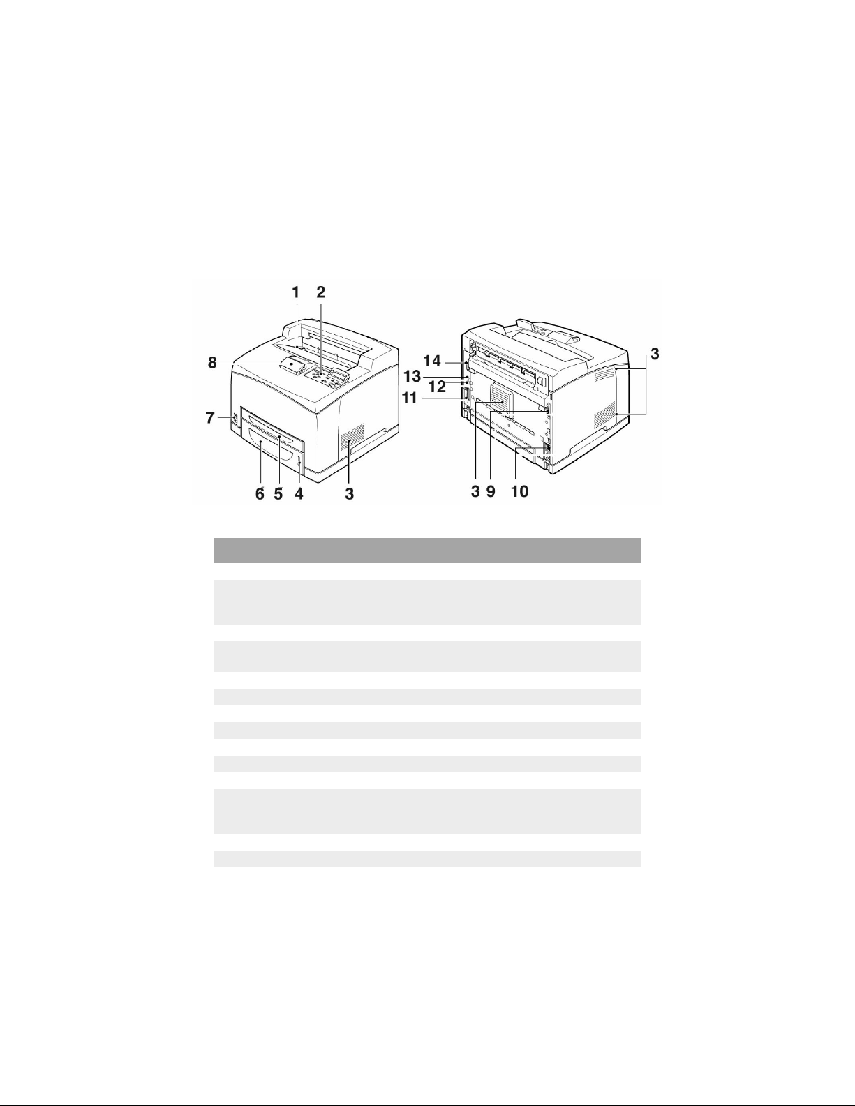
LOCATING PARTS OF THE PRINTER
The main parts of the printer and a bri ef des cription of th eir funct ions are
shown below:
No. Name Description
1 Center output tray Print jobs are output here with pri nte d side facing down.
2 Control panel Consists of the control buttons, indicators and display.
For control panel details, refer to “T he Control Panel and
Menu system” on page 43.
3 Ventilation slots Provide ventilation for t he i nt eri or of the printer.
4 Paper level indicator Indicates the level of the remaining paper in the 550 -sheet
5 Tray 1 Holds 150 sheets of paper.
6 Tray 2 H olds 250 sheets (B6200) or 550 sheets (B6300) of paper.
7 Power switch Switches the printe r powe r on and off.
8 Extension output tray Pull this tray out to print on paper larger than Letter.
9 Duplex unit connector For connecting the duplex unit (option).
10 Power cord connector For connecting the power cord.
11 Parallel connector For connecti ng a parallel cable.
12 Ne twork connector For connecting the network cable when using the printer as
13 USB connector For connecting a US B ca ble.
14 Serial c onnector For connecting a serial cable.
paper tray.
a network printer. (The Network Software Kit option needs
to have been installed to enable networking capability.)
INSTALLATION AND RELOCATION PROCEDURE > 11
Page 12
PREPARING A LOCATION FOR THE PRINTER
Place the machine on a level and sturdy surface that can withstand the
machine weight – 20.4 kg (45lb) (B6200) or 22.6 kg (50lb) (B6300). If
tilted, the machine may fall over and cause injuries.
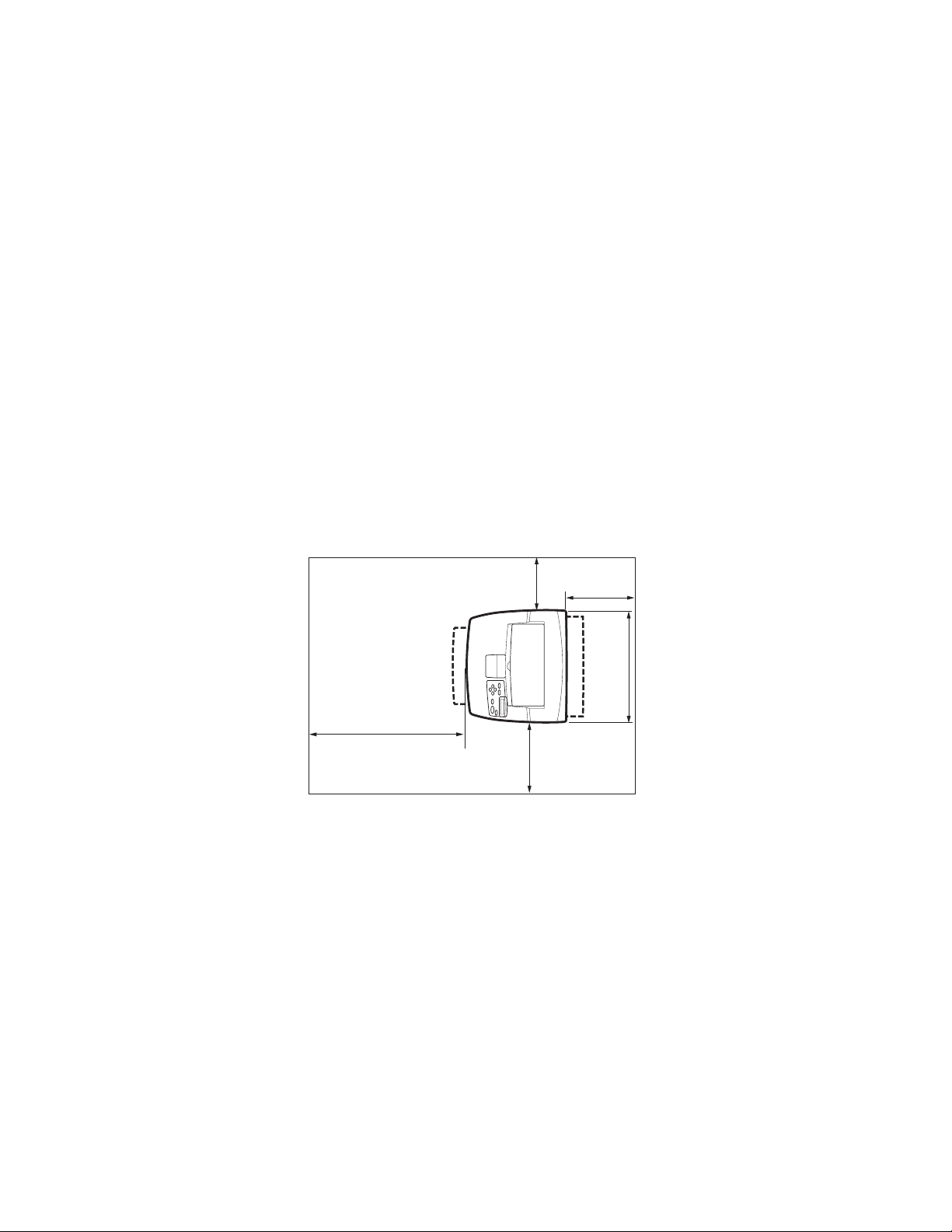
SPACE REQUIREMENTS
The printer has ventilation holes on the side and rear panels. Ensure that
the printer is installed with a minimum clearance of 255mm (10in) from
the rear vent to any wall, 200mm (8in) from the left vent to any wall, and
300mm (12in) from the right vent to any wall. A poorly ventilated
machine can cause excessive internal heat and fire. The following
diagram shows the minimum clearances required for normal operation,
consumables replacement, and maintenance to ensure your machine
operates at peak performance.
200 mm
8’’
402 mm
16”
* B6200
255 mm
10”
300 mm
12”
ENVIRONMENT
Ensure that the installation location meets the following conditions:
• Do not place the printer in a hot, humid, dusty or poorly ventilated
environment. Prolonged exposure to such adverse conditions can
result in fire or electric shock.
12 > INSTALLATION AND RELOCATION PROCEDURE
Page 13

• Temperature range 10 – 32 °C (50 – 89 °F), humidity range 15 –
85% (no condensation). Humidity should be 70% or below at 32
°C (89 °F), and temperature should be 28°C (82 °F) or below at
85% humidity.
NOTE
Sudden temperature fluctuations can affect pr int quality. Rapi d heating o f
a cold room or moving the printer from a location with low humidity/
temperature to high humidity/temperature can cause condensation inside
the printer, directly interfering with image transfer. When condensation
occurs, leave the printer for at least 1 hour to acclimatize to the
environment before using it.
• Do not expose the printer to direct sunlight.
• Do not expose the printer to the direct draft of air-conditioning or
heating.
INSTALLATION AND RELOCATION PROCEDURE > 13
Page 14
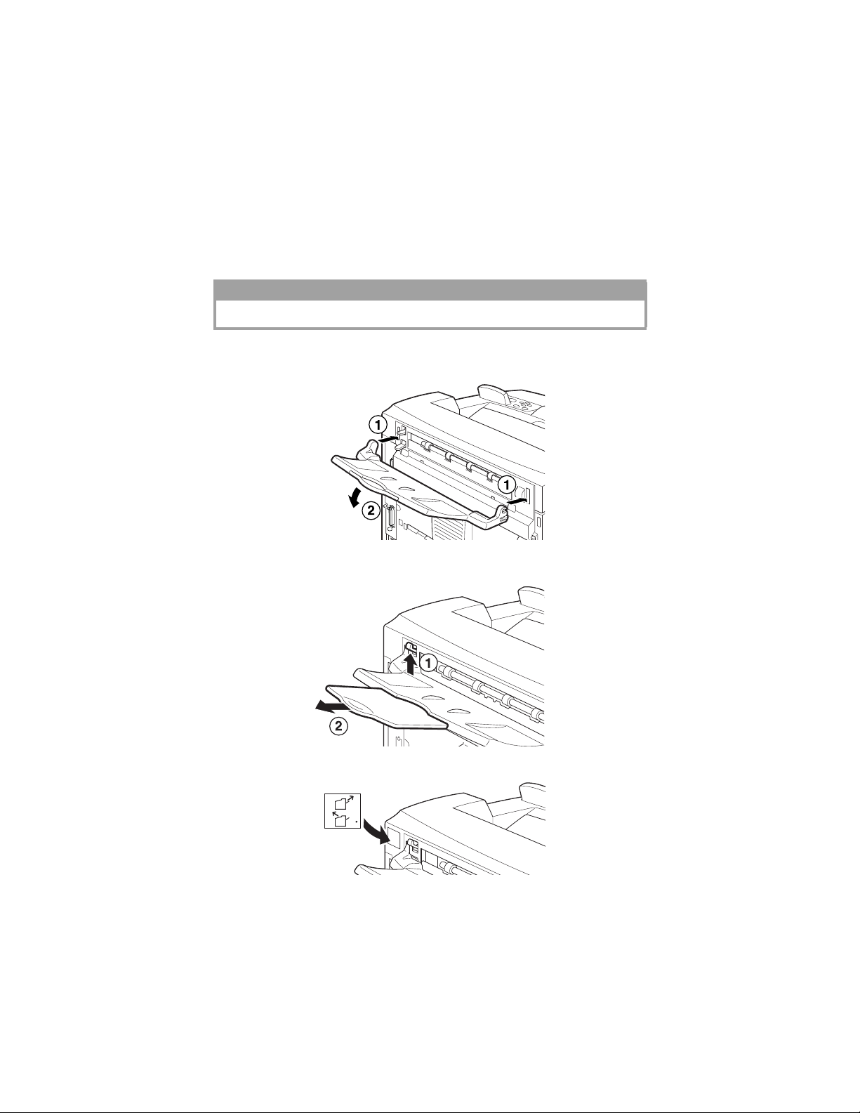
INSTALLING THE FACE UP (REAR) TRAY
You can install the face up (rear) tray on this printer if required.
NOTE
A face up (rear) tray can be installed on the B6300 only.
1. Insert the right and left tabs of the face up (rear) tray in to the holes
at the back of the printer (1), and lower the tray into position (2).
2. Push up the rear output tray lever as shown in the diagram (1) and
pull out the extension tray (2).
3. Affix the label provided to the back of the printer.
14 > INSTALLATION AND RELOCATION PROCEDURE
Page 15

INSTALLING THE OPTIONAL ACCES SORIES
If you have purchased any optional accessories, install them before setting
the drum-toner cartridge and before l oading paper. If there are no optional
accessories to install, proceed to the next section, “Installing the Drum-
Toner Cartridge” on page 35.
WARNING!
Never open or remove machine covers that are secured with screws unless
specifically instructed in this guide. A high voltage component can cause
electric shock.
Do not try to alter the machine configuration, or modify any parts. An
unauthorized modification can cause smoke or fire.
CAUTION!
Ensure the printer is switched off b e for e conn ecting an y inter face cables or
options. Connecting cables or options to a live machine may result in an
electric shock.
NOTE
To add more optional accessories when the printer is in use, you need to
change the configuration of optional accessories in the printer driver. For
details, refer to the Online Help for the printer driver.
INSTALLATION AND RELOCATION PROCEDURE > 15
Page 16
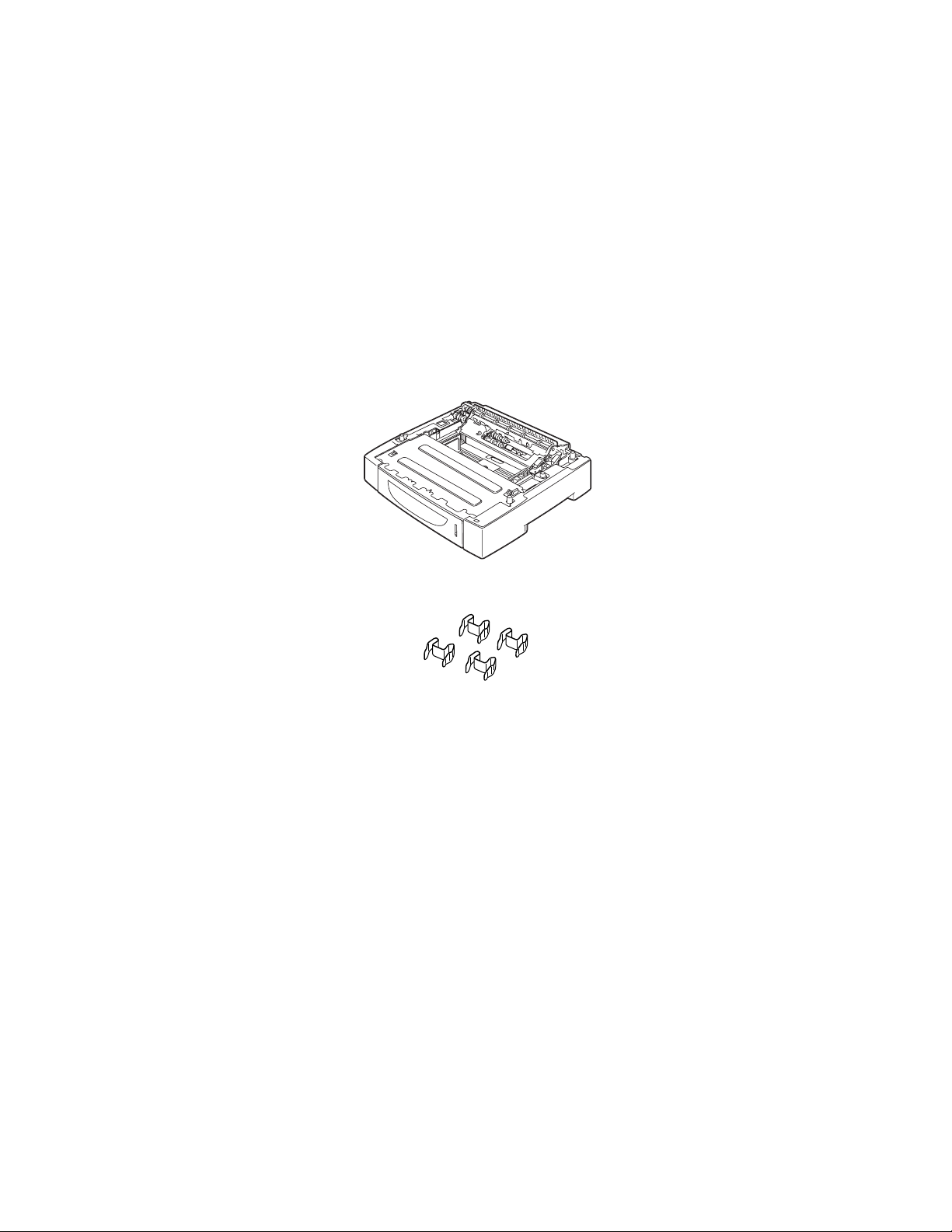
INSTALLING A UNIVERSAL TRAY
You can install up to two l evels of universal tray (550-sheet) op tion to this
printer.
This section explains how to install two trays as an example.
1. Ensure that you have all of the following items:
• Tray module and paper tray
• Fasteners (four pieces)
16 > INSTALLATION AND RELOCATION PROCEDURE
Page 17
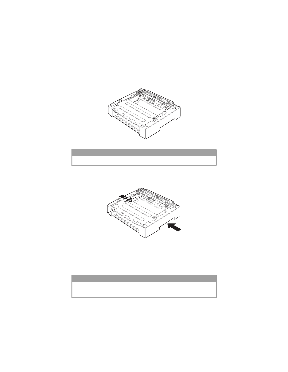
2. Place the tray module to be installed at the bottom level on a flat
surface, then pull out the paper tray.
NOTE
Proceed to step 6 if you are installing only one tray module.
3. Lift the tray module to be installed at the top level by holding the
parts as shown in the diagram.
4. Align the front and back corners of the top and bottom tray
modules, and slowly lower the top module so that the guide pins
at the four corners of the bottom module fit into the holes at the
base plate of the top module.
CAUTION!
The tray module must be lowered gently. Otherwise, the interior parts may
be damaged.
INSTALLATION AND RELOCATION PROCEDURE > 17
Page 18
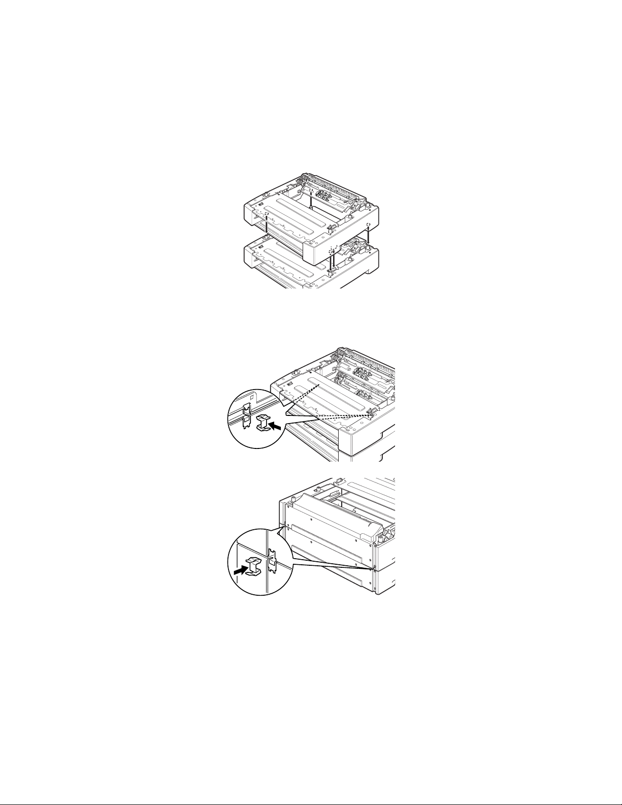
5. Insert the fasteners provided into the two locations inside the tray
module and the two locations at the back of the tray module.
Insert the fasteners securely.
18 > INSTALLATION AND RELOCATION PROCEDURE
Page 19
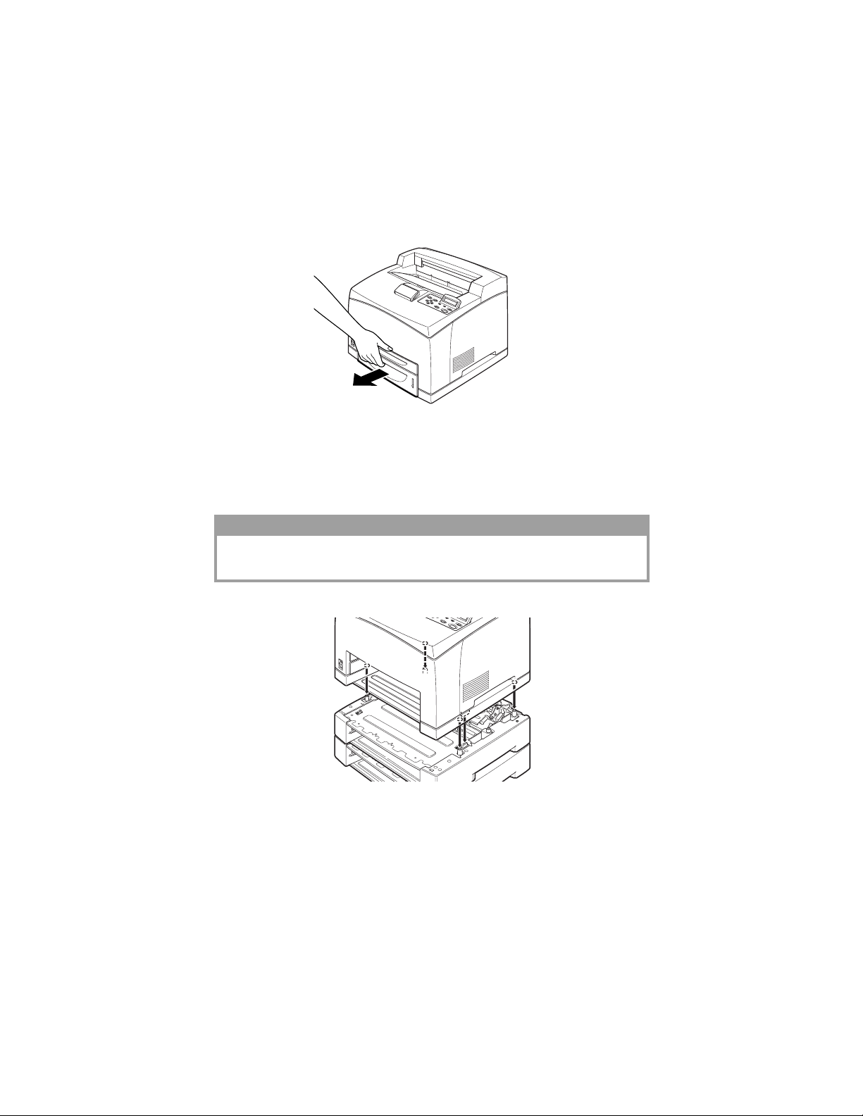
6. Pull the paper trays out of the printer.
7. Lift up the printer by holding the recessed areas.
8. Align the corners of the printer and the tray modules, and lower
the printer gently so that the guide pins at the four corners of the
tray modules fit into the holes at the base plate of the printer.
CAUTION!
The printer must be lowered gently. Otherwise, interior parts of the tray
modules may be damaged.
INSTALLATION AND RELOCATION PROCEDURE > 19
Page 20

9. Insert the fasteners provided into the two locations inside and the
two locations at the back of the printer. Insert the fasteners
securely.
10. Push both trays completely into the printer.
NOTE
For details on how to load paper, refer to “Loading paper” on page 40.
20 > INSTALLATION AND RELOCATION PROCEDURE
Page 21

INSTALLING THE DUPLEX UNIT
You can install a duplex unit option on this printer. If a face up tray has
been fitted, remove it by reversing the steps in “Installing the Face Up
(Rear) Tray” on page 14 before installing the duplex unit and re fit it when
the duplex unit has been installed.
1. Remove the duplex unit cover by pushing the two tabs as shown
in the diagram (1).
Next, remove the connector cap at the top right of the back of the
printer (2).
2. Insert the right and left tabs at the bottom of the duplex unit into
the holes at the back of the printer, and then align the top part of
the duplex unit with the printer.
Ensure that the connector of the duplex unit is connected to the
connector of the printer.
INSTALLATION AND RELOCATION PROCEDURE > 21
Page 22

3. Tighten the screws at both ends of the bottom of the duplex unit.
22 > INSTALLATION AND RELOCATION PROCEDURE
Page 23

INSTALLING THE OFFSET CATCH TRAY
You can install an offset catch tray option on this printer.
NOTE
An offset catch tray can be installed on the B6300 only.
1. Lift the second lever on the top left corner at the back of the
printer (1), and open the cover (2).
NOTE
When the duplex unit is installed, lift the lever on top of the left side cover
of the unit and open the unit, then open the cover as shown in the diagr am.
INSTALLATION AND RELOCATION PROCEDURE > 23
Page 24

2. Loosen the right and le ft thumb screws as sho wn in the diagr am to
uninstall the top cover of the paper exit.
3. Insert the right and left tabs of the offset catch tray into the holes
at the top of the printer (1) and lower it slowly onto the top of the
printer (2).
4. Secure the screws at both ends of the bottom of the offset catch
tray.
24 > INSTALLATION AND RELOCATION PROCEDURE
Page 25

5. Close the cover.
6. If you install the face up (rear) tray on the printer, affix the label
provided to the back of the offset catch tray.
7. Pull out the extension tray.
CAUTION!
Printing while the tray is fo l ded up m a y cau se a paper jam. Be sure to open
the tray when using the printer.
8. Flip up the stopper when printing on heavy weight papers.
INSTALLATION AND RELOCATION PROCEDURE > 25
Page 26

INSTALLING A NETWORK SOFTWARE KIT, HARD
DISK, COMPACT FLASH DISK, OR ADDITIONAL
MEMORY
The same steps are required at the beginning and at the end of each
installation to prepare the printer and to close it. These steps ar e described
here.
Preparing the printer
1. Remove the screw on the right detachable cover.
2. Slide the cover towards the back of the printer (1) to release the
protrusions at the bottom and pull it downwards (2).
26 > INSTALLATION AND RELOCATION PROCEDURE
Page 27

3. Remove the two screws on top of the metal cover (1), and pull the
metal cover upwards (2).
Closing the printer
1. Align and insert the protrusion at the bottom of the metal cover
into the notch of the printer (1), and tighten the two screws on the
top of the cover (2).
2. Align and insert the protrusions at the top of the right detachable
cover into the notches of the printer (1). Fit the protrusions at the
bottom of the cover into the printer (2) and slide the cover towards
the front of the printer (3).
3. Tighten the screw on the right detachable cover.
INSTALLATION AND RELOCATION PROCEDURE > 27
Page 28

INSTALLING A NETWORK SOFTWARE KIT
You can install a network software kit option on this printer. Installing this
option may initialize the settings of [Network/Port] and [Allocate
Memory].
CAUTION!
Never touch the connectors of the network software kit.
Never allow the network software kit to be bent or damaged.
Before handling the network software kit, touch something metal in order
to discharge any electrostatic charge built up in your body.
1. Refer to “Preparing the printer” on page 26.
2. Hold the network software kit so its notch (1) is aligned with the
protrusion on the slot.
3. Release the hook on the top of the slot.
4. Gently insert the network software kit into the slot, and press
firmly at the top corner of the card then at the bottom corner.
28 > INSTALLATION AND RELOCATION PROCEDURE
Page 29

Inserting the network software kit fully and securely into the slot
will cause the hook on the top of the slot to rise.
NOTE
Be sure to insert the network software kit securely into the slot as far as it
will go.
5. Remove the cap from the network connector.
6. Refer to “Closing the printer” on page 27.
INSTALLATION AND RELOCATION PROCEDURE > 29
Page 30

INSTALLING A HARD DISK
You can install a hard disk option on this printer.
NOTE
> When the Compact Flash disk (option) is installed on your printer, you
cannot install the hard disk. You can install only one of them.
> Installing this option may initialize the settings of [Network/Po rt ] and
Allocate Memory].
CAUTION!
The hard disk is a delicate item and must be handled with care. In the event
that damage does occur , it may erase i mpor ta nt dat a saved on the dis k. It is
recommended that you back up your data regularly.
1. Refer to “Preparing the printer” on page 26.
2. Remove the screws on the right and left sides of the Compact
Flash bracket (1) and remove the Compact Flash disk drive as
shown in the diagram (2).
3. Remove the cable of the Compact Flash bracket from the
connector on the printer.
30 > INSTALLATION AND RELOCATION PROCEDURE
Page 31

4. Connect the cable of the hard disk to the connector on the printer
as shown in the diagram.
CAUTION!
When connecting the cable, hold the disk firmly by hand to prevent it from
dropping.
5. Hold the hard disk as shown in the diagram, and install it in the
printer. Align the arrow on the hard disk with the arrow on the
printer, and insert the bracket at the top of the disk into the install
position.
6. Tighten the screws on both sides of the hard disk.
7. Refer to “Closing the printer” on page 27.
INSTALLATION AND RELOCATION PROCEDURE > 31
Page 32

INSTALLING A COMPACT FLASH DISK
You can install a Compact Flash disk option (only available in certain
regions) to this printer.
NOTE
> When the hard disk (option) is installed on your printer, you cannot
install the Compact Flash disk. You can install only one of them.
> Installing a Compact Flash disk erases any data that resides in the
Compact Flash disk.
> Installing this option may initialize all the printer settings for allocating
memory.
1. Refer to “Preparing the printer” on page 26.
2. Open the fastener on the Compact Flash disk drive.
3. Locate the Compact Flash disk as shown in the diagram.
32 > INSTALLATION AND RELOCATION PROCEDURE
Page 33

4. Close the fastener.
5. Refer to “Closing the printer” on page 27.
INSTALLATION AND RELOCATION PROCEDURE > 33
Page 34

INSTALLING ADDITIONAL MEMORY
The additional memory module for this printer is 512MB.
CAUTION!
Do not touch the terminal area of the additional memory.
Do not bend or damage the additional memory.
Before handling the memory board, touch something metal in order to
discharge any electrostatic charge built up in your body.
T o add more memory when the printer is in use, y ou need to con figure the
memory capacity in the printer driver. For details, refer to the Online Help
for the printer driver.
1. Refer to “Preparing the printer” on page 26.
2. Hold the additional memory so that the notch (1) is aligned with
the protrusion on the slot.
3. Insert the additional memory at an angle (1) and push it into the
printer until it clicks into position (2).
NOTE
Ensure that the additional memory is firmly inserted.
4. Refer to “Closing the printer” on page 27.
34 > INSTALLATION AND RELOCATION PROCEDURE
Page 35

INSTALLING THE DRUM-TONER CARTRIDGE
NOTE
Your printer is supplied with a drum-toner cartridge with capacity 6,000
Letter pages at 5% coverage. Replacement drum-toner cartridges are
available with capacity 10,000 pages (B6200/B6300) or 17,000 pages
(B6300 only).
When handling the drum-toner cartridge, take note of the following
points:
WARNING!
Never throw a drum-toner cartridge into an open flame as it can cause an
explosion.
• Do not subject the drum-toner cartridge to direct sunlight or
strong light.
• When installing the drum-toner cartridge, select a location not
subject to strong light and try to finish the installation within
5minutes.
• Do not touch the surface of the photosensitive drum. Do not let
the drum-toner cartridge stand upside down or place it upside
down as this may damage the drum.
• A drum shutter protects the photosensitive drum from light. Do
not open the drum shutter.
• Although the toner is not harmful to the body, wash it off
immediately with cold water if your hands or clothes are in
contact with it.
INSTALLATION AND RELOCATION PROCEDURE > 35
Page 36

• It is recommended to use up the drum-toner cartridge within one
year of removing it from its packaging.
• Keep the drum-toner cartridge out of the reach of children.
1. Open the cover.
NOTE
When the optional offset catch tray is installed, fold the tray first before
opening the cover.
WARNING!
Do not touch any parts inside the printer.
2. T a ke the dr um-to ner cartri dge out of th e packagi ng box an d shake
it seven or eight times as shown in the diagram.
36 > INSTALLATION AND RELOCATION PROCEDURE
Page 37

3. Place the drum-toner cartridge on a flat surface and pull out the
seal horizontally.
CAUTION!
When pulling out the seal, pull it out horizontally. The tape might break if it
is pulled out diagonally.
After the seal has been pulled out, do not shake or bump the drum-toner
cartridge.
4. Hold the drum-toner cartridge by the grip and insert it into the slot
inside the printer.
CAUTION!
Do not touch any parts inside the printer.
Ensure that the drum-toner cartridge is firmly located.
5. Close the cover securely.
NOTE
If the offset catch tray is folded as in Step 1, close the cover an d then retur n
the tray to its original position.
INSTALLATION AND RELOCATION PROCEDURE > 37
Page 38

CONNECTING AN INTERFACE CABLE
Connect the interface cable to be used to the printer.
NOTE
Connect a USB cable only after the printer driver has been installed on the
computer.
1. Connect the interface cable to the interface connector at the back
of the printer: serial (1), USB (2), network (3), parallel (4).
For a parallel cable, lift up the wire clip on both sides to secure it
after it has been inserted into the connector.
2. For Parallel, USB, or Serial cables, connect the other end of the
cable to the interface connector of the computer.
38 > INSTALLATION AND RELOCATION PROCEDURE
Page 39

CONNECTING THE POWER CORD
When connecting the power cord, take heed of the information given in
“Safety precautions” on page 9.
1. Ensure that the
printer power switch
is in the <¡>
position.
2. Connect the power
cord to the power
cord connector at the
back of the printer.
Connect the other
end of the power
cord to the power
outlet.
3. Press the power
switch of the printer
to the < > position.
The power will be
applied and the
control panel will
display that the
printer is ready to
print.
NOTE
> If “Found New Hardware” displays on your screen, click Cancel.
> Depending on the network environmen t used, it may take some minutes
before the printer is ready for printing.
> If the message that the printer is ready to print but is unable to retrieve
an IP Address is displayed, continue operating as normal.
INSTALLATION AND RELOCATION PROCEDURE > 39
Page 40

LOADING PAPER
This section explains how to load Letter size plain paper in portrait
orientation in the paper tray.
Portrait
orientation
1. Place the paper tray on a flat surface and remove the lid.
2. If the base plate of the paper tray is raised, push it down.
40 > INSTALLATION AND RELOCATION PROCEDURE
Page 41

3. Squeeze the length guide and slide it to the desired paper s i ze (1).
Squeeze the right width guide and slide it to the desi red pap er size
(2).
4. Load the paper with the side to be printed facing up and with all
four corners aligned.
CAUTION!
Do not place paper over the right width guide.
Do not load paper exceeding the maximum fill line or the maximum
capacity allowed.
Align the right width guide with the paper width corr ectly . If the righ t width
guide is not in place, the paper will not be properly fed and this may cause
paper jams.
INSTALLATION AND RELOCATION PROCEDURE > 41
Page 42

5. Close the lid of the paper tray and push the tray completely into
the printer.
CAUTION!
The lid of the tray must be firmly closed. If not, the paper may become
misaligned.
6. Depending on the t ypes an d sizes o f the loaded paper, you need to
configure settings on the control panel.
Change the paper type when non-plain paper such as recycled
paper, heavyweight paper or transparencies is loaded.
Configure the paper size when custom size paper is loaded.
42 > INSTALLATION AND RELOCATION PROCEDURE
Page 43

THE CONTROL PANEL AND MENU SYSTEM
For full details on the control panel and menu structure, refer to the
Reference Guide.
The control panel components and their functions are described below:
12
354
6
89
7
No. Name Description
1 <MENU> button Press to display/close the menu screen.
2 <FEED/SELECT>
button
3 <READY> indicator When illuminated, the printer is ready to receive data from
4 LCD Display Displays menu values, printer status and error messages.
5 <ATTENTION>
indicator
6 <POWER SAVE>
button/indicator
7 <CANCEL> button Press to cancel printing.
8 <ON LINE> button Press to enter offline status, in which the printer cannot
Press to set the required menu value and use to print reports/
lists.
the computer.
When illuminated, there is a malfunction in the printer.
Press to enter/exit power save mode. The indicator is
illuminated when the printer is in power save mode.
receive data or process printing dat a. Press a gai n to exit
offline status and enter online status, in which the printer can
receive data from the comp uter.
INSTALLATION AND RELOCATION PROCEDURE > 43
Page 44

No. Name Description
9
<> <> <>
< > buttons
Press these to move to the required menu, item and required
value on the display. Also, press the < > button when you
are carrying out secure/sampled/delayed printing or when
you are checking/printing received mail ma nually.
Note: When you are changing the candidate values by the
< > < > buttons, you can press and hold down the
buttons to change the displ ay con ti nuously. Also, pressing
the < > < > buttons simultaneously displays the default
values.
NAVIGATING THE CONTROL PANEL MENUS
Display/Close the Menu
screen
Switch between the menu
levels
Switch between menus or
items in the same level
Move the cursor (_) of the
setting value to the right or left
Confirm setting <FEED/SELECT> button
<MENU> button
<>
button (moves one le vel downwards) or < > button
(moves one level upwards)
< > button (displays the previ ous m enu or item) or < >
button (displays the next m en u or it em )
< > button (mov es to the righ t) or < > but to n (m oves to
the left)
When you press the MENU button on the control panel, you enter the
printer’s menu system. At that point, the first line of the display contains
the text [Menu], indicating that you are in the menu system. The second
line of the display lists the active menu, which you can change by pressing
the < > or < > butto n.
Using these buttons repeatedly, you can cycle throu gh the m ain menus in
the following order: Print Language; Report/List; Meter Reading; Admin
Menu; Display Language.
By using the arrow button s as i n dicat ed ab ove, you can navigate throu gh
the menu system to make any required settings. For example, to set the
paper type in Tray 1 to accommodate recyc led paper, navigate as follows:
Admin Menu, Printer Settings, Paper Type, Tray 1, Recycled then press
the <FEED/SELECT> button to record the setting and the <MENU>
button to close the menu screen.
44 > INSTALLATION AND RELOCATION PROCEDURE
Page 45

SELECTING THE CONTROL PANEL LANGUAGE
English is the default langu age for all error and st atus messages; however,
these messages are also available in many languages. Use the following
procedure to change the display language.
NOTE
Refer to the section “The Control Panel and Menu system” on p age 43 for a
brief overview of the control panel and its menus and sub-menus.
1. Press the <MENU> button to display the Menu screen.
2. Press the < > or < > button until [Display Language] is
displayed, then press the < > button.
3. Press the < > or < > button until the required language is
displayed, then press the <FEED/SELECT> button.
4. Press the <MENU> button to complete the language setting.
INSTALLATION AND RELOCATION PROCEDURE > 45
Page 46

PRINTING A CONFIGURATION SUMMARY
To check whether the printer is correctly installed, use the control panel
to print the [System Settings List].
NOTE
If you have made a mistake when operating the control panel, press the
<MENU> button to restart. For details on how t o operate the control panel,
refer to “The Control Pa nel and Menu sy stem” on page 43.
1. Press the <MENU> button to display the Menu screen.
2. Press the < > or < > button u ntil [Report/List] is displayed,
then press the < > button.
3. Press the < > or < > button u ntil [System Settings] is
displayed, then press the < > button.
4. Press the <FEED/SELECT> button.
The [System Settings List] will be printed.
5. Press the <MENU> button when printing has completed.
NOTE
> The layout of the [System Settings List] may differ depending on the
configuration and settings of the printer.
> For B6300, [Rear Output Tray] is displayed in the column for Output
Device even when the rear tray is not installed.
> Reports/lists cannot be output to the face up (rear ) tr ay. When the face
up (rear) tray is installed, lower the face up (rear) tray output lever.
46 > INSTALLATION AND RELOCATION PROCEDURE
Page 47

SETTING PRINTER CONFIGURATIONS VIA A
WEB PAGE
If you are working in a TCP/IP-enabled environment, you can use a web
browser to display the printer or job printing status and to change the
settings.
Among the printer settings that are made on the control panel, settings for
the system and network ports can be configured under [Printer],
[Network] and Maintenance] on the web page.
NOTE
> The web page facility is only available when the printer is connected to
the network.
> Refer to the Reference Guide when the web page does not appear after
carrying out the steps 1 and 2 below.
> You can also use Telnet to set the printer configuration. For details on
the settings, refer to the NIC Configuration Guide.
1. Boot your computer, and start the web browser.
2. Enter the printer’s IP address or URL in the address input column
on the web browser and press the <Enter> key.
Using Online Help
For details regarding the items that can be set in each screen, click the
[Help] button to display the Online Help.
INSTALLATION AND RELOCATION PROCEDURE > 47
Page 48

INSTALLING THE PRINTER DRIVER
To print from the computer, install the printer driver and other required
software.
The installation procedure(s) you will use for your p rinter vary according
to operating system, usage of the USB port, and network connection.
Instructions for installing drivers on Windows and Macintosh operating
systems are given below. Solaris, Linux and HP-UX are dealt with in
other parts of your documentation.
MICROSOFT WINDOWS SYSTEMS
NOTE
For network installation information, see the Network User Guide on the
CD-ROM. Click the Documentation/Network User’s Guide buttons.
INSTALL THE PCL6 EMULATION DRIVER
1. Make sure the cable is connected t o you r pri n te r and PC and your
printer is turned OFF.
2. Insert the driver CD supplied with your printer into your CDROM drive. The CD will autorun. (If it doesn’t, click Start →
Run → Browse. Browse to your CD-ROM drive and doubl eclick Install.exe, click OK.)
3. The License Agreement appears. Click Next.
4. If prompted, select your language.
5. The Software Installation screen appears. Click the Printer
Driver Installer button.
6. Click Local printer. Click Next.
7.
Select the port you are using (
8. Select your printer model and PCL6 emulation type (the default
setting). Click Next.
9. If prompted, type a printer name for your printer. Click Next.
10. If prompted, select “do not share this printer” Click Next.
48 > INSTALLATION AND RELOCATION PROCEDURE
USB
or
LPT1 Parallel
). Click
Next
.
Page 49

11. Drivers are copied. Click Finish. If Connect cable screen
displays. Click Finish.
12. Switch your printer ON.
If the New Hardware Found Wizard displays:
13. Win 98: select “Search for the best driver for your device”, select
CD-ROM drive, clear other choices. Click Next twice.
Win XP and Win Me: select “Automatic Search for a better
driver.” Click Next.
14. The driver installs. Click Finish.
PRINT A TEST PAGE
1. From the taskbar, click Start→Settings→Printers (& Faxes).
2. Right-click the printer icon, then click Properties.
3. Click the Print Test Page button.
TO INSTALL THE POSTSCRIPT DRIVER AS WELL
1. With the Software Installation screen open, click the Printer
Driver Installer button.
2. Click Local printer. Click Next.
3. Select the LPT1 port. Click Next. USB Users: select the LPT1
port temporarily.
4. Select your printer model and PS emulation. Click Next.
5. Follow the on-screen instructions. Click Finish.
USB Users:
6. From the taskbar, click Start → Settings → Printers (& Faxes).
7. Right click the PS printer icon, then click Properties.
8. Click on the Details/Ports tab.
9. Select the USB port in the “Print to the following port”
drop-down list.
10. Click Apply, OK. Close the Printers dialog box.
INSTALLATION AND RELOCATION PROCEDURE > 49
Page 50

INSTALL PRINTER SOFTWARE UTILITIES
With the Software Installation screen open, click the Software Utilities
button. Select and install the utilities you want following the on-screen
instructions.
To access the utility program from your desktop, click
Start → Programs → OkiData.
ACTIVATE THE DUPLEX UNIT, INTERNAL HARD DRIVE
AND ADDITIONAL OPTIONS
If your printer has an optional duplex unit, internal hard drive, compact
flash disk, additional memory, universal paper tray, or face-up rear tray
and offset catch tray ( B6300 only) installed, yo u must enter the driver an d
activate them.
1. From the taskbar, click Start → Settings → Printers.
2. Right click the printer icon, then click Properties.
3. Select the Options/Device Settings tab.
4. Select the installed option.
5. Change setting to AVAILABLE.
6. Click Apply, OK.
NOTE
If you are installing both the PCL6 and PostScript drivers, you mu st activate
the installed options in both drivers. For more information, see the
Reference Guide contained on the CD-ROM supplied with your printer.
TO LOAD THE MANUALS
Note: In order to open the on- line manual, you must h ave Acrobat Reader
installed.
1. Insert the CD into your CD-ROM drive.
2. When the Software Installation screen appears, click the
Documentation button. Then click the button for the manual you
want to load.
50 > INSTALLATION AND RELOCATION PROCEDURE
Page 51

MACINTOSH - OS 9.1+
INSTALL THE DRIVER
1. Turn on the printer, then turn on the computer.
2. Place the Drivers CD supplied with your printer into the
CD-ROM drive.
3. Double-click the CD icon that appears on the desktop.
4. Open the MAC folder.
5. Open the PSDRV folder.
6. Open your language folder.
7. Double-click the OKI MAC Installer icon, then click Continue
and accept the License agreement.
8. Select Classic Easy Install from the drop-down menu. Click
Install.
9. Select your printer model. Click OK.
10. When the installation is complete, click Quit.
CREATE THE DESKTOP PRINTER FOR A NETWORK
1. Activate Chooser from the Apple menu.
2. Select the LaserWriter8 icon and highlight the printer model.
3. Click Create. The printer icon appears on the desktop.
4. Close Chooser.
CREATE THE DESKTOP PRINTER FOR USB
1. Navigate to your local hard drive → Application (Mac OS 9) →
Utilities.
2. Double-click the Desktop Printer Utility icon.
3. Highlight Printer (USB).
4. In the drop-down box, select LaserWriter 8. Click OK.
5. Under PostScript Printer Description (PPD) file, click Change.
INSTALLATION AND RELOCATION PROCEDURE > 51
Page 52

6. Make sure the Printer Descriptions folder is selected in the
drop-down box.
7. Highlight your printer model, click Select.
8. Under USB Printer Selection, click Change.
9. Highlight your printer model, click OK.
10. Click Create. The printer icon appears on the desktop.
11. Click Save.
ACTIVATE THE DUPLEX UNIT AND ADDITIONAL OPTIONS
1. Highlight the printer created on the desktop.
2. Select Printer from the desktop menu.
3. Click the Change drop-down menu.
4. Select each option. Click the To drop-down menu and select
Installed. Click OK.
TO PRINT A JOB USING THE OPTIONAL DUPLEX UNIT
1. Select File from the desktop menu.
2. Click Print Desktop from the drop-down menu.
3. Select Layout.
4. Check Print on Both Sides. Click Print.
TO LOAD THE MANUALS
Note: In order to open the on-line manual, you must have Acrobat Reader
installed.
1. Insert the CD into your CD-ROM drive.
2. From the CD contents folder, either open the file directly or drag
the Manual folder to copy them to the desktop.
52 > INSTALLATION AND RELOCATION PROCEDURE
Page 53

MACINTOSH - OS X.1+
INSTALL THE DRIVER
Note: Be sure to switch off antivirus softw ar e befo re installing a printer
driver.
1. Turn on the printer, then turn on the computer.
2. Place the Drivers CD supplied with the printer in the CD-ROM
drive.
3. Double-click the CD icon that appears on the desktop.
4. Open the MAC folder.
5. Double-click PSDRV.
6. Double-click your language.
7. Double-click the OKI Mac Installer icon, then click Continue
and accept the License agreement.
8. Select MAC OS X.1+ Driver from the drop-down menu in the
left corner. Click Install.
9. Select your printer model. Click OK.
10. When the installation is complete, click Quit.
ADDING THE PRINTER FOR USB
1. Run the Print Center (Local HD → Applications → Utilities →
Print Center).
2. Click Printers from the menu bar.
3. Click Add Printer.
4. Select USB from the drop down menu.
5. Highlight your printer model from the product list.
6. Under the Printer Models drop down list, select Oki.
7. Select your printer model. Click Add.
8. Close the Print Center.
INSTALLATION AND RELOCATION PROCEDURE > 53
Page 54

ADDING THE PRINTER FOR A NETWORK
1. Run the Print Center (Local HD → Applications → Utilities →
Print Center).
2. Click Printers from the menu bar.
3. Click Add Printer.
4. Select Appletalk from the drop down menu.
5. Select your printer model (see Note).
6. Click Add.
NOTE
To list printer models, enable EtherTalk in the printer control panel:
1. Press the <MENU> button to display the Menu screen.
2. Press < > button until [Admin Menu] displays.
3. Press < > button until [Network/Port/Paralle l] disp lays.
4. Press until [EtherTalk] displays.
5. Press until [Port Status/Disable] displays.
6. Press until [Enable] displays.
7. Press the <FEED/SELECT> button to set Enable.
8. Press the <MENU> button to complete the setting.
ACTIVATE THE DUPLEX UNIT AND ADDITIONAL OPTIONS
1. In the Print Center, highlight your printer model.
2. Click Printers from the Menu bar.
3. Select Show Info.
4. Select Installable Options from the drop-down list.
5. Select your printer’s installed options.
54 > INSTALLATION AND RELOCATION PROCEDURE
Page 55

6. Click Apply Changes.
7. Close the Print Center. Your printer is available under Mac OS
X.1 applications.
TO PRINT A JOB USING THE OPTIONAL DUPLEX UNIT
1. From your application, click File → Print → Copies & Pages →
Duplex.
2. Check Print on Both Sides.
3. Select the binding.
4. Click Print.
TO LOAD THE MANUALS
Note: In order to open the on-line manual, you must have A crobat Reader
installed.
1. Insert the CD into your CD-ROM drive.
2. From the CD contents folder, either open the file directly or drag
the Manual folder to copy them to the desktop.
PRINTING A TEST DOCUMENT
After completing the installation procedure, verify that the printer is
working correctly by printing a document from an application.
INSTALLATION AND RELOCATION PROCEDURE > 55
Page 56

IF PAPER JAMS
CAUTION!
When removing jammed paper , make sure th at no pieces of torn paper are
left in the machine. A piece of p aper remaining in the machine can cause a
fire. If a sheet of paper is wrapped around the heat roller , or when clearing
a jammed paper that is difficult or impossible to see, do not try to remove
it by yourself. Doing so may cause injuries or burns. Switch off the
machine immediately, and contact your Oki dealer.
Guided by the message on the control panel, open the cover and remove
the jammed paper. If paper is torn, check f or any remaining torn pieces o f
paper.
CAUTION!
The fuser unit gets hot when operating. Avoid touching it.
The covers and trays are identified in the following diagram:
Cover A: When the optional offset catch tray is installed, fold the tray first
before opening cover A. When a message to remove the drum-toner
cartridge is displayed, refer to “Inside Cover A ” on page 58.
56 > IF PAPER JAMS
Page 57

Cover B:
NOTE
Remove the rear tray (if installed) when opening the back cover.
Open Cover B (For B6300, raise the lever as shown in the diagram and
open cover B (1)). After opening cover B, hold the part marked with a *,
open the cover of the fuser unit (2) and remove any jammed paper.
Cover C (Duplex Unit):
NOTE
Remove the rear tray (if installed) when opening the back cover.
Push up the lever (1) to open the duplex unit cover.
IF PAPER JAMS > 57
Page 58

Cover D Offset catch tray:
Paper Tray: Pull out the tray and follow the procedure to remove paper.
Refer to “Inside the Paper Tray” on page 59.
INSIDE COVER A
Follow the procedure below to remove any jammed paper when the
control panel indicates either [Paper jam Open Cover A] or [Remove
cartridge Clear jam]:
1. Open cover A, and holding the drum-toner cartridge by the grip,
remove it from the printer (1).
2. Turn the roller as shown in the diagram and remove any jammed
paper inside (2).
58 > IF PAPER JAMS
Page 59

3. Return the drum-toner cartridge and Cover A to their original
positions.
CAUTION!
When the optional offset catch tray is installed, close Cover A first before
returning the tray to its original position.
If you continue to print with the offset catch tray folded, this may cause a
paper jam. Always use the printer with the tray open.
INSIDE THE PAPER TRAY
Follow the procedure below to remove any jammed paper when the
following messages are displayed intermittently: [Pull out all trays. Clear
jam] and [Clear jam and close Cover A]:
Pulling out the paper trays:
1. Pull out all paper trays and remove any wrinkled paper.
2. Examine the inside of the printer and remove any jammed paper.
IF PAPER JAMS > 59
Page 60

After removing the paper:
1. Push the paper trays completely back into the printer.
2. Open and close Cover A to clear the error message.
60 > IF PAPER JAMS
Page 61

ERROR MESSAGES
If an error message is displayed at the control panel, follow the
instructions to f ix the error. De pending on the message content, follow the
instructions in the Reference column below to fix the error.
Message content Reference
An error code xxx-xxx is
displayed.
Paper jam or “Remove paper”
is displayed.
Installing and replacin g th e
drum-toner cartridge
Loading and replenishing
paper
The following section explains the contents and actions required for the
more complex messages. For details on messages n ot described here, refer
to the Reference Guide.
Message Condition/Reason/Action
Corrupt HDD File.
Press SEL key
Refer to the Reference guide for a list of error codes.
Refer to “If paper jams” on page 56.
Refer to procedures described on the consumables packaging
box or “Installin g the D rum-Toner Cartridge” on page 35.
Refer to “Loading pap er” on pa ge 40.
When the hard disk (option) is instal led, the prin ter assum es that data
in the hard disk is corrupted if power is cut off when the printer is in
use.
Press the <FEED/SELECT> button on the control panel. The hard disk
will be initialized.
Corrupt Log file
Press SEL key
Incorrect paper
type Reselect
SEL to print
CANCEL to cancel
Initializing the hard disk will delete data for registered forms, logos,
secure print, and PostScript downlo ad fo nts.
When the hard disk (option) is instal led, the prin ter assum es that data
in the hard disk is corrupted if power is cut off when the printer is in
use.
Press the <FEED/SELECT> button on the control panel. The log file
will be initialized.
It can take 1 minute to initial ize the log file. Do not switch off the
power of thi s printer whe n in itialisation is in progre s s .
Paper of the type specified unde r [Pa p er Type] in the printer driver is
not loaded in the trays. Press the <FEED/S ELECT> butt on on the
control panel to print on paper of another type or press <CANCEL> to
cancel the job.
ERROR MESSAGES > 61
Page 62

Message Condition/Reason/Action
Off-line
Off-line
Data in memory
Ready to prin t
DNS Update Fail
Ready to prin t
Get IP Add. Fail
Ready to prin t
Repl. Drum/Toner
The printer is o ff-line, probably because the <ON LINE> bu tton has
been pressed. To cancel the off-line status, press the <ON LINE>
button again.
The printer cann ot re cei ve any pr i nt dat a fro m th e compu ter whil e it is
off-line.
Unable to retrieve IP address from DNS.
Check the settings for DNS and retrieving IP address.
Failed to retrieve IP address from DHCP server.
Change the retrieving metho d for IP a ddre ss and manually set the IP
address.
Refer to the Reference Guide.
The drum/toner cartridge is almost used up. Prepare a new drum/toner
cartridge. You can still print about another 100 pages even when this
message is displayed.
62 > ERROR MESSAGES
Page 63

INDEX
A
arrow buttons.......................................44
C
Condensation Problems Occur............13
connecting interface cables .................38
Connecting power cord .......................39
E
Error Messages (control panel)...........61
F
<FEED/SELECT> button ...................44
I
Installing Additional Memory.............34
Installing the Drum/Toner Cartridge...35
Installing the Optional Accessories.....15
installing the printer............................12
Installing the Printer Driver.................48
L
loading paper
loading paper in paper tray..............40
Printer driver installation ....................48
printing reports/lists ............................46
S
system settings list ..............................46
W
Web page facility
Using Online Help...........................47
When Paper Jams................................56
Windows systems driver installation ..48
M
Macintosh OS X.1+ driver installation53
Macintosh OS 9.1+ driver installation 51
MENU button......................................44
Menu Items on the Control Panel........43
O
Online Help (Web page facility).........47
P
paper tray.............................................59
INDEX > 63
Page 64

LIMITED WARRANTY:
UNITED STATES AND CANADA
Oki Data Americas, Inc. (Oki Data) warrants this printer to be free from
defects in material and workmanship and will remedy any such defect
according to the terms of this Limited Warranty.
Oki Data will repair (or at its option, replace) at no charge, any defective
component(s) of the Printer for one (1) year from the date of purchase.
This Limited Warranty extends to the original purchaser only. This
Limited Warranty does not extend to consumable items.
ON-SITE REPAIR
Note: On-Site Repair is available in the United States and Canada
only. On-Site Repair does not include the replacement or repair of
product consumables or supplies.
Oki Data will, for a period of one (1) year from the date of original
purchase, repair or replace (at Oki Data's option) on-site at the
original purchaser's facility and without charge, any defective
component(s) of the printer, provided that the warranty service is
performed by an Oki Data authorized service provider. Oki Data
reserves the right to use new and/or refurbished parts in the
warranty repair process.
As a condition of this Limited Warranty, requests for On-Site
Repair must include the name and phone number of a fully
competent and responsible adult with the authority to consent to
the entry of the servicing technician to the premises where the
printer is located, and who will remain with the servicing
technician while the service work is performed. Any and all
dangerous conditions must be removed from the site prior to and
throughout the time a service technician is present. The service
technician may refrain from entering the premises or continuing to
provide services at any site, if in the servicing technician's
reasonable judgement the site poses a risk of physical harm or
danger. If warranty services cann ot be performed or completed d ue
to any of the foregoing reasons the On-Site service option is null
and void and the product must be returned to an authorized Oki
Data service location for warranty repair service.
64 > LIMITED WARRANTY: UNITED STATES AND CANADA
Page 65

To make request or claim for service under th is Limited Warrant y contact
your local Oki Data authorized service center or Oki Data at
1-800-OKI-DATA (1-800-654-3282).
A written receipt for the product, showing the date of purchase, dealer’s
name, and both the model and serial numbers of this printer must
accompany any request or claim for work to be performed under this
Limited Warranty.
This Limited Warranty shall not apply if the product has been damaged
due to abuse, misuse, misapplication, accident, or as a result of service o r
modification by any other than an authorized Oki Data service center.
THERE ARE NO EXPRESS WARRANTIES OTHER THAN THOSE
ON THE FACE HEREOF AND DESCRIBED ABOVE. NO
WARRANTIES WHETHER EXPRESS OR IMPLIED, INCLUDING,
BUT NOT LIMITED TO, ANY IMPLIED WARRANTIES OF
MERCHANTABILITY OR FITNESS FOR A PARTICULAR
PURPOSE, SHALL EXTEND BEYOND THE RESPECTIVE
WARRANTY PERIOD DESCRIBED ABOVE. Some states do not allow
limitations on how long an implied warranty lasts, so the above limitation
may not apply to you.
OKI DATA SHALL NOT BE RESPONSIBLE OR LIABLE FOR ANY
SPECIAL, INCIDENTAL OR CONSEQUENTIAL DAMAGES OR
LOSS ARISING FROM THE USE OF THIS PRODUCT. Some states do
not allow the exclusion or limitation of incidental or consequential
damages, so the above exclusion may not apply to you.
Additional informatio n on obtain ing service under this Li mited Warrant y
is available by contacting the Oki Data dealer from whom the product was
purchased, by contacting Oki Data directly at 1-800-654-3282
(1-800-OKI-DATA) [U.S. and Canada, English only] or at 1-856-2227496 (Spanish only), or by contacting the service location listed below.
This Limited Warranty applies to this printer. However, the procedure for
obtaining service may vary outside the continen tal United States. Contact
your Oki Data dealer for such warranty service information.
This warranty gives you specific legal righ ts, and you may also have other
rights which vary from state to state.
LIMITED WARRANTY: UNITED STATES AND CANADA > 65
Page 66

OKI DATA AMERICAS SERVICE
CENTERS
UNITED STATES
Oki Data Americas Inc.
2020 Bishops Gate Blvd.
Mt. Laurel, NJ 08054, USA
Tel: 1-800-654-3282
Fax: 1-856-222-5247
CANADA
Oki Data Americas Inc.
2735 Matheson Blvd. East, Unit 1
Mississauga, Ontario
Canada L4W 4M8
Tel: 1-800-654-3282
Fax: 1-905-238-4427
MEXICO
Oki Data de Mexico, S.A. de C.V.
Mariano Escobedo No. 748 - 8 Piso
Col. Anzures, e.p. 11590
México, DF
BRAZIL
Oki Data do Brasil, Ltda
Rua Alexandre Dumas, 2220 - 80
andar
Chácara Santo Antonio
04717-004, São P a ulo, SP Brasil
Tel: +(5511) 3444-3500
Fax: +(5511) 3444-3501
Support Center: 0800-11-55-77
e-mail: okidata@okidata.com.br
TECHNICAL SUPPORT
Oki Data Americas Inc.
2000 Bishops Gate Blvd.
Mt. Laurel, NJ 08054-4620, USA
Tel: 1-800-OKI-DATA
(1-800-654-3282)
Fax: 1-856-222-5320
http://www.okidata.com
Tel: +52 55 526 3-8 780
Fax: +52 55 5263-8785
66 > OKI DATA AMERICAS SERVICE CENTERS
59357801 Rev 1.1
 Loading...