

Page 1
MkI/MkII Automotive
TTX40/ TTX46MT
Owner’s Manual
Page 2
2
Safety Precautions
Note!
The shock absorber is a very important part of the vehicle and
will therefore affect the stability of the vehicle.
Read and make sure that you understand the information in
this manual and the mounting instructions before you use this
product. If you have any questions regarding installation or
maintenance please contact your nearest Öhlins dealer.
Öhlins Racing AB can not be held responsible for any
damage to the shock absorber, vehicle, other property or injury
to persons, if the instructions for installing and maintenance are
not followed exactly.
Warning!
This product was developed and designed exclusively for a
specific vehicle model and should only be installed on the
intended vehicle model in its original condition as delivered from
the vehicle manufacturer.
The specifications for the particular shock absorber are results
from tests run on a factory equipped vehicle. If wheel
dimensions, springs and/or other chassis parts have been
changed or modified, the clearances and vehicle stability can be
affected.
This product contains pressurized nitrogen gas (N2). Do not
open, service or modify this product without proper education
(authorized Öhlins dealer/distributor) and proper tools.
After installing this product, take a test drive at low speed to
make sure that your vehicle has maintained its stability.
If the suspension makes an abnormal noise, or the function is
irregular, or if you notice any leakage from the product, please
stop the vehicle immediately and return the product to an Öhlins
Service Centre.
Safety Symbols
In this manual, mounting instructions and
other technical documents, important
information concerning safety is
distinguished by the following symbols:
The Safety Alert Symbol means: Warning!
Your safety is involved.
Warning!
The Warning Symbol means: Failure to
follow warning instructions can result in
severe or fatal injury to anyone working with,
inspecting or using the shock absorber, or
to bystanders.
Caution!
The Caution Symbol means: Special
precautions must be taken to avoid damage
to the shock absorber.
Note!
The Note Symbol indicates information that
is important regarding procedures.
© Öhlins Racing AB. All rights reserved. Any
reprinting or unauthorized use without the written
permission of Öhlins Racing AB is prohibited.
Printed in Sweden.
Note!
When working on this product, always read your Vehicle Service
Manual.
This Manual should be considered a part of the product and
should therefore accompany the product throughout its life cycle.
1
Page 3
Page
Safety Precautions 1
1 - Introduction 3
2 - General description 4
3 - Damping force measurement 13
4 - Damping curve terminology 16
5 - External adjusters 17
6 - Limits in force and velocity 21
7 - Matching of damping force 21
8 - Hysteresis 22
9 - Cavitation 24
10 - Friction level 26
11 - Temperature stability 27
12 - Damper functions 28
13 - Damping guidelines 30
14 - Gas pressure 31
15 - Temperature range 31
Contents
16 - Routine maintenance 32
17 - Actions after a crash or re 33
18 - Valving reference program 34
19 - Damper conguration 35
20 - Damper dimensions 39
21 - Damper identication 54
22 - Technical data 54
23 - Optional parts 55
2
Page 4
4
1 - Introduction
Congratulations on choosing the Öhlins TTX40/ TTX46 MT damper,
the latest generation of twin tube dampers from Öhlins.
Get to know your TTX40/ TTX46 MT, and be sure to read this
manual thoroughly before using the dampers. We recommend that
you keep this manual handy.
The TTX40/ TTX46 MT damper is the culmination of three
decades of Öhlins’ successful participation in world championship
events winning more than 200 World Championships. Many
years of work together with some of the world’s most successful
racing teams together with advanced dynamic analysis methods
developed at Öhlins Racing headquarter in Sweden has given
Öhlins the unique knowledge needed to design the TTX40/ TTX46
MT damper.
The Öhlins TTX40/ TTX46 MT damper, originally developed for
formula racing, is designed to handle the demanding damping
characteristics needed for all types of tracks, from street courses to
super speedways. The TTX40/ TTX46 MT damper is fully adjustable
with maximised damper response together with qualities you’ve
never seen before when it comes to ”settings”.
Low and high speed compression and rebound damping are
externally adjustable and fully independent. The adjustment range
is huge with equal increments of force throughout the adjustment
range. Even the shape of the damping curve can easily be changed.
All adjusters affect the ow from the main piston, not the piston rod
displacement volume.
The compression damping forces of the TTX40/ TTX46 MT
damper are not, as in a conventional damper, caused by a pressure
drop on the rebound side, but by increased pressure on the
compression side. This reduces the risk of cavitation and makes
any reservoir valve or high gas pressure unnecessary. So, no
balancing of reservoir damping to main piston damping is needed
to avoid cavitation and improve damping response.
Maximum response and minimum risk of cavitation will always
occur. With no reservoir valve, the internal pressure of the damper
unit will be kept to a minimum.
The low amount of hysteresis results in excellent short stroke/high
force performance. Also, a very low gas pressure can be used
without any loss of damping performance.
Along with the damper comes a unique Valving Reference
Program (available for download free of charge at www.ohlins.com).
Make sure to choose the correct one for your damper (MkI/MkII).
This computer model of the damper will allow you to nd
damping curves without a dynamometer. It will reduce building time
tremendously and allow exact damper adjustments in pit lane. The
TTX40/ TTX46 MT product will revolutionise the work for mechanics
and engineers in the racing business.
This manual text is based on TTX40/ TTX46 MT dampers. These
are through rod type dampers loaded with several new concepts.
As always, all dampers are tested before they are delivered to the
customer. In keeping with Öhlins long tradition of perfection, quality
is outstanding and long life is to be expected.
Welcome to the World of Öhlins.
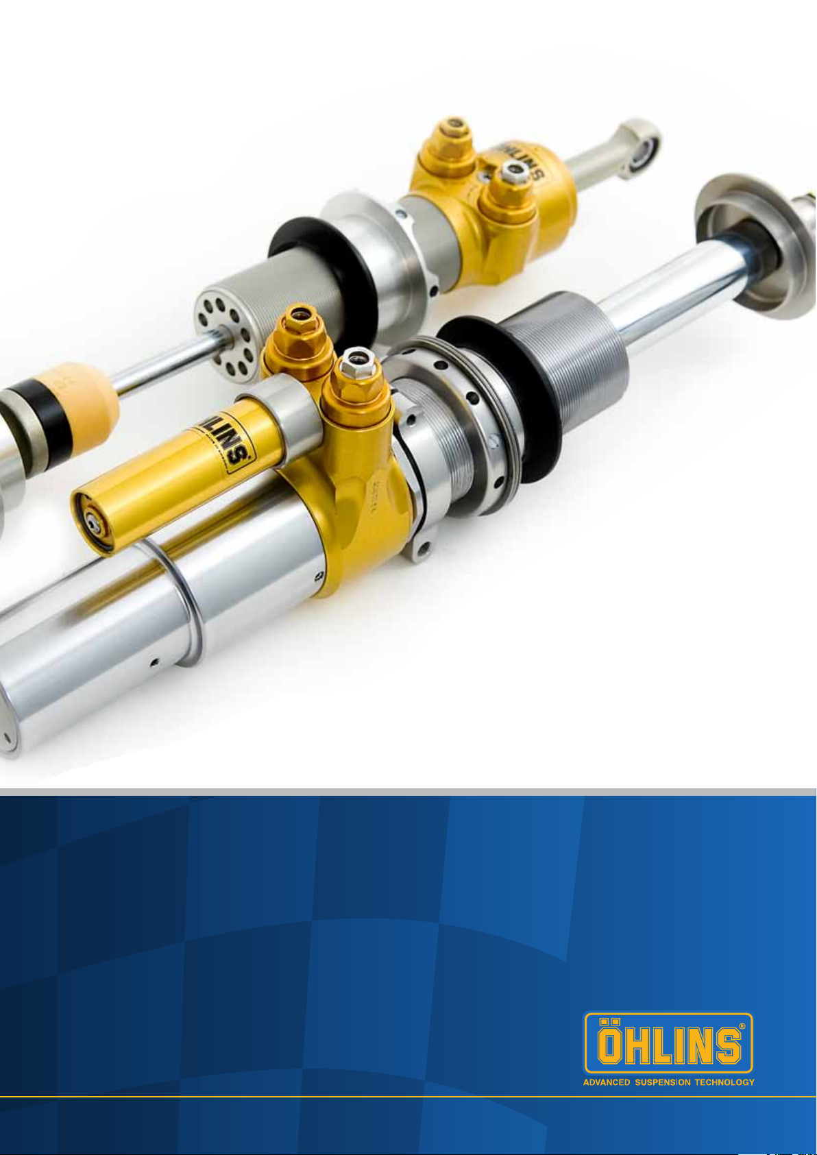
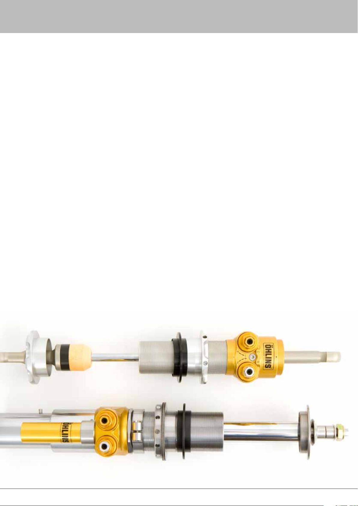
Figure 1.1
Complete TTX40 and TTX46 MT MkII dampers without
springs.
3
Page 5
2 - General Description
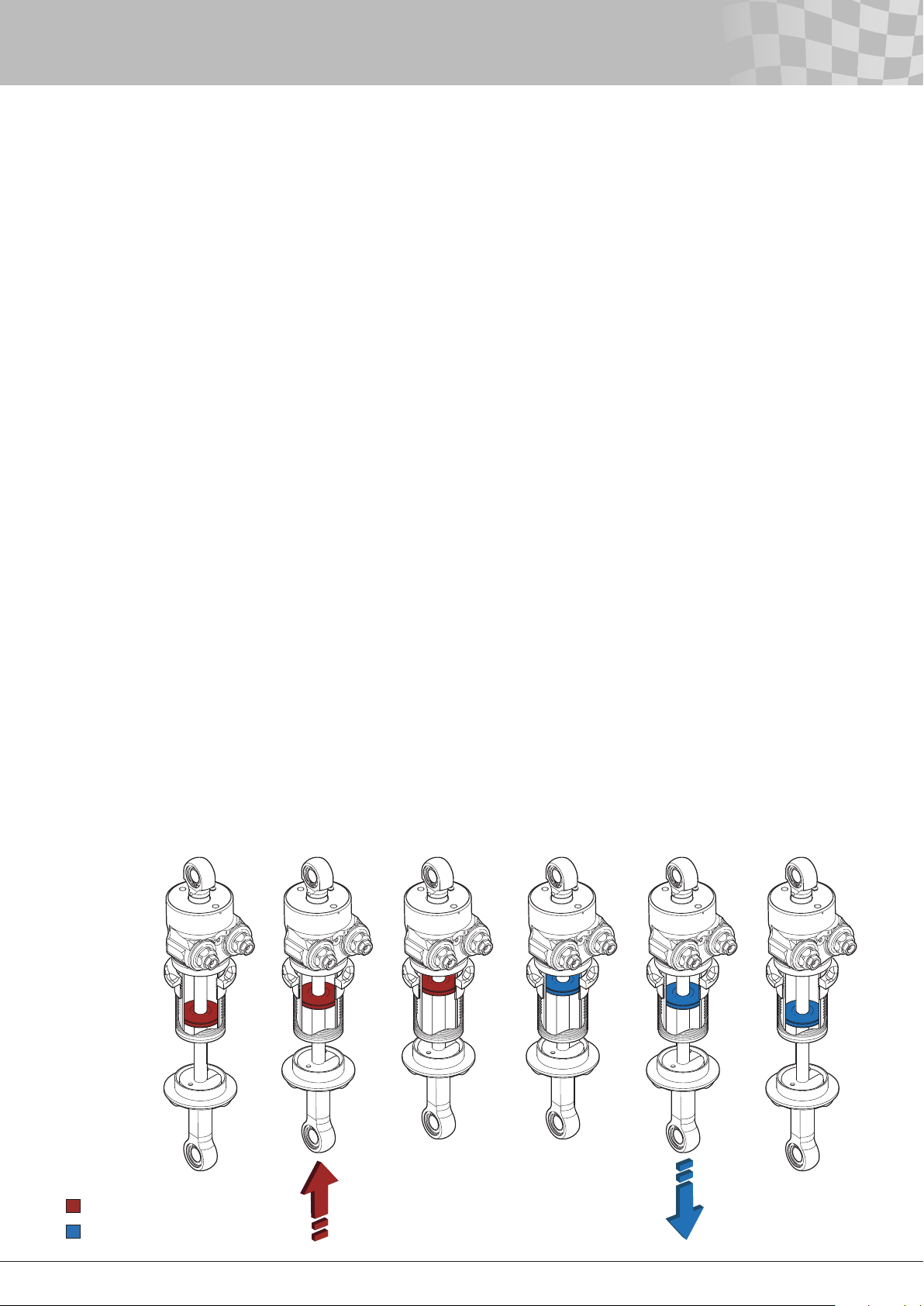
Compression damping cycle Rebound damping cycle
The compression damping cycle describes the situation when the
rod and piston unit moves into the damper body shortening the
length of the damper. While the rebound damping cycle describes
the situation when the rod and piston unit moves out from the
damper body extending the length of the damper.
The terminology ”compression side” of the piston here refers to
the oil volume in front of the piston when the external piston rod is
moving into the damper body (compression cycle). The ”rebound
side ” of the piston refers to the oil volume in front of the piston
when the external piston rod is moving out of the damper body
(rebound cycle).
When the rod and piston unit doesn’t move, the internal
pressure in the whole damper unit is equal with the set gas
pressure. When track conditions cause the vehicle suspension
to move, the damper piston will attempt to move through the
damper oil. In order for the piston to move, oil must ow from
one side of the main piston to the other. The restriction of the
valves causes a pressure difference between the two sides of
the piston, resulting in damping forces. In the TTX40/TTX46MT,
this pressure difference comes from increased pressure on the
forward side of the piston and not reduced pressure on the
backside, as in conventional dampers.
Unless a different valve conguration is used compression
to rebound, the compression and rebound valves are identical
(exceptions are model specic dampers like the BMF and POF
dampers). On both sides in the MkI there are three types and
in the MkII there are two types of valves used for adjusting the
damping characteristics.
• Bleed valve (MkI/MkII)
• Shim valve (MkI/MkII)
• Poppet valve (MkI)
Valve description - TTX40/TTX46MT MkI
The compression bleed valve (low speed) is in parallel with the
compression poppet valve (high speed) and the rebound bleed
valve (low speed) is in parallel with the rebound poppet valve
(high speed). The poppet valves are pushed against their seats by
preloaded coil springs.
The preload is externally adjustable. The amount of preload of
the poppet valves determines the pressure differentials across the
main piston necessary to make the poppet valves open. For more
information about the bleed valves and the poppet valves, see
chapter External adjusters.
The shim valves are placed on the nose of the poppet valves.
These shim stacks affect the opening characteristic of the poppet
valves. The shim conguration can be changed to achieve different
opening characteristics of the poppet valve. Also, there are two
check valves installed in the damper, making the compression and
rebound valves fully independent.
Valve description - TTX40/TTX46MT MkII
The compression bleed valve (low speed) is in parallel with the
compression shim valve (high speed) and the rebound bleed valve
(low speed) is in parallel with the rebound shim valve. The shim
stacks are pushed against their valves by preloaded coil springs.
The preload is externally adjustable. The amount of preload of
the shim stacks determines the pressure differentials across the
main piston necessary to make the shim valves open. For more
information about the bleed valves and the shim valves, see chapter
External adjusters.
The combination of shims on the valve affect the opening
characteristic of the valves. Also, there are two check valves
installed in the damper, making the compression and rebound
valves fully independent.
Figure 2.1
Compression and Rebound damping cycle TTX40
Compression damping cycle
Rebound damping cycle
4
Page 6

6
2 - General Description
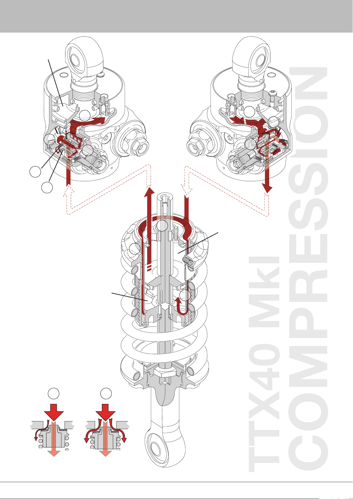
Flow circuit at compression cycle
How the oil flows from the compression side to the rebound side of
the piston will be described here. This is caused by increased pressure
on the compression side of the main piston, while the pressure on the
rebound side is almost constant at the set gas pressure.
1a. TTX40
The oil will reach the compression valves by passing through the
port of the separating plate (fig. 2.3-A and 2.7-A) extending into
the cylinder head and leading the oil into a chamber below the
compression valves (fig. 2.3-B, 2.7-B and 2.8a-B). Because of
the small restriction of this port, the pressure in this camber will
be very much the same as the compression side of the cylinder
tube. The piston velocity and how the valves are set determine
the pressure in the camber. The pressure will help to close the
check valve in this camber.
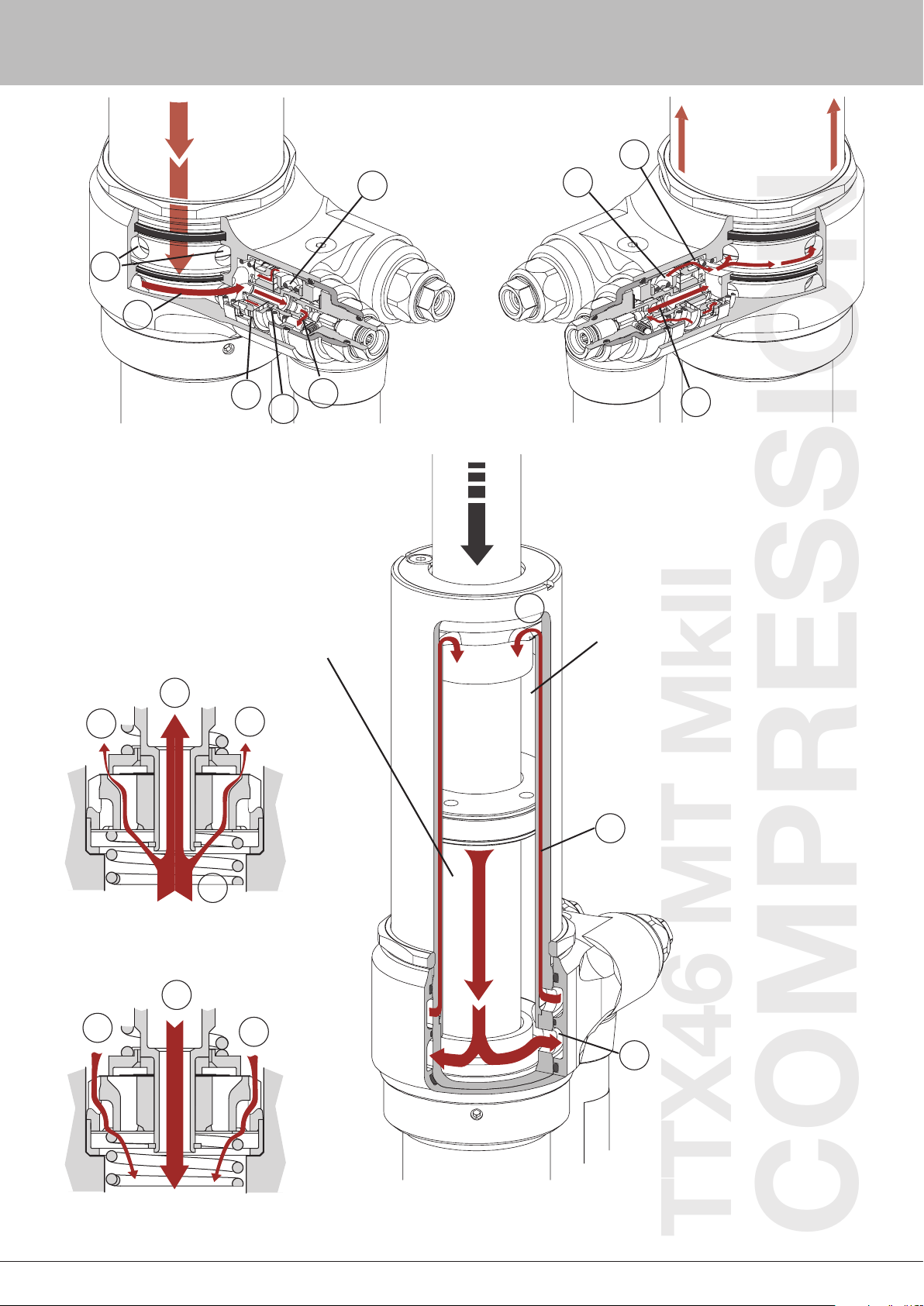
1b. TTX46MT
The oil will reach the compression valves by passing through
the holes in the outer tube (fig. 2.11-A) extending into the
valve housing and leading the oil into a chamber below the
compression valves (fig. 2.11-B). Because of the small restriction
of this port, the pressure in this camber will be very much the
same as the compression side of the cylinder tube. The piston
velocity and how the valves are set determine the pressure in
the camber. The pressure will help close the check valve in this
camber.
2. TTX40/ TTX46 MT
Depending on the pressure, different things will occur. As the
velocity increases, the pressure will rise.
2a. TTX40/ TTX46 MT
In the initial part of a compression stroke, when the velocity
of the piston is low, the oil will pass through the adjustable
low speed compression bleed valve. In this bleed valve, the
restriction takes place in the passage (fig. 2.3-C, 2.6a-C, 2.7-C,
2.10a-C and 2.11-C) between the needle seat (integrated to the
needle housing) and the needle. As long as the piston is moving
and the bleed valve is not fully closed, some oil will always ow
through the bleed valve. If the bleed valve is fully closed, this
passage will be blocked.
2b.1 TTX40/ TTX46 MT MkI
As the velocity increases, the shim stack on the nose of the
poppet valve will start to open and oil can pass between the shim
stack and the poppet valve seat (fig. 2.2-D and 2.3-D). The stack
conguration will decide the opening pressure. An increased
stiffness of the stack will raise the opening pressure and thus
raise the damping force. The shape of the nose on the poppet
valve gives the shims freedom to bend and lift from the seat,
no matter how much preload from spring there is on the poppet
valve. This will allow the shim stack to always open gradually and
therefore a small amount of oil will pass through the shim stack
even with a very low pressure drop over the piston.
2b.2 TTX40/ TTX46 MT MkII
As the velocity increases, the shim on the valve will start to bend
and the valve will start to open and oil can pass between the
shim stack and the valve (fig. 2.6a-D, 2.7-D, 2.10a-D and 2.11-
D). The stack conguration will decide the opening pressure.
All shims with a lager diameter then 20 mm will affect the initial
opening of the stack. An increased stiffness of the stack will raise
the opening pressure and thus raise the damping force. This will
allow the shim stack to always open gradually and therefore a
small amount of oil will pass through the shim stack even with a
very low pressure drop over the piston.
2c.1 TTX40/ TTX46 MT MkI
As the piston velocity increases further, the internal pressure
rises. At a certain velocity the movement of the piston creates
a pressure difference across the main piston that is equal to the
predetermined pressure required to open the poppet valve. The
oil is now free to ow between the poppet valve and the seat (fig.
2.2-E and 2.3-E). Due to the oil ow, the nose shims will follow
the poppet valve up from the seat.
Note!
In practice, the piston often does not reach a velocity high enough to
cause a sufficient pressure drop and open the poppet valve.
By using a very stiff shim stack in combination with little preload on
the poppet valve, the oil ow through the shim stack will be very
limited before the poppet valve opens. This will make the opening
of the poppet valve more abrupt and the shim stack will open at a
higher velocity. This will change the characteristics of the damping
curve.
Note!
The opening characteristic of the poppet valve is always abrupt, unlike
the gradual opening characteristic of the shim stack.
2c.2 TTX40/ TTX46 MT MkII
As the piston velocity increases further, the internal pressure
rises. At a certain velocity the movement of the piston creates
a pressure difference across the main piston that is equal to
the predetermined pressure required to compress the spring
(fig. 2.7-E and 2.11-E) and allow the shims to bend more. The
preload of the spring and the shim stack will determine how
much the shims will bend. The more the shims bend the greater
are the cavities that allows the oil to ow through the valve.
Note!
Usually, the piston does not reach a velocity high enough to cause a
sufficient pressure drop and open the shim valve totally.
5
Page 7

2 - General Description
3. TTX40/ TTX46 MT
The oil has now reached the low-pressure zone at the gas
reservoir (g. 2.3-F, 2.7-F and 2.11-F). This volume is in direct
contact with the separating piston on the TTX40 and connected
to the separating piston by a small hole on the TTX46MT. The
separating piston separates the oil from the nitrogen gas. Here
the pressure is always equal to the set gas pressure. As the
TTX40/TTX46MT is a through rod damper, there will be no uid
displacement by the piston rod. However, a gas volume is still
needed to reduce changes of the static internal pressure due to
volume changes caused by temperature variations. The rising
temperature of the damper will increase the volume of the oil.
Also the damper body will expand as the temperature increases,
but not to the same extent.
4. TTX40/ TTX46 MT
Now the oil will ow through the compression check valve (g.
2.3-G, 2.6b-G, 2.7-G, 2.10b-G and 2.11-G) positioned at the
rebound valves. However, as long as the low speed rebound
bleed valve isn’t fully closed, some oil will ow the through this
valve backwards (g. 2.3-H, 2.6b-H, 2.7-H, 2.10b-H and 2.11-H).
Note!
The compression check valve is placed together with the rebound
valves.
5. TTX40/ TTX46 MT
From here the oil ows between the two tubes (fig. 2.3-I, 2.7-I
and 2.11-I). The oil re-enters the main tube on the rebound side
through ports placed between the end cap and the inner tube
(fig. 2.3-J, 2.7-J and 2.11-J).
The compression ow circuit is completed.
Flow circuit at rebound cycle
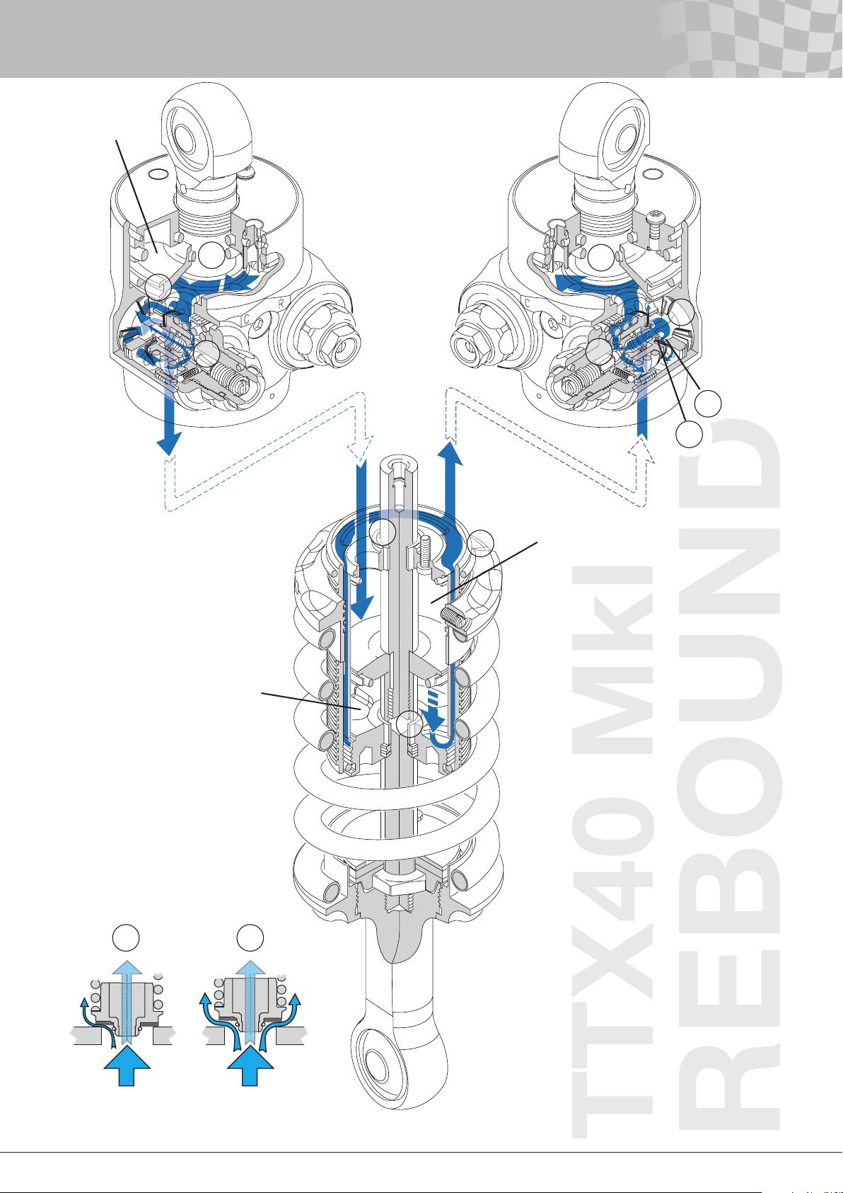
Below is a description of how the oil flows from the rebound side to the
compression side of the piston. The rebound cycle is very similar to the
compression cycle, but the flow will be in the opposite direction and
the oil will move through different valves. During the rebound stroke, the
pressure of the rebound side of the main piston is increased, while the
pressure of the compression side is kept almost constant.
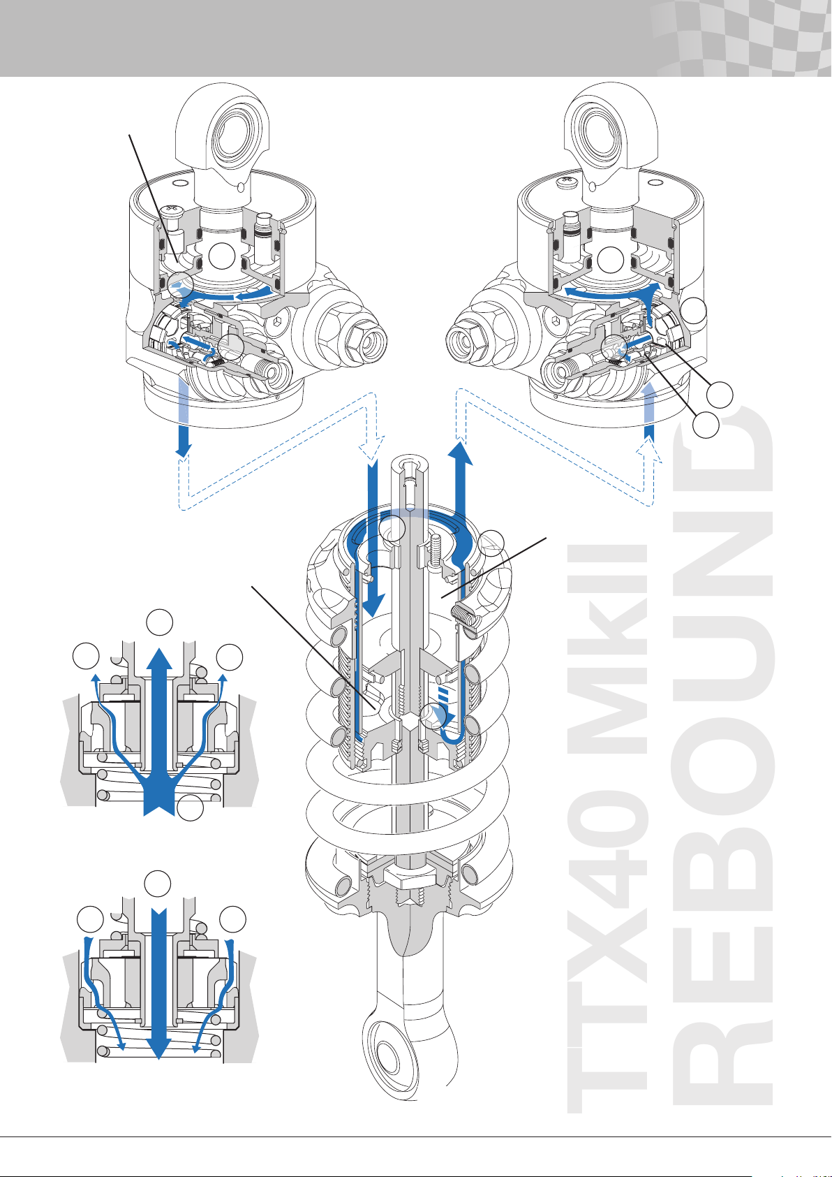
1a. TTX40
First of all, the oil has to get to the rebound valves. The ports
between the end cap and the inner tube (fig. 2.5-A and 2.9-A) will
lead the oil to the volume between the tubes (fig. 2.5-B and 2.9-
B) from where the oil will reach the chamber below the rebound
valves (fig. 2.5-C and 2.9-C). The pressure here will be roughly
the same as in the rebound side of the cylinder tube due to small
restrictions of the oil ow. The pressure will help to close the
check valve in this camber.
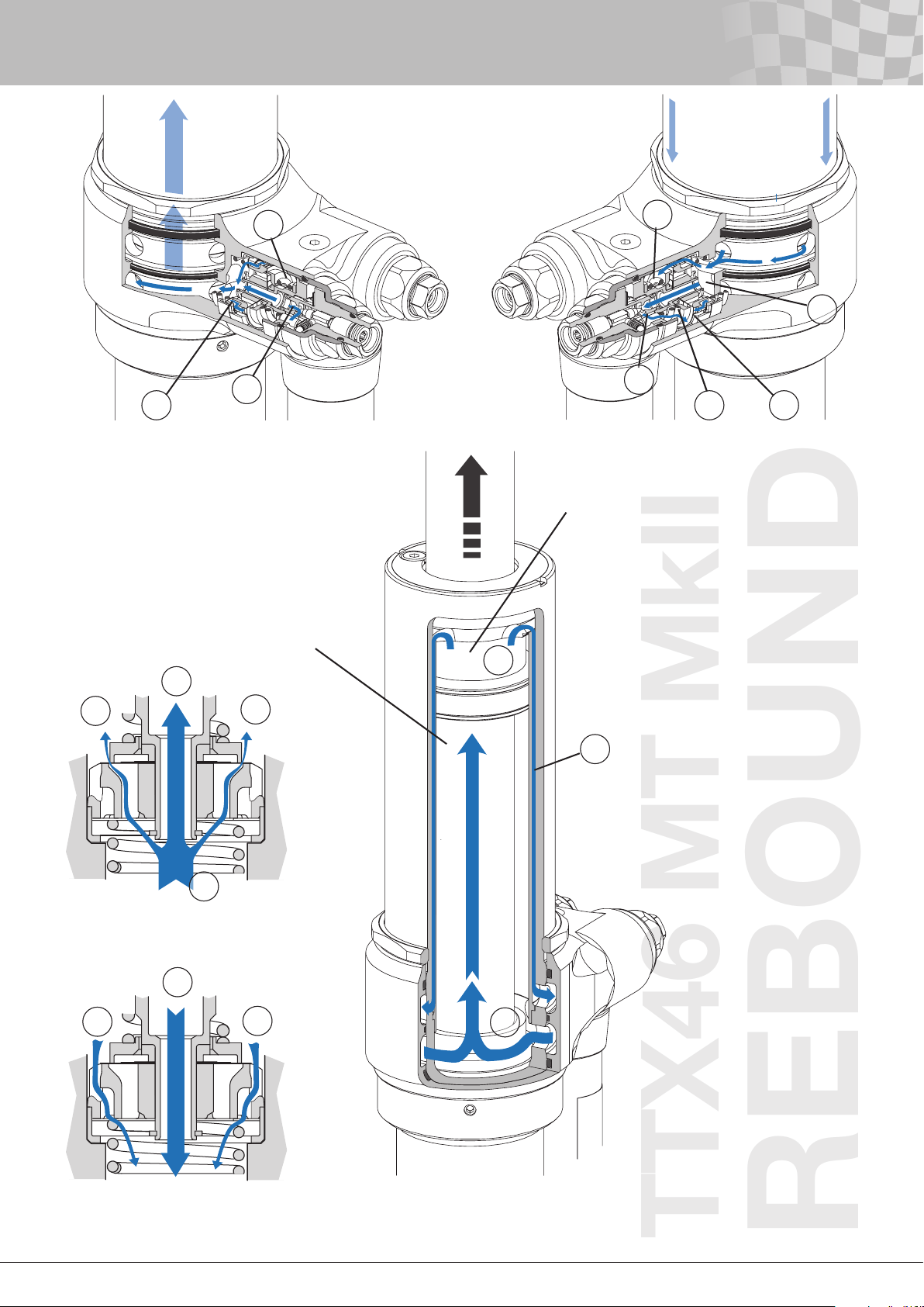
1b. TTX46MT
First the oil has to get to the rebound valves. The ports between
the upper seal head and the inner tube (fig. 2.13-A) will lead the
oil to the volume between the tubes (fig. 2.13-B) from where the
oil will reach the chamber below the rebound valves (fig. 2.13-C).
The pressure here will be roughly the same as in the rebound side
of the cylinder tube due to small restrictions of the oil ow. This
pressure will help to close the check valve in this camber.
2. TTX40/ TTX46 MT
See section 2. TTX40/ TTX46 MT under Flow circuit at
compression cycle in this chapter for more detailed information
as the rebound valves are identical to the compression valves.
2a. TTX40/ TTX46 MT
Unless the low speed rebound valve is fully closed, the oil will
rst pass through this valve
(fig.2.5-D, 2.8a-D, 2.9-D, 2.12a-D and 2.13-D).
2b.1 TTX40/ TTX46 MT MkI
The second valve to open is normally the nose shim stack (fig.
2.4-E and 2.5-E).
2b.2 MkII
The second valve to open is the shim stack on the valve (fig.
2.8a-E, 2.9-E, 2.12a-E and 2.13-E). It starts with the largest
shims, diameter more than 20 mm, starts to bend and in this way
lets the oil ow through the vavle.
2c.1 MkI
If the pressure level reaches the opening pressure of the poppet
valve, the poppet valve will open (fig. 2.4-F and 2.5-F).
2c.2 MkII
If the pressure level reaches the opening pressure of the spring
valve, the spring will let the preload ring to lift and the shim stack
will let more oil through the valve (g. 2.9-F and 2.13-F).
3. Now the oil has reached the low-pressure zone at the gas
reservoir (fig. 2.5-G, 2.9-G and 2.13-G), where the pressure is
equal to the gas pressure.
4. The oil will now ow through the rebound check valve (fig.
2.5-H, 2.8b-H, 2.9-H, 2.12b-H and 2.13-H) positioned at the
compression valves. Some oil can, in the same way as described
above in Flow circuit at compression cycle, ow backwards
through the low speed compression valve (fig. 2.5-I, 2.8b-I, 2.9-I,
2.12b-I and 2.13-I) unless it is set to the fully closed position.
Note!
The compression check valve is located together with the rebound
valves.
5. Finally the oil re-enters the main tube on the compression
side through a port in the separating plate (fig. 2.5-J, 2.9-J and
2.13-J).
The rebound circuit is completed.
6
Page 8
8
2 - General Description
TTX40 MkI
COMPRESSION
Gas volume
F
B
C
D
E
A
I
Compression side
F
G
H
Rebound side
D E
Figure 2.2
Poppet valve for compression TTX40 MkI.
J
Figure 2.3
Flow circuit during compression cycle for TTX40 MkI.
7
Page 9
TTX40 MkI
REBOUND
Gas volume
2 - General Description
G
H
I
J
B
Compression side
G
C
D
E
F
Rebound Side
E F
A
Figure 2.4
Poppet valve for rebound TTX40 MkI.
Figure 2.5
Flow circuit during rebound cycle for TTX40 MkI.
8
Page 10
10
2 - General Description
TTX40 MkII
COMPRESSION
Gas volume
F
B
C
D
E
A
Rebound Side
C
D
D
I
Compression side
F
G
H
B
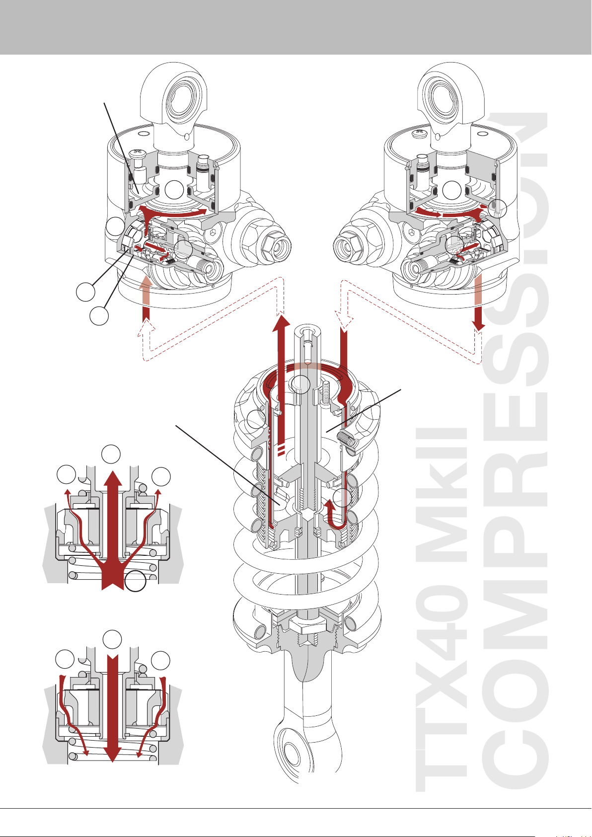
Figure 2.6a
Flow through the main valve TTX40 MkII.
H
G
Figure 2.6b
Flow through the check valve TTX40 MkII.
G
J
Figure 2.7
Flow circuit during compression cycle for TTX40 MkII.
9
Page 11
TTX40 MkII
REBOUND
Gas volume
2 - General Description
G
H
I
J
Rebound Side
D
E
E
Compression side
B
G
C
D
E
F
Figure 2.8a
C
Flow through the main valve TTX40 MkII.
I
HH
Figure 2.8b
Flow through the check valve TTX40 MkII.
A
Figure 2.9
Flow circuit during rebound cycle for TTX40 MkII.
10
Page 12
12
2 - General Description
TTX46 MT MkII
COMPRESSION
G
F
A
B
D
Compression side
C
E
J
F
H
Rebound side
C
D
Figure 2.10a
Flow through the main valve TTX46 MT MkII.
H
G
D
B
G
I
A
Figure 2.10b
Flow through the check valve TTX46 MT MkII.
Figure 2.11
Flow circuit during compression cycle for TTX46 MT MkII.
11
Page 13
2 - General Description
TTX46 MT MkII
REBOUND
G
I
H
Rebound Side
Compression side
A
D
G
C
D
EF
E
Figure 2.12a
Flow through the main valve TTX46 MT MkII.
H
C
I
E
H
B
J
Figure 2.12b
Flow through the check valve TTX46 MT MkII.
Figure 2.13
Flow circuit during rebound cycle for TTX46 MT MkII.
12
Page 14

14
3 - Damping Force Measurement
Damping forces is a frequent subject of discussions at race
weekends. It is important to understand that depending on how the
damping forces are measured, the force values can turn out very
differently.
Within a race team, where the values normally always come from
the same source this is normally not a problem. A team mainly
needs a damper dynamometer to ensure their dampers produce the
damping forces that are expected. This means that no “heavy duty”
dynamometer is needed. For formula racing applications and many
other types of asphalt racing a dynamometer that can reach 5 inch/
second (0.127 m/s) is enough. The type of dynamometers mainly
used are of the “crank type”. The price tag, size and simplicity are
the main advantages of these machines. A crank dynamometer
can be used for “continuous measurement” or “peak velocity
measurement”. A hydraulic dynamometer can be used for any type
of measurement.
The requirements for a damper manufacturer, doing research and
development, are very different and other types of machines are
needed.
There is not one perfect way of measuring damping forces, as
different situations ask for different needs.
See chapter Damping curve terminology for information about
how to read damping graphs.
For a race team a continuous measurement of the damping force
is very good: the measurement is quick, makes it very easy to tune
the damping curve to a desired shape, hysteresis and cavitation is
easy to detect and “dynamic problems” can be found. An example
of a dynamic problem that can be detected this way is sticking
check valves.
With continuous measurement of the damping force, the damper
movement mimics a “sine wave”, often in the region of 1.6 Hz.
As both the acceleration and the deceleration part can be seen,
there will be two force values for any given velocity except for the
maximum velocity. Sometimes the terminology “dynamic testing”
is used for this type of damper testing, including other types of
movements than just sine wave movements, but with the common
factor that the measurements are done during variations in velocity.
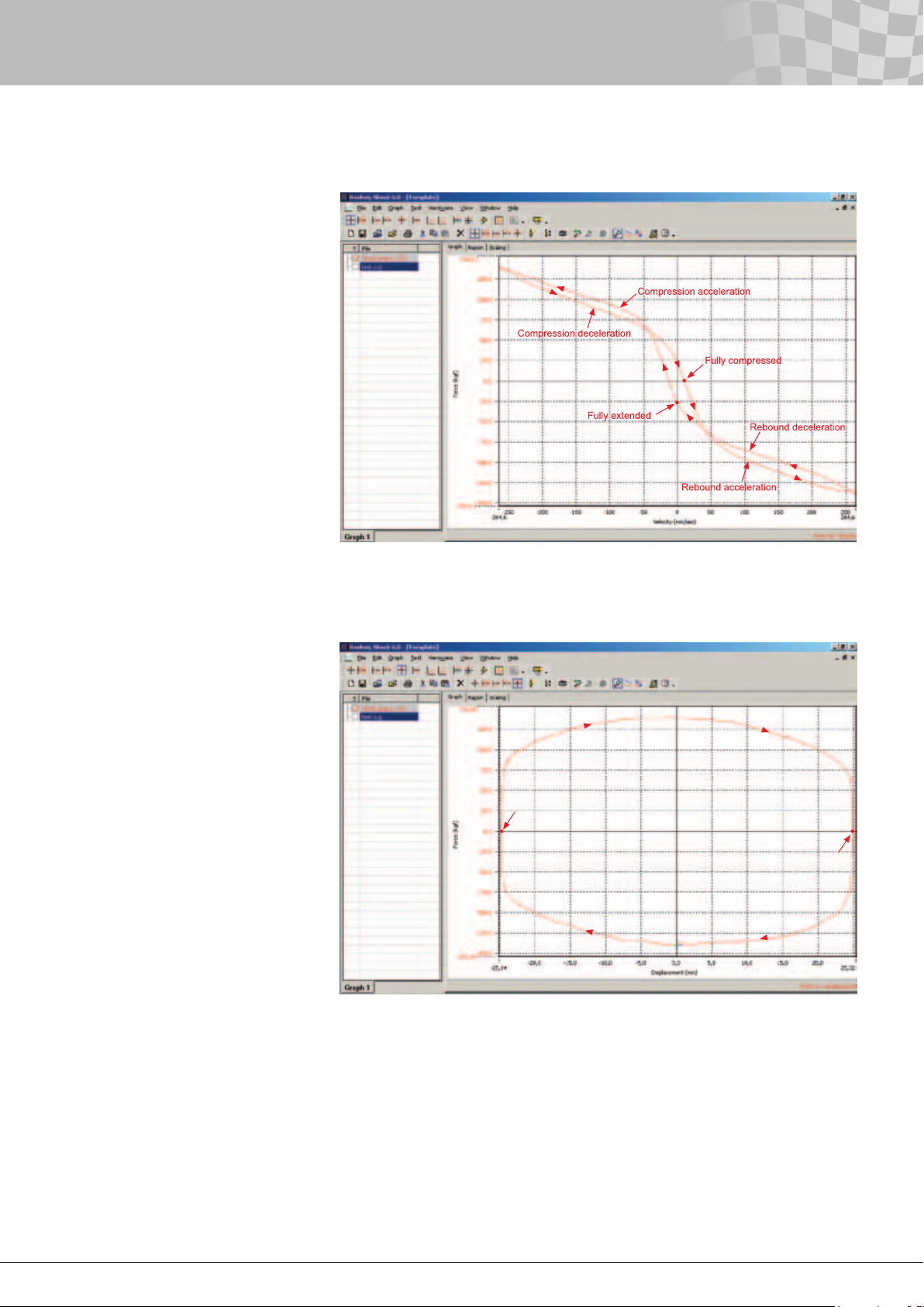
As can be seen in the gure, the acceleration force values are lower
than the deceleration force values when passing zero velocity. This
separation at low velocities is called “hysteresis”. See chapter
Hysteresis for more information. When ”matching” dampers, the
teams often pick half of the cycle to keep the overlay of curves
from different dampers as clean as possible. It is common to use
compression opening (measurement during acceleration) and
rebound closing (measurement during deceleration).
Many times the result of continuous damping force measurement
can be presented in a force-displacement graph. These types of
curves are sometimes named “egg curves”.
If continuous measurement is used, the forces given are
dependent on the stroke and frequency being used. By changing
the crank length and the frequency of the dynamometer machine
so to maintain the same peak velocity, let say 5 inch/second, the
damping force curves will change. From the formula below, you nd
that, for example, a reduction of the amplitude to half will give the
same peak speed if the frequency is doubled.
v
= A • 2π • f [ m/s ]
max
v
= peak velocity [ m/s ]
max
A = amplitude [ m ]
f = frequency [ Hz ]
The less travel required to reach a specic velocity, the more
pronounced the hysteresis will be in the graph. As hysteresis is
found when the movement change direction, in other words at zero
velocity, tests where different strokes have been used to produce
the same peak velocity will differ at low velocities due to hysteresis.
See chapter Hysteresis for more information.
13
Page 15
3 - Damping Force Measurement
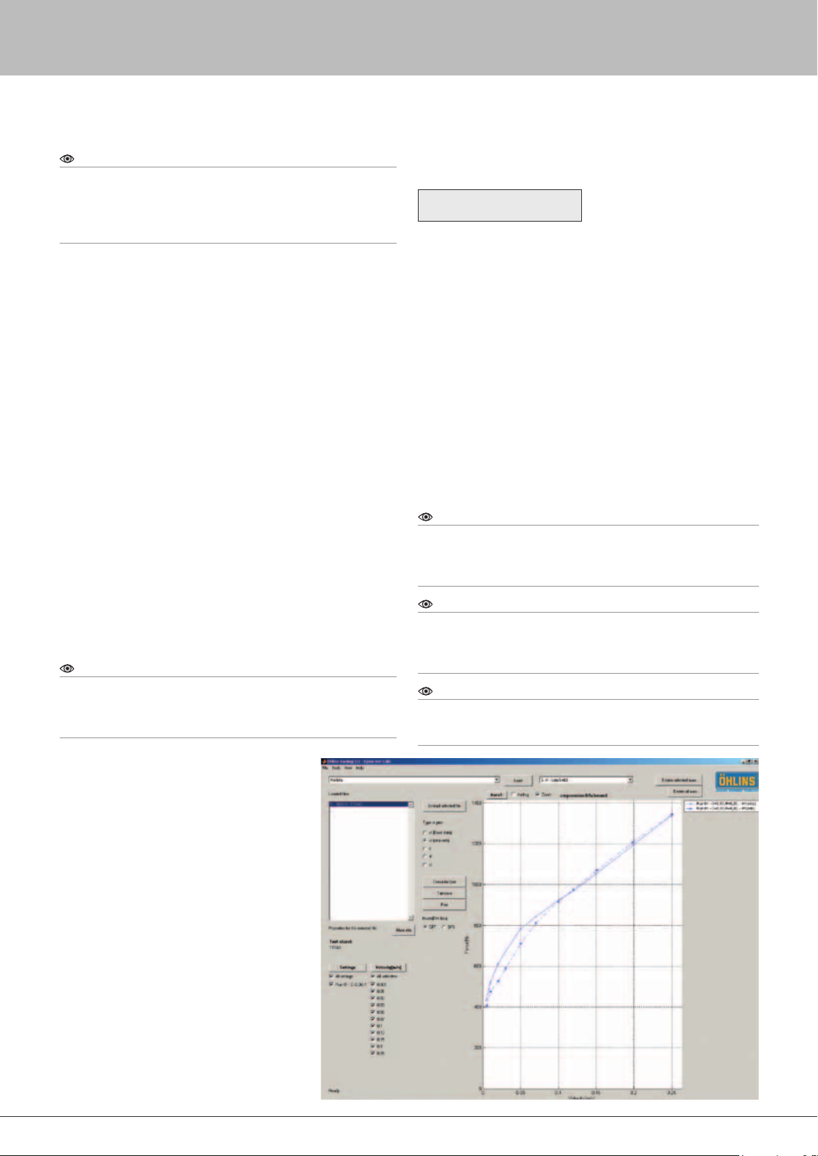
Figure 3.1
Damping force measured continuously in a
Roehrig dynamometer.
The bleeds are fully closed.
Figure 3.2
Damping force measured continuously in
a Roehrig dynamometer.
Here the result is presented in a
force‑displacement graph.
The data comes from the same run as in
the previous figure.
Fully extended
Fully compressed
14
Page 16
16
3 - Damping Force Measurement
Note!
Comparing the forces figures 3.2 with the force of 3.3, there is a huge
difference in force at low speed. When the damping force is measured
continuously the hysteresis give the impression that the bleeds are
quite open and a small bleed change can be hard to notice in the
graph.
Sometimes the software uses a lter to reduce the level of noise in
the graphs. Some race teams do damping force measurement at
constant velocity.
Sometimes the terminology “static testing” is used for this type
of testing. For matching dampers this method is excellent. For
a damper manufacturer, working with different race teams using
different methods of measuring damping forces, measuring at
a constant velocity is preferred. Otherwise as explained above,
when using continuous measurement, there is always a risk that
the values discussed comes from different methods of measuring.
When the damping force is given at a constant velocity, there is
only one value of the damping force at each specic velocity.
A crank dynamometer can’t be used for constant velocity
measurement, but by measuring the damping force at different
peak velocities, the result is normally very close.
When a crank dynamometer is used, the machine always
produces sine wave movement. By changing the frequency of the
dynamometer, different peak velocities are reached.
The number of runs varies depending on the needs. Of course
small steps extend the test time. In a hydraulic dynamometer,
the piston rod is accelerating to the desired velocity in a short
distance, and the ow of oil through the valves in the damper
is kept “static” during a large part of the stroke. This makes
it possible to take hundreds of measurement before the
dynamometer decelerates the piston rod.
Note!
In this manual, if there is no other information, all graphs illustrated
come from Öhlins TTX VRP. The data used in the TTX VRP are
produced by an Instron hydraulic dynamometer at Öhlins Laboratory.
The forces are measured at constant velocity.
It is very important to know when dynamometer
testing dampers if the forces measured are
compensated for gas force or not.
Most racing dampers (pressurised, and not
through rod type) add a gas force to the damping
force. The gas force should be seen as an extra
spring force from a spring with very low rate. This
force is position dependant (close to constant)
and not velocity dependant and should therefore
be removed when damping force is plotted.
An idea of the amount of gas force a damper
produces at a specic piston position (normally
small variations at piston positions) can be found
by compressing the damper by hand and keeping
it at a static position. The gas force will now try to
push the piston rod out of the damper body.
This force is calculated as
F
= p
• A
rod
p
= gas pressure above atmosphere pressure
gas
(the value read on the pressure gauge when
pressurizing the damper) [N/m2, 1 bar=105 N/m2 = 15 psi]
A
= piston rod area
rod
For example, at 10 bar (15 psi) gas pressure in the TT44/40 (∅16
mm piston rod), the gas force is approximately 200 N (45 lbs).
When you look at a dynamometer curve that has been gas force
compensated, you are looking at the actual damping forces
produced by the damper.
For non gas compensated dynamometer curves, the actual
damping forces are calculated from the formulas below.
Compression damping = measured compression force – Frod
Rebound damping = measured rebound force + Frod
The TTX damper has no resulting force from the gas pressure (Frod
= 0), so it always gives the same forces no matter if the testing is
gas compensated or not.
[ N ]
gas
rod
Note!
If matching the forces from a TTX damper with the forces from a
conventional damper tested without gas compensation, the forces of
the conventional damper has to be gas force compensated with the
formulas above to get the same amount of damping.
Note!
Keep in mind that even if the method for measuring the damping
forces is identical there can be some small variations in the result from
different damper dynamometers, due to individual variations between
the machines.
Note!
All damping curves will change with temperature, so always keep
track of the temperature. See chapter Temperature stability for more
information.
Figure 5.3
Damping force measured at constant velocity.
The lined curve is compression, the dotted
curve is rebound. The setting is the same as in
the two previous figures.
15
Page 17
4 - Damping Curve Terminology
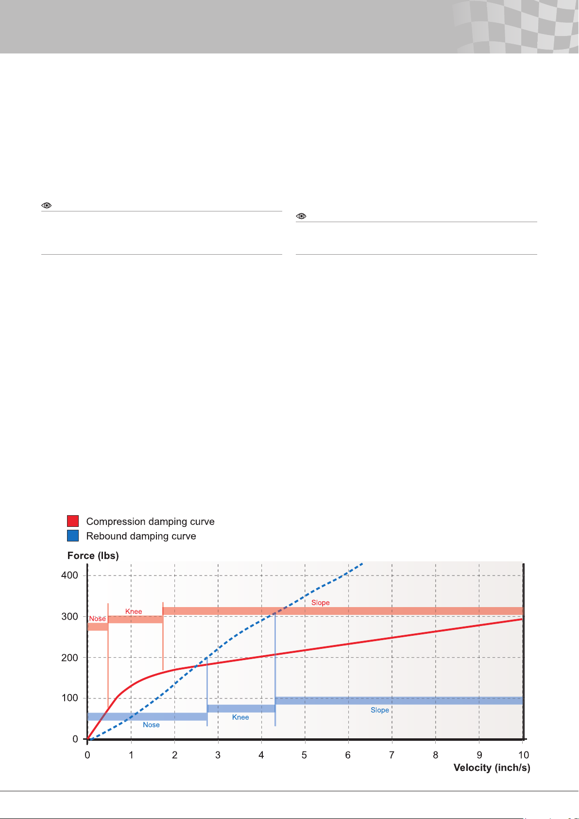
In order to understand the next part of this manual we must all
speak the same language. In the damper industry there are terms
used to help describe different parts of a dynamometer graph.
The three key words are nose (low speed), knee and slope
(high speed). Careful study of this section will yield a complete
understanding of these terms and allow you to read damper curves.
The horizontal axis in the gure gives damper velocity and the
vertical axis shows damping force.
Note!
The velocity of the damper refers to the velocity of the piston rod
movements, not to the speed of the car. Most of the piston rod
movements on a race car reach only low velocities and the percentage
number of strokes going though all zones described below is low.
Take a look at the gure above and notice the rst portion of the
damping curves – starting at 0 inch/second and ending at about 0.4
inch/second on the compression curve and about 2.7 inch/second
on the rebound curve. This part of the curve is called the nose and
is also referred to as low speed. The valve affecting this part of the
curve is the low speed adjuster. It is always of a xed orice type
(the size of the orice is not variable by pressure, but by clicker
adjustments) and is often called bleed. The design and size of the
bleed determines the characteristics and shape of the nose.
The nish of the nose zone coincides with the beginning of the knee
zone. Its location in the curve can be found by identifying where the
upwards curve rst begins to level off into a radius. Locating where
the knee radius stops and blends into the straight line identies the
end of the knee zone and the beginning of the slope zone.
The shape of the knee is determined by the opening characteristic,
gradual or abrupt. The more abrupt the opening phase is, the
sharper the knee will be. The converse is also true. Normally the
shape of the curve in the knee zone comes from the transition
of the shims bending and when the force is big enough to start
compress the high speed spring. At 1.2 inch/second the valve
has totally gone from the shims bending to the spring opening.
Due to the more open bleed on the rebound. The knees are not so
pronounced.
Note!
Wide open bleeds in combination with a stiff shim stack and a lot of
preload can allow the low speed zone to extend into relatively high
velocities.
The shim stack and the preload of the coil spring normally
determine the slope, also referred to as high speed. In most cases
the slope will continue to rise in a straight line to damper speeds
well beyond those found in most racing dynamometer charts.
Eventually the slope will increase at an exponential rate. This
happens when the size of the channels transporting the oil begin to
restrict the oil ow (channels are also xed orices).
The slope angle relative to the horizontal plane denes the
magnitude of the slope and can be quantied as Pound/(Inch/
Sec.) or N/(m/s). The nose, knee and slope are key words to
understanding the following concepts.
Figure 4.1
Terminology
16
Page 18
18
5 - External Adjusters
General description
Most dampers that are external adjustable have some type of low
speed adjuster. Low speed adjusters are almost always externally
adjustable orices that become xed after adjustment. Fixed in the
sense that the orice area is not dependent on the pressure drop
over the orice.
In the damper industry, these adjustable orices are often
referred to as bleeds or low speed adjusters. Unlike shim stacks,
bleed orices do not change size in response to changes in
pressure. Because oil will always travel the path of least resistance,
it will rst ow through the open bleeds until there is enough
pressure to open any other valves. Oil ows through the bleeds any
time the piston rod is moving, and continues to ow in parallel with
the ow through the piston shim stack after the stack has opened.
The most common type of external high speed adjuster is an
adjuster that moves the knee up or down without changing the
slope, or just marginally changing it. To achieve this, the amount
of force pushing the valve, shim or poppet valve, against its seat is
varied. That is done by changing the preload of the spring element,
shim stack, coil spring, cup spring etc.
The oil ow that is controlled by the external adjusters varies
between different type of dampers. The larger the ow is, the better
the conditions will be for a powerful adjuster. There are two reasons
for that.
• A larger ow is easier to control. The tolerances for the
dimensions on the valve parts have to be tightened if the ow is
reduced.
External adjusters summarised
The TTX40/TTX46MT damper from Öhlins comes as a 4-way
externally adjustable damper. As some racing classes have
rules about the maximum number of external adjusters there is
a possibility to change the vales to a valve that is only one way
adjustable.
By changing just one valve you can make the damper 3-way
adjustable and by changing both valves you can make it 2-way
adjustable. This valve has the high speed adjuster lock or only a low
speed (bleed) adjuster. To adjust the high speed in this valve you
need to take the valve out of the damper and re-shim it. The text
below describes the valves that the dampers are delivered with.
• A larger pressure area, the pressure area is proportional to the oil
ow, will keep the internal pressure of the damper at a lower level.
This increases the damper response and the damper will build up
damping force quicker.
Figure 5.1
External adjusters
17
Page 19
5 - External Adjusters
Low Speed Compression Damping Adjuster (LSC)
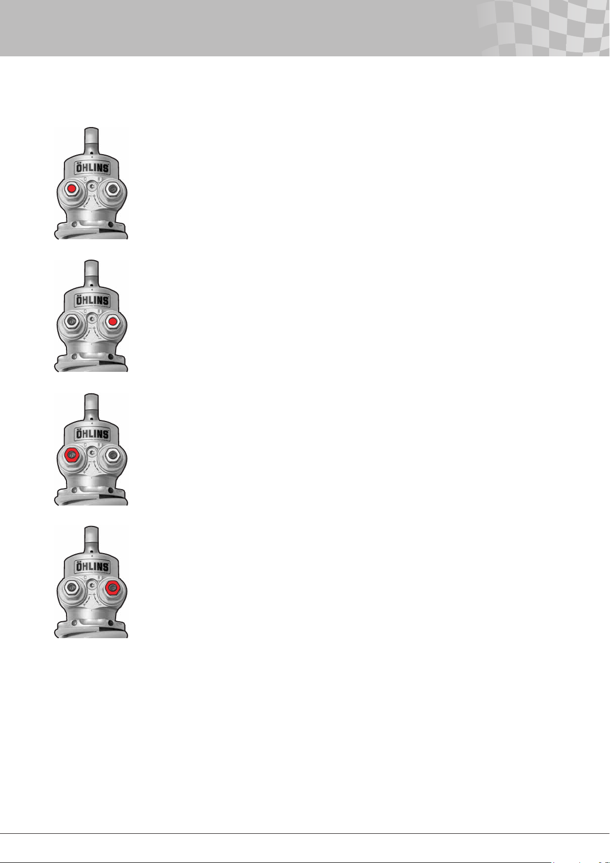
Type of adjuster: Bleed adjuster
Effects: The ow from the main piston during a compression stroke only.
Pressure area*: TTX40: 1143 mm2 (Ø40-Ø12) (12 mm shaft)
TTX40: 1103 mm2 (Ø40-Ø14) (14 mm shaft)
TTX46MT: 955 mm2 (Ø46-Ø30)
Identication: The black screw with an internal 3 mm hex inside the gold
12 mm hex at the cylinder head.
Number of positions: 40
Click position 0: Fully clockwise at maximum force (orice closed).
Low Speed Rebound Damping Adjuster (LSR)
Type of adjuster: Bleed adjuster
Effects: The ow from the main piston during a rebound stroke only.
Pressure area*: TTX40: 1143 mm
TTX40: 1103 mm2 (Ø40-Ø14) (14 mm shaft)
TTX46MT: 955 mm2 (Ø46 - Ø30)
Identication: The black screw with an internal 3 mm hex inside the silver
12 mm hex at the cylinder head.
Number of positions: 40
Click position 0: Fully clockwise at maximum force (orice closed).
2
(Ø40-Ø12) (12 mm shaft)
High Speed Compression Adjuster (HSC)
Type of adjuster: Spring preloaded shim stack or spring pre-loaded shimed poppet valve.
Effects: The ow from the main piston during a compression stroke only.
Pressure area*: TTX40: 1143 mm
TTX40: 1103 mm2 (Ø40-Ø14) (14 mm shaft)
TTX46MT: 955 mm2 (Ø46 - Ø30)
Identication: The golden 12 mm hex at the cylinder head/valve housing.
Number of positions: Approx 50
Click position 0: Fully clockwise at maximum force (spring max preloaded).
High Speed Rebound Adjuster (HSR)
Type of adjuster: Spring preloaded shim stack or spring pre-loaded shimed poppet valve.
Effects: The ow from the main piston during a rebound stroke only.
Pressure area*: TTX40: 1143 mm
TTX40: 1103 mm2 (Ø40-Ø14) (14 mm shaft)
TTX46MT: 955 mm2 (Ø46 - Ø30)
Identication: The silver 12 mm hex at the cylinder head.
Number of positions: Approx 50
Click position 0: Fully clockwise at maximum force (spring max preloaded).
* As it is a through rod damper, the compression and rebound pressure areas are the same. The pressure area
multiplied with the piston velocity give you the flow (volume per time unit) of oil that passes through the valves.
2
(Ø40-Ø12) (12 mm shaft)
2
(Ø40-Ø12) (12 mm shaft)
18
Page 20
20
5 - External Adjusters205 - External Adjusters
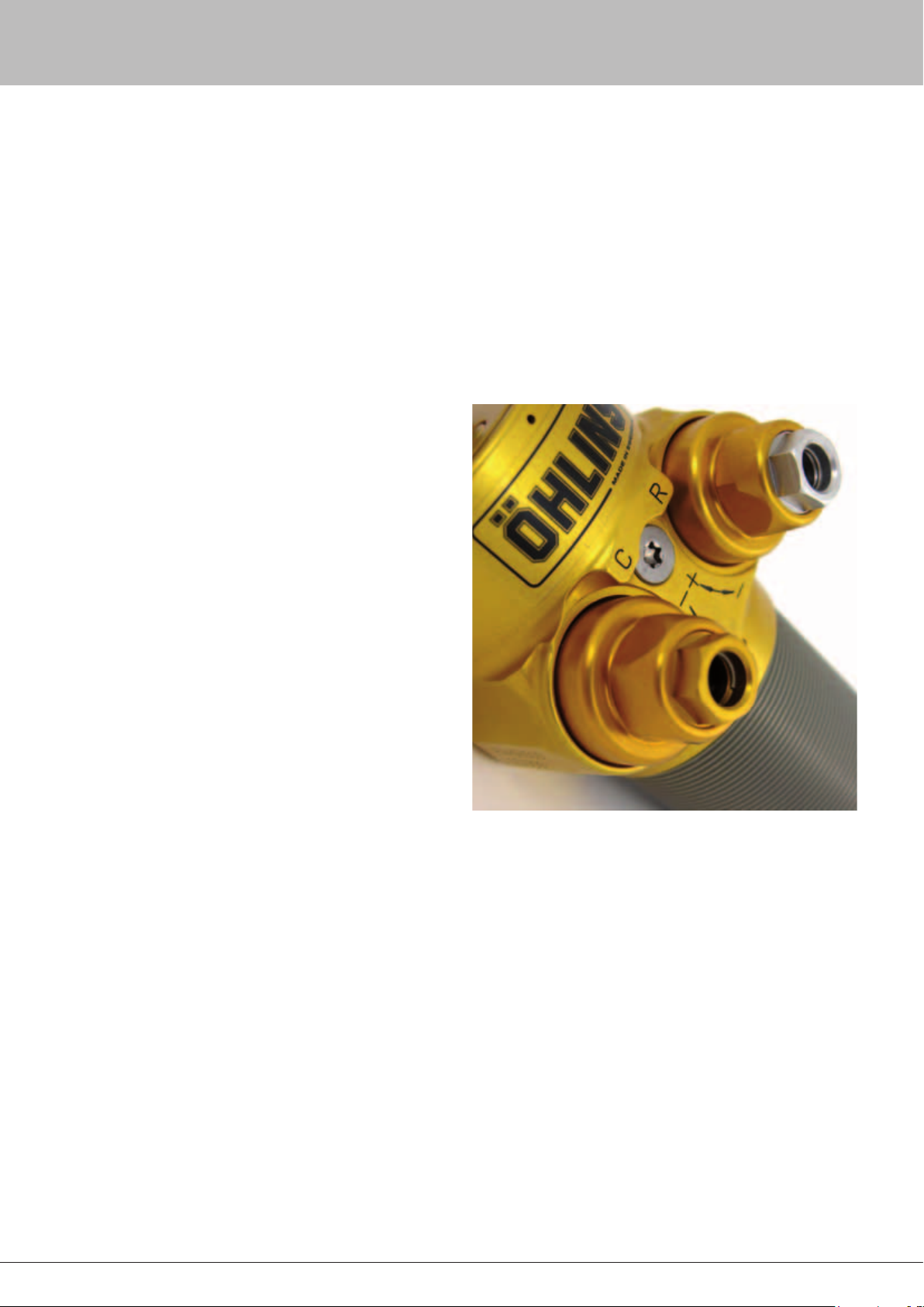
As can be seen in the gure, the cylinder head on the TTX40 is
market “C” and “R” together with “+” and “-”. This will help the rst
time users to separate Compression from Rebound and tells what
direction the adjusters should be turned to increase (+) or reduce (-)
damping. On the TTX46MT there is no “C” and “R” or “+” and “-“.
This is due to that the valve housing is a symmetrical part and we
would like to keep the possibility to turn the valve housing around
which gives the possibility to have the reservoir pointing upward.
Note!
All external adjusters are ”fully hard” when turned clockwise until they
stop. The clicker positions, including the high speed adjusters, is always
counted from ”fully hard”. Never over tighten the adjuster since this can
damage the valve.
The reason that ”full hard” is used, is that it always is an absolute
position. ”Fully soft” will vary more depending on the tolerances,
so the matching wouldn’t be as good if the clicker positions were
counted from full soft. The rst click and/or detent is counted as
”zero” position.
To match damping curves of a pair of dampers in the
dynamometer, sometimes the clicker numbers will end up a couple
of clicks from each other. Often they match within ± 1-2 clicks,
but sometimes you can see ± 3 clicks. Just remember maximum
clockwise is “full hard” for all adjusters and the adjusters are
counted from full hard.
Low speed adjusters
The TTX40/TTX46MT features two
fully independent low speed adjusters
adjusting the main piston oil ow. For
a specic damping force, the internal
pressures can be kept low, giving a
minimum of delay in the damping force
build up. The two low speed adjusters
(bleeds) LSC and LSR are identical
and are designed so that in the normal
operating range each click of the
adjusters will change the damping in
close to equal steps. They are tapered
needles working in xed orices, but due
to a double coned nose of the needle,
the damping force doesn’t increase
progressively per click as the needle is
closed. The adjusters are powerful over
the whole range making it easier to nd
the optimum settings.
Both adjusters have a range of
approximately 40 clicks. Normally they
match within ± 2 clicks. The bleeds are
adjusted with a 3 mm Allen key. Do not
use too much torque when closing the
bleeds completely. Generally it is better
to start with the adjusters a little more
open and gradually close them off. See
chapter Damping guidelines for more
information.
Low speed adjusters effect on damping curve
Assuming the LSC and the LSR have the same clicker setting, the
piston velocity is the same and that there is no oil owing through
the high speed, exactly the same amount of oil will ow through
both valves. The LSR has exactly the same affect on the nose of the
rebound damping curve (see chapter Damping Curve Terminology
for more info) as the LSC has on the nose of the compression
damping curve.
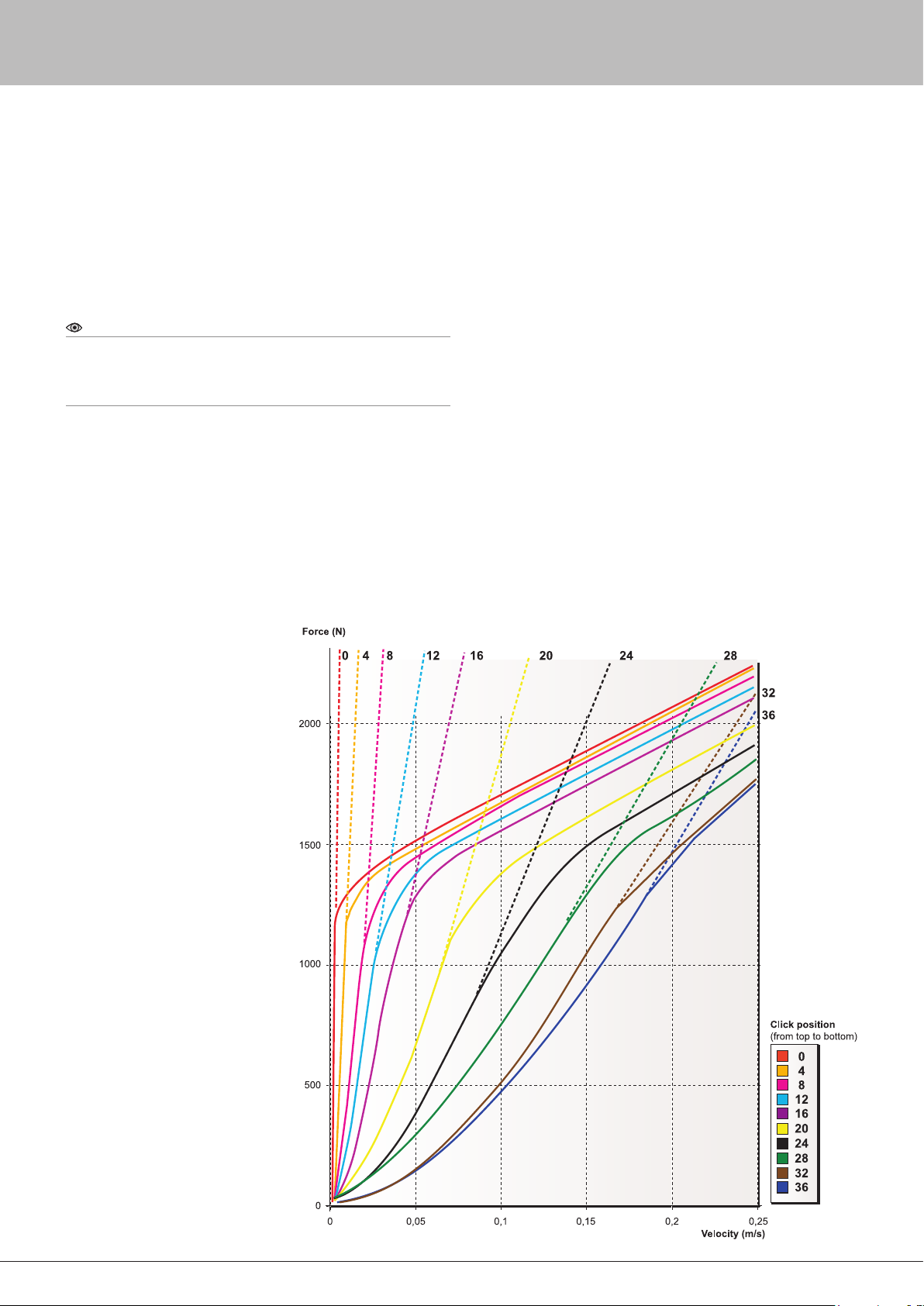
The different curves in gure 5.2 are achieved by adjusting only
the LSC/LSR. The numbers above the curves represent low speed
adjuster clicker settings. The dotted curves pointing upwards
indicate the theoretical shape of the curves if there was only a low
speed valve and no high speed valve to open. The valve used here
is for information use only.
For real values for the VRP (Valving Reference Program) - see
www.ohlins.com. If the adjuster is turned counter clockwise the
clicker numbers get higher. As the bleed is opened more and more,
the damping is reduced and the speed at which the knee starts
increases and the nose is stretched longer and longer. Also, the
force of the knee and the slope angle will remain the same. This is
because only the high speed valve determines the knee height and
the slope.
This means that even the high speed damping will drop as the
low speed adjuster is opened. The more slope there is, the more
the high speed will drop.
Figure 5.2
Influence of the low speed
adjusters. The graph represents
both the LSC and the LSR.
19
Page 21

Conversely, if you wish to keep the knee force constant, the spring
(high speed) preload has to be increased every time the low speed
adjuster is opened. If the low speed adjuster instead is turned
clockwise, the opposite from above will be true.
High speed adjusters
The TTX40/46MT has two high speed adjusters; one for
compression and one for rebound. A damper like the TTX 40/46MT
is often called fully adjustable. This provides race engineers and
technicians with more external control over the damping. Anything
that can make an adjustment quicker and thereby gain time during
practice and qualifying is important.
Just as the low speed adjusters, the high speed adjusters HSC
and HSR are identical (only the colour of the needle housing is
different, gold for compression and silver (clear) for rebound, fully
independent and adjust the main piston ow. They are delivered
with the same valving, except the model specic dampers like the
BMF or POF kits.
Both high speed adjusters on the MkI consist of a poppet valve
preloaded by a coil spring. The coil spring pushes the poppet
against its seat. On the MkII the both high speed adjusters
consist of spring preloaded shim stacks. The preload of the spring
determines the pressure differential needed to make the valve open.
The adjusters change the amount of preload. A preload change will
change the height of the knee. Each click of the adjusters changes
the damping in almost equal steps.
Both valve types work the same way. Both are pressure
regulators that control the oil ow by opening at a pre-determined
pressure and thereby providing a path for the oil to ow. In the nose
of the poppet valves, on the MkI dampers, shims make it possible
to adjust the sharpness of the knee. There are alternative poppet
valves with corresponding valve seats. There are also other springs
available. See the MkI VRP and the Spare Parts List for more
information about the parts.
Alternative parts for the MkII Valve can be found in the MkII Spare
Part List or in the MkII VRP. Both the high speed compression
and rebound adjusters have a range of approximately 50 clicks.
Normally they match within ± 2 clicks.
The preload is adjusted with a 12 mm wrench.
High speed adjusters effect on damping curve
If the high speed compression and rebound valves have identical
hardware and the adjusters are set the same, the damping forces
will turn out the same.
The height of the knee is changed and the steps are about
the same over the whole adjustment range. The low speed isn’t
affected at all and the slope remains unchanged.
To change the slope, the hardware has to be changed.As
mentioned before, there are alternative parts for the valves. For
information about the alternative hardware, see the Spare Parts List
or the VRP program.
Shaping the high speed
The height of the knee depends on the stiffness and preload of
the spring together with the pressure area of the poppet (MkI) or
the shim stack (MkII). If the area is small (MkI) or the shim stack
thick (MkII) it takes a higher pressure to overcome the force that
is acting on the poppet (MkI) or the shim stack (MkII). The spring
rate and the pressure area also controling the slope of the graph by
restricting the maximum size of the uid path past the poppet (MkI)
or shimmed valve (MkII).
Note!
The spring rate is not a very powerful tool when it comes to changing
the slope. For example if the spring rate is increased by a factor 10, the
slope will only rise about 60%, but the adjustment range is increased
about ten times.
Note!
It is no problem to run the high speed adjusters at clicker position 0,
as it is the needle housing that bottoms and not the spring that is coil
binding.
Page 22
22
6 - Limits in Force and Velocity
The TTX40/TTX46 MT is designed for pretty low damper velocities.
It is hard to give a denitive limit in velocity, but peak velocities
from 1 to 1.5 m/s (40 to 60 inch/s) are no problem.
When it comes to the limit in damping force, it is important to
know that the peak forces are not normally the problem, fatigue is.
Be aware that increased temperature reduces the strength of the
materials. Peek loads at 90ºC (250ºF) reaching 8000 N (1800 lbs.)
can be handled by the TTX40/TTX46 MT with no problem.
7 - Matching Damping Force
Even with tight tolerances, the types of high speed valves used
in the TTX40/TTX46 MT are hard to get to match compared to
main piston shim stack valves. This is the drawback of this type
of valves. The adjusters can on the other hand be made extremely
powerful and if a dynamometer is available, the graphs can be spot
on if the adjusters are changed a few clicks.
Dampers set at the same clicker positions should match within
±10%, but many times they match within ±5%. All TTX40/TTX46
MT dampers are dynamometer tested at Öhlins Racing before they
are delivered.
21
Page 23
Start by studying chapter Damping force measurement.
8 - Hysteresis
Among teams, the experience of hysteresis mainly comes from
continuous measurement of damping force during sine wave
runs in a dynamometer. On those damper graphs, there is
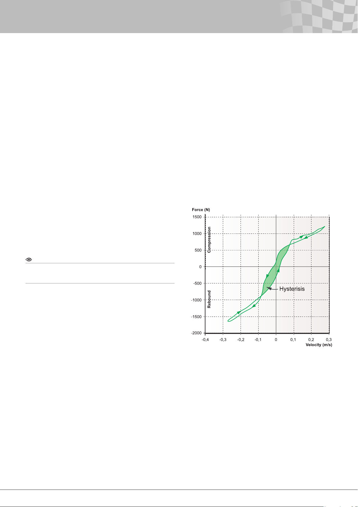
always a difference in ascending (acceleration) and descending
(deceleration) parts of the curve around zero velocity. We normally
refer to this area as hysteresis. At constant velocity or peak force
measurements, the hysteresis can’t be detected. Technically, the
term hysteresis is related to energy losses, but here we are actually
storing energy as the damper acts like a spring.
Hysteresis is actually ex in the damper system. The ex delays
pressure rise and pressure drop. Hysteresis affects the performance
of the damper. Generally, a minimum of ex is desired. Especially
where there are very short damper movements. For example in
single seaters, with very short strokes, you are dependent on quick
damping force build up and if there is any delay, the damper might
change direction before there is any damping at all. Because of this,
hysteresis needs to be kept to a minimum.
How much the delay affects the damping curve is very much
related to the stroke and frequency in the test. When keeping the
maximum velocity constant and varying the frequency and stroke,
it is very obvious that with a short stroke and a high frequency the
hysteresis deforms the damping curve more than long stroke and
low frequency.
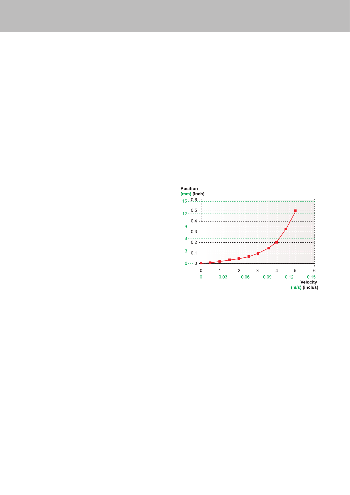
In the graph (gure 8.2), the relation between displacement and
velocity is shown for a peak velocity of 5 ips (0.127 m/s) and a
frequency of 2 Hz.
In a graph illustrating damping forces, the hysteresis changes the
damping curve in a similar way as a more open bleed would do
– both delay the damping force build up when using a sine input.
The force drop from a more open bleed depends on the actual
velocity, while the force drop due to increased hysteresis depends
on the stoke. The setting and the hysteresis affect each other. The
hysteresis increases at increased damping.
If only the compression acceleration and the rebound
deceleration are illustrated, you don’t see the amount of hysteresis.
Therefore, it is easy to believe the bleed is more open when it
actually is due to the hysteresis. There have been situations
when teams have used the dampers with a low speed adjuster
set to almost fully closed position. As the damping curve nose at
continuously measurement still doesn’t go vertical, the teams have
asked for a different adjustment range of the low speed adjusters to
put the actual clicker setting more in the middle of the range. Here,
they have been misled by the hysteresis.
Note!
The displacement at lower velocities is very small. Because of this, still
with very little flex in the damper, the hysteresis in a dynamometer graph
can easily be seen.
Figure 8.1
Damping force during a complete sine‑wave cycle illustrating hysteresis.
Due to the low hysteresis of the TTX40/ TTX46 MT, some oil has been
replaced with air to get a better illustration of hysteresis.
22
Page 24
24
8 - Hysteresis
Due to the low amount of hysteresis of the TTX40/TTX46 MT
compared to other dampers, this should be less of a problem.
Damper ex can be classied into three different groups: ex of
damper parts, ex due to damper oil compressibility, and ex
of gas present in the oil (dissolved or bubbles). The ex of the
damper parts is fully elastic and linear. The compressibility of the
oil itself is not linear. Some hysteresis comes from the compression
and expansion of gases in the oil. Gas bubbles in the oil will be
compressed in a very progressive way and will act almost like a
slack in the system. Dissolved gas in the oil is a result of different
factors. Air enters the damper during the lling procedure and
some air is already dissolved in the oil when it is delivered. By
using a vacuum lling machine, the amount of air in the oil can be
minimised. With a vacuum machine there is no risk of trapping air in
the damper.
The oil used for lling the damper has been under low pressure
for some time before it enters the damper. This removes air
dissolved in the oil. But even without air, there will be gas bubbles
at low pressures. Oil contains different additives that boil at different
pressures/temperatures. At low pressure, those additives change to
a gaseous form which creates bubbles. See chapter “Cavitation” for
more information.
The amount of hysteresis for a certain damping force can be very
different depending on the size of the piston (pressure area) and the
volume of oil that is pressurised. The larger the piston is, the easier
it will be to reduce the hysteresis. This is explained by the formula
F = p • A. F is the force, p is the pressure and A is the pressurised
area. For a specied damping force (F) a smaller area (A) will lead to
a higher pressure (p). The higher pressure will make the damper ex
more. This will cause more hysteresis.
On conventional dampers where the gas reservoir is connected
to the compression side, (not on the TTX40/TTX46 MT), the piston
rod acts as a small diameter piston sending oil to the valve in the
reservoir. Because the effective pressure area is very small and
the total oil volume is large, there will be a lot of hysteresis from
this portion of the damping force compared to the damping force
produced by the main piston.
On all dampers where the internal pressure of the damper pushes
the piston rod out of the damper body, a “hysteresis effect” might
be seen on the dynamometer graph. This is not the case with the
TTX40/TTX46 MT. How much of this “hysteresis effect” that will
be seen depends on how well the dynamometer compensates for
the gas force. The reason for this is that on a conventional damper
the static piston rod force varies depending on the position of the
piston rod.
The more compressed the damper is, the higher the internal
pressure will become due to the gas volume being compressed.
For example, if the gas force compensation only reduces the
compression damping and increases the rebound damping with the
static piston rod force measured when the damper is at maximum
length in the dynamometer, the compensation will not be enough
when the damper is more compressed. This difference can be
mistaken for hysteresis. Good gas force compensation will avoid
this problem.
Figure 8.2
Stroke‑velocity relation in a typical dynamometer run. Peak velocity
5 ips (0.127 m/s) and frequency 2 Hz.
23
Page 25
9 - Cavitation
Cavitation is a word used a lot in the pump and damper industry
for describing the phenomenon when gas bubbles are produced
in uids at pressure drops. The gas comes from both the uid that
has changed its state from uid to gas and from air that had been
dissolved in the uid. Cavitation also includes the collapse of the
gas bubbles when the pressure increases and the gas returns to
liquid form.
In conventional dampers, cavitation very often occurs on the
rebound side of the piston. If no reservoir valve is used the damping
force mainly comes from a pressure drop on the rebound side. Here
the set gas pressure has to be high enough to allow a pressure
drop on the rebound side without letting it get too low. By using a
reservoir valve the pressure doesn’t have to drop as much on the
rebound side as there also will be some increased pressure on the
compression side due to the reservoir valve. However, if the piston
rod is extended near full rebound, the volume on the rebound
side will be small and the pressure will drop very quickly, so some
cavitation will still occur.
Cavitation in dampers should always be prevented. Cavitation
can cause serious malfunction, reduced performance and damage
the damper.
Absolute pressure, temperature and type of uid are factors that
affect the risk of cavitation. Normally, an absolute pressure drop
below 0.7-0.8 bar (10-12 psi) cause cavitation. For your information:
The absolute pressure in the atmosphere is close to 1 bar (15 psi) at
sea level altitude. High piston accelerations will increase the risk of
cavitation as pressure changes do not immediately effect the entire
volume of oil due to delays in the pressure distribution in the uid.
These different pressures in the same volume of oil are sometimes
called “dynamic pressures”.
As cavitation is a state change from uid to gas, compare boiling
of water, an increased temperature increases the risk for cavitation.
However in damper applications the inuence from temperature
variations is normally relatively small compared to the inuence
from pressure variations.
In non-TTX type dampers, pressure drops are found at the
backside of the main piston and at the outlet of the valves. If the
volume of uid where the pressure drop happens is pressurised
high enough, the produced gas bubbles caused by delays in the
pressure distribution will disappear right away. As these small
bubbles only occur very locally in direct proximity of the piston/
valves this phenomenon is sometimes called “local cavitation”.
However, cavitation normally refers to conditions where the
pressure is low enough to make the small gas bubbles combine
to large volumes of gas. If these volumes of gas pass through the
valves instead of damper uid, the damping will go away.
When the gas bubbles are exposed to higher pressure, they
will implode. These implosions could cause damage to damper,
so called cavitation pitting. Often sounds from the implosions can
be noticed as a hissing or gurgling sound. As most dampers use
shimmed main pistons, damage from cavitation is normally found
at the outlet ports of the pistons. The damage is very dependent on
the geometry of the piston.
In a conventional damper, the cavitation starts during the
compression strokes. If the absolute pressure (see below) on the
rebound side drops too much during a compression stroke, gas
bubbles will occur. This leads to a stop in pressure drop on the
rebound side. The volume increases as the oil changes from uid to
gas and oil from the compression side is dumped into the reservoir.
Any additional damping force will come from increased pressure on
the compression side. On the following rebound stroke, there will
be a lack of oil on the rebound side and this will lead to a delay in
the rebound damping force build up.
Most conventional dampers have some type of reservoir valve.
This valve is often referred to as a compression valve, but the main
purpose of this valve is to improve damper response and reduce
the risk of cavitation.
By adding a restriction in the reservoir, the absolute pressure
on the compression side will be higher for a specic compression
damping force. This means that the pressure on the rebound
side does not have to drop as far to achieve the same pressure
differential across the valve. This shortened pressure drop allows
that differential to happen in less time, which equals response time,
and also keeps the rebound pressure away from the cavitation
limits. This may decrease the risk of cavitation, but it adds
hysteresis to the damper.
In a conventional damper with no reservoir valves, the available
damping force before cavitation can be estimated from the formula
below.
F
= p
max comp
p
= reservoir gas pressure
reservoir
(not absolute pressure)
A
= area of the rebound side of the main piston
rebound
(piston area minus rod area).
Always try to stay with the recommended gas pressure and keep
the extra margin against cavitation by adding reservoir damping.
In the TTX, the risk of cavitation is always minimised. Check valves
prevent the pressure from dropping below the set gas pressure.
This results in always having the same good margin for cavitation,
no matter how high the damping forces are. Cavitation in the TTX
can only occur if the oil isn’t pressurised. Even a tiny pressurisation
of 1-2 bar (15–30 psi) is enough. There will be no pressurization of
the oil if
• The reservoir is not pressurized
• There is too little oil in the damper.
If the oil level is to low, the separating piston won’t be pushing on
the uid and can’t add any pressure to the damper uid. The reason
why some pressure has to be added to the damper uid to avoid
cavitation in the TTX is that there will always be small areas with
pressure drops in channels and check valves.
The easiest way to study cavitation in a dynamometer is to
reduce the reservoir gas pressure. Continuous measurement is the
best way to identify cavitation, as the acceleration and deceleration
part of the damping curve separates due to the delayed damping
force build up. In a conventional damper the delay will mainly
be noticed on the rebound side. While in a TTX the delay will
very much less. In a TTX there will be about the same delay on
compression and rebound. Even with constant velocity or peak
velocity measurement, cavitation can sometimes be observed.
However it will be more difcult to know if the loss in damping force
actually is due to cavitation or some other factor.
reservoir
• A
rebound
24
Page 26
26
9 - Cavitation
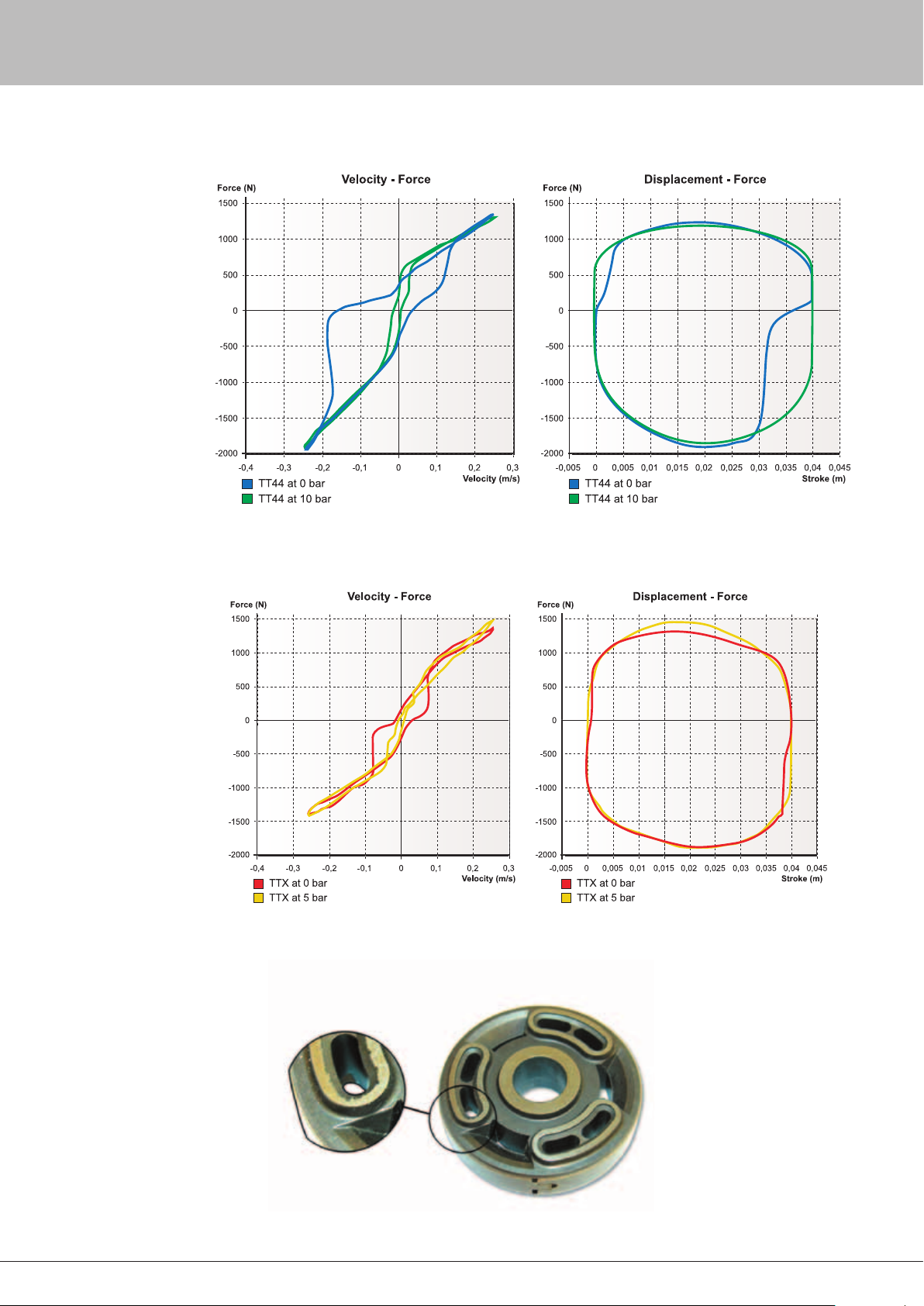
Figure 9.1
Example of cavitation in a TT44 tested at 0 bar of reservoir gas pressure. The curves are produced at continuously
force measurement at a sine wave cycle with peak velocity 0.25 m/s.
Figure 9.2
Example of cavitation in a TTX tested at 0 bar of reservoir gas pressure. The curves are produced at continuously force
measurement at a sine wave cycle with peak velocity 0.25 m/s.
Figure 9.3
Example of cavitation pitting on a shimmed piston.
25
Page 27
For some period in history, damping came mainly from friction.
For example, a leaf spring friction on trucks gives damping. As the
damping characteristics of friction are maximum force at the start of
the movement and normally with little or no relation between friction
force and velocity. Friction doesn’t result in a desired damping
characteristic for a vehicle. The level of friction is also hard to
control. As racing teams always try to optimise everything to gain
performance, the levels of friction can not be neglected.
It is normally hard to quantify the level of friction in the
suspension as it depends on the loads. When it comes to the
dampers, the spring element used is a determining factor. Coil
over springs always cause bending forces to the dampers, as
the springs are not perfect. Here the main friction comes from
the bushings. The design of the TTX40/TTX46 MT will guarantee
minimum friction forces when subjected to side loads.
There are always some variations in friction between individual
dampers. After the dampers have been run in, the friction will be
reduced. Without side loads, the friction levels of a TTX40 could
be expected to be in the region of about 15 - 17 N in sliding
friction and about 22 - 24 N in starting friction. One reason for
these low values is the low gas pressure. Another reason is that
the separating piston doesn’t move as the piston rod displaces oil.
Therefore, there is no friction from the separating piston. If side
loads are added, it is hard to give some exact numbers of how the
TTX40/TTX46 MT perform friction wise compared to for example a
TT40, as is very much depends on the spring used and the position
of the piston rod, but a reduction of friction with about 50% can
easily be found.
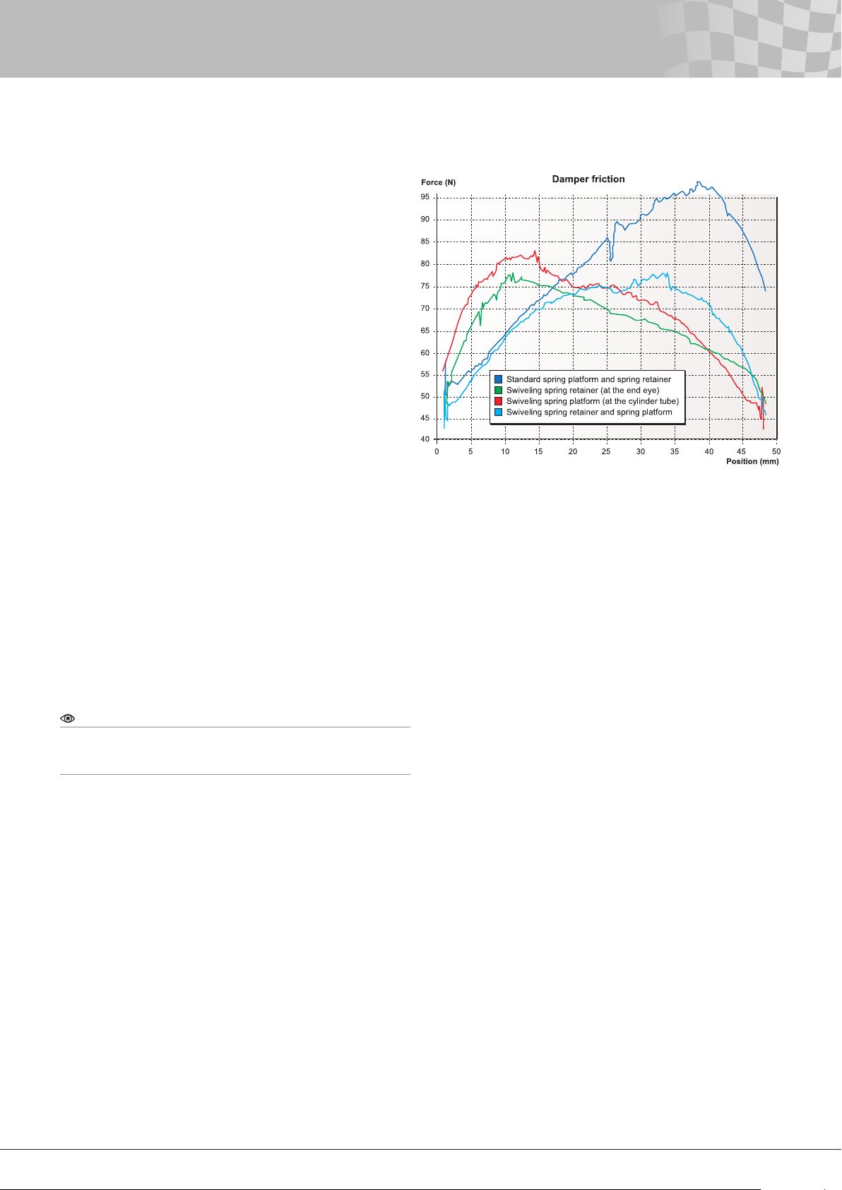
Many times but not always, a swivelling spring retainer and/or
spring platform reduce the friction from side loads caused by coil
springs. In the gure below shows how the friction force varies over
the stroke in a TT44 with different combinations of spring retainers
and spring platforms. The best combination depends on the
position of the piston.
10 - Friction Levels
Figure 10.1
Damper friction verses stroke in a TT44.
The higher the position number is, the more
compressed the damper is.
Note!
The figure here is only for illustrating the trends for a non through
rod damper. The numbers are only true for this particular hardware
combination.
26
Page 28
28
11 - Temperature Stability
In all dampers, the damping force changes due to temperature
variations. As the viscosity drops when the temperature rises, the
damping force will drop unless there is some “compensation”.
The word fading is often used for this loss of damping. The
compensation is normally done by using materials in the bleed
needle and housing, so the opening of the bleed path is reduced
as the temperature goes up. An enclosed volume of uid can also
be used to push the needle closer to the seat. The lengths of the
two parts have to be correct to get an acceptable compensation.
However the compensation can never be perfect and any
overcompensation is objectionable.
How much focus there is on fading varies. On most applications,
the temperature rapidly reaches a constant operating temperature.
In single seaters, there is generally a fairly low amount of energy
absorbed by the dampers. Therefore, the temperatures are normally
very stable – in the front they stay low and in the rear they are
kept high by the engine. See the chapter Temperature range for
recommended temperatures. In applications were a lot of energy is
absorbed by the dampers, fading might be more of a concern.
The amount of fade will depend on the type of ow through a
valve. Flows are divided in to two different categories – laminar and
turbulent. In general, laminar ow occurs where the area change
is gradual and the restriction is extended in length. Turbulent
ow results from an abrupt area change. Also, the velocity of the
uid moving through the valve has an inuence on the type of
ow. Increased velocity increases the amount of turbulent ow.
At laminar ow, the restriction depends on the viscosity, while
turbulent ow is not as sensitive to viscosity changes.
The drop in damping force is not linear with respect to
temperature and depends on the uid used. The Öhlins 309 oil for
instance drops little in viscosity above 50ºC.
It is very hard to give correct values on how much fading there
is in a damper as there are huge variations, both in force and in
percentage of force, due to settings and velocity. The settings
include both hardware and how the adjusters are set. Expressed as
percentage of drop in damping force, fading will always go down as
the velocity increases. In general, compared to a TT44, the TTX40/
TTX46 MT fades more at lower damper velocities while the TT44
drops more at higher velocities.
Note!
For simulations, keep in mind that the actual damping force you have
on the car might be lower than what the dynamometer testing at
room temperature indicates. For this reason dynamometer testing
for this purpose should be done at operating temperature. When
only comparing settings, dynamometer testing can be made at room
temperature if it is always done this way.
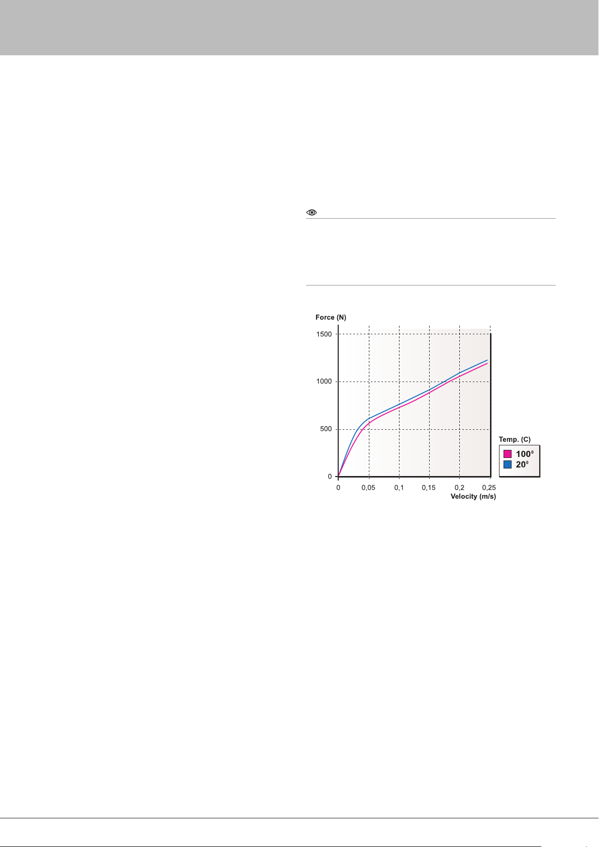
Figure 11.1
Example on how the damping force can drop in a TTX40 if the
temperate raised from 20º C to 100º C.
27
Page 29
By Bruce Burness
Historically, dampers were asked only to provide a comfortable ride. If
you were lucky, driver controllability was enhanced at the same time.
With the advent of ground effect aerodynamics in the late seventies,
racing engineers discovered that damper settings are a valuable tool
for optimising “aero” effects. At the same time, the tire companies
found they needed to redesign their tires to take advantage of the
downforce created by the new ground effect aerodynamics. The
mechanical grip of these new tires also turned out to be extremely
sensitive to damper settings. These developments doubled the
number of duties required of dampers of today. The priority list today
for racing damper functions is “aero” management, mechanical grip,
tire wear, driver controllability and ride comfort. Dampers have a
powerful inuence on the performance of your car.
These ve damper functions are all interrelated but at the same
time optimising one of these functions can sabotage another. A
compromise between function goals is many times unavoidable.
Finding the most effective compromise is the overall goal and will
pay dividends on the racetrack.
Comfort, grip and control
These ve goals are so tightly interwoven that most of the time it is
very difcult to make a damping change and then properly assign
the performance gain or loss to the correct category. For example,
let us say you have added some extra compression damping to the
front dampers and now the front tires have gained grip. The question
is did we create pure mechanical grip from the tires or is the gain
from improved aerodynamics or from better dynamic fore/aft pitch
control or possibly a higher dynamic ride height or centre of gravity
which could also change dynamic roll centres. It is not essential to
know the exact cause and effect, but it is possible through a cleverly
planned sequence of subsequent tests to better isolate the gain
and assign it to the correct category. If this is achieved, the focus of
further testing will be more on target and the possibility of a wayward
theory will be minimised.
All this may sound too hypothetical but rest assured if you
optimise the aerodynamic potential without compromising the grip
and then nd the mechanical balance by adjusting the springs,
sway-bars, etc. the driver controllability will most likely be there
automatically. The ride comfort may be compromised but do not be
too concerned. Even though Öhlins dampers generally produce an
improved ride quality, we have found that damper settings that give
too much comfort cannot provide optimum grip or controllability.
Aerodynamic management
In this ground effect age, dampers can maximise the amount of
downforce generated by the underside of the car by assisting
in maintaining a constant air gap between the underside and the
ground. Today we have basically two types of formula car ground
effect congurations, tunnels and flat bottoms. With both types the
clearance between the underside and the ground is very critical.
Generally there is a ride height ”sweet spot” that is favourable for
generating high downforce with a minimum of ”aero” drag. The
problem is that this ”sweet spot” is very close to the ground. Good
damper settings will keep the car at this ideal ride height a higher
percentage of the time through most dynamic conditions without
allowing the underside to contact the ground (bottoming).
With both tunnel and at bottom cars the centre of the downforce
is found where the geometry of the underside comes closest to the
ground. With either type of car the centre of downforce migrates
with any change in pitch angle in relation to the ground caused by
braking, cornering or acceleration.
12 - Damper Functions
This migration of the centre of downforce alters the handling
balance by increasing the downforce towards the direction of
migration and reducing the downforce away from the migration.
Therefore, added tire grip will occur at the end of the car that
moves closer to the ground.
Tunnel cars have far less downforce migration than at bottom
cars because the contour of the tunnel is curved in the shape of
a venturi with a raised entry that curves down to a short at area
followed by a long, slowly enlarging exit. Tunnels are generally
positioned near the vehicle centre of gravity. The tunnel at part is
in the closest proximity to the ground and that is where the centre
of downforce occurs. When the car pitches fore or aft this part of
the tunnel primarily rocks back and forth and does not raise or
lower signicantly. Tunnels minimise downforce migration.
Flat bottom with diffusers
On the other hand, at bottom cars with diffusers can have the
downforce migrate from just ahead of the diffuser at the back all
the way to the tip of the nose under braking. For cars with raised
noses the migration will essentially stop where the underside begins
to move away from the ground. Flat bottom cars are much more
sensitive to static and dynamic pitch changes than ground effect
cars. Damper settings for at bottom cars therefore need to be
biased more towards pitch control than the settings for tunnel cars.
Both tunnel and at bottom cars can also benet by keeping
the underside parallel to the ground, side to side, while cornering.
In this case, the downforce migrates from side to side but also
will diminish substantially if the inside of the car raises away from
the ground. For cars that turn only one direction as on an oval,
sometimes higher corner speed can be achieved by increasing the
compression damping and reducing the rebound on the right side
(outside) and the opposite on the left side (inside).
Mechanical grip
Compared to aerodynamics, understanding the dynamics of
tire grip is more elusive and the perceived rules change from one
type of tire to another. It seems tire grip is created when the tire
is pressed into the track surface enough to cause the rubber to
interlock with the grain of the pavement. Not enough compression
damping allows the tire to move freer and ride up on top of the
pavement grain, metaphorically similar to “dry aquaplaning”. As the
compression damping is increased, the tire will interlock with the
pavement and grip will increase.
If the damping is further increased incrementally, eventually
the grip will stop improving and begin to go down. This is mainly
caused by too much pressure from the suspension that overheats
the tire or compresses it too much, giving unduly high tire load
variations. Keep in mind that the suspension pressure the tire
feels is the sum of the compression damping, the spring rate, the
sway-bar rate and possibly the torsional rigidity of the chassis.
If the pressure sum seems to be optimised for grip but for other
reasons it is indicated that one component of the sum needs to be
increased, another component may need to be reduced.
For instance, a higher spring rate may be necessary to reduce
fore and aft pitching. In order to make the stiffer spring work
properly, the compression damping may need to be reduced. In
another case, one car might have less torsional stiffness in its
chassis than another. To compensate for this, the car with lower
chassis stiffness will require more compression damping to make
the suspension pressure sum high enough. An indicator of too
much suspension pressure is controllable sliding at all speeds and
all phases throughout the turns (at sliding).
28
Page 30
30
12 - Damper Functions
Grip and rebound damping
Grip in relation to rebound damping works in a slightly different
manner. Rebound damping only occurs after there has been
some compression of the damper and spring. The pavement grain
constantly causes small wheel movements of the suspension
system. The rebound damping controls the expansion in these
small displacements. If the rebound damping is excessive, the
expansion will be too slow leading to a loss of grip. This type of grip
loss will be particularly noticeable in rear tire forward traction with
the application of power. Cornering grip will not be as dramatically
effected as forward traction.
If a lot of rebound damping is used the suspension will be
dynamically pumped down which can improve the aerodynamic
downforce. If there is enough ”aero” gain it can more than
offset any loss of grip due to slow rebound recovery. When this
approach is used compression damping is generally reduced at
the same time to help the pumping down. We have seen success
with this approach, but today most teams are pursuing the high
compression, low rebound technique with even better results.
Both philosophies have their place. It seems that in the classes
where the downforce potential is much less, the proportion
between compression and rebound damping leans towards less
compression and more rebound damping.
Driver controllability
In most cases vehicle stability will be quite acceptable when
the damper has been adjusted for optimum “aero” and grip
management. Sometimes “aero” and grip need to be slightly
compromised in order to adapt to the style of different drivers. In
the nal analysis a car that is more driver friendly will prevail over a
car with ultimate grip that is also nervous.
Tire wear
Sometimes settings that are good for qualifying can be too hard
on tires after a lot of laps. Our experience suggests slightly more
compliant damper settings for the race than those used during
qualifying.
Ride comfort
One nal word about ride comfort. Harshness is either from
a suspension that is too stiff to comply with bumps or from a
suspension that shakes because of inadequate damping. Deciding
which condition exists in your car plus a review of your damper
settings can guide you in solving harshness problems.
29
Page 31
13 - Damping Guidelines
It is not our intention in this chapter to cover all questions about
how to nd a good damper set-up. However, we offer some basic
rules to help you set up the car. The rst time the TTX40/TTX46 MT
is installed on the vehicle our recommendation is to match the
damping curves previously used. However, as the TTX40/TTX46 MT
will have at least as quick damping force build up as the damper
you are replacing, you might have to lower the damping force on
the TTX40/TTX46 MT to nd a better set-up.
If there is no history when it comes to damping forces, some
calculations, simulations or shake rig testing might be needed to
nd the correct amount of damping. If “aero” isn’t taken in account,
there will be no information about the distribution compression
to rebound damping. Also, the damping curves may need to be
reshaped from the maximum grip level to achieve an acceptable
vehicle handling. Here experience is extremely useful.
In general, our recommendation is to start with linear damping
curves and add knee if necessary.
When comparing damping curves, keep in mind that the motion
ratio must be the same. The damping forces at a different motion
ratio could be estimated by scaling the forces with the square of
the quotient of the motion ratios. If the damping curves are not
very linear, you have to do a more proper calculation by scaling
both the forces and velocity with the quotient. One of them should
be multiplied with the quotient the other divided. See the end of
this chapter for some more detailed information. Having intimate
knowledge of your damper mounting geometry is the key to
predicting the proper amount of damping forces.
If your racecar has handling problems, determine rst if it is
damper related or not. Because dampers have proved to have such
a profound inuence on handling, some race engineers are in the
habit of tuning the dampers before making “aero” or mechanical
adjustments. As damper manufacturers, we are attered, but
there are limits to the problems that can be solved by damping
adjustments. If a problem can be improved by “aero” or mechanical
changes, it is wise to make those changes rst.
To make improvements, it is important to understand the function
of the dampers. Then through testing, learn how the dampers
inuence the handling of your car. When making adjustments,
keep notes, make adjustments one at a time and in small steps.
Always pay attention to changes in conditions like tire wear, track
temperatures, time of day, etc. At the end of the test session, go
back, if possible, to the starting set-up to double check that an
improvement has actually been achieved.
We recommend limiting changing of the low speed adjusters to
steps of no more than 6 to 7 clicks at the time. Too large a change
can jump right over the optimum setting and sometimes result in
similar handling as the original setting. We normally recommend
changes of 3 to 4 clicks. When you are near the optimum setting
the driver can notice such a little change as 1 or 2 clicks. When
both compression and rebound are near optimum a nal adjustment
might require a trade of one less rebound click for one more
compression click or the reverse.
A logical reason for opening only the compression low speed
adjuster could be a desire to reduce harshness, to slow down turnin, or to search for more mechanical grip. The limits to how far the
low speed adjusters can be opened are instability, bottoming, lazy
turn-in, not enough roll support, braking problems or loss of grip.
Opening the low speed rebound adjuster usually results in more
grip especially in the rear during power-down conditions.
As the low speed adjusters are changed, the knee will occur at
a different velocity. This affects the high speed forces. The more
slope there is on the high speed, the more the high speed will be
affected. This can be compensated by changing the high speed
adjusters to raise or lower the knee.
Raising the knee (mainly on compression) can result in more
support. Raising the knee can also be an effective way to control
the underside rake angle, in either the front or rear. Lowering the
knee can reduce harshness.
The more pronounced knee you have the more feedback the
driver will get. There is often a trade off between feedback and
grip/traction.
Reducing the compression slope might be called for on bumpy
street courses if your car has difculty absorbing bumps causing
harshness. You might want to increase the compression slope if the
car bottoms easily or if roll support seems inadequate. This could
also be advantageous on bumpy circuits where bumps cause big
chassis movements.
Also, if you determine the knee needs to be reduced, increasing
the slope at the same time is sometimes a good idea. The converse
is also true.
To compensate for motion ratio changes, both high and low
speed have to be changed.
It is not easy to have some general rules about in what range
the adjusters should be set, as the needs can be very different
depending on the vehicle. However for race cars with damper/
wheel bell crank (rocker) ratios of around 1.0/1.0, the low speed
compression (LSC) very often ends up at a clicker position in
the range of 6 to 14. The corresponding range for the low speed
rebound (LSR) is 15 to 25.
If your bell crank ratio moves the damper slower than the wheel,
the clickers will need to be set to lower numbers to give more low
speed damping. The reason is the wheel has mechanical leverage
over the damper and the forces from the damper will end up less
effective at the wheel. In addition, the leverage also causes the
damper piston speed to be lower. Thus the original damping must
be multiplied by the change factor and then the new damping
force must be moved to a lower piston speed this time dividing the
speed by the same factor. To compensate for the leverage changes,
tighten the low speed adjuster and add preload with the high speed
adjuster.
Conversely, if your bell crank ratio moves the damper faster than
the wheel the adjusters need to be set to higher numbers to give
less damping and the damping change factor now needs to divide
the original damping and multiply the piston speed.
30
Page 32
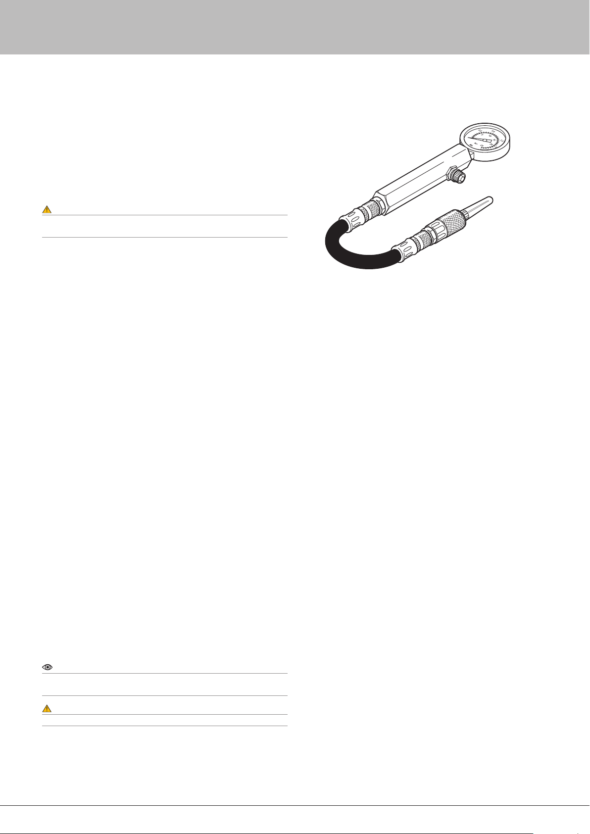
32
14 - Gas Pressure
A good rule is to stay with the recommended pressure. For the
TTX40/TTX46 MT this pressure is 5 bar (75 psi).In the TTX40/TTX46
MT, different gas pressures have no inuence of the damper
characteristics. For instance a range of 2 to 10 bar can be used
with no inuence on the characteristics. Even going higher than
10 bar will not effect the damping characteristics but it will exert
unnecessary forces on the damper parts. Be aware that at 0 bar,
there will be cavitation.
Warning!
Never run the TTX40/TTX46 MT damper at higher gas pressure than
10 bar.
Always pressurise the damper at room temperature.Use nitrogen
gas only. It is an inammable gas with no effect on the material in
the gas reservoir.
See section Using the gas filling device in the work shop manual
for how to pressurise and depressurise the damper. If there are any
doubts, please contact an Öhlins distributor.
Figure 14.0
Gas filling device
15 - Temperature Range
The working environment for the damper is important to its
function and life. You should always pay attention to the damper
temperature. Low temperature is normally not a problem with the
TTX40/TTX46 MT damper. The problem is high temperatures.
Some heat is generated by the damping energy, but most of the
heat comes from being in close proximity to engine or brake parts.
Try to keep the temperature below 90°C (approx. 200°F). If the
damper runs hotter than 120°C (approx. 250°F), try to vent some
fresh air to the damper. Heat shields may be necessary. Naca
ducts in the engine cover also help cooling. If your vehicle has the
exhaust system on one side only, a larger naca duct on that side
can equalise the temperature of both dampers.
The gas volume is not stroke dependent, but remember that the
gas volume will decrease as the oil expands from the temperature
change.
Note!
Many times the temperature variation is the problem, not the
temperature itself.
Warning!
Always pay attention to the position of the separating piston.
See section Revalving in the Work shop manual for information.
teams put them in a can of cold water. This is not recommended.
down. Trapped air will help prevent water from reaching the internal
piston rod. Also, spray some WD40 or similar into the holes of the
top eye to protect the piston rod. Otherwise, the end of the piston
rod will rust. Make sure the rust preventive being used doesn’t
cause damage to rubber.
To cool down the dampers, when they come off the car, some
However if this happens, put the shock in with the cylinder head
31
Page 33
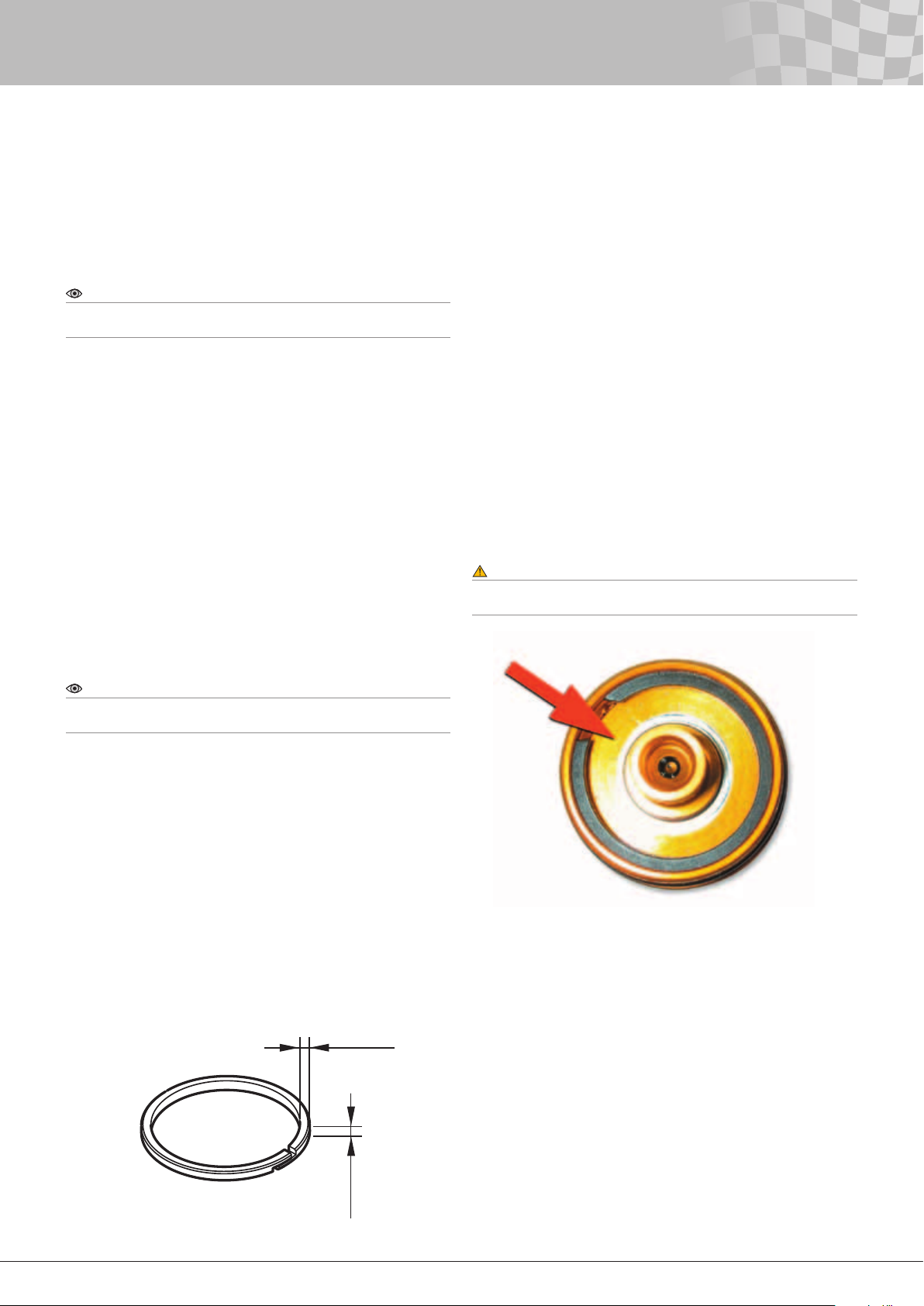
16 - Routine Maintenance
It is hard to give recommendations about servicing dampers as the
conditions vary a lot. For example, during hot and dirty conditions
the maintenance has to be done more frequently.
An example of a recommended inspection and maintenance
schedule for a Champ car team starting to run TTX40 dampers is as
follows.
Note!
Depending on the results of the inspections below, the time between
the inspections can be changed.
Every race weekend
• Measure the position of the separating piston. This should be
done several times during a race weekend. On the TTX40 this is
a very quick operation. See section Adjusting the oil level in the
Work shop manual.
• Look for oil leakage. By keeping the damper clean and dry, any
leakage will be easy to detect. If oil is leaking from the X-ring
seal repeatedly, replace X-ring and inspect the piston rod for
imperfections on its surface.
• Inspect the dampers for external wear or damage.
• Check the spherical bearings regularly for excessive play. On
installations where the spring is not of coil over type, a gap is
more critical as the bearings will see loads in both directions.
Every third to fifth race weekend
• Inspect the piston ring for wear occasionally by measuring the
height and width of the piston ring.
Every tenth to fifteenth race weekend
• Inspect the condition of the two piston rod bushings. Even
if some of the PTFE (grey colour) covering the surface of the
bushings is gone, they still perform ne. If all of the PTFE is
gone, the bushings should be replaced. No Loctite is needed. If
assistance is needed, contact Öhlins distributors.
It is hard to give some general recommendations when to change
the oil as the conditions vary greatly. If the oil has changed colour
and smells bad the oil should be changed. In hot conditions, in the
region of 90°C (approx. 200°F) begin to inspect the oil after about
1500 km (approx. 1000 miles). Only use Öhlins damper uid 309.
If any o-rings need to be replaced, always apply Öhlins red grease
(part no. 00146-01) to the new o-rings. The same thing applies to
the threads where no Loctite is used.
A dynamometer is a good tool to nd failures in the damper.
Therefore, we recommend doing regular dynamometer testing. For
example leakage, check valve problems, etc, can be detected. See
chapter Damping force measurement for more information.
At least once every season, we recommend complete
disassembly of the damper for visual examination. Ask your Öhlins
distributor for help or advice if needed.
Warning!
Make sure the chemical substance used for cleaning the dampers does
not harm rubber and plastic.
Note!
The piston ring of the TTX40 is a seal and not a bushing and it does not
take any side loads so ware should be minimal.
See the gure below for smallest accepted dimensions of the piston
ring. Replace if necessary. See section Rebuilding the damper in
the Work shop manaul for information about how to remove the
piston ring.
• Check the condition of the inside of the inner tubes. See
section Rebuilding the damper in the Work shop manual for
information about how to remove the inner tube.
• Examine the sealing surfaces of the valves and the check
valves. These consist of the valves, the seats and the nose
shims. The sealing surface of the nose shims will become
polished, but as long as no signicant wear is noticed, they won’t
have to be replaced. The same thing is true for the check valve
shims. See section Revalving in the Work shop manaual.
• Examine the surface of the needle housing where the coil
springs is seated.
2.2 mm
Figure 16.2
Area to inspect at the needle housings.
Figure 16.1
Smallest accepted dimensions of the TTX40 damper piston band.
2.64 mm
32
Page 34
34
17 - Actions after Crash or Fire
The damage to a car involved in a crash very often gives a good
idea if the dampers are intact or not. If you suspect that there is a
risk that something has happened to a damper, you should remove
the damper from the car for closer inspection.
First, check for leakage and new external marks or cuts on the
damper you haven’t seen before. If you nd something, you have to
inspect the damper carefully to determine what is damaged.
Slowly compress the damper by hand and pay attention for
variations in friction. Increased friction is often an indication of a
bent piston rod. The straightness of the piston rod should always
be checked and be within 0.05 mm (0.002 inch). If possible, make
a dynamometer test to ensure that the damping forces reproduce
correctly.
A crash sometimes results in cracks in the damper materials.
The cracks may be hard to detect with the bare eyes, so Öhlins
always recommends making a magnaux inspection on the parts
that could be damaged. If no special indications of damage can
be seen, these parts should always be checked: top eye, cylinder
head, outer tube, piston rod and end eye.
If the dampers have been in an area of re, the heat might
have had an effect on the material. The rubber seals are the most
sensitive parts and should always be replaced. Also, check the
plastic parts like spacers, bushings etc.
When opening a damper that has been in a re, ensure the
ventilation is good and avoid getting the oil on your skin as it might
be harmful.
Even with no visible damage to the metal parts, the heat might have
affected them and the strength of the materials can be reduced.
By measuring the hardness of the materials, you can nd out. If the
hardness has gone down, the parts should be replaced.
If the dampers have been at a very high temperature, not only
in a re but anything that may cause unusually high temperatures,
there is a risk that the separating piston will bottom out. If so,
the cylinder head could start to deform at the circlip holding the
reservoir end cap. Therefore inspect the top of the cylinder head
carefully.
If in doubt, always replace the parts.
Note!
Glued parts can come loose.
33
Page 35
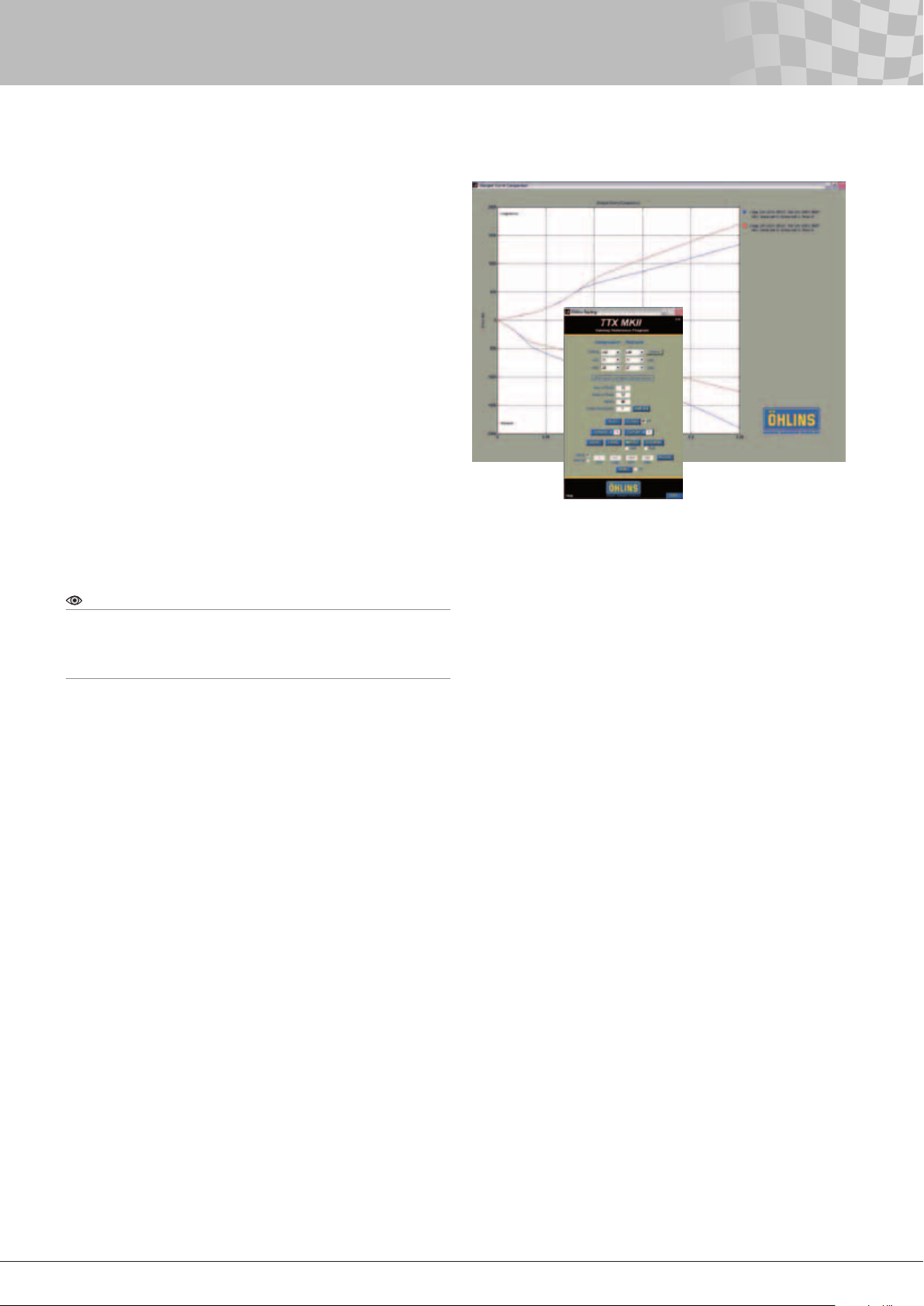
18 - Valving Reference Program
One of the advantages with the TTX40/TTX46 MT is the ability
to use the VRP (Valving Reference Program). It enables you to
research the damping forces without dynamometer testing.
You virtually build your damper in the computer using different
combinations of clicker settings, valves, poppets, nose shims,
shims stacks and valve springs. The program will then present
the Compression and Rebound dynamometer curve for your
specic setting. This will make the work easier and quicker for both
mechanics and engineers. No manual today with valving charts can
cover as big range of combinations of adjustments and settings as
the Öhlins VRP does.
Normally, a lot of dynamometer testing is necessary to nd the
setting that produces the desired damping curve. This results in a
lot of work since usually the hardware has to be changed several
times during this process. With the VRP this is not necessary. The
VRP should be seen as a complement to the dynamometer, not as
a replacement.
The dynamometer is still needed to ensure that the correct
damping forces are achieved. This work will be made much easier
by using the VRP, since comparing the dynamometer forces with
the VRP forces can be done with any combination of valves and
clicker settings desired. The damping forces illustrated in the
VRP have been measured in an Instron dynamometer at constant
velocity.
Figure 18.0
VRP desktop interface.
Note!
If these forces are compared to forces from a dynamometer measuring
the forces continuously (crank dynamometer), there will be some
differences. For best results, use peak velocity measurements on a
crank dynamometer. See chapter Damping force measurement.
Of course it is possible to use nose shim stacks or shim stacks not
covered by the program, but there should be little need for this.
The TTX40/TTX46 MT VRP is free of charge on the Internet at www.
ohlins.com. The TTX40/TTX46 MT VRP is basically self-instructive,
but there is also an text instruction available in the program.
34
Page 36
36
19 - Damper Configuration
The TTX40 damper is available with different strokes. To minimise
the damper length needed for a given stroke, the external and the
internal stroke is the same. The exception is the TTX NE02, TTX
NE04, TTX NH02 and TTX NH04 that has 15 respective 21 mm
external spacers and TTX NH06 and TTX NH08 that has 10 mm
less externa stroke then internal. This is due to that the TTX NH06
and TTX NH08 has a lock nut that is 10 mm higher to increase the
strength of the shaft.
On the TTX NH06 and TTX NH08 it is possible to use the same
nut as the TTX NH01-04 and gain 10 mm stroke, but in the same
time loose some strength. A small difference ensures a well dened
external bottoming. The external stroke is approx. 0.5 mm shorter
than the internal stoke (except TTX NH06 and TTX NH08 with
the higher lock nut, see above). There is also approx. 0.5 mm in
distance between the internal piston rod and the bottom of the top
eye at fully compressed position except for the TTX NE01 and TTX
NH01, where the distance is 3.5 mm.
To ensure a correct assembly of the dampers including
dynamometer testing and still give the customers freedom to
congure their dampers, the dampers are sold without end eyes,
spacers or spring platforms. The TTX46MT comes with upper and
lower spring platforms, sway bar bracket needs to be ordered
separately. We call this unit the “damper unit”.
The TTX40 damper is designed to t 2 inch i.d. springs. Platforms
for 2.25 inch i.d. springs are also available. It is also possible to run
36 mm (1.5 inch) i.d. springs. If so, the spring platform is placed on
the end cap of the cylinder body.
The TTX46MT damper is designed to t 60 mm (2.36”) springs.
Note!
The lock nut for the end eye (part no. 06117‑01/‑03, TTX40 only)
together with the plastic spacer (part no. 05449‑03/‑06, TTX40 only)
covering this nut are installed on the damper unit. A set screw (part no.
05410‑01, 3 pcs together with TTX46MT) for the spring platform also
comes with the damper unit. If bump rubbers will be used, an external
spacer must be used to prevent bump rubber damage caused by the
holes in the end cap (TTX40 only).
See the Spare Parts List for the TTX40 or TTX46MT for
identications of parts. In the Spare Parts Lists you also can nd
some more additional parts. Always make sure that you have the
latest Spare Parts Lists to keep updated with new additional parts.
To get your desired damper configuration pick
• Damper unit (TTX40 or TTX46MT)
• End eye (only TTX40)
• Spacers for spherical bearings (“top hats”) to top eye
and end eye (only TTX40)
• Spring platform (only TTX40)
• Spring retainer (spring platform at end eye) (only TTX40)
• Internal spacers (TTX40 and TTX46MT)
• External spacers (only TTX40)
• Packers (only TTX40)
• Sleeve (for tube protecting) (only TTX40)
• Sway bar bracket (only TTX46MT)
The rubber caps (part no. 05925-01, included in the kits) can be
tted to the valve end caps to protect the adjusters from dirt. The
cylinder tube protecting sleeve (part no. 06140-01, TTX40 only,
not included) is useful when 2 inch i.d. springs are used as there is
a risk of the spring contacting the outer tube. When long springs
are used, this risk increases. The protecting sleeve is installed
with spanner part no.00738-01 together with mounting sleeve part
no. 00737-04. Torque: 30 Nm (22 lbs.ft.). As the torque can’t be
measured, it has to be estimated.
35
Page 37
Figure 19.1
Table with parts needed to complete a TTX40 damper.
19 - Damper Configuration
Damper unit /
Stroke [mm]
TTX NE01 / 48 06136-01 2) 05425-XX 5) 05964-01 (2”) 05441-01 (1.5”) 06132-01 (1 mm) 8) 06130-01 (1 mm) 8) 06131-02 (2 mm) 8)
TTX NH01 / 48 06136-02 2) 05518-XX 5) 05964-02 (2.25”) 05411-01 (2.25”) 06132-02 (2 mm) 8) 06130-02 (2 mm) 8) 06131-03 (3 mm) 8)
TTX NE02 / 56 06136-03 2) 06119-XX 6) 05972-01 (1.5”) 7) 05411-02 (2”) 06132-05 (5 mm) 8) 06130-05 (5 mm) 8) 06231-02 (2 mm) 9)
TTX NH02 / 56 06136-04 2) 05411-03 (2,25”) 4) 06132-10 (10 mm) 8) 06130-10 (10 mm) 8) 06231-03 (3 mm) 9)
TTX NE03 / 68 06136-05 2) 05412-01 (2.25”) 06242-02 (2 mm) 9) 06233-01 (1 mm) 9)
TTX NH03 / 68 06136-06 2) 05965-01 (2”) 06242-05 (5 mm) 9) 06233-02 (2 mm) 9)
TTX NE04 / 80 06136-07 2) 06242-10 (10 mm) 9) 06233-05 (5 mm) 9)
TTX NH04 / 80 06133-01 3) 06233-10 (10 mm) 9)
TTX NE06 / 110 06219-01 2)/4)
TTX NH06 1)/ 100 06219-02 2)/4)
TTX NE08 / 140 06219-03 2)/4)
TTX NH08 1) / 130 06219-04 2)/4)
End eye Bearing
spacers
06219-05 2)/4)
06219-06 2)/4)
06219-07 2)/4)
Spring platform Spring retainer Internal spacers External spacers Packers
Note!
If bump rubbers are to be used on a 36 mm (1.5 inch) spring
configuration, spacer 05449‑xx can be machined down to fit inside the
spring. The internal spacers in the 06132 and 06242 series can be used
as external spacers.
The parts in the table above are not the only ones that can be
ordered, see the Spare Parts List for a complete list. Thus, there is a
freedom to build the damper you need. Even if none of the damper
units can be used without modications, Öhlins recommendation
is to always order a complete damper unit and modify it instead
of ordering all included parts. Pick the unit with the correct tube
length and change top eye and/or external piston rod if needed. As
the internal piston rod matches the tube length, it never has to be
changed unless the tubes are changed.
There could be several different reasons why some parts in a
damper unit have to be changed. For instance, a longer top eye
might be needed to move the cylinder head away from some
interference near the top mount. Another example is, a team
optimising the stroke when using bump rubbers.
1) Dampers with 14 mm piston shaft.
2) Bearing 05536-05 and circlips 05057-04 (2x) have to be included.
3) Bearing 05536-01 and circlips 05057-02 (2x) have to be included.
4) End eye 06219-xx and spring seat 05411-03 used together. Note
that you also need to order circlip 00428-01.
5) For ball joint with 3/8” hole diameter (05536-01).
6) For ball joint with 1/2” hole diameter (05536-05).
7) O-ring 00438-60 has to be included.
8) Used together with dampers with 12 mm shaft
9) Used together with dampers with 14 mm shaft
For additional parts see the Spare Parts list for TTX40/46MT.
36
Page 38
38
19 - Damper Configuration
As a bump rubber will take some of the external stroke away, a
longer piston rod might be needed. When doing this, the length of
the piston rod can be calculated by taking into account the type of
bump rubber being used and the highest acceptable force from the
installed bump rubber. The height of the bump rubber at specied
force can be found from a force-position graph.
All damper units except TTX NE02, TTX NE04, TTX NH02 and
TTX NH04 come without external spacers on the piston rod. The
external piston rod is optimised to match the internal stokes. TTX
NE02, TTX NE04, TTX NH02 and TTX NH04 come with a piston rod
that would give longer external strokes than internal if there are no
external spacers used. This allows the ability to run bump rubbers
without losing any stroke, and results in more room for the spring. If
the last two digits of the external piston rod part number match the
numbers of the damper unit, the external piston rod is optimised to
the stoke of the damper unit.
For example, the TTX NE02 and TTX NH02 needs a 06127-02 (is
delivered with a 06127-12 piston rod) and the TTX NE04 and TTX
NH04 needs a 06127-04 (is delivered with a 06127-14 piston rod)
piston rod to have an external stroke matching the internal stoke.
Except for the external piston rods of TTX NE02/TTX NH02
(06127-12) and TTX NE04/TTX NH04 (06127-14), all top eyes
(06126-XX for TTX NE0X and TTX NH01-04 dampers and 06226-XX
for TTX NH06 and TTX NH08 dampers), internal and external tubes
(06110-XX and 06109-XX), internal (06112-XX for TTX NE0X and
TTX NH01-04 dampers and 06232-XX for TTX NH06 and TTX NH08
dampers) and external piston rods (06127-XX for TTX NE0X and
TTX NH01-04 dampers and 06150-XX for TTX NH06 and TTX NH08
dampers) have numbers that matches their damper unit.
For damper units TTX NE04, TTX NH04, TTX NE06, TTX NH06,
TTX NE08 and TTX NH08 (the damper units with the longest strokes
and therefore the largest volumes of oil), a reservoir end cap
06121-02 with a larger gas volume is used instead of 06121-01.
The stroke of the separating piston will increase by 4.5 mm. If the
separating piston is set so there is 1 mm between the tool 01876XX and the reservoir end cap, the stroke of the separating piston is
5.5 mm with end cap 06121-01 and 10 mm with end cap 06121-02.
However the useable stroke is less than that. The internal pressure
will otherwise be too high. See chapter Checking oil level and
pressurisation in the Work Shop Manual for more information.
The tool 01876-XX needed to check to position of the separating
piston is available in two different versions: 01876-01 and 01876-
02. The 01876-01 is used together with top eye 06126-01, -02 and
-03. 01876-02 is used together with the top eye 06126-04, -06 ,-08,
06226-06 and -08. To position the separating piston, an additional
tool of the 01877-XX series is needed. For each length of the top
eye, a corresponding length of the spacer tool in the 01877 series
is required. The last digit of the spacer part number matches the
last digit of the top eye part number.
For example a 06126-02 top eye uses a 01877-02 spacer tool.
Note that TTX NE06 and TTX NH06 uses tool 01877-26, TTX NE08
and TTX NH08 uses tool 01877-28. Tools 01877-06 and 01877-08
can be used on TTX NE06 and TTX NE08 but not on TTX NH06 and
TTX NH08 due to the bigger outside diameter of the top eyes for
the NH dampers (14 mm piston shafts).
External and internal spacers together with the available lengths
of top eyes, cylinder tubes, piston rods and a large number of
different end eyes, give you plenty of freedom to get the damper
that you are looking for.
Note!
Top eye 06126‑01, ‑02 and ‑03 can only be used with reservoir end
cap 06121‑01 and top eye 06126‑04, ‑05,‑06, ‑08, 06226‑06 and
‑08 can only be used together with the reservoir end cap 06121‑02.
Reservoir end cap 06121‑01 uses pressure indicator 06105‑01 (2x) and
end cap 06121‑02 uses pressure indicator 06105‑02 (2x).
37
Page 39
19 - Damper Configuration
TTX 40
Note!
On the TTX 40 the top eye can be rotated and positioned in any angle
to the cylinder head.
See the Work Shop Manual for information about how to reclock
the top eye. There is also a cross section of the damper, where
parameters needed to do length calculations are dened. A table
gives the different parameter values available. Some parts are
illustrated with dimensions to simplify identication and to help the
customers that may need to make these parts themselves, i.e. a
custom made end eye.
Note!
All dimensions in drawings, tables and formulas are in millimetres.
Note!
The inner tubes are listed here and they must always have the same
number in the last two digits of the part number as the corresponding
outer tuber. For example inner tube 06110‑03 is always used together
with outer tube 06109‑03. The inner tubes are always 16.5 mm shorter
than the corresponding outer tubes.
Formulas to calculate stroke and length follows:
FEL* = A + B + H + D - G - 2.8
*FEL = Fully Extended Length
TTX 46MT
Note!
On the TTX 46MT the gas reservoir can be located either upward or
downward. See the Work Shop Manual for information about how to
change the direction of the gas reservoir.
TTX 40/46MT
Dimensions of some parts
As some teams might want to make custom end eyes and spring
retainers themselves, some key dimensions in the sketches will
make this easier. On the following pages you can nd the most
important drawings and dimensions.
Note!
H in the formula above only refers to end eyes of the 06136 and 06219
series. The fully extended length should be within +‑1 mm.
Internal stroke 1 = B - G - 28.2
Internal stroke 2 = A + B - E - G + 11.3
External stroke = D - F - G - 32.4
Note!
The internal piston rod has to be long enough to seal against the X‑ring.
Formula to calculate the minimum length of the internal piston rod:
ML* = B - G + 13.1
*ML = Minimum length of internal piston rod
38
Page 40
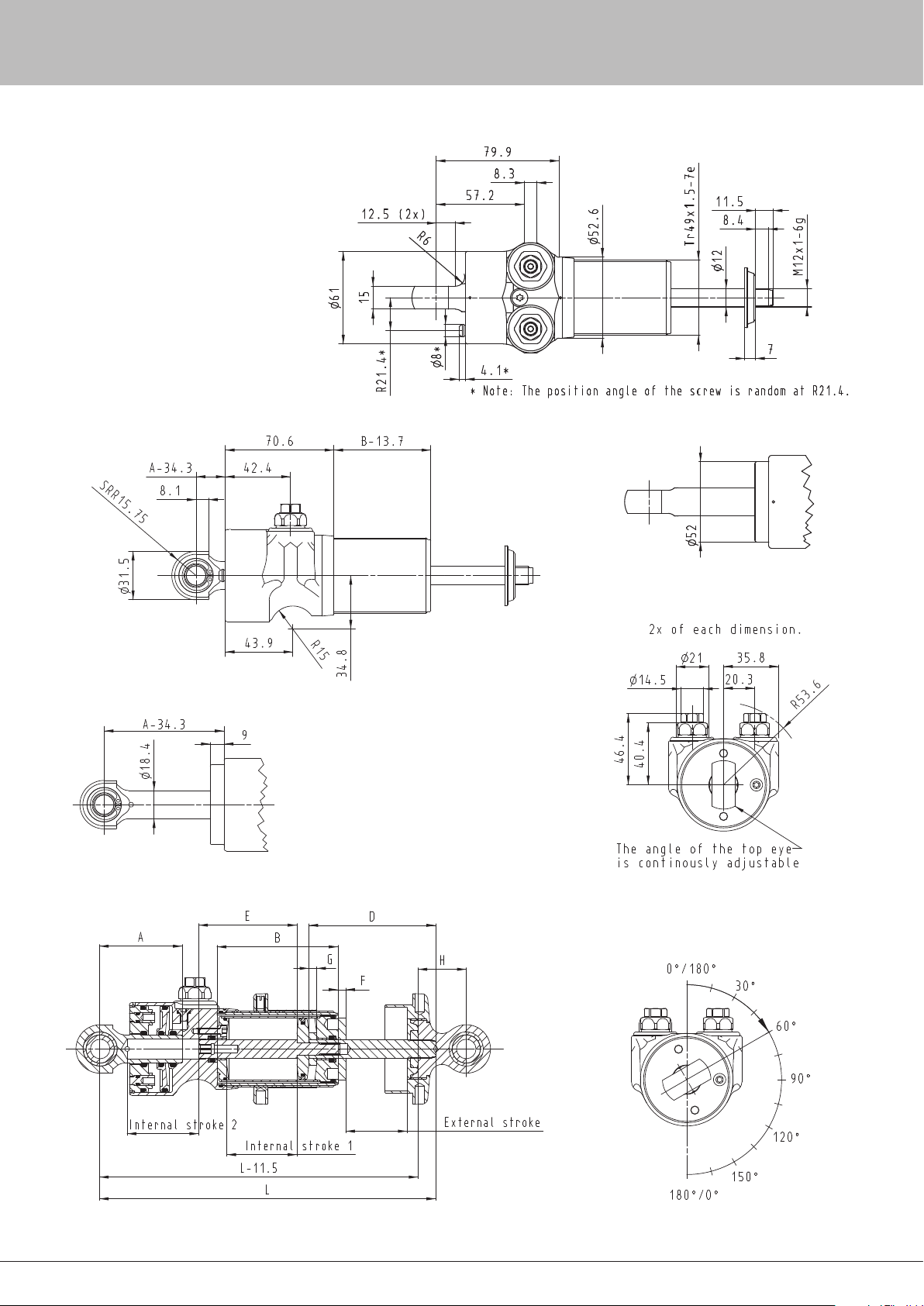
40
20 - Damper Dimensions
TTX NE01, TTX NE02, TTX NE03, TTX NH01, TTX NH02 and TTX NH03
In the figures below are some external dimensions of
the TTX40 damper.
TTX NE01, TTX NE02, TTX NE03, TTX NH01, TTX NH02 and TTX NH03
TTX NE04, TTX NE06, TTX NE08, TTX NH04, TTX NH06 and TTX NH08
Figure 20.2
Side view of a TTX40 damper unit. See the cross section view below for
definition of A and B.
TTX NE04, TTX NE06, TTX NE08, TTX NH04, TTX NH06 and TTX NH08
Figure 20.1
Front view of a TTX40 damper unit.
Figure 20.3
Top view of a TTX40 damper unit.
Figure 20.4
Cross section view of a TTX40 damper unit.
39
Figure 20.5
Definition of clocking angle of TTX40.
Page 41
20 - Damper Dimensions
76.4 06219-06
85.4 06219-07
E Internal piston rod F 06130
rod
122.2 06290-06 4) 58.4 06219-04
152.2 06290-08 4) 67.4 06219-05
172.4 80.2 06290-03 4) 06127-08 1) 40.4 06219-02
172.4 92.2 06290-04 4) 06250-08 2) 49.4 06219-03
Damper External stroke Internal stroke 1 Internal stroke 2 L - 11.5
TTX NE01/TTX NH01 48 48.5 51.5 207.6
TTX NE02/TTX NH02 56 56.5 56.5 243.6
TTX NE03/TTX NH03 68 68.5 68.5 264.6
TTX NE04/TTX NH04 80 80.5 80.5 321.6
TTX NE06/TTX NH06 110/100 110.5 110.5 390.6
TTX NE08/TTX NH08 140/130 140.5 140.5 480.6
Figure 20.6
Table 1 with TTX40 damper unit
information.
TTX NE08 142.3 06126-08 168.7 -08 172.4 06127-08 181.8 06112-08 0 -
TTX NH06 112.3 06226-06 138.7 -06 142.4 06232-06 151.8 06232-06 0 -
TTX NE06 112.3 06126-06 138.7 -06 142.4 06127-06 151.8 06112-06 0 -
TTX NE04/TTX NH04 82.3 06126-04 108.7 -04 133.4 06127-14 121.8 06112-04 21 -01x1 -10x2
TTX NE03/TTX NH03 70.3 06126-03 96.7 -03 100.4 06127-03 109.8 06112-03 0 -
TTX NE02/TTX NH02 58.3 06126-02 84.7 -02 103.4 06127-12 97.8 06112-02 15 -05x1 -10x1
TTX NE01/TTX NH01 53.3 06126-01 76.7 -01 80.4 06127-01 89.8 06112-01 0 -
Damper A Top eye B 06109 D Externa piston
Figure 20.7
Table 2 with TTX 40 damper unit
information. Dimensions in millimetre.
40
A Top eye B Outer tube D I Inner tube External shaft E Internal shaft F External spacer G Internal spacer H End eye
53.3 06126-01 1) 76.7 06109-01 80.4 60.2 06110-01 3) 06127-01 1) 89.8 06112-01 1) 1 06130-01 1) 1 06132-01 1) 31.4 06136-01
58.3 06126-02 1) 84.7 06109-02 88.4 68.2 06110-02 3) 06127-02 1) 97.8 06112-02 1) 2 06130-02 1) 2 06132-02 1) 40.4 06136-02
70.3 06126-03 1) 96.7 06109-03 100.4 80.2 06110-03 3) 06127-03 1) 109.8 06112-03 1) 5 06130-05 1) 5 06132-05 1) 49.4 06136-03
82.3 06126-04 1) 108.7 06109-04 103.4 92.2 06110-04 3) 06127-12 1) 121.8 06112-04 1) 10 06130-10 1) 10 06132-10 1) 58.4 06136-04
TTX NH08 142.3 06226-08 168.7 -08 172.4 06232-08 181.8 06232-08 0 -
112.3 06126-06 1) 138.7 06109-06 112.4 122.2 06110-06 3) 06127-04 1) 151.8 06112-06 1) 1 06233-01 2) 2 06242-02 2) 67.4 06136-05
112.3 06226-06 2) 168.7 06109-08 133.4 152.2 06110-08 3) 06127-14 1) 151.8 06232-06 2*) 2 06233-022) 5 06242-05 2) 76.4 06136-06
142.3 06126-08 1) 142.4 60.2 06290-01 4) 06127-06 1) 181.8 06112-08 1) 5 06233-05 2) 10 06242-10 2) 85.4 06136-07
142.3 06226-08 2) 142.4 68.2 06290-02 4) 06250-06 2) 181.8 06232-08 2*) 10 06233-10 2) 31.4 06219-01
Figure 20.8
Table of the different lengths available of the parts
in the formulas.
1) For dampers with 12 mm piston shaft.
2) For dampers with 14 mm piston shaft.
3) Steel inner tube
4) Aluminium inner tube
Page 42
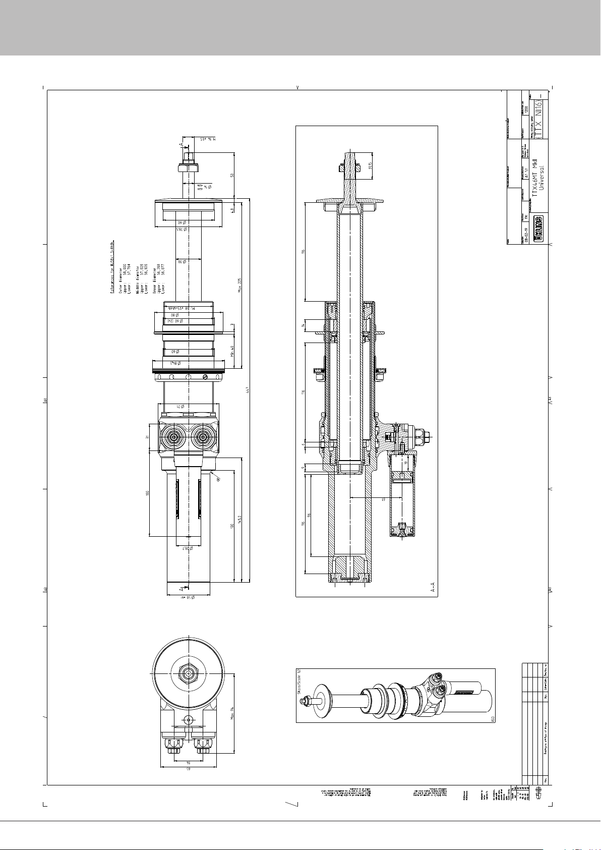
42
20 - Damper Dimensions
41
Page 43
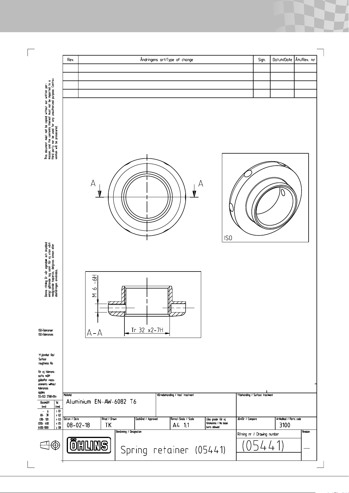
20 - Damper Dimensions
42
Page 44
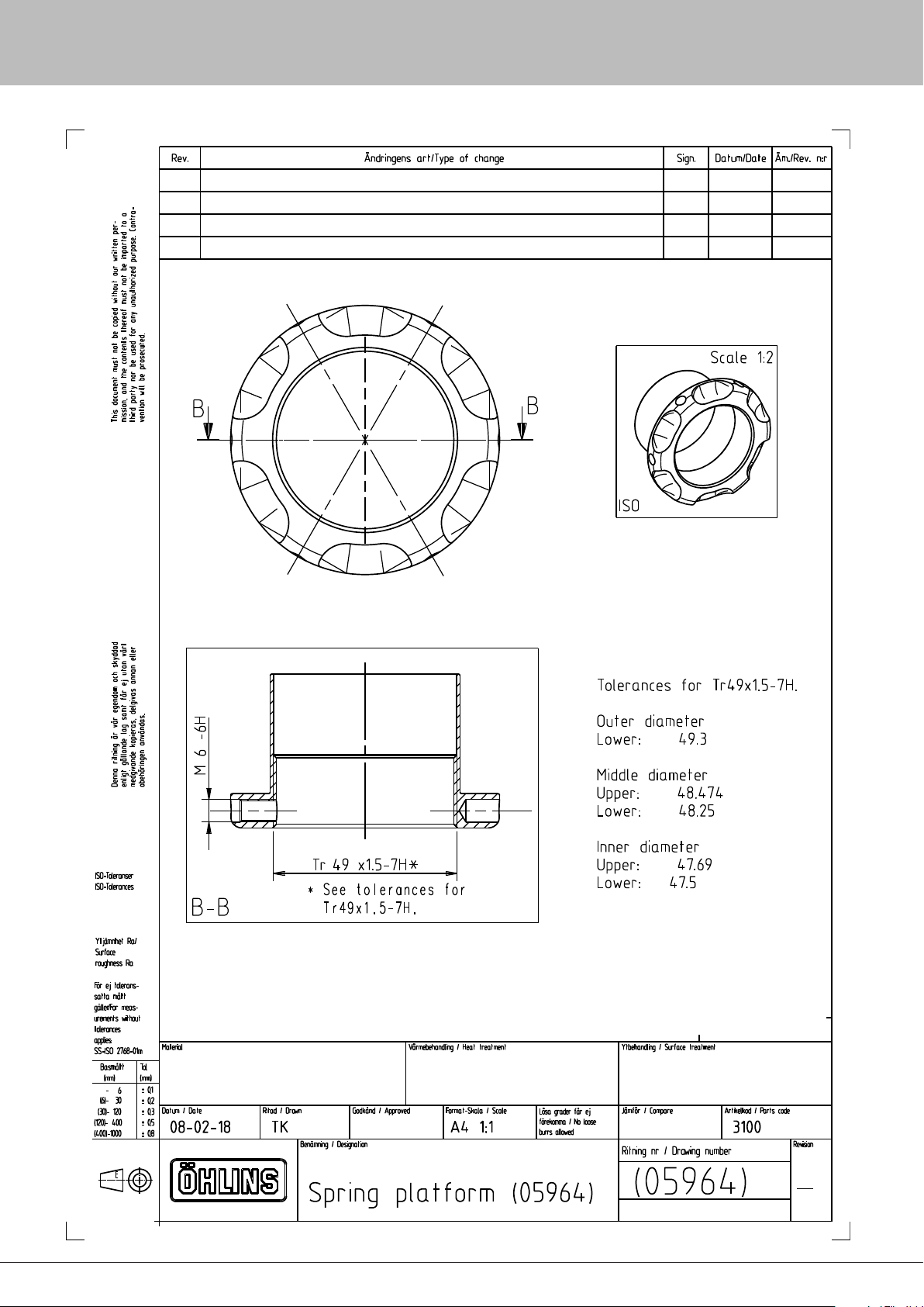
44
20 - Damper Dimensions
43
Page 45
20 - Damper Dimensions
44
Page 46
46
20 - Damper Dimensions
45
Page 47
20 - Damper Dimensions
46
Page 48
48
20 - Damper Dimensions
47
Page 49
20 - Damper Dimensions
48
Page 50
50
20 - Damper Dimensions
49
Page 51
20 - Damper Dimensions
50
Page 52
52
20 - Damper Dimensions
51
Page 53
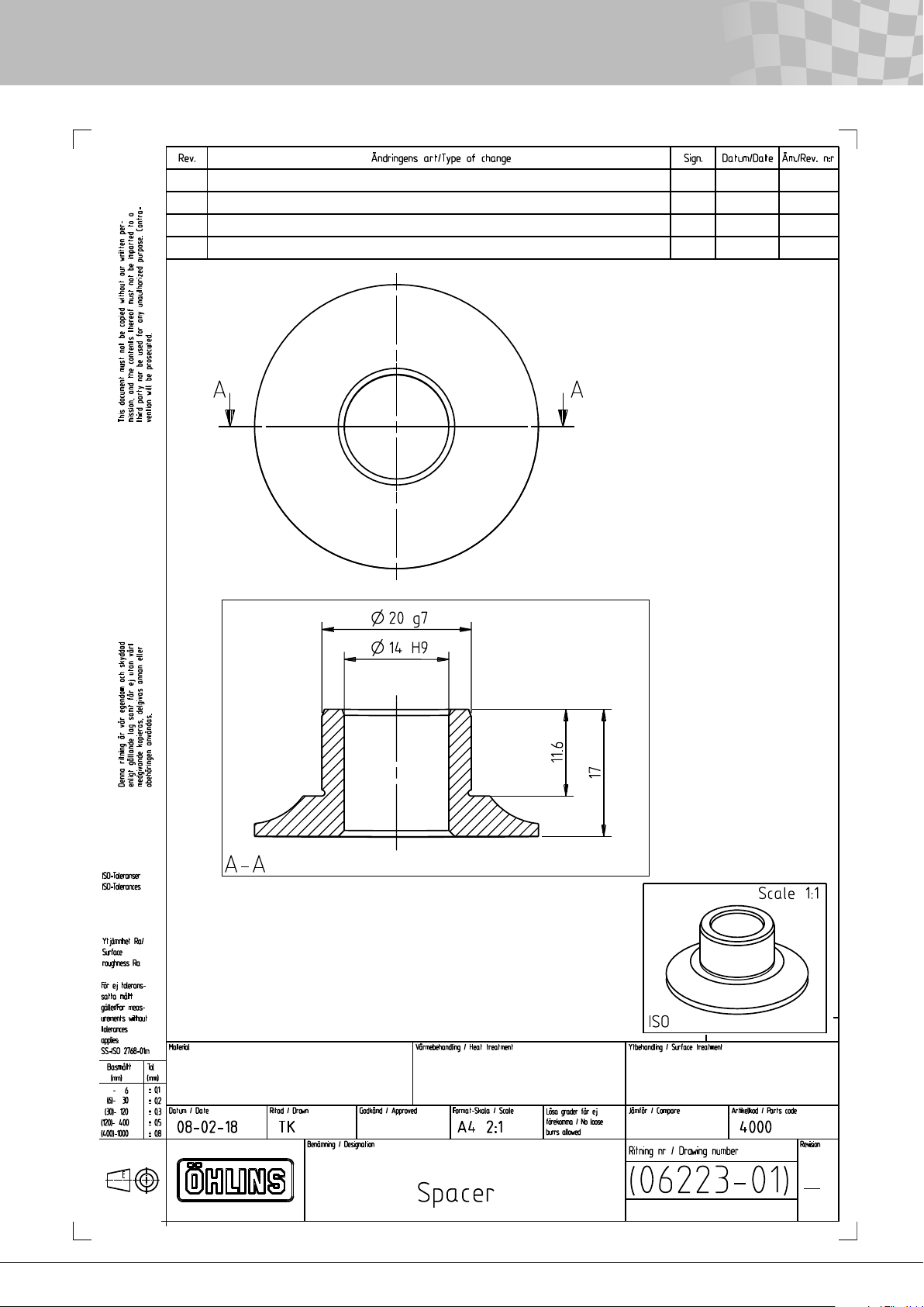
20 - Damper Dimensions
52
Page 54
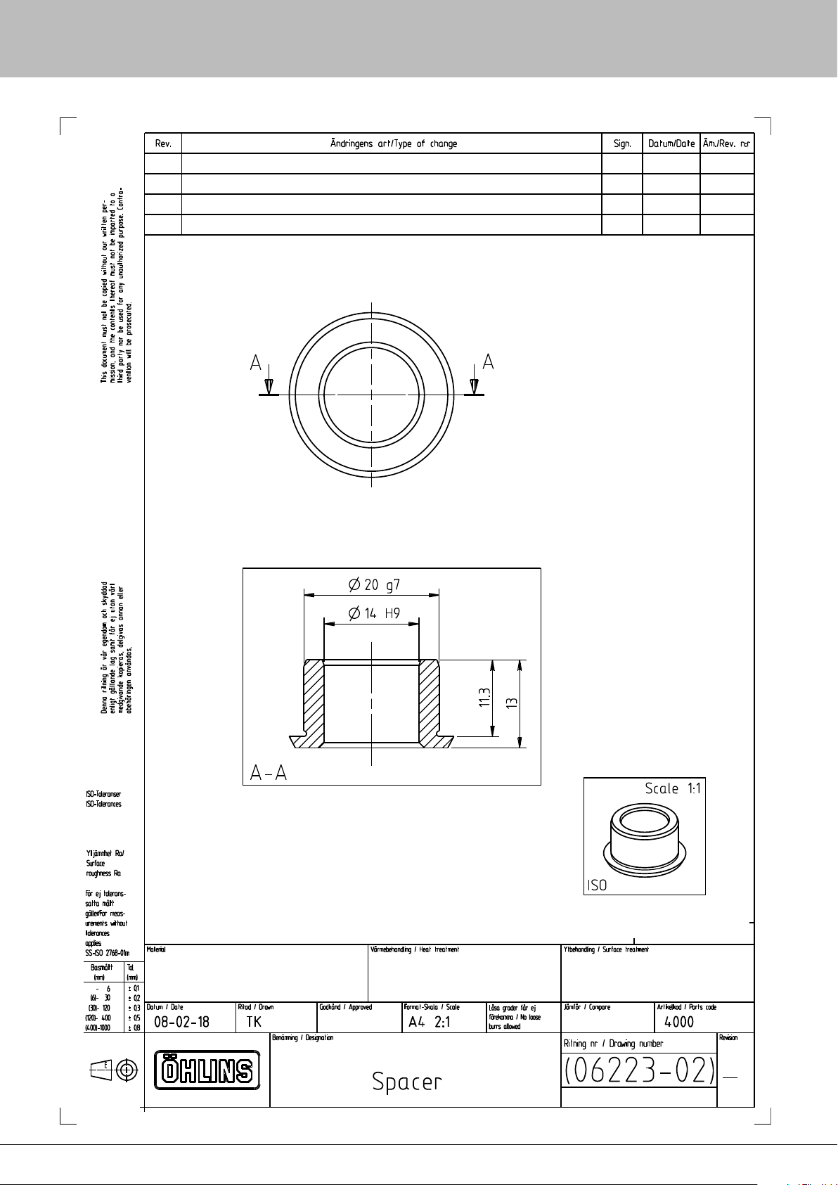
54
20 - Damper Dimensions
53
Page 55
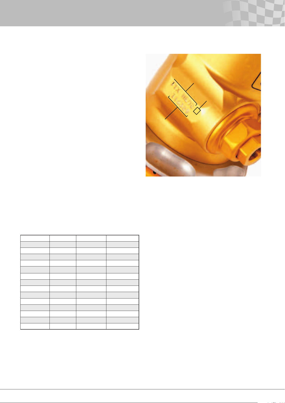
21 - Damper Identification
All Öhlins dampers are marked with the damper part number and
the production order number. On the TTX40/TTX46 MT damper,
these numbers are placed on the side of the cylinder head/valve
housing.
The marked part number has one digit added to the number. This
digit signies the revision number.
Keep in mind that as some of the customers rebuild dampers
themselves, the hardware conguration can be changed from
the time when the damper was produced. As a result these part
numbers are not a denite indication of the installed hardware on
that particular damper.
Part No.
Revision No.
Production
batch No.
22 - Technical Data
Stroke [mm] Length* [mm] Weight [g]**
TTX NE01 48 207.6 810
TTX NH01 48 207.6 780
TTX NE02 56 243.6 880
TTX NH02 56 243.6 845
TTX NE03 68 264.6 910
TTX NH03 68 264.6 855
TTX NE04 80 321.6 1025
TTX NH04 80 321.6 980
TTX NE06 110 390.6 1145
TTX NH06 100 390.6 1165
TTX NE08 140 480.6 1345
TTX NH08 130 480.6 1320
TTX NH16 116 447 2310
TTX NI16 116 447 2310
Figure 21.1
Damper identification.
External adjusters 4
Number of click positions:
Low Speed Compression 40
High Speed Compression 50
Low Speed Rebound 40
High Speed Rebound 50
Max recommended velocity 1.5 m/s (60 inch/sec.)
Max damping peak force 8000 N (1800 lbs.)
Max bump rubber force 8000 N (1800 lbs.)
Max operating temperature 120°C (approx. 250°F)
Oil Öhlins damper uid 309
Recommended gas pressure 5 bar (75 psi)
TTX40
The length is measured from the spherical bearing centre of the
top eye to where the lock nut on the piston rod sits against the end
eye. By adding the given length of the end eye in chapter Damper
dimensions you get the total length centre to centre of the bearings.
TTX46 MT
The length is measured from the bottom of the tube to the top
surface of the spring seat. See chapter Damper dimensions for
more info.
** Weight is measured without spring seats, end eyes and springs.
54
Page 56
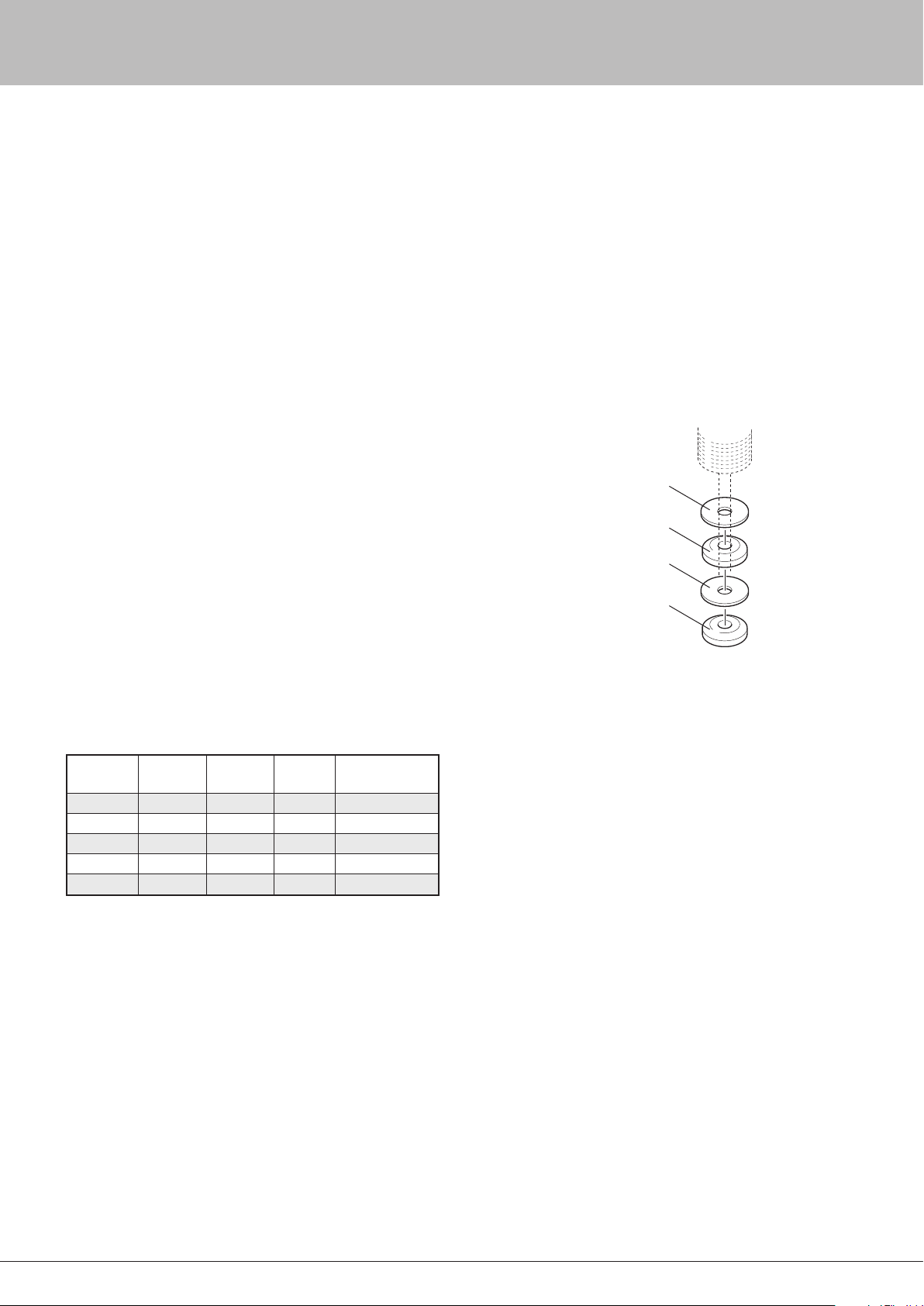
56
23 - Optional Parts
There are some optional Öhlins parts available for the TTX40 and
TTX46MT dampers. These parts are not always specically made
for the TTX40/46MT dampers and can be used together with
different Öhlins products. These parts have to be bought separately
Bump rubbers
Bump rubbers are used both as spring elements, very often
in combination with coil springs or torsion springs to achieve
increased resistance to compress the damper further into the
stroke.
The bump rubbers are normally engaged only when the damper
is compressed some distance from static ride height position. If
the bump rubber is used only when the damper is almost fully
compressed to prevent the damper from bottoming metal to metal,
the rubber is used more as a bump stop.
However, very often, the bump rubber is an active part of the
suspension. In particular, in applications with a lot of downforce.
The force produced by bump rubbers is largely position dependent,
but compared to steel coil springs, there is also quite a bit of
damping, “hysteresis”, from the bump rubbers. Increased frequency
(velocity) at given amplitude will increase the force produced both
under the loading and the unloading phase.
The hysteresis will also increase. Because of this and the nonlinearity when engaging the bump rubber, simulations including
bump rubbers are quite complicated without simplications.
Bump rubbers are just as the name indicates made out of rubber.
Öhlins mainly uses bump rubbers made out of polyurethane, a
material made with small closed cells lled with gas. Different
densities are used to produce varying spring rates.
The spring rate always increases when the rubber is compressed.
By making bump rubbers with different shapes, different
characteristics can be achieved.
Öhlins has many different bump rubbers available, these bump
rubbers are:
To increase the number of combinations some of these bump
rubbers are made short, so you can achieve different characteristics
by stacking them differently. This is done by changing the number
and type of rubber and also by playing with separately plastic
washers. Adding a separating washer between two rubbers will
increase the stiffness slightly. Below you can nd some examples of
how the force changes due to displacement.
Always use a plastic washer of type 06130-XX (12 mm shaft)
or 06233-XX (14 mm shaft) between the rubber and the cylinder
cap (part no. 06114-01 or 06251-01) to avoid damaging the bump
rubber by the holes of the cylinder cap. The thinnest washer 0613001 or 06233-01 (1 mm) is enough to handle the loads of the rubber.
Spacer (always keep
a spacer on top of the
stack)
Bump rubber
Spacer
Bump rubber
Figure 23.1 Example of a bump
rubber stack.
Part no. Shaft
diameter
05375-15 12 mm 10 mm Black 550±50 g/cm³
05375-16 12 mm 10 mm Nature 650±50 g/cm³
06375-01 14 mm 10 mm Black 550±50 g/cm³
06375-02 14 mm 20 mm Black 550±50 g/cm³
06375-03 14 mm 30 mm Black 550±50 g/cm³
Height Colour Density
55
Page 57
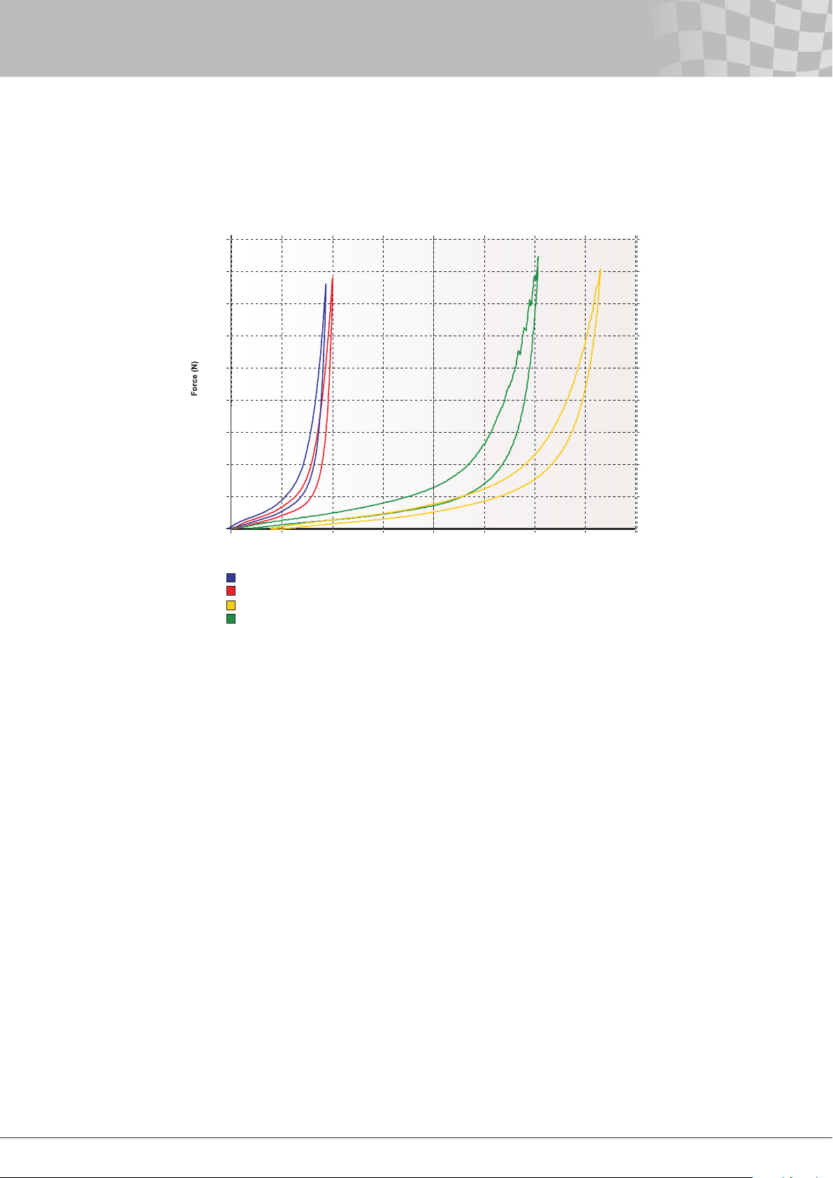
Figure 23.2
Examples of different bump rubber stiffness. The measurement took
place at low frequency.
9000
8000
7000
6000
5000
4000
3000
2000
23 - Optional Parts
1000
0
0 5 10 15 20
1 bump rubber 05375-15
1 bump rubber 05375-16
4 bump rubbers 05375-16
4 bump rubbers 05375-16 with spacer 06130-01 between the bump rubbers
The maximum load to use from bump rubbers on the TTX40
damper is 8000 N (approx. 1800 lbs). For information about the
specic bump rubbers, please contact an Öhlins distributor.
Weight jacker 05490-01
Weight jackers are used to change the balance of the car by
changing the position of one of the spring platforms. Often, the
adjustment is made directly from the cockpit. Weight jackers are
especially useful in oval racing.
For the TTX40 damper, Öhlins offers the hydraulic spring
preloader (weight jacker) 05490-01. It consists of a master cylinder
and a slave cylinder connected by a hose. By turning the adjuster
wheel of the master cylinder, the piston of the slave cylinder will
move.
The spring preloader is designed for 21⁄4 inch inner diameter (i.d.)
springs and comes with a 1500 mm long hose.
The rate is 0.5 mm/turn and the stroke is 6.5 mm.
The spring preloader can be adjusted by hand to approx. 5500 N
(1200 lbs) of load.
Maximum load to use is 11 000 N (2500 lbs).
By changing some parts in the master cylinder, the spring
preloader can be rebuilt so you get a rate of 0.75 mm per turn.
However, this will increase the torque needed for a specic load.
Displacement (mm)
25 30 35 40
If the spring preloader needs to be taken apart for whatever reason,
it is very important to get all the air out of the system when it is
assembled. If not, the stroke will be reduced and ex in the system
will increase. For the best result, use a vacuum lling machine. High
loads on the spring preloader will compress the oil and the spring
preloader, causing some ex in the system. At maximum load, the
stroke of the slave cylinder can be expected to drop about 1 mm to
5.5 mm. For further information regarding Öhlins hydraulic spring
preloader, please contact your Öhlins distributor.
There are some more Optional Parts available from Öhlins
Racing, please see the Spare Parts Manual for your specic
dampers for more information.
56
Page 58
Your Öhlins retailer:
Öhlins Owner’s Manual 07430-02_1 | Issued 2010-03-23 | © 2010 Öhlins Racing AB
Öhlins Racing AB
Box 722
SE-194 27, Upplands Väsby
Sweden
Phone: +46 (0)8 590 025 00
Fax: +46 (0)8 590 025 80
www.ohlins.com
 Loading...