

Page 1

1
Owners Manual
Öhlins 48 mm front fork TM
MX/Enduro and Supermotard
Including:
Setting up
your bike
Fine-tuning
Service
the fork
General
handling set-up
Technical info
Spare parts
Page 2
2
Safety signals
Important information concerning safety is
distinguished in this manual by the
following notations:
The Safety alert symbol means:
Caution! Your safety is involved.
WARNING!
Failure to follow warning instructions
could result in severe or fatal injury
to anyone working with, inspecting or
using the suspension, or to bystanders.
CAUTION!
Caution indicates that special precautions must be taken to avoid damage to the suspension.
NOTE!
This indicates information that is of
importance with regard to procedures.
Introduction
All of Öhlins advanced suspension products are
adapted to the brand and model. This means that
length, travel, spring, action and damping characteristics, are tested individually just for your
motorcycle.
Before installation
Öhlins Racing AB can not be held responsible for
any damage whatsoever to front fork or vehicle,
or injury to persons, if the instructions for fitting
and maintenance are not followed exactly.
Similarly, the warranty will become null and void
if the instructions are not adhered to.
© Öhlins Racing AB.
All rights reserved.
Any reprinting or unauthorized use
without the written permission of
Öhlins Racing AB is prohibited.
Printed in Sweden.
NOTE
Öhlins products are subject to continual improvement and development. Consequently, although
these instructions include the most up-to-date
information available at the time of printing, there
may be minor differences between your suspension and this manual. Please consult your Öhlins
dealer if you have any questions with regard to
the contents of the manual.
Contents
Safety signals ................................................ 2
Introduction ................................................... 2
Before installation .......................................... 2
Tuning the suspension ................................... 3
Design ........................................................... 3
Settings ......................................................... 4
Setting the spring preload ............................. 4
Fine tuning the bike ....................................... 5
Preload adjustment ....................................... 7
Changing springs .......................................... 9
Technical information ................................... 10
Spare parts .................................................. 11
General handling set-up .............................. 14
Maintenance ................................................ 15
Page 3
3
Tuning the suspension
Motorcycle road holding qualities
All motorcycles are designed with a suspension
geometry that includes height and fork angle. The
changing of components can affect this and it is
therefore essential that both the rear and the front
ends match each other.
Changing to Öhlins suspension gives optimum
performance only when both the front fork and
the rear suspension interact properly. It is of the
greatest importance that the front and rear loaded
heights are within the specified values.
In the Mounting Instructions, see section:
Setting the spring pre-load.
In the legs there are also “air-springs“ (the air
trapped above the oil) that work together with
the “real“ spring. You adjust the air-spring by
raising or lowering the oil level in the legs.
By using different combinations of springs and
air-springs you can alter the characteristic of the
fork. For example, a soft spring in combination
with a small air-spring (high oil level) makes the
fork progressive; see Fine-tuning the bike.
Marking
All Öhlins front forks are marked. You will find the
part number on the inside of the fork bottom.
Design
Öhlins new upside-down (USD) front fork is
designed to combine the advantages of comfortable, safe conventional forks and rigid, light USD
forks. The result is a unique combination of being
rigid, precise in corners and during hard braking
yet comfortable, forgiving during “over-landing“
and in big bumps.
Your new Öhlins USD front fork has aluminium
outer legs and 48 mm steel inner legs, with a
polished surface for lowest possible friction.
The new USD fork features the Öhlins cartridge
damping system.
The fork is fully adjustable with external adjuster
for compression and rebound damping.
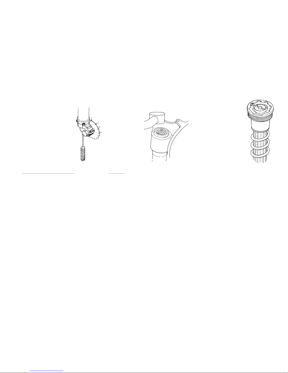
The compression adjuster is located at the bottom of the fork leg (Fig.1), the rebound adjuster
at the top (Fig.2).
Spring pre-load is adjusted with spring supports
of different heights (Fig.3), and optional springs
are available to suit different tracks and riders.
Recommended settings
The front fork in your kit is adjusted to the Öhlins
recommended setting for your bike. We advise
you to use this as your start setting.
1.
The compression adjuster is
located at the bottom of the
fork leg.
2.
The rebound adjuster
is located at the top of
the fork leg.
3.
Spring pre-load is adjusted
with different spring supports.
Optional springs are available.
Page 4
4
Settings
Basic settings
Always ensure that the basic setting made by
Öhlins is correct. It is adapted to the make and
model (in its original state) and for a rider of
average weight.
WARNING
Incorrect spring action can produce a fork angle
that is too steep or too flat.This in turn will give a
tendency for oversteering or understeering, which
could seriously affect the handling characteristics
of the motorcycle.
The original setting of the front fork, when delivered
from Öhlins, should always be a base when the
settings are changed by use of the adjustment
devices.
Recommendations
The difference should not deviate from the
following sizes, if no other recommended settings
are given in the Mounting Instructions:
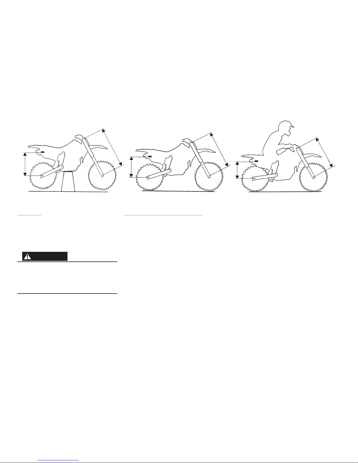
Free sag: (R1-R2), (F1-F2)
Rear: MX/Enduro/Supermotard 30±5 mm
Front: MX/Enduro/Supermotard 30±5 mm
Ride height: (R1-R3), (F1-F3)
Rear: MX 100±5 mm
Enduro/Supermotard 30% of the
total stroke
Front: MX/Enduro/Supermotard 80±5 mm
Setting the spring pre-load
Measuring
Pre-load on the spring/springs is very important,
because it affects the height of the motorcycle and
the fork angle. Consequently, handling characteristics
can be changed, even negatively. Proceed as follows
(it will be much easier if done by two persons):
• Place the motorcycle on a stand, so the
front fork and the rear end are in fully
extended position.
• Measure the distance, eg. from the
lower edge of the rear mudguard or
from a point marked by a piece of tape,
immediately above the rear wheel axle,
to the wheel axle (R1).
• Make a similar measurement on the front axle,
e.g. from the bottom of the upper fork crown
to the front wheel axle (F1).
• Allow the motorcycle (without rider) to
apply load on the springs and repeat the
measuring procedure (R2, F2).
• Then take the same measurements with
the rider and equipment on the
motorcycle (R3, F3). It is important that the rider
has a correct riding posture, so that the
weight is balanced on the front and rear
wheel in the same way as when riding.
Bike on a stand.
F1
R1
Bike on the ground.
F2
R2
Bike with rider on.
F3
R3
Page 5
5
Fine-tuning the bike
Learning how to use the adjusters will take time
but you quickly appreciate them once you know
the tricks. Even the specialists sometimes need
a specialist!
With the adjusters you optimize the suspension for your riding style and the track you are
competing on.
The same basic guidelines go for both the front
fork and the rear shock absorber.
Too much compression damping will give you a
harsh ride as your bike “jumps“ along the track.
With too much rebound damping your bike will
have difficulties with several bumps in a row. The
suspension will not extend fast enough between
bumps, your bike will ride lower and lower and
eventually the suspension will bottom!
External adjusters
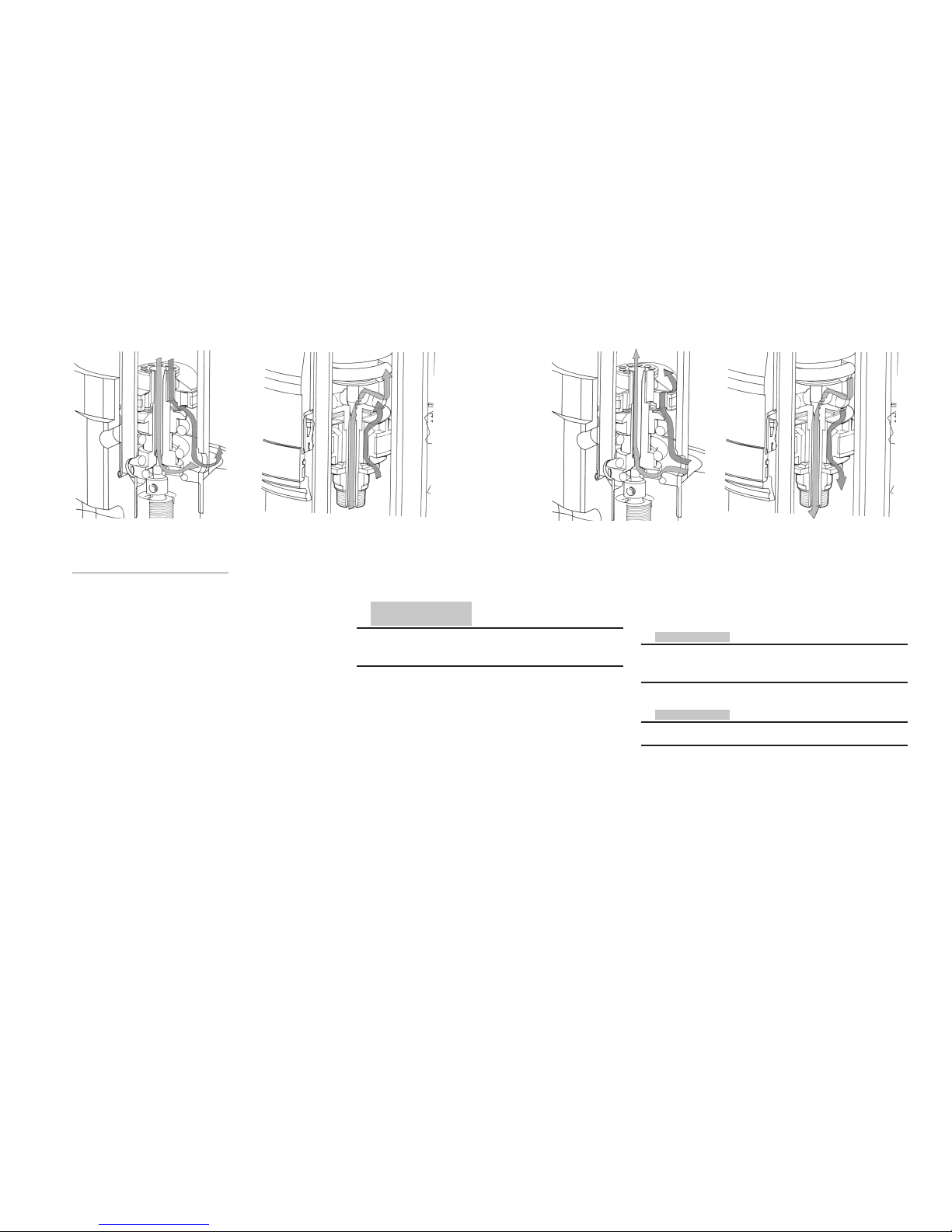
On the Öhlins front fork the adjusters are bleed
valves, completely separated from each other.
The compression bleed valve controls the flow
in the cartridge tube during the compression
stroke, the rebound bleed valve controls the flow
during the rebound stroke.
CAUTION!
Using too much force when closing the adjusters
will destroy important sealing surfaces.
learn how they effect the handling of your bike.
Make sure that you have the correct springs and
the correct spring pre-load before making any
adjustments. And always start with the Öhlins recommended settings.
Compression stroke Rebound stroke
Flow in compression valve Flow in rebound valve Flow in compression valve Flow in rebound valve
NOTE!
Higher click numbers give less damping force.
When making adjustments, keep notes, make
adjustments one at a time…and in small steps.
The adjusters should normally not be adjusted
in steps of more than 2 clicks at a time and not
outside the usable click range.
When you think you have made an improvement,
go back to what you started with and double
check to be sure. Pay attention to changes in
conditions like tires, temperatures etc.
NOTE!
See Mounting Instructions for recommended
settings.
Both the adjusters have a normal right-hand
thread.
Click position zero (0) is when the adjusters are
turned clockwise to fully closed.
The adjustment range, from fully closed until
maximum open valve (counter clockwise), is 20
clicks.
In order not to click in the wrong direction; always
first close the adjuster, then dial-in the new setting.
Making adjustments
To make improvements using the adjusters, it is
important to understand the function of the front
fork and the shock absorber and through testing
Page 6
6
In general, compression damping changes should
be used to influence the bike’s stability and response, while rebound damping changes should
be used to influence comfort and traction.
When you need more damping force, you should
mainly try to increase compression damping and
use as little rebound damping as possible.
This usually means that you gain comfort and
performance in handling.
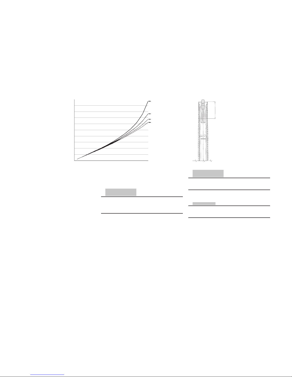
Oil level adjustment
As the air trapped between the oil and the top
nut acts as an air-spring, a change in oil level will
effect the damping forces. Not in the early stage
of fork travel, but a great deal in the later stage.
A general description of how the oil level/airspring effects the damping forces are shown in
Fig.4.
The air-spring gives the Öhlins USD fork a progressive spring rate, preventing it from bottoming
out hard.
By using different combinations of springs and oil
levels/air-springs you can alter the characteristic
of the fork and tailor it to suit different tracks and
conditions.
CAUTION!
The oil level must be the same in both front fork legs.
Riding a bike with different oil levels will cause
instability.
When the oil level is raised
The air-spring in the later half of travel is strong,
and thus the front fork hard.
When the oil level is lowered
The air-spring in the later half of travel is soft,
and thus the front fork soft.
CAUTION!
Adjust the oil level with the fork leg fully compressed and no pre-load washer or spring installed.
NOTE!
See Mounting Instructions for recommended oil
level.
The oil level is measured from the top of the outer
leg, with the top nut off (Fig.6).
Changes in oil level should be made in small
steps. We recommend a change of 5 mm at a
time and not outside the range of 80-130 mm.
Oil level
5.
Oil level is measured
from the top of the
outer leg, with the top
nut off, the fork fully
compressed and no
pre-load washer or
spring installed.
Oil level
Air spring
4.
A change in oil level
will effect the damping forces, not in the
early stage of fork
travel but a great
deal in the later
stage.
Force
Stroke
Oil level 100 mm
Oil level 110 mm
Oil level 120 mm
Oil level 130 mm
❿
❿
Page 7
7
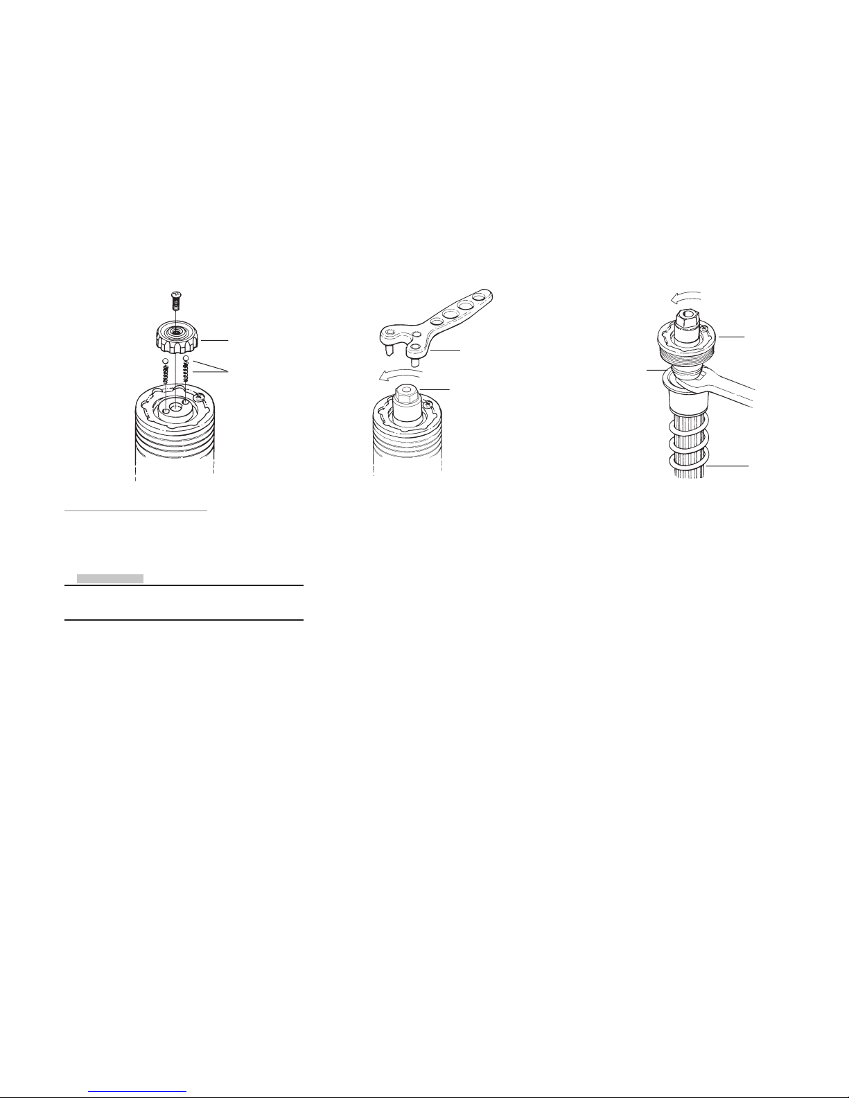
Pre-load adjustment
1
Put the bike on a stand and loosen the screws in
the top fork crown that hold the fork legs.
NOTE!
On most MX-bikes you have take of the handle
bar off before you can unscrew the top cap.
Remove the adjustment wheel and the springs
and balls of the adjuster.
2
Unscrew the top cap, use tool (1860-01 or
1761-02).
Put a box under the front wheel so that the
springs are visible.
3
Remove the top cap from the damper rod extender.
Use a 17mm wrench, and tool (1860-01 or
1761-02).
Adjustment
wheel
Balls and
springs
Tool (1860-01)
Top cap
17 mm
wrench
Damper
rod assy
Damper rod
extender
Tool (1761-02)
Page 8
8
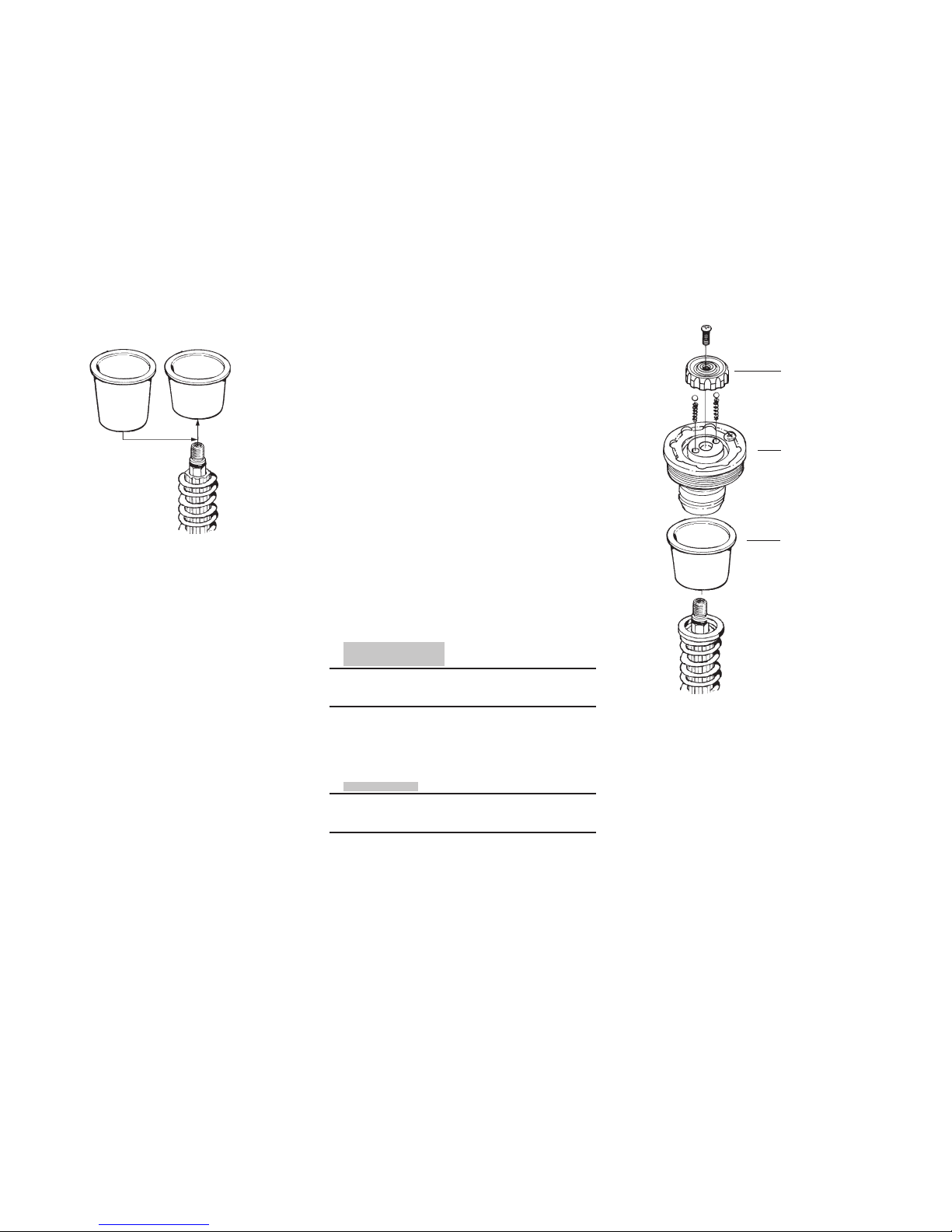
4
Remove the original spring support.
Install a new spring support to achieve the right
static sag.
5
Fit the spring support and the top cap. Tighten
the top cap and lock nut to a torque of 20 Nm.
CAUTION!
The piston shaft must bottom in the top cap
before the lock nut is tightened.
Original
spring
support
Adjustment
wheel
Top cap
Spring support
Refit the adjustment wheel.
Tighten the bolt in the top fork crown to 20 Nm.
NOTE!
The top nut only have to be tightened by hand
without extending tool.
New spring
support
Page 9
9
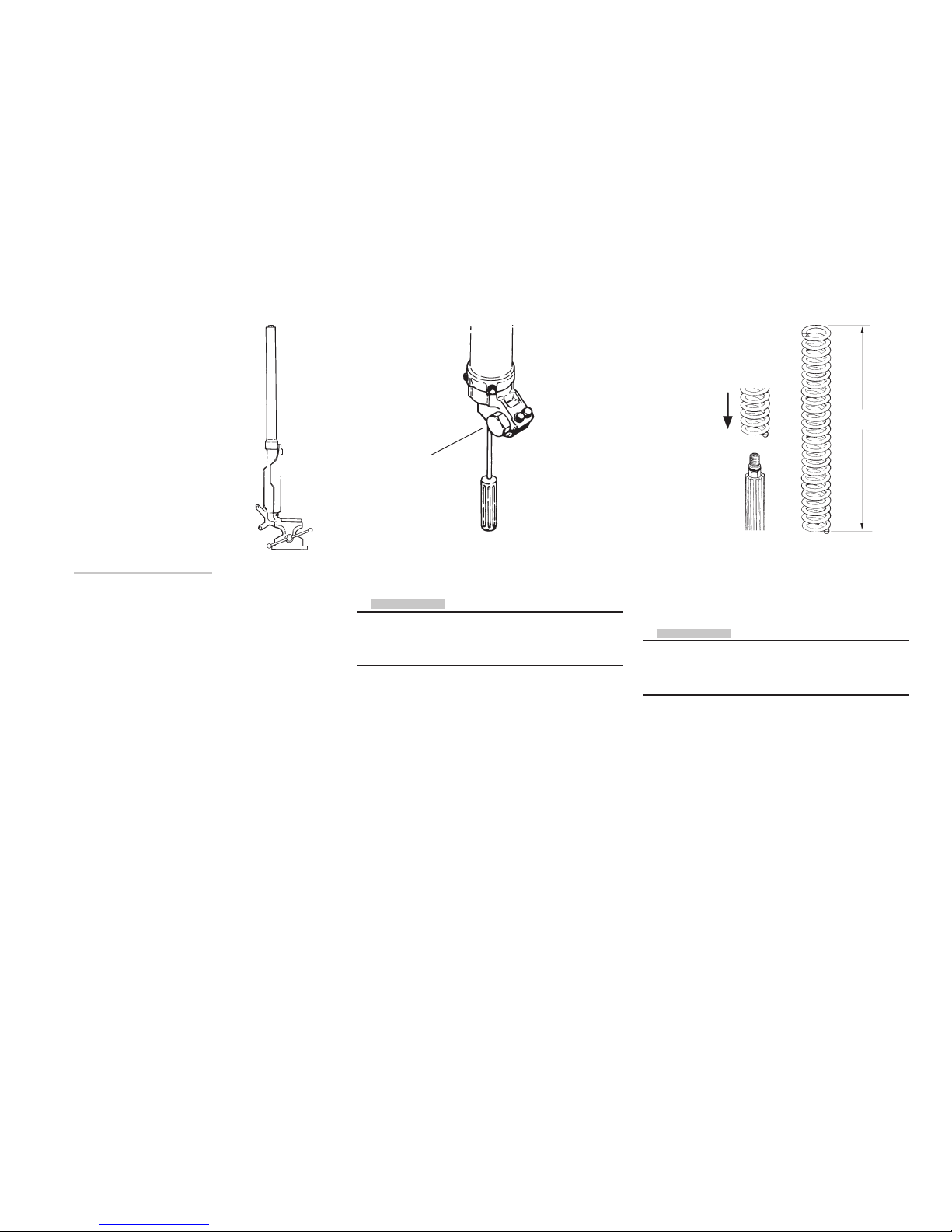
Changing springs
6
Follow instructions 1-4 on previous page and
remove the spring. Do not install the spring
support spacer.
7
8
Install the new spring.
NOTE!
Check the free length of the spring. Original length
is 467 mm. If the spring length is under 460 mm
the spring must be changed.
Follow instruction 5 on previous page.
Adjust the compression and the rebound valves
according to specification card.
Fit the fork legs to the motorcycle
Tightening torques: top fork crown 20 Nm and
bottom fork crown 10 Nm.
L ≥ 460 mm
Compression
adjuster
NOTE!
Closing the compression and the rebound valves
will keep the damper rod extended making it
easier to install the new spring.
Check the oil level according to page 6 and 10.
Pull out the damper rod as far as possible and
then close the compression and the rebound
valve (clockwise).
Page 10
10
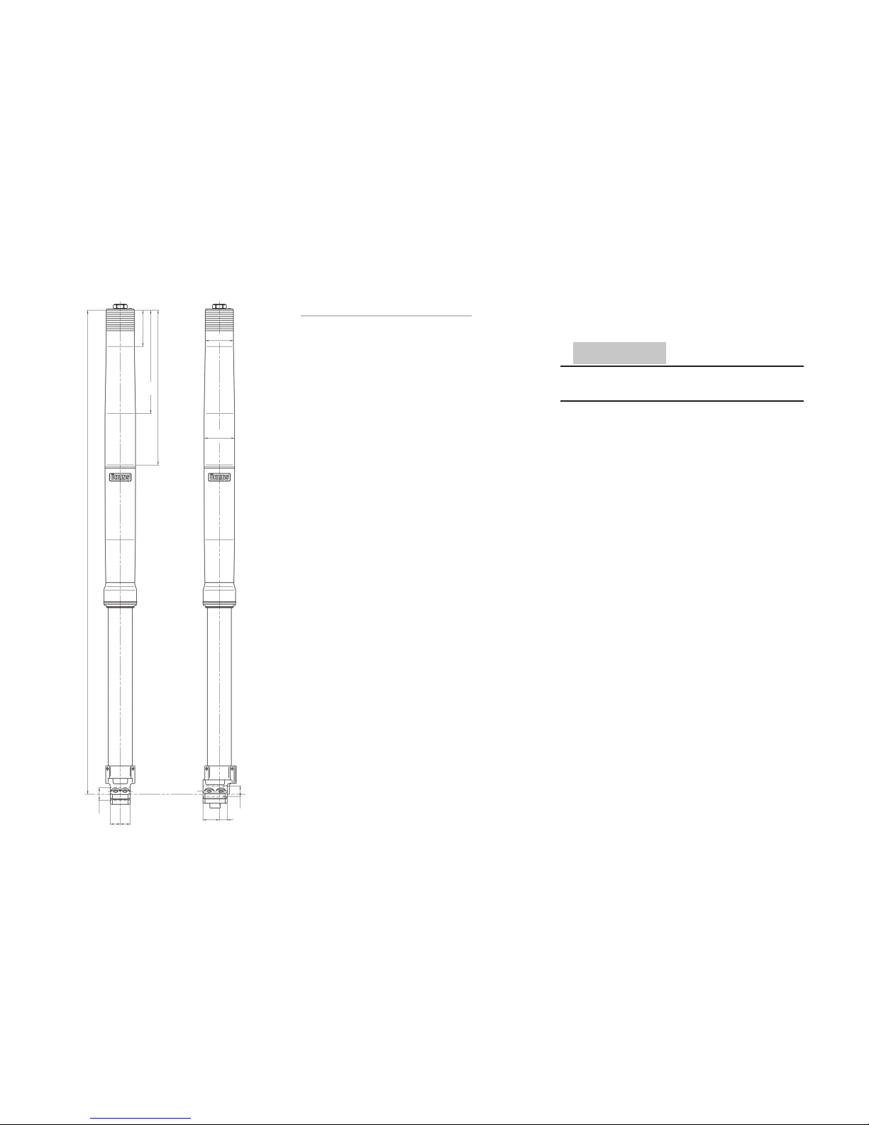
Technical specifications
Fork lengths and diameters
Front fork
ØA ØB
53.9 mm 59.3 mm
Length (L)
MX/Enduro Supermotard
935 mm 904 mm
Rebound and compression adjustment
Refer to mounting instruction for set-up data.
Maximum open rebound and compression valve:
20 clicks.
Free Spring Length:
MX/Enduro: 467 mm (service limit 460 mm).
Supermotard: 436 mm (service limit 429 mm).
Spring pre-load:
Maximum allowed adjustment
range 4-8 mm (with optional spring support).
Spring rate (depending on models):
MX/Enduro Supermotard
2428-39: 3.9 N/mm 2490-41: 4.1 N/mm
2428-41: 4.1 N/mm 2490-43: 4.3 N/mm
2428-43: 4.3 N/mm 2490-45: 4.5 N/mm
2428-45: 4.5 N/mm 2490-47: 4.7 N/mm
2428-47: 4.7 N/mm 2490-49: 4.9 N/mm
2490-51: 5.1 N/mm
Settings:
Compressing adj. 12±2 clicks
Rebound adj. 12±2 clicks
ØA
ØB
L
70
300
200
Oil level:
Adjustment range: 80-130 mm.
CAUTION!
Use only Öhlins high performance front fork fluid
No. 5 (1305-01).
Tighten torque:
Fork top crown bolt: 20 Nm
Fork bottom crown bolt: 10 Nm
Compression valve: 65 Nm (Base valve).
Cylinder tube cap (cartridgetube): 65 Nm
Compression valve, 8 mm nut 8 Nm.
Rebound valve, 8 mm nut 8 Nm.
Grease:
Öhlins Front Fork grease 00146-01
(Red grease).
Service Intervals:
Every 20 hours.
Page 11
11
5
6
7
8
9
11
12
13
14
15
16
18
19
1
2
3
4
17
21
22
23
20
22
10
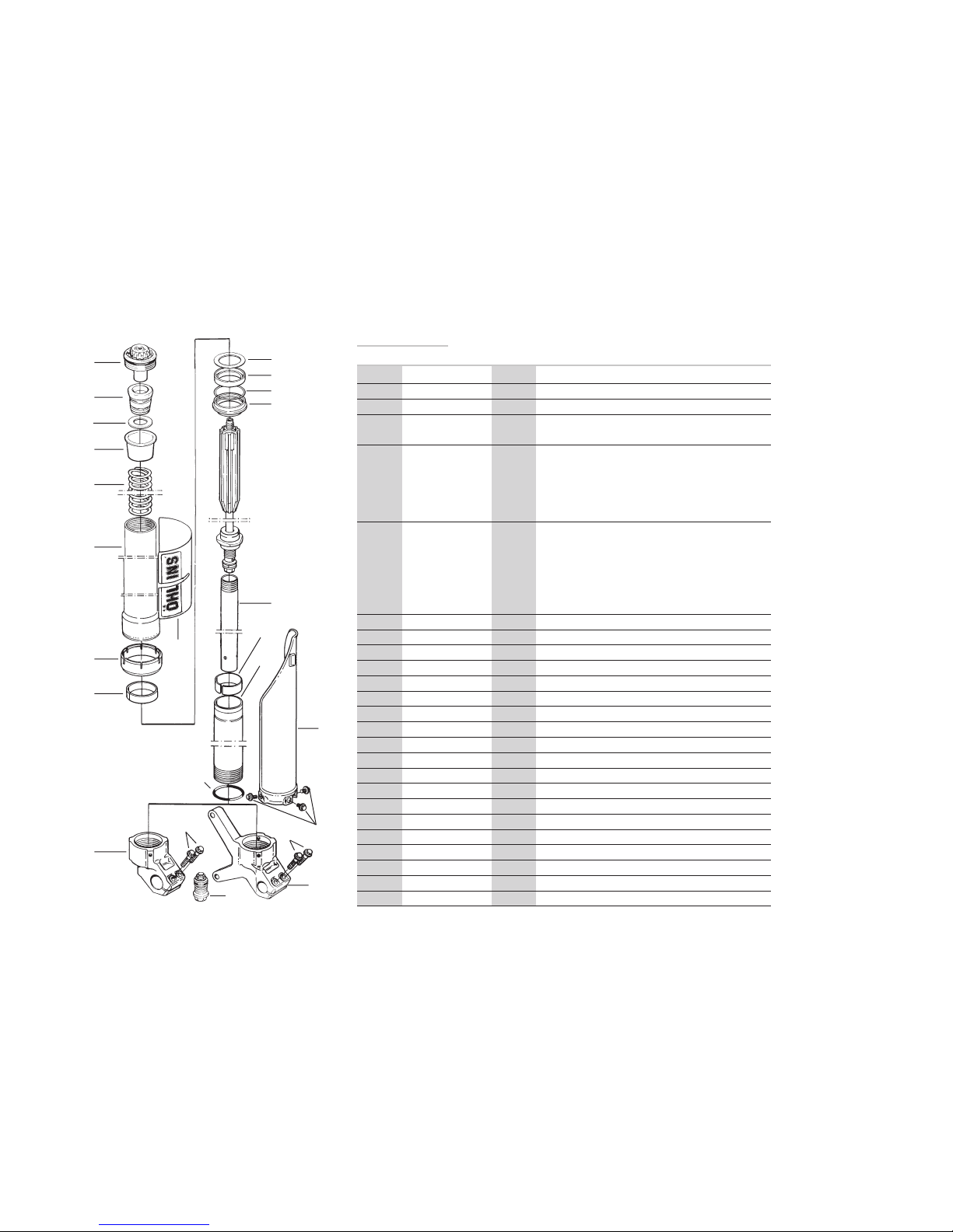
Spare parts
Pos. Part No. Pcs. Description Type/remarks
1 - 1 Top Cap
2 02400-01 1 Bump rubber
3 02403-01 1 Slide washer
4 02436-04 1 Spring support 4 mm pre-load
02436-08 1 Spring support 8 mm pre-load
5 02428-39 1 Spring front fork 3,9 N/mm
02428-41 1 MX/Enduro 4,1 N/mm
02428-43 1 4,3 N/mm
02428-45 1 4,5 N/mm
02428-47 1 4,7 N/mm
5 02490-41 1 Spring front fork 4,1 N/mm
02490-43 1 Supermotard 4,3 N/mm
02490-45 1 4,5 N/mm
02490-47 1 4,7 N/mm
02490-49 1 4,9 N/mm
02490-51 1 5,1 N/mm
6 02425-41 1 Fork leg outer
7 02332-07 1 Cover Sticker Öhlins
8 02409-01 1 Guide Sleeve
9 02427-02 1 Bushing lower
10 02412-01 1 Washer
11 02410-02 1 Seal
12 02015-01 1 Circlip
13 02411-02 1 Scraper
14 02339-01 1 Cylinder tube cartridge
15 02429-02 1 Bushing upper
16 02426-01 1 Fork leg inner
17 00438-16 1 O-ring
18 02309-80 1 Cover fork leg pair
19 02314-01 3 Bolt
20 02396-29 1 Fork bottom left
21 02396-30 1 Fork bottom right
22 02314-02 2 Bolt fork bottom
23 - 1 Base valve assy see page 13
- 00195-01 2 Sticker Öhlins white / transparent
Page 12
12
1
4
5
7
2
3
9
8
6
10
11
12
13
14
15
16
17
18
20
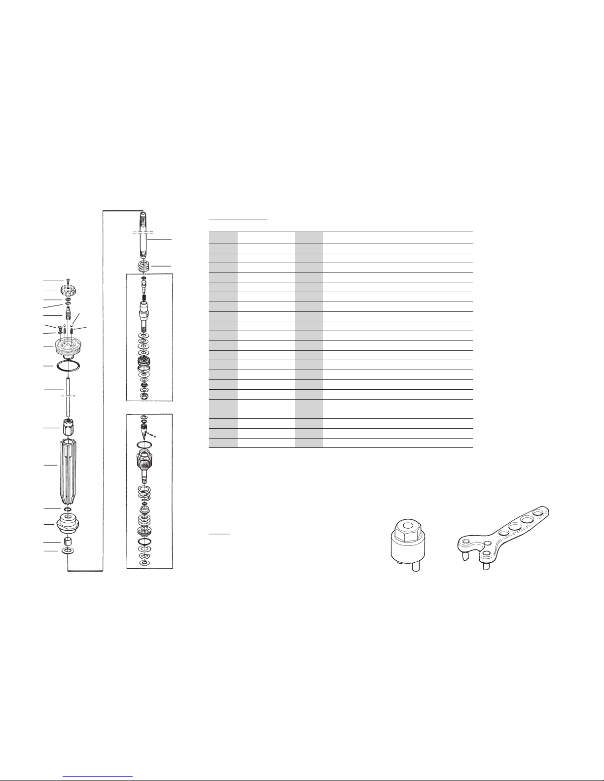
Spare parts
Pos. Part No. Pcs. Description Type/remarks
1 00828-01 1 Screw
2 00820-02 1 Adjustment knob
3 01473-06 1 Circlip
4 00338-79 1 O-ring
5 02405-01 1 Adjustment screw
6 00884-01 2 Ball
7 0883-01 2 Spring
8 01050-01 1 Screw
9 00338-59 1 O-ring
10 02397-48 1 Top cap
11 00438-61 1 O-ring
12 02366-13 1 Adjustment rod
13 02402-01 1 Lock nut
14 02430-01 1 Spring guide
15 01499-02 1 Circlip
16 02399-48 1 Cylinder tube cap
17 00110-03 1 Bushing
18 02340-01 1 Washer MX/Enduro
02340-05 1 Washer Supermotard
19 02393-01 1 Shaft
20 02063-02 1 Spring
19
Tool
1860-01: Top cap releasing tool
1761-02: Top cap releasing tool
1860-01 1761-02
Page 13
13
21
22
23
24
25
26
27
28
29
30
31
32
34
33
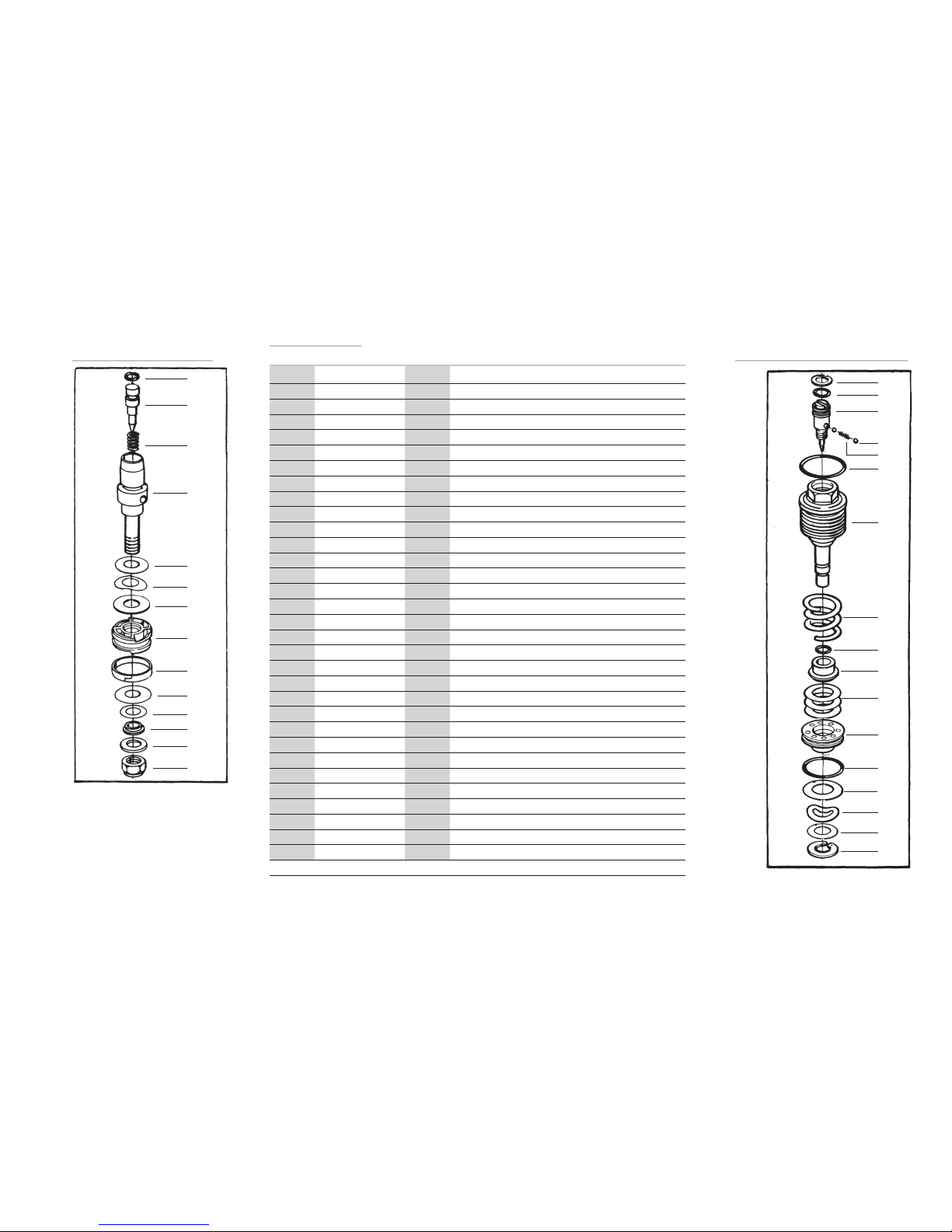
Compression adjusterRebound adjuster
44
36
37
38
39
40
41
42
43
35
45
46
47
50
48
49
Spare parts
Pos. Part No. Pcs. Description Type/remarks
21 00438-31 1 O-ring
22 02356-03 1 Rebound needle
23 02322-01 1 Spring
24 02320-03 1 Piston holder
25 00530-18 1 Shim see spec. card
26 01149-01 1 Wave washer see spec. card
27 - - Shims see spec. card
28 02335-01 1 Rebound piston
29 01447-02 1 Piston ring
30 - - Shim see spec. card
31 - - Shim see spec. card
32 00641-xx 1 Clamp washer see spec. card
33 00153-01 1 Washer
34 00430-05 1 Lock nut
35 01473-02 1 Circlip
36 00338-53 1 O-ring
37 01242-0x 1 Adjustment needle see spec. card
38 00884-04 2 Ball
39 01248-01 1 Spring
40 00438-02 1 O-ring
41 02413-xx 1 Base valve see spec. card
42 04107-x0 1 Spring see spec. card
43 00438-52 1 O-ring
44 02414-01 1 Poppet valve
45 - - Shim
46 02415-01 1 Valve seat
47 00438-03 1 O-ring
48 00520-23 1 Shim
49 04105-01 1 Wave washer
50 00530-18 x Shim see spec. card
51 05009-12 1 Circlip
51
Page 14

14
General handling set-up
Front suspension.
Front fork travel is not used to its full
capacity. Harsh feeling, front wheel grip is
not satisfactory in bumpy turns.
Suspension too hard.
• Decrease the front fork
compression damping.
• Change to softer springs.
Suspension bottoming, too soft during
entire travel.
Spring too weak or compression damping too soft.
• Increase oil level 5 mm.
• Increase compression damping.
• Change to stiffer springs.
Suspension bottoming, but can handle
smaller bumps.
Damping force not progressive enough.
• Increase the oil level.
Can handle smaller bumps but is too hard
during the last part of the travel.
Damping force is too progressive.
• Decrease the oil level.
Front end feels low, initially feels soft, but is
not bottoming.
The initial spring rate is too soft or spring preload
is too low.
• Increase the spring pre-load.
Feels harsh over small bumps, but using full
wheel travel.
Too much spring pre-load or too much compression damping.
• Increase the oil level or change
to softer springs.
• Decrease the compression damping.
• Decrease the spring pre-load.
• Clean the oil seals and scrapers. Use Öhlins
grease 146-01 for regreasing.
Can handle the first in a series of bumps but
feels hard after a few more bumps. Frontal
grip insufficient in rough and bumpy turns.
Too much rebound damping.
• Decrease the rebound damping.
Front end rebound too fast after a bump.
Front wheel grip insufficient in bumpy
curves.
Not enough rebound damping, or too much
spring pre-load
• Increase the rebound damping.
• Decrease the spring pre-load.
Front end ”ploughs”, understeers.
Shallow front fork angle. Front end too high in
comparison to rear end.
• Decrease the front fork
compression damping.
• Raise the fork legs approximately
5 mm in the triple clamp.
• Change to softer fork springs.
Front end unstable at high speed, unstable
when accelerating out of curves.
Front fork angle too steep. Front end too low in
comparison to rear end.
• Lower the fork legs approximately
5 mm in triple clamp.
• Change the front fork springs to
harder ones.
Front end unstable during deceleration.
Front fork angle too steep during braking. Front
end too low or rear end too high.
• Increase the oil level in the front fork.
• Change to harder fork springs.
• Increase the front fork
compression damping.
Front end falls into the curves (oversteering)
especially in sand.
Steep front fork angle. Front end too low in comparison to rear end.
• Increase the front fork
compression damping.
• Change to harder springs.
• Lower fork leg approximately
5 mm in the triple clamp.
Page 15

15
Maintenance
Telescopic front forks depend on a smooth, friction
free action.
Make sure your forks are regularly serviced.
Do not use strong solvents, such as brake
cleaner, to clean the front forks. This will dry out
the seals and the steel tubes and cause friction
or leakage.
After every race
Clean externally and spray with an all-purpose
oil after washing with detergent.
Check externally for damage.
Put a little Öhlins red grease (146-01) on the steel
tubes and work it in by pushing the fork up
and down.
Every 20 hours
Dismantle the fork and check all parts for wear
and damage, replace if necessary.
NOTE!
Discarded Öhlins products should be handled
over to an authorized work shop or distributor for
proper disposal.
Page 16

16
07295-16, Issued 03 09 23. Teknisk Illustration. 1500 ex.
Öhlins Racing AB, Box 722, S-194 27 Upplands Väsby, Sweden
Phone +46 8 590 025 00, Fax +46 8 590 025 80
Your Öhlins dealer:
More info
www.ohlins.com
 Loading...