

Page 1
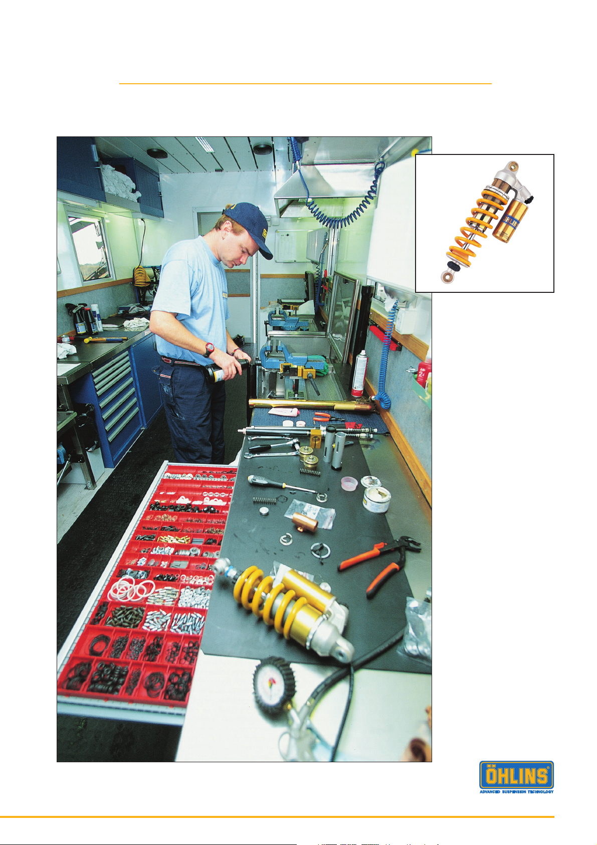
Work Shop Manual
General Manual for Öhlins shock absorbers
© Öhlins Racing AB. All rights reserved. Any reprinting or unauthorized use without the
written permission of Öhlins Racing AB is prohibited. Printed in Sweden.
1
Page 2
Introduction
All of Öhlins advanced suspension products are adapted
to the make and model. This means that length, travel,
and spring-action and damping characteristics, are tested
individually just for the vehicle fitted with Öhlins suspension. When servicing be sure to use the correct spare
parts.
The information, illustrations and specifications contained
in this manual are the latest product information available
at the time of publication. This manual is presented to make
the service of the Öhlins shock absorbers as easy and as
safe as possible with maximum performance out of the
serviced shock absorber as possible.
Safety signals
Important information concerning safety is distinguished in this manual by the following notations:
The Safety alert symbol means:
Caution! Your safety is involved.
WARNING!
Failure to follow warning instructions could result in
severe or fatal injury to anyone working with,
inspecting or using the suspension, or to bystanders.
CAUTION!
Caution indicates that special precautions must be
taken to avoid damage to the suspension.
NOTE!
This indicates information that is of importance with
regard to procedures.
Before you start
Öhlins Racing AB can not be held responsible for any
damage whatsoever to spare parts, suspension or vehicle,
or injury to persons, if the instructions for fitting and
maintenance are not followed exactly. Similarly, the
warranty will become null and void if the instructions are
not adhered to.
Make sure you have all the necessary tools before you
start working on the Öhlins shock absorber.
WARNING!
Please study and make certain that you fully understand the
work shop manual before handling the shock absorber. If
you have any questions regarding proper service procedures,
contact an Öhlins dealer or other qualified person.
NOTE!
Öhlins products are subject to continual improvement and
development. Consequently, although these instructions
include the most up-to-date information available at the
time of printing, there may be minor differences between
your suspension and this manual. Please consult your
Öhlins dealer if you have any questions with regard to the
contents of the manual.
WARNING!
The shock absorber is provided with a separate type reservoir filled with high-pressure nitrogen gas. To prevent
danger of explosion, study and make certain that you fully
understand the following information before handling the
shock absorber.
The manufacturer cannot be held responsible for damage to property or personal injury that may result from
improper handling.
1. Never tamper with or attempt to disassemble the cylinder or the reservoir.
Contents
Introduction ................................................................ 2
Safety instructions ...................................................... 2
McPherson 36 and 46 ............................................... 3
Shock absorber 46 .................................................. 15
Shock absorber 36 .................................................. 27
General .................................................................... 43
Drawings ................................................................. 55
2. Never expose the shock absorber to an open flame or
other excessive heat. The shock absorber may otherwise
explode due to too high pressure.
3. Be careful not to damage any part of the gas reservoir.
A damaged gas reservoir will impair the damping performance or cause malfunction.
4. Take care not to scratch the contact surface of the piston rod of the cylinder; oil could otherwise leak out.
5. Never attempt to remove the plug at the bottom of the
nitrogen gas reservoir. Any attempt to remove the plug
implies serious danger.
6. When scrapping the shock absorber follow the instructions for disposal.
2
Page 3

McPherson
36 and 46
Contents
McPherson 36 and 46 ............................................... 3
Dismantling the shock absorber .................................. 4
Dismantling the piston shaft ........................................ 6
Reassembling the piston shaft .................................... 7
Changings of bushing ................................................. 9
Assembling of McPherson shock absorber ............... 11
Shock absorber 46 .................................................. 15
Shock absorber 36 .................................................. 27
General .................................................................... 43
Drawings ................................................................. 55
3
Page 4
1:1
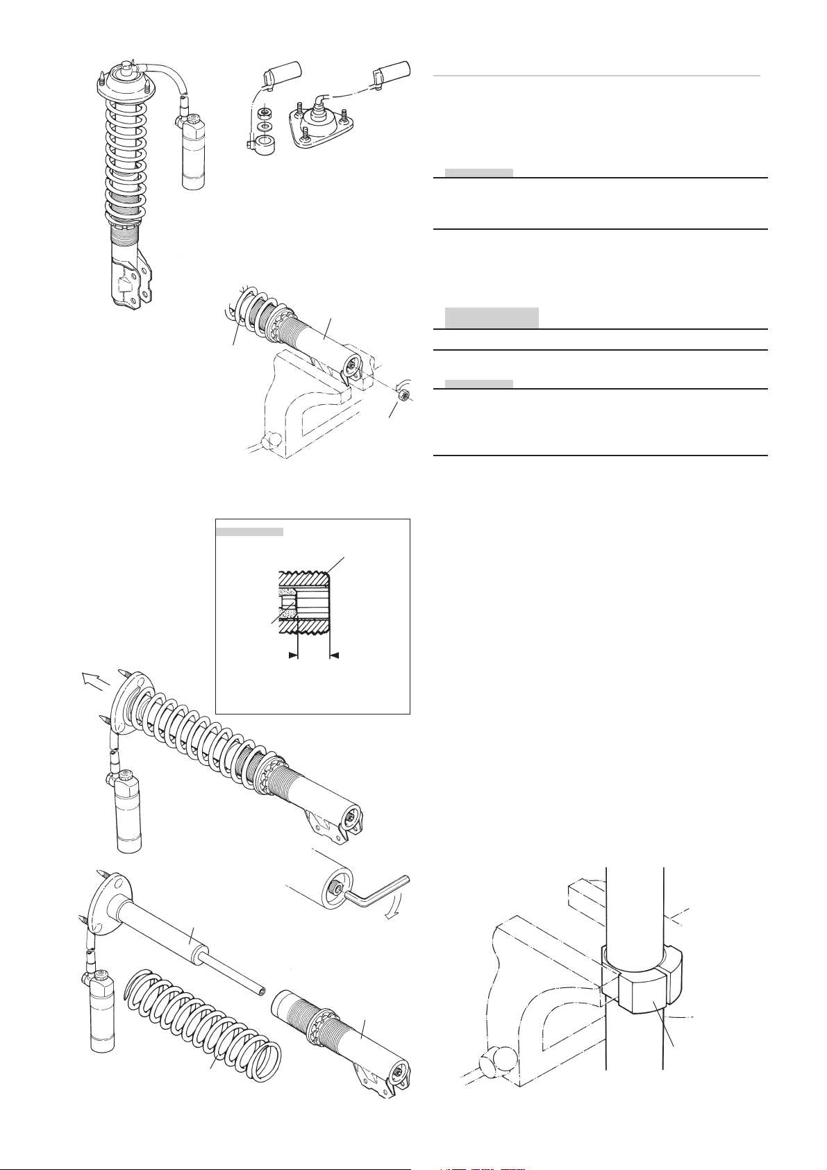
Dismantling the McPherson suspension
1:1
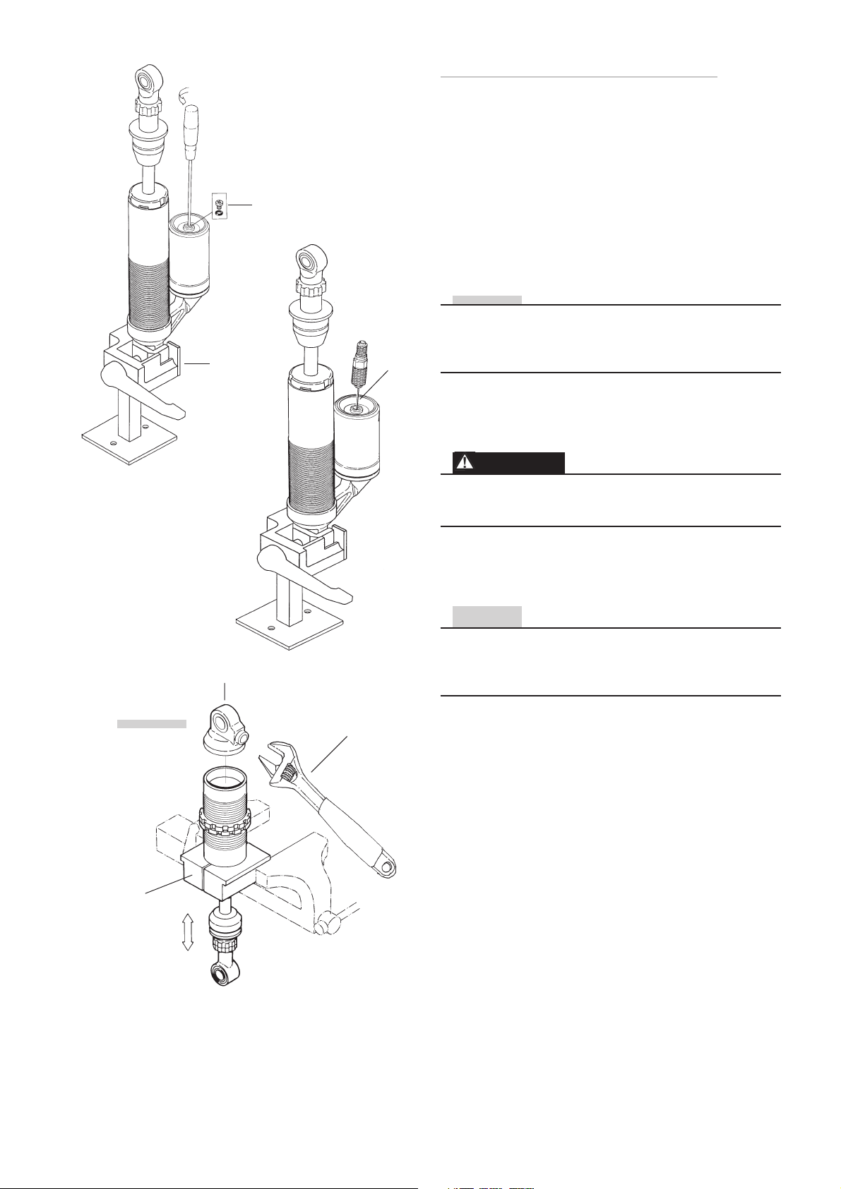
Remove the shock absorber from the vehicle by loosening first the top mount and then the lower bracket. Remove the strut from the vehicle.
NOTE!
To remove and service the shock absorber in McPherson
struts it is not necessary to remove the spring seats on
the strut, the top mount or the hose connected reservoir.
1:2
Fasten the strut in a vice. Loosen the lock nut at the lower
end of the strut.
Insert
NOTE!
Rebound
adjuster
1:2
Maximum
allen key
grip
Strut
Piston
shaft
Nut
CAUTION!
On struts without wheel bracket, use soft jaws.
NOTE!
To obtain maximal grip for the allen key, it is advisable to
close the rebound adjuster before the insert is removed.
Close by turning the adjuster wheel/screw clockwise.
Count the steps (clicks) when the wheel is turned.
1:3
Insert an allen key into the piston shaft and thread the
shaft out from the strut bottom. Free the insert by pulling
it out from the strut.
1:4
Remove the spring, clean the shock absorber and strut
carefully externally and inspect for damages.
1:5
Fasten the insert in a vice by use of soft jaws 1808-01
(50 mm) or 1808-02 (54 mm).
1:4
1:3
1:5
Insert
Strut
Tool
1808-01, 02
Spring
4
Page 5
1:6 1:7
Injection
needle
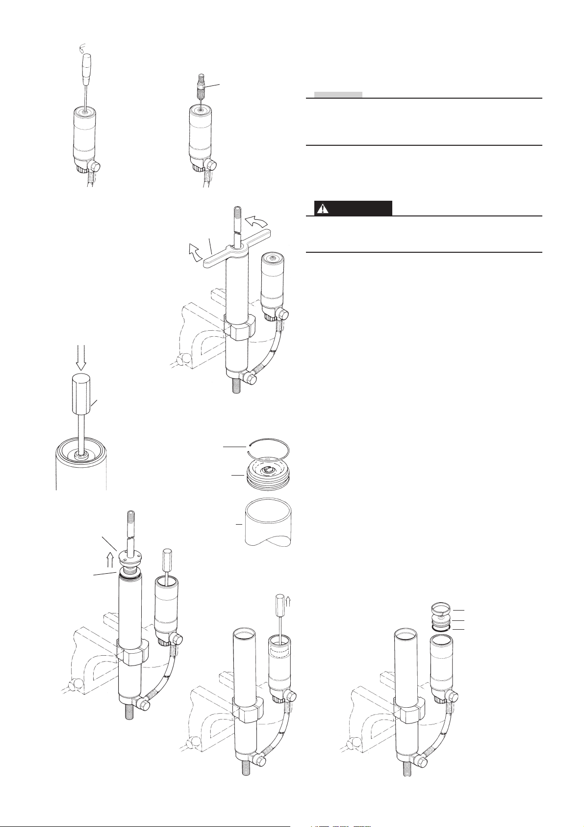
1:6
Remove the screw and o-ring from the reservoir end cap
(Shock absorber head on shock absorber models without
external reservoir.)
NOTE!
Before the gas pressure is relieved the adjuster settings
must be counted and noted. Even check that the gas
pressure is correct. Following that, the adjusters should
be set in a fully open position.
1:7
Relieve the nitrogen gas pressure by inserting an injection
needle into the shaft through the rubber valve.
1:9
Tool
720-03
Tool
1858-01
Circlip
End cap
1:8
1:10
WARNING
Releasing high pressure gas from the shock absorber can
be hazardous. Do not perform any kind of service until
gas pressure is completely released.
1:8
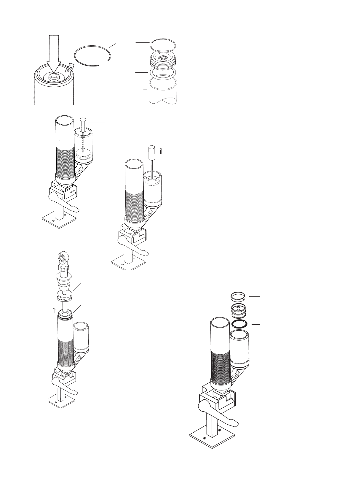
Use tool 1858-01 to loosen and remove the cylinder end
cap. Push the seal head down and remove the circlip.
1:9
Push the end cap of the reservoir down into the reservoir,
use tool 720-03.
1:10
Remove the circlip. Remove the end cap.
1:11
Pull the shaft assembly up carefully and remove it from
the cylinder tube.
1:12
Drain the shock absorber from oil.
1:13
Remove the dividing piston with tool 720-02 and drain
the oil again.
End cap
Seal head
assembly
1:11
Reservoir
1:13
1:14
Remove all o-rings and seals.
1:15
Clean all parts carefully.
1:14
Teflon band
Dividing piston
O-ring
5
Page 6
O-ring
2:2
Piston band
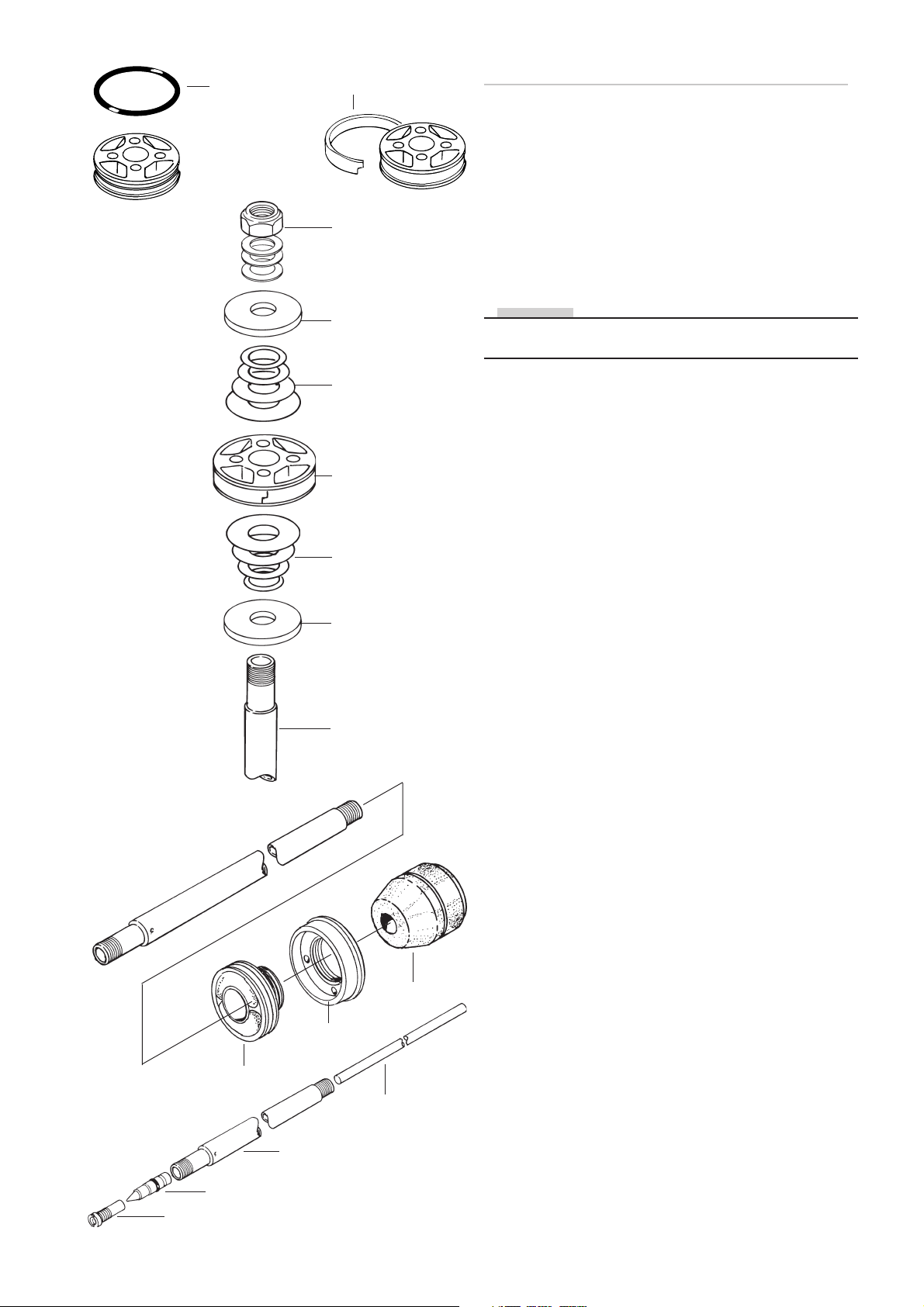
Dismantling the piston shaft assembly
2:1
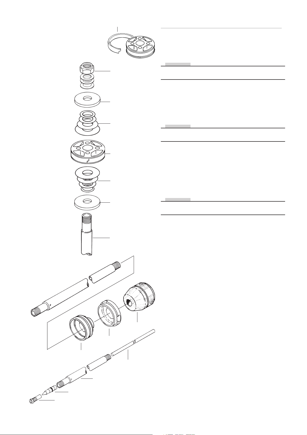
Fasten the shaft assembly in a vice with soft jaws. Use
clamping tool (727-xx)
2:3
Lock nut
Washer
Rebound
shims stack
Piston
Compression
shims stack
Washer
2:2
Remove teflon band from the damper piston
2:3
Remove the lock nut, the rebound shims stack, the
damper piston and the compression shim stack.
NOTE!
Put the shim stack aside and place the shims in the same
order as they were fitted on shaft.
2:4
Remove all the other parts from the shaft and put them
aside in correct order.
2:5
Remove the adjustment valve jet, the adjustment needle
and the adjustment pin.
2:6
Clean all parts carefully and inspect for wear or damage.
Check the o-ring of the needle and replace if necessary.
2:7
Inspect the shaft for bends and scratches.
2:8
Replace teflon ring, o-rings and lock nut.
2:4
Seal head
End cap
Piston shaft
Bump rubber
Adjustment pin
2:9
If necessary replace bump rubber, scraper ring and cap,
seal head assembly and eventual other defect parts.
2:5
Piston shaft
Needle
Valve jet
6
Page 7
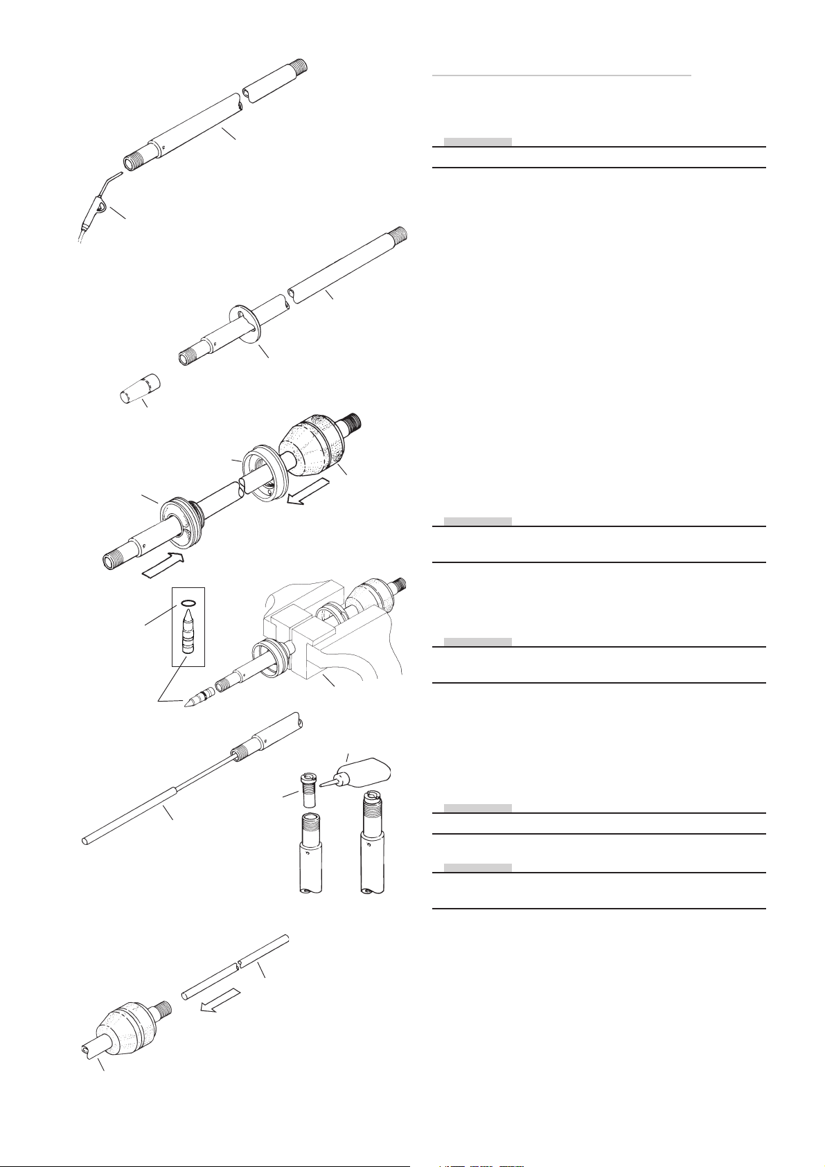
Reassembling the piston shaft
3:3
Seal head
O-ring
Adjuster
needle
3:1
Pressure
air gun
Fitting sleeve
1785-xx
3:7
Tool 1748-01
3:4
End
cap
Piston shaft
3:4
Spacer
3:6
Nozzle
Piston shaft
Bump rubber
Soft jaws
727-xx
Loctite 222
3:8
3:5
3:1
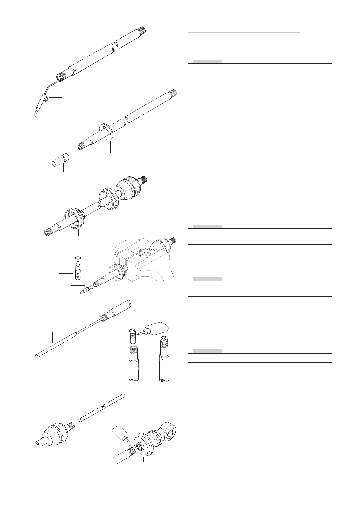
Blow the piston shaft clean with compressed air.
NOTE!
Apply Öhlins red grease (146-01) to all o-rings and seals.
3:2
Check the spec.card to see whether spacers are to be
used on the piston shaft. If so, mount these before fitting
the seal head assembly.
3:3
Use fitting sleeve (1785-xx) to protect the seal in the seal
head assembly.
3:4
Lubricate the piston shaft with shock absorber fluid so
that the seal head assembly slides on easily.
3:5
Put on the end cap and the bump rubber.
3:6
Grip the piston shaft with soft jaws 727-xx.
Fit the O-ring on the adjustment needle. Apply plenty of
red grease on the O-ring so that the needle slides easily
into the piston shaft.
NOTE!
Always ensure that the correct needle is used in relation
to the nozzle.
3:7
Press the needle down, using the tool 1748-01, until it
comes to a stop.
NOTE!
If the seating in the nozzle is chamfered, the nozzle must
be replaced with one without chamfer.
3:8
Carefully tighten the nozzle. Use Loctite 222.
3:9
Apply a little red grease to the adjustment rod and insert
it into the piston shaft from the top.
NOTE!
Ensure that the thread on the piston shaft is free from oil.
Piston shaft
NOTE!
Regardings 12 mm shaft, see page 27, chapter shock
absorber 36.
3:9
Adjustment rod
7
Page 8
3:11
Stop washer
3:13
Compression
side shims
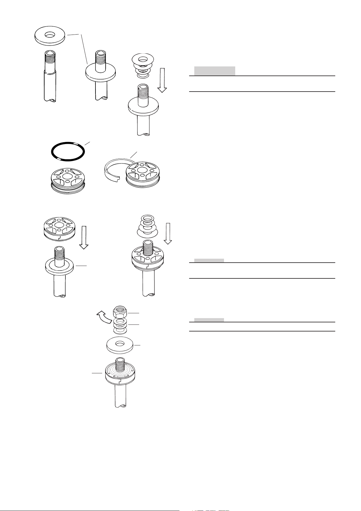
Mounting of piston on piston shaft
and fitting shims
3:10
Grip the end eye in a vice. Use soft jaws.
CAUTION!
The chamfered side of the stop washer must face away
from the lock nut.
3:11
Put the stop washer in position.
3:12
Check shims and replace if necessary.
3:16
Piston
30 Nm
O-ring
3:15
519-xx
3:17
Teflon band
Rebound
side shims
Lock nut
Washer
3:13
Place shims on the compression side according to the
spec. card.
3:14
Ensure that the correct piston is beeing used. If a flat
piston is used face the piston using 1200 abrasive paper
to ensure a completely even and flat surface. Ensure that
there are no burrs or particels on the piston or in the fluid
ducts.
3:15
Where applicable, fit the O-ring underneath the Teflon
band on the piston. Mount the piston ring.
3:16
Put the piston on the piston shaft.
NOTE!
Ensure that the piston faces the correct way. The grooved
side of the piston must face the nut.
3:17
Fit the shims on the rebound side. Carefully check the
spec.card to see which washer (519- xx) is to lie on the
top shim.
NOTE!
There are several different types of 519-xx washers.
519-xx
3:18
Stop
washer
3:18
Refit the stop washer, the washers and the lock nut, torque
tighten to 30 Nm.
8
Page 9
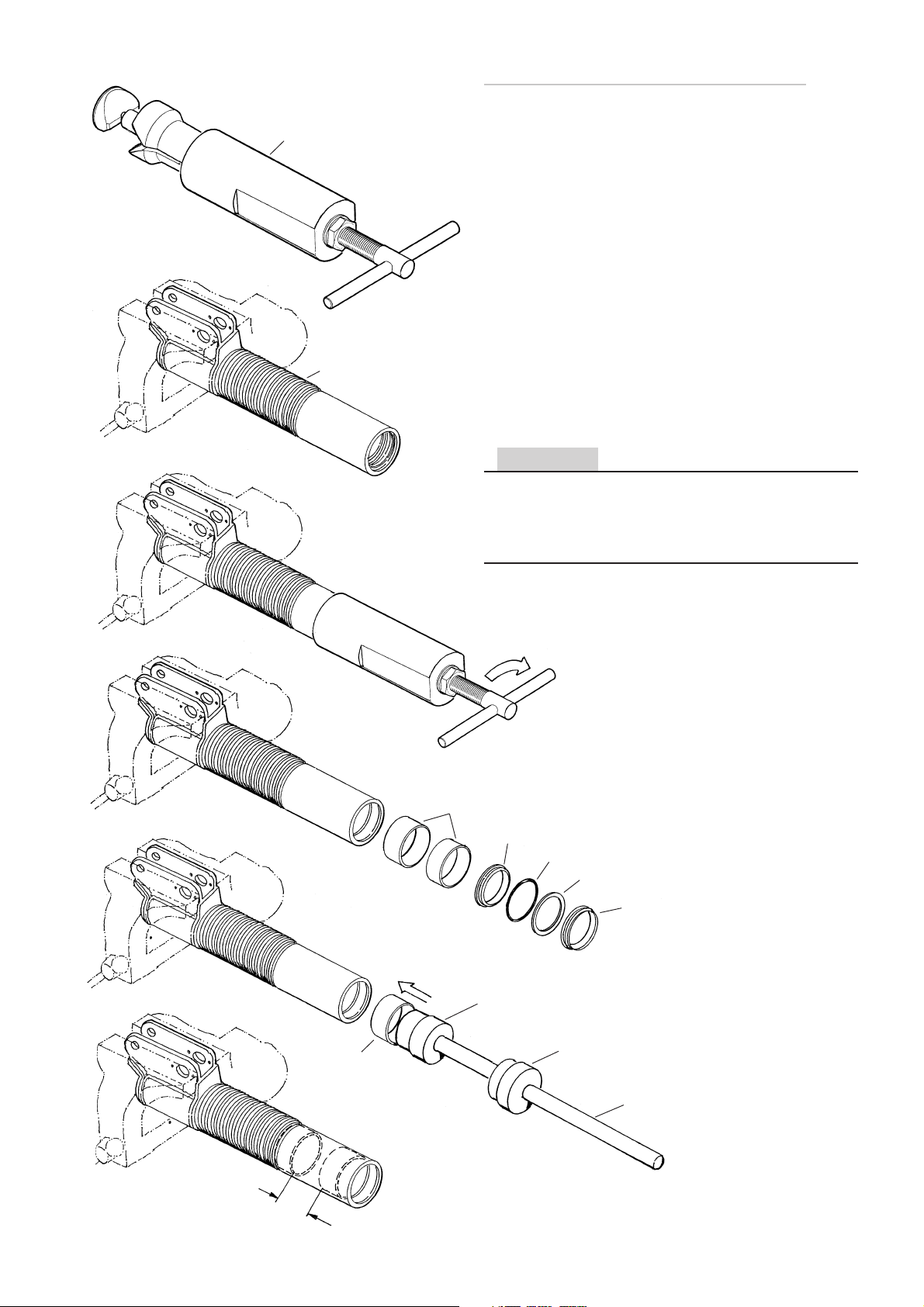
Changing of bushings in the strut.
4:1
4:2
Tool
1828-01
Strut
4:1
Fasten the strut in a vice horizontally. Use Bushing removal
tool 1828-01 ( ø50-ø54 only).
4:2
Push the tool into the lower bushing, fix it and pull the
bushing out together with the upper bushing, the scrapers and the support ring. (and o-rings when frequent)
4:3
Clean the strut carefully and reinstall the bushings. Use
attachment bar 1757-01, installing sleeve 1759-xx and
guide ring 1758-xx. Start with the lower bushing and push
it down all the way to the seat.
4:4
The upper bushing should be pushed down so it is 100
mm above the lower bushing. Apply some locking fluid
Loctite 601 or similar before installing them.
CAUTION
Heat the strut up with a heat air gun, before the installation is made. Be careful to get the bushings straight. Put
the shock absorber cylinder into the strut and check the
function to make sure that the bushings are installed in a
correct way.
4:4
4:3
4:3
4:5
Refit the scrapers and the support ring.
Pull the bushings out
by turning clockwise
Bushings
Seal
Circlip
Support ring
Scraper
Installing sleeve
100 mm
Bushing
Guide ring
Attachment bar
9
Page 10
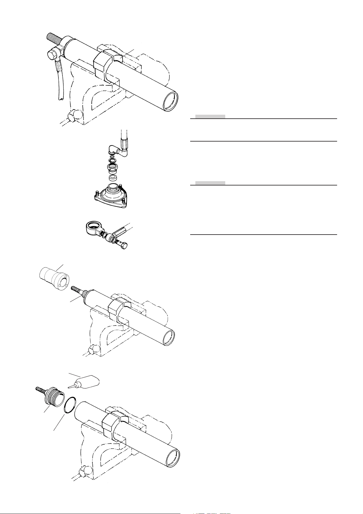
4:6
Hose connections
Tool 1808-01, 02
4:7
Removal and refitting of the cylinder head
4:6
Fasten the cylinder body in a vice horizontally. Again use
tools 1808-01 or 1808-02.
4:7
Remove the hose connection.
4:8
Loosen and remove the Cylinder head. Use tool 1807-01
and a breaker bar.
NOTE!
The thread on the cylinder head is fixed with Loctite 648.
This makes it necessary to use a heat air gun to heat the
cylinder head before it is unthreaded.
4:9
When refitting the cylinder head it is of vital importance
to use Loctite again.
NOTE!
1807-01 for cylinder head 5188 and 5594.
1857-01 for cylinder head Mc Pherson ø40 together with
sleeve 5991-01 for cylinder head 5911-03 and 5911-04.
1857-01 for cylinder head Mc Pherson ø40 together with
sleeve 5991-02 for cylinder head 5911-01 and 5911-02
Cylinder head
Loctite
Cylinder
head
O-ring
Tool 1807-01
4:8
4:9
10
Page 11
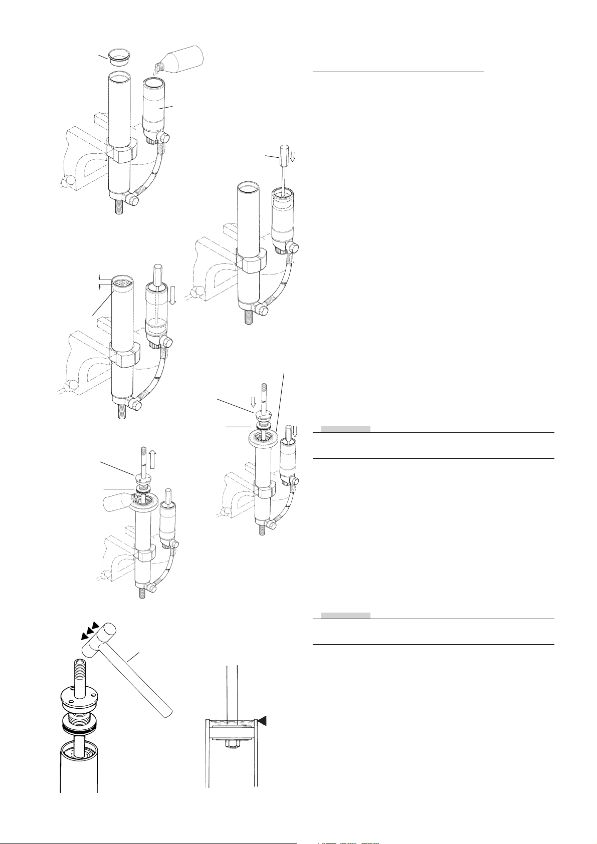
5:1
Plastic
plug
Reservoir
Tool 0720-02
Assembling of
McPherson shock absorber
5:1
Insert a plastic plug (764-01) in the cylinder tube. Fill up
with Öhlins fluid all the way to the edge of the reservoir.
5:2
Push the dividing piston, with teflon band and O-ring fitted,
down in to the reservoir without allowing it to be pressed
back over the circlip groove, make sure that there is no air
between the piston and the oil.
10 mm
Circlip
groove
End cap
Seal head
assembly
5:3
5:5
5:2
End cap
Seal head
assembly
5:4
Retainer
fluid cap
5:3
Push the dividing piston to the bottom, using tool 720-02.
Close the compression adjuster.
Measure the distance from the edge of the reservoir to
the upper edge of the dividing piston and make a note of
the lenght. Fill the cylinder tube with Öhlins fluid to about
10 mm below the circlip groove.
5:4
Install an fluid retainer cup. Insert the piston shaft into the
cylinder tube. Take care, that fluid does not squirt up.
When the piston is submerged in the fluid the piston shaft
should be pressed down hard, to force out air between
the shims and piston.
5:5
Wait a while to allow air bubbles to rise to the surface.
Pull the piston shaft up a bit, without allowing the bleed
holes to come above the surface. Top up with more fluid
if required.
NOTE!
This labour forces fluid through the apertures of the main
piston and helps to bleed out all air.
5:6
Repeat this procedure until all air is expelled. If the shims
are very hard, a check can be made by pushing down the
piston rod very hard. If there is still air remaining the fluid
level will move. If so, strike the piston shaft end firmly
with a plastic hammer to make the shims open.
5:6
Plastic
hammer
5:7
When all air has been expelled, pull the piston shaft up as
far as possible without the bleed holes in the piston shaft
coming above the surface of the fluid. Top up with fluid
all the way up to the edge of the cylinder tube.
NOTE!
Rotate the piston shaft lightly to seat the teflon band properly against the body tube bore.
5:7
Fluid
level
11
Page 12
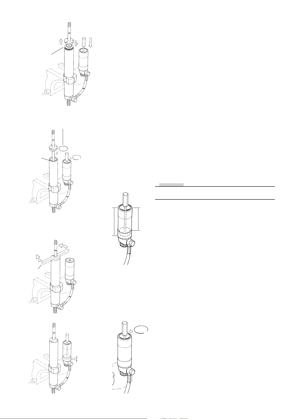
Seal head
assembly
5:8
Retainer ring
Dividing piston
completely down
5:8
Push the seal head down against the fluid and carefully
down to the O-ring groove make sure that the bleedhole
is facing away from you. Then push the piston shaft down
halfway. Make sure that the dividing piston is completely
down to the bottom of the reservoir.
5:9
Open the compression valve and, using a blunt screwdriver, push the seal head assembly down until the circlip
groove is visible.
5:10
Fit the circlip and pull up the piston shaft up, make sure
that the circlip is fixed in its groove and in the seal head
assembly groove.
5:11
Fit the end cap with tool 1858-01. Apply red grease 146-01.
Tighten to 50 Nm.
5:9
Circlip
groove
Tool
1858-01
5:10
5:12
5:12
With the piston shaft fully out measure again from the
edge of the reservoir to the upper edge of the dividing
piston. If the value between the first and the second
measurement is more than 7 mm or less than 4 mm, open
the filling screw and adjust the position of the dividing
piston carefully, if the piston is too far in top up with fluid
in filling hole. Then screw in the filling screw.
5:13
NOTE!
Put the dividing piston in correct position according to
table.
5:13
Reservoir Position
L
P
length (L) of dividing piston (P)
80 47
90 57
110 77
120 87
133 100
150 117
180 147
220 187
5:11
7-10 mm
5:14
5:14
Fit the O-ring on the reservoir cap assy, apply some red
grease on the O-ring and push it into the chamber using
tool 720-03. Fit the circlip make certain that it enters its
groove properly.
12
Page 13
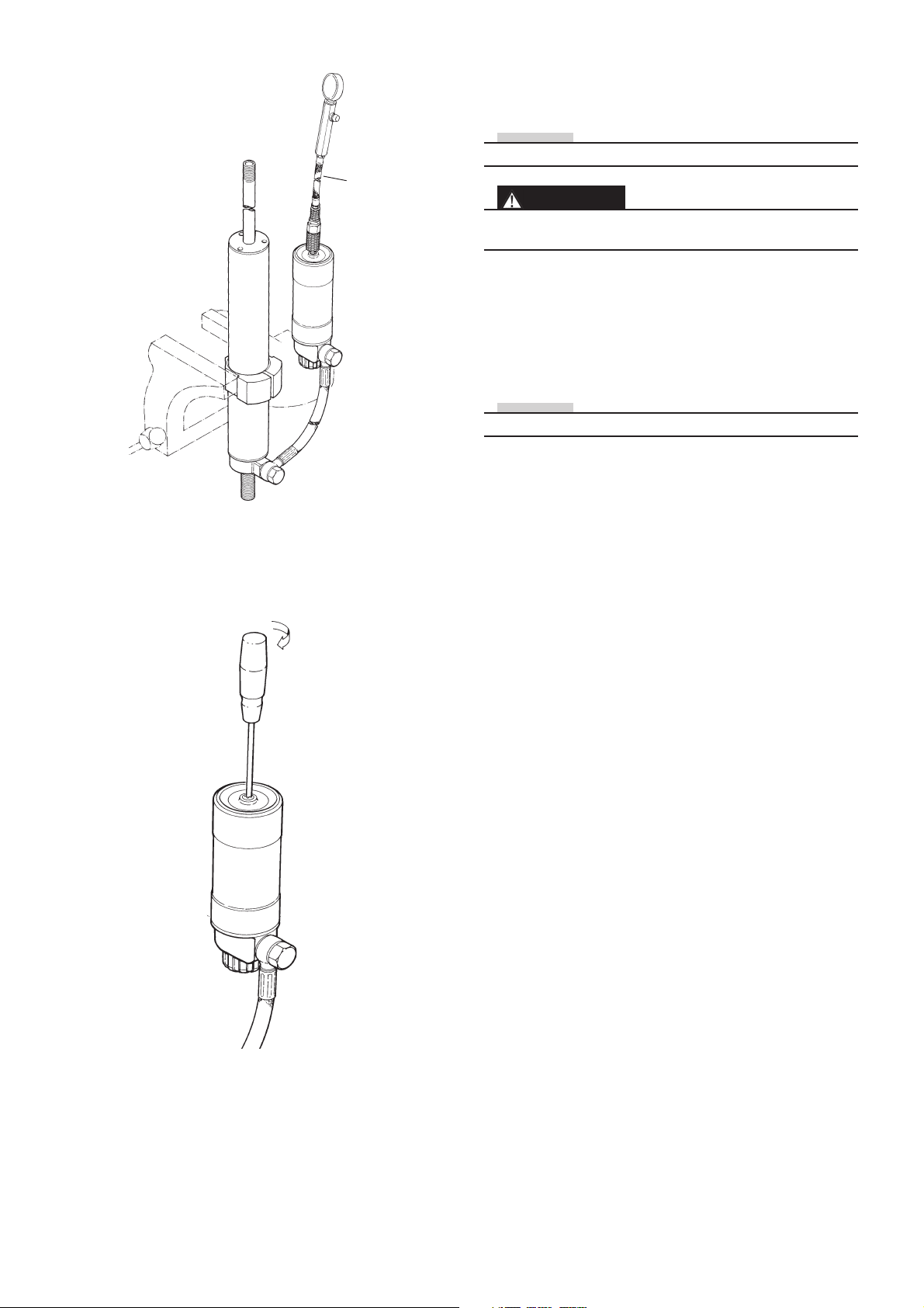
Pressurising and assembling protective
cover on the cylinder
5:15
Gas filling tool
1781-01
NOTE!
Nitrogen (N2) gas . Use pressure gauge (1781-01).
WARNING!
Use of inflammable gas for pressurising the shock
absorber can be hazardous. Use nitrogen gas (N2) only.
5:15
Check the gas pressure stipulated in the spec.card. Dip
the needle of the gas tool (1781-01) in red grease and
insert the needle through the gas filler valve.
Charge with gas to the correct pressure, according to the
spec.card.
NOTE!
Ensure that there is no leakage of gas or fluid.
5:16
Screw in the gas filler screw with O-ring.
5:16
13
Page 14

Shock absorber 46
Contents
Shock absorber 46 .................................................. 15
Dismantling the shock absorber ................................ 16
Dismantling the piston shaft ...................................... 18
Reassembling the piston shaft .................................. 19
Cylinder head............................................................ 21
Assembling the shock absorber ................................ 22
External reservoir ...................................................... 23
End piece on reservoir .............................................. 24
Seal head assembly .................................................. 24
Spring assembly ....................................................... 26
Shock absorber 36 .................................................. 27
General .................................................................... 43
Drawings ................................................................. 55
14
Page 15
1:3
Tool
773-01
Screw and
O-ring
1:4
Injection
needle
Dismantling the shock absorber
1:1
Remove the spring, use tool 747-01.
Use correct tool to avoid damages.
1:2
Clean the shock absorber carefully externally and inspect
for damages.
1:3
Fasten the shock absorber use tool 773-01. Remove the
screw and o-ring from the reservoir end cap
(Shock absorber head on shock absorber models without
external reservoir.)
NOTE!
Before the gas pressure is relieved the adjuster settings
must be counted and noted. Even check that the gas
pressure is correct. Following that, the adjusters should
be set in a fully open position.
1:4
Relieve the nitrogen gas pressure by inserting an injection
needle into the shaft through the valve rubber.
WARNING
Releasing high pressure gas from the shock absorber can
be hazardous. Do not perform any kind of service until
gas pressure is completely released.
Tool 765-01
NOTE!
Cylinder head
Adjustable
wrench
1:5
Remove the end cap from the shock absorber body. Use
a chisel and a hammer.
NOTE!
Shock absorbers type D ( Internal dividing piston) must
have their cylinder head removed. The cylinder tube is
fitted in a vice with tool (765-01). Heat the head with a
heatgun and use a adjustable wrench to remove it.
1:6
Depress the seal head approximately 15 mm.
1:7
Release and remove the circlip from the cylinder tube
with tool 715-01 or a similar tool. If necessary remove
burrs from the circlip groove with a riffer.
15
Page 16
1:8
Circlip
1:8
Push the end cap of the reservoir down into the reservoir,
use tool 720-03, remove the circlip. Remove the end cap.
1:9
End cap
O-ring
Reservoir
Measure pin
1:10
1:9
Fit a measure pin to the dividing piston.
1.10
Lower the oil level by pulling the reservoir dividing piston
outwards by help of the measure pin and by pulling the
shaft outwards.
1:11
Pull the shaft assembly up carefully and remove it from
the cylinder tube.
1:12
Remove the dividing piston and drain the shock absorber
from oil.
1:13
Remove all o-rings and seals.
1:14
Clean all parts carefully.
1:11
End cap
Seal head
assembly
Teflon band
1:12
Dividing piston
O-ring
16
Page 17
2:3
Piston band
Dismantling the piston shaft assembly
2:1
Fasten the shaft assembly in a vice with soft jaws. Use
clamping tool (727-xx)
2:4
Lock nut
Washer
Rebound
shims stack
Piston
Compression
shims stack
Washer
NOTE!
The following text (2:2 and 2:3) is related to shock
absorbers of PDS type only.
2:2
Remove the lock nut (13 mm key)of the PDS piston and
remove the washer. Remove the upper shims stack, the
piston and the lower shim stack. Remove the stop washer
and loosen the PDS piston holder (13 mm key).
NOTE!
Put the shim stack aside and place the shims in the same
order as they were fitted on piston holder.
2:3
Remove teflon band of the damper piston
2:4
Remove the lock nut (already done on PDS model), the
rebound shims stack, the damper piston and the
compression shim stack.
NOTE!
Put the shim stack aside and place the shims in the same
order as they were fitted on shaft.
2:5
Seal head
End cap
Piston shaft
Bump rubber
Adjustment pin
2:5
Remove all the other parts from the shaft and put them
aside in correct order.
2:6.
Remove the end eye, use a heatgun.
Remove the adjustment valve jet, the adjustment needle
and the adjustment pin.
2:7
Clean all parts carefully and inspect for wear or damage.
Check the o-ring of the needle and replace if necessary.
2:8
Inspect the shaft for bends and scratches.
2:9
Replace piston ring, o-rings and lock nut.
2:10
If necessary replace bump rubber, scraper ring and cap,
seal head assembly and eventual other defect parts.
2:6
Piston shaft
Needle
Valve jet
17
Page 18
LOCTITE
3:3
3:1
Pressure
air gun
Piston shaft
Spacer
3:2
Reassembling the piston shaft
3:1
Blow the piston shaft clean with compressed air.
NOTE!
Apply Öhlins red grease (146-01) to all o-rings and seals.
3:2
Check the spec.card to see whether spacers are to be
used on the piston shaft. If so, mount these before fitting
the seal head assembly.
3:3
Use fitting sleeve (1785-02) to protect the seal in the seal
head assembly.
3:4
Lubricate the piston shaft with shock absorber fluid so
that the seal head assembly slides on easily.
Fitting sleeve
1785-01
O-ring
Adjustable
needle
Tool 1748-01
3:4
Seal head
3:7
End cap
Nozzle
3:5
Bump rubber
3:6
loctite 222
3:8
3:5
Put on the end cap and the bump rubber.
3:6
Grip the piston shaft with soft jaws 727-xx.
Fit the O-ring on the adjustment needle. Apply plenty of
red grease on the O-ring so that the needle slides easily
into the piston shaft.
NOTE!
Always ensure that the correct needle is used in relation
to the nozzle.
3:7
Press the needle down, using the tool 1748-01, until it
comes to a stop.
NOTE!
If the seating in the nozzle is chamfered, the nozzle must
be replaced with one without chamfer.
3:8
Carefully tighten the nozzle. Use Loctite 222.
3:9
Apply a little red grease to the adjustment rod and insert
it into the piston shaft from the top.
NOTE!
Ensure that the thread on the piston shaft is free from oil.
Piston shaft
Adjustment rod
3:9
Loctite 270
3:10
End eye
Mounting the end eye.
3:10
Use Loctite 270 on the piston shaft thread, screw the end
eye on and tighten using an adjustable wrench.
Tightening torque: See page drawings for correct torque.
18
Page 19
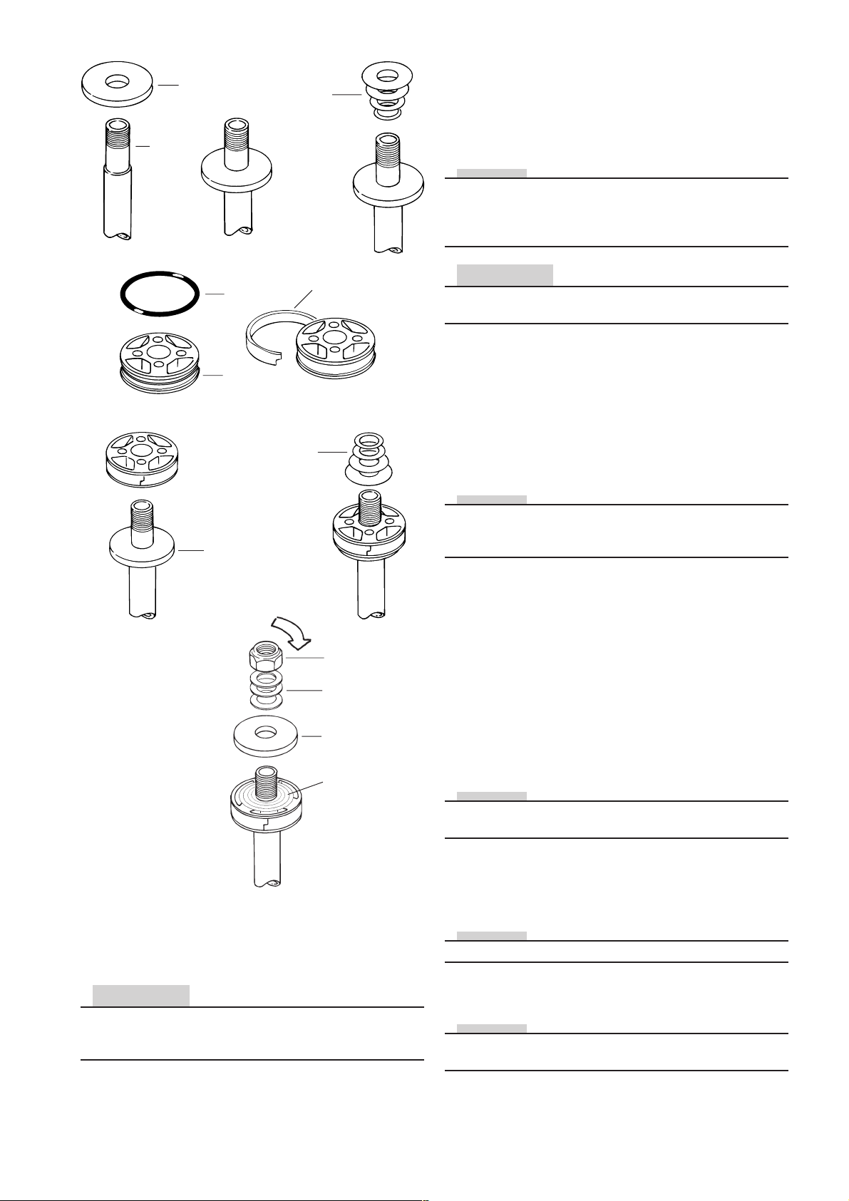
Piston
shaft
3:12
Stop washer
Compression
shims
3:14
Mounting of piston on piston shaft
and fitting shims
3:11
Grip the end eye in a vice. Use soft jaws.
Put the “top out” spring in position, if one is beeing used.
NOTE!
Always ensure that the correct spring is used. Check also
that the spring does not protrude too far above the sleeve.
There is a risk that the sleeve will slide down when tightening the shims nut.
3:17
3:16
3:19
O-ring
Piston
519-xx
30 Nm
Teflon band
Rebound
shims
3:18
Lock nut
Washer
Stop washer
519-xx
Shim stack
CAUTION!
The chamfered side of the stop washer must face away
from the lock nut.
3:12
Put the stop washer in position.
3:13
Check shims and replace if necessary.
3:14
Place shims on the compression side according to the
spec. card.
NOTE!
Make sure to put the shims in right order and that the
shims are in correct position to the piston. (See spec.
card)
3:15
Ensure that the correct piston is beeing used. If a flat
piston is used face the piston using 1200 abrasive paper
to ensure a completely even and flat surface. Ensure that
there are no burrs or particels on the piston or in the fluid
ducts.
3:16
Where applicable, fit the O-ring underneath the Teflon
band on the piston. Mount the piston ring.
3:17
Put the piston on the piston shaft.
NOTE!
Ensure that the piston faces the correct way. The grooved
side of the piston must face the nut.
3:20
Fit the PDS piston holder and tighten it to 30 Nm. Fit the
stop washer, the lower shim stack, the piston and the
upper shim stack. Use cleaner to make the shims dry, so
they do not rotate during assembly work.
CAUTION!
It is of great importance that the triangular shims are in
correct position when the PDS piston assembly is
mounted. Check from both sides.
3:21
Put the washer and lock nut back to the PDS holder and
tighten to 18 Nm.
3:18
Fit the shims on the rebound side. Carefully check the
spec.card to see which washer (519- xx) is to lie on the
top shim.
NOTE!
There are several different types of 519-xx washers.
3:19
Refit the lock nut, torque tighten to 30 Nm.
NOTE!
The following text (4.10-4.11) is related to shock absorbers of PDS type only .
19
Page 20
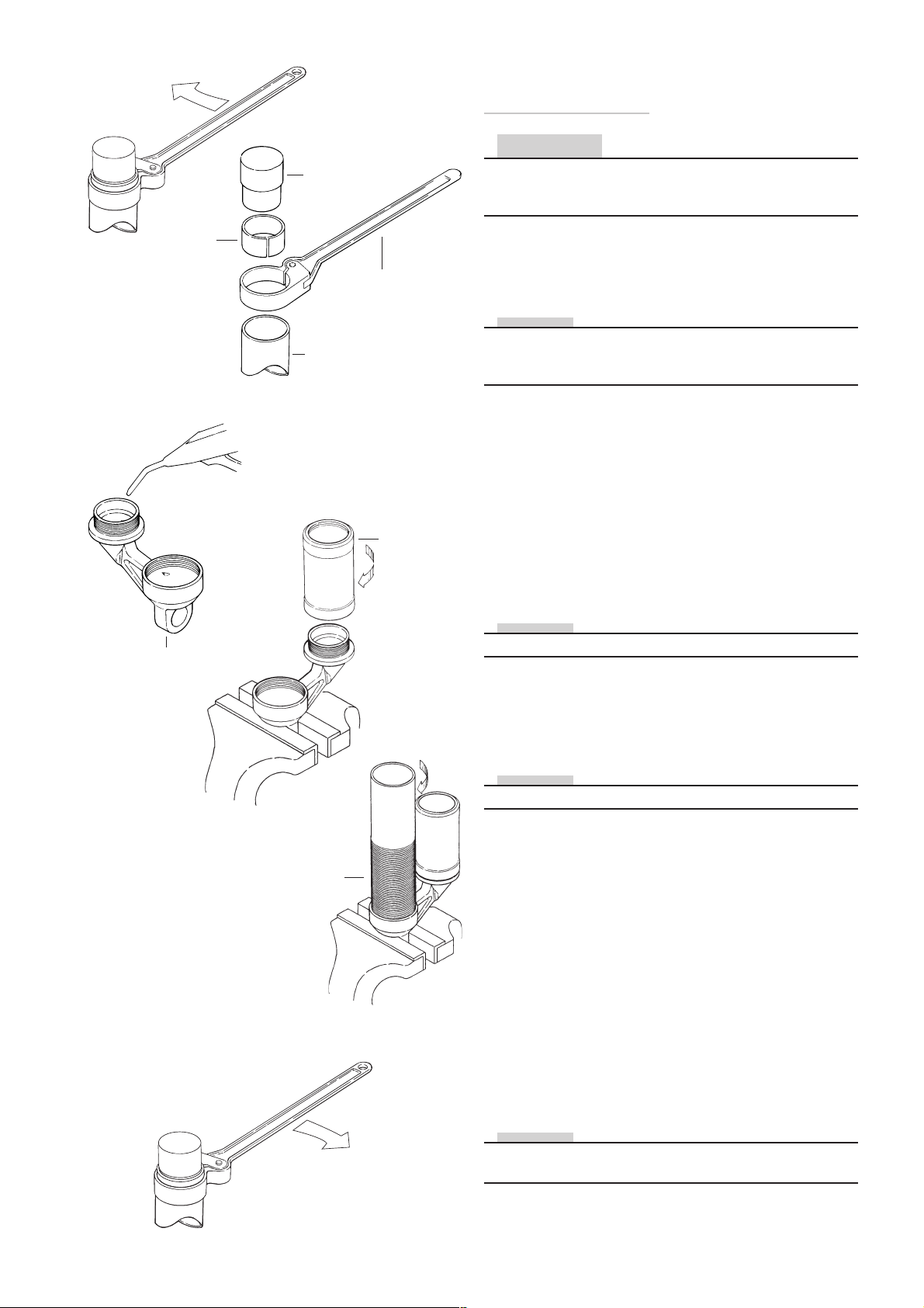
4:1
Insert tool 1798-01
Removing and refitting
the cylinder head
CAUTION!
Removing the cylinder head is only carried out on shock
absorbers with internal dividing piston (D) or when the
cylinder tube or reservoir tube must be changed.
Sleeve
737-xx
Cylinder head
4:4
Cylinder tube
Compressed air
Tool 738-01
Reservoir
4:5
4:7
4:1
Grip the shock absorber head in the vice with soft jaws.
Use tool (738-01) in combination with sleeve (737-xx) and
insert tool (1798-01) to loosen the cylinder tube.
NOTE!
The cylinder head is fastened with Loctite. It is necessary
to heat the surfaces near the threads to remove the
cylinder tube and the reservoir tube. Use a heat air gun.
4:2
Use tool (738-01) in combination with sleeve (737-xx) to
loosen the reservoir
4:3
Screw cylinder tube and reservoir out by hand. Remove
and waste the O-rings from the cylinder head
4:4
Blow the shock absorber head clean with compressed
air. Ensure that there are no particles left in the ducts.
Apply red grease to new O-rings. Fit new O-rings.
NOTE!
Ensure that the correct O-rings are beeing used.
4:5
Grip the shock absorber head in the vice with soft jaws,
screw the gas reservoir in position by hand. Make certain
that the O-ring has not been damaged. Tighten the reservoir using tool 738-01 and sleeve (737-xx).
NOTE!
Tighten using moderate force.
6:5
Shock
absorber body/
Cylinder tube
210 Nm
4:6
A retainer ring (533-01) is used on some cylinder tubes.
Loctite is not necessary if a retainer ring is used. Otherwise use Loctite 542.
4:7
Screw the cylinder tube to the bottom and check that the
O-ring has not been damaged.
4:8
Tighten the cylinder tube using tool 738-01 and sleeve
737-01 insert tool 1798-01 in the cylinder tube to prevent
deformation when tightening. Torque tighten to 210 Nm.
If a lock nut is used, tighten it with tool 743-01.
4:9
Screw in the filler screw with the O-ring.
NOTE!
If an oil filling machine is beeing used, the O-ring and
screw are not to be fitted at this moment.
20
Page 21
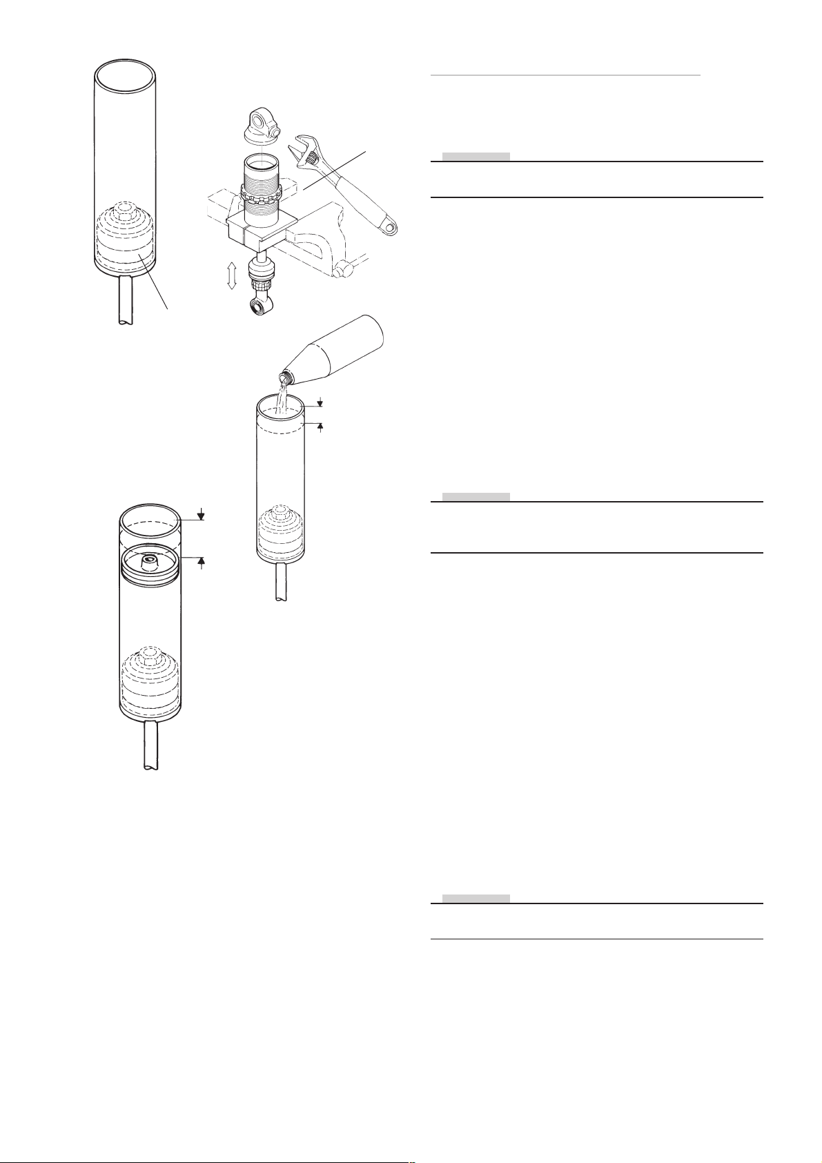
5:5
Assembling the shock absorber
Piston shaft
assembly
5:10
see
spec.
card
5:6
15 mm
5:7
Tool
0765-01
5:1
Fasten the shock absorber in tool 773-01
NOTE!
Apply Öhlins red grease 146-01 to all o-rings and seals
and a thin layer to the inside of the cylinder tube.
Shock absorber emulsion type only
5:2
Fill the cylinder tube with Öhlins oil to the recommended
oil level. See spec.card.
5:3
Make sure that the adjustment needle is fully open before
installing the piston shaft. Install the piston shaft assembly into the cylinder tube.
5:4
Install the circlip and make sure it is properly seated before
the end cap is fixed by knocking it in with a plastic hammer.
NOTE!
Shock absorbers without dividing piston must be pressurised in upright position. I.e. the shock absorber head facing upwards.
5:10
Install the dividing piston into the cylinder tube and set
the piston position with 757-xx and a vernier.
See spec.card for correct position.
5.11
Install the centre screw and use tool 757-xx to hold the
dividing piston when tightening the screw. Wipe off
eccesive oil.
Shock absorber
with internal dividing piston type D
5:5
Make sure that the needle is fully open before installing
the piston shaft. Install the piston shaft assembly into the
cylinder tube. Install the seal head, circlip and and make
sure it is properly seated before the end cap is fixed by
knocking it in with a plastic hammer.
5:6
Turn the cylinder tube so the piston shaft is facing downwards. Use tool 765-01 to hold the tube in the vice.
5:7
Fill the cylinder tube with Öhlins oil ( to approximately 15
mm from the top of the tube. Bleed out remaining air by
slowly moving the piston shaft up and down in the cylinder tube. Do not push hard, just move the the shaft slowly.
NOTE!
To obtain maximum oil volume, pull the shaft out to fully
extended length before installing the dividing piston
.
5:8
Inspect the dividing piston for wear or damage.
5:12
Clean the cylinder tube thread with cleaner and use Loctite
270 on the thread when installing in the cylinder head.
Turn the tube body around and fasten the cylinder head
in a vice with soft claws. Use tools 737-xx and 738-01 to
tighten the body tube
5:9
Replace o-rings and piston rings with new.
Use Öhlins grease 146-01 on all o-rings and seals.
21
Page 22
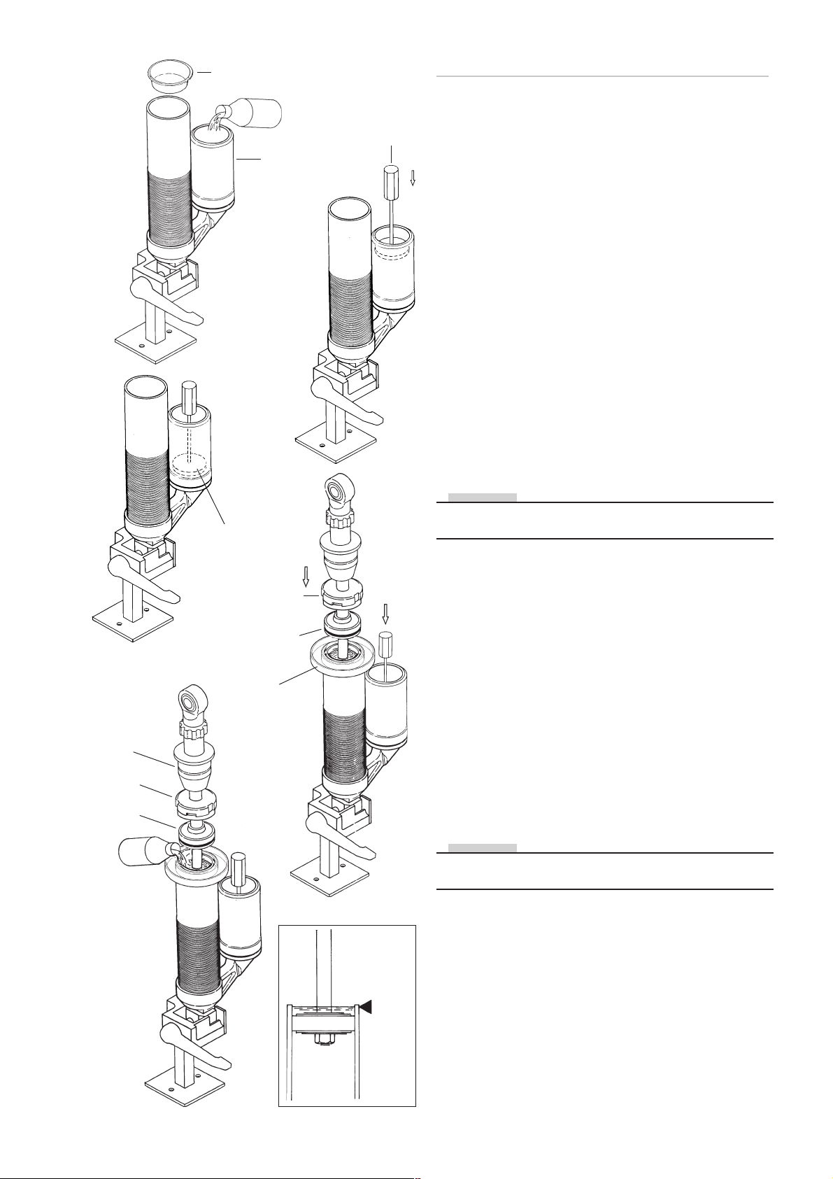
6:1
Lid 764-01
Reservoir
Tool
720-02
Shock absorber with external reservoir
6:1
Insert a plastic plug (764-01) in the cylinder tube. Fill up
with Öhlins fluid all the way to the edge of the reservoir.
6:2
Push the dividing piston, with teflon band and O-ring fitted, down in to the reservoir without allowing it to be
pressed back over the circlip groove, make sure that there
is no air between the piston and the oil.
6:3
Bump
rubber
End cap
Seal head
assembly
Dividing piston in
bottom position
End cap
Seal head
assembly
Fluid
retainer cup
6:2
6:4
6:3
Push the dividing piston to the bottom, using tool 720-02.
Close the compression adjuster.
Measure the distance from the edge of the reservoir to
the upper edge of the dividing piston and make a note of
the lenght. Fill the cylinder tube with Öhlins fluid to about
10 mm below the circlip groove.
6:4
Install an fluid retainer cup. Insert the piston shaft into the
cylinder tube. Take care, that fluid does not squirt up.
When the piston is submerged in the fluid the piston shaft
should be pressed down hard, to force out air between
the shims and piston.
NOTE!
This labour forces fluid through the apertures of the main
piston and helps to bleed out all air.
6:5
Wait a while to allow air bubbles to rise to the surface.
Pull the piston shaft up a bit, without allowing the bleed
holes to come above the surface. Top up with more fluid
if required.
6:6
Repeat this procedure until all air is expelled. If the shims
are very hard, a check can be made by pushing down the
piston rod very hard. If there is still air remaining the fluid
level will move. If so, strike the end eye firmly with a plastic hammer to make the shims open.
6:7
When all air has been expelled, pull the piston shaft up as
far as possible without the bleed holes in the piston shaft
coming above the surface of the fluid. Top up with fluid
all the way up to the edge of the cylinder tube.
NOTE!
Rotate the piston shaft lightly to seat the teflon band properly against the body tube bore.
6:5
6:5
Fluid
level
22
Page 23
End cap
Seal head
assembly
7:1
Retainer
ring
7:2
Mounting the seal head assembly and
end piece on reservoir
7:1
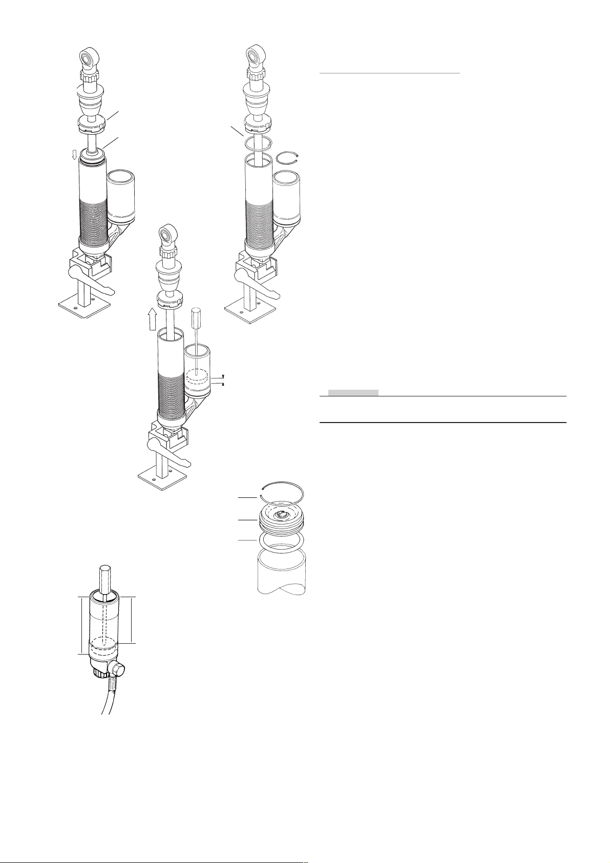
Push the seal head down against the fluid and carefully
down to the O-ring groove make sure that the bleedhole
is facing away from you. Then push the piston shaft down
halfway. Make sure that the dividing piston is fully down
to the bottom of the reservoir.
7:2
Open the compression valve and, using a blunt screwdriver, push the seal head assembly down until the circlip
groove is visible.
7:3
Fit the circlip and pull up the piston shaft up, make sure
that the circlip is fixed in its groove and in the seal head
assembly groove. Fit the end cap by tapping it in with a
plastic hammer.
7:3
Reatainer ring (circlip)
7:4
7-10 mm
End cap
O-ring
7:5
7:4
With the piston shaft fully out measure again from the
edge of the reservoir to the upper edge of the dividing
piston. If the value between the first and the second
measurement is more than 7 mm or less than 4 mm, open
the filling screw and adjust the position of the dividing
piston carefully, if the piston is too far in top up with fluid
in filling hole. Then screw in the filling screw.
NOTE!
Put the dividing piston in correct position according to
table.
Reservoir Position
length of dividing piston
80 47
90 57
110 77
120 87
133 100
150 117
180 147
220 187
7:5
Fit the O-ring on the cap assy, with the aid of red grease
L
P
and push it into the chamber using tool 720-03. Fit the
circlip make certain that it enters its groove properly.
23
Page 24
7:6
Gas filling tool
1781-01
Pressurising and assembling protective
cover on the cylinder
7:6
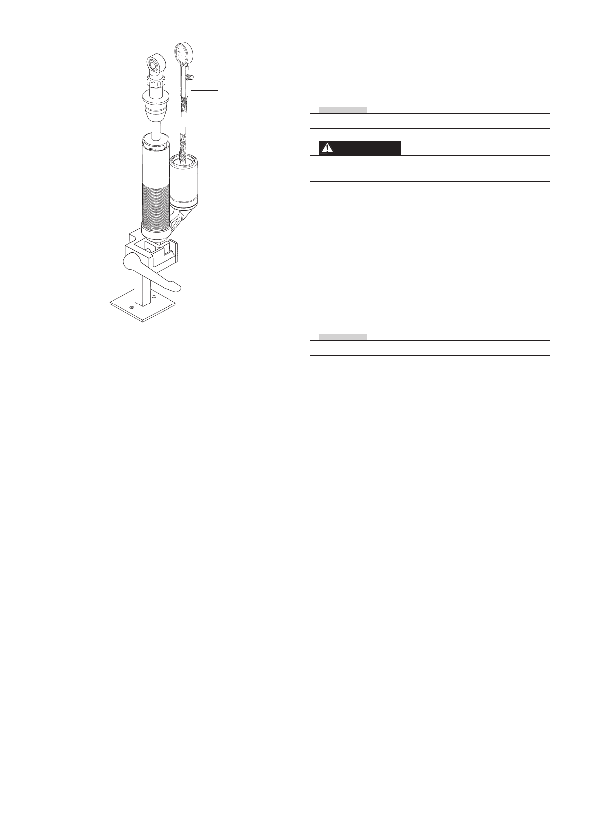
Pressurise the shock absorber according to spec.card.
NOTE!
Nitrogen (N2) gas . Use pressure gauge (1781-01).
WARNING!
Use of inflammable gas for pressurising the shock
absorber can be hazardous. Use nitrogen gas (N2) only.
7:7
Tap the end cap into the cylinder tube gently with a plastic
hammer.
7:8
Check the gas pressure stipulated in the spec.card. Screw
out the gas filler screw and O-ring. Dip the needle of the
gas tool (1781-01) in red grease and insert the needle
through the gas filler valve.
Charge with gas to the correct pressure, according to the
spec.card.
NOTE!
Ensure that there is no leakage of gas or fluid.
7:10
Screw in the gas filler screw with O-ring.
24
Page 25
8:1
Length
8:2
Stroke
Settings and spring assembly
8:1
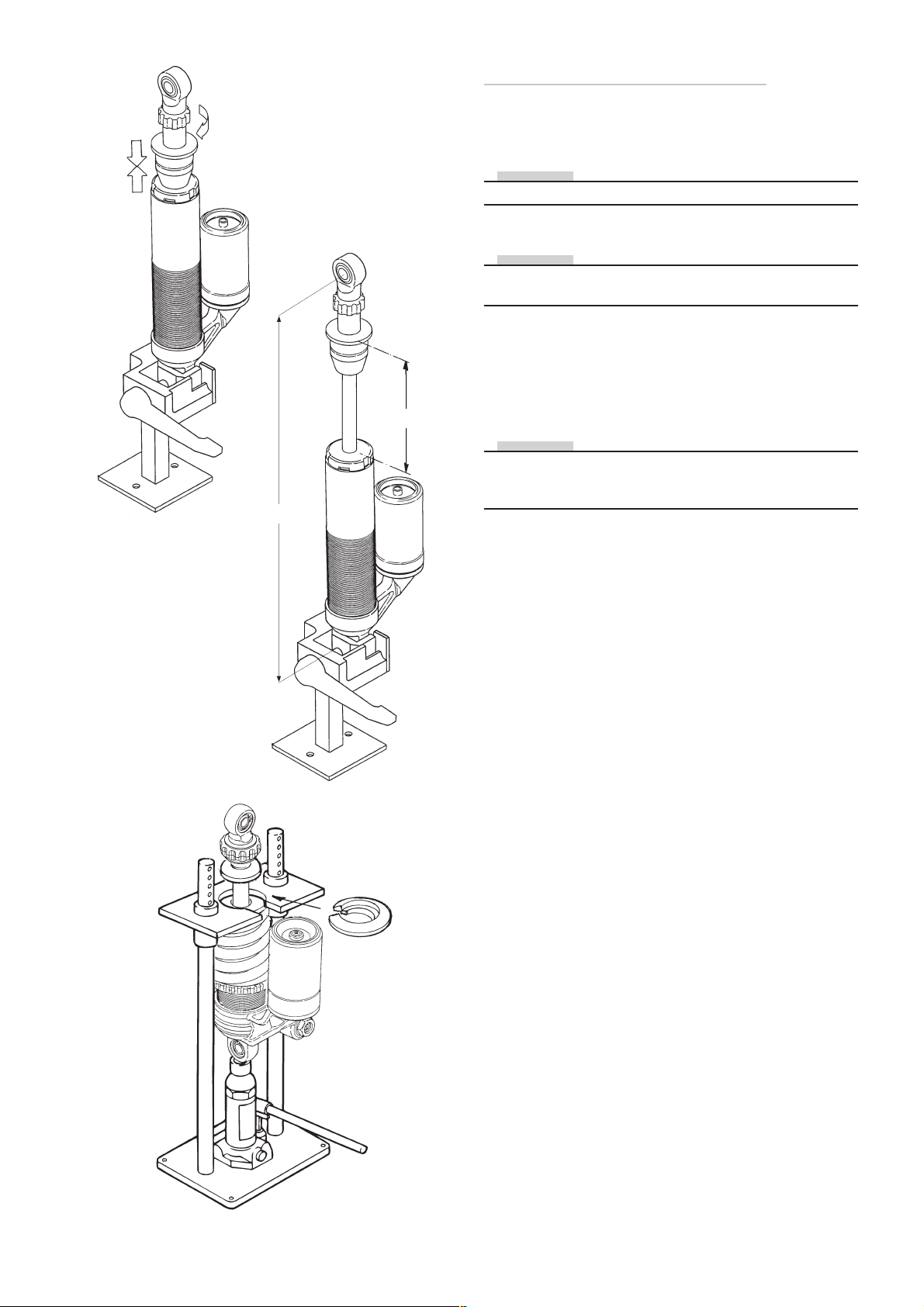
Push the piston shaft down to its bottom position and
close the rebound adjustment fully.
NOTE!
Use your fingers only. No tools may be used.
If everything is correct, the piston shaft should stay down.
NOTE!
Certain shock absorbers are provided with an integrated
“bleed”, causing the piston shaft to move up slowly.
Open the adjustment the number of clicks stated in the
spec.card.
8:2
Measure the length, stroke and compare to spec.card.
Check the free length of the spring.
NOTE!
Shock absorbers with top-out spring will be 3 - 4 mm
shorter than specified length on the spec.card, before the
main spring is fitted.
8:3
8:3
Mount the spring and spring-clip and adjust the preload
rings to the correct preload. See spec. card.
8:4
Measure the overall length and check it against the
spec.card.
25
Page 26

Shock absorber 36
Contents
Shock absorber 36 .................................................. 27
PRC ø14 Dismantling the shock absorber ................. 28
PRC ø12 Dismantling the shock absorber ................. 30
Dismantling the piston shaft assy .............................. 32
Reassembling the piston shaft .................................. 33
Cylinder head............................................................ 35
Assembling the shock absorber ................................ 36
External reservoir ...................................................... 37
Seal head assembly .................................................. 38
End piece on reservoir .............................................. 38
Spring assembly ....................................................... 40
General .................................................................... 43
Drawings ................................................................. 55
26
Page 27
1:3
Screw
O-ring
Gas injection
needle
Dismantling the shock absorber
1:1
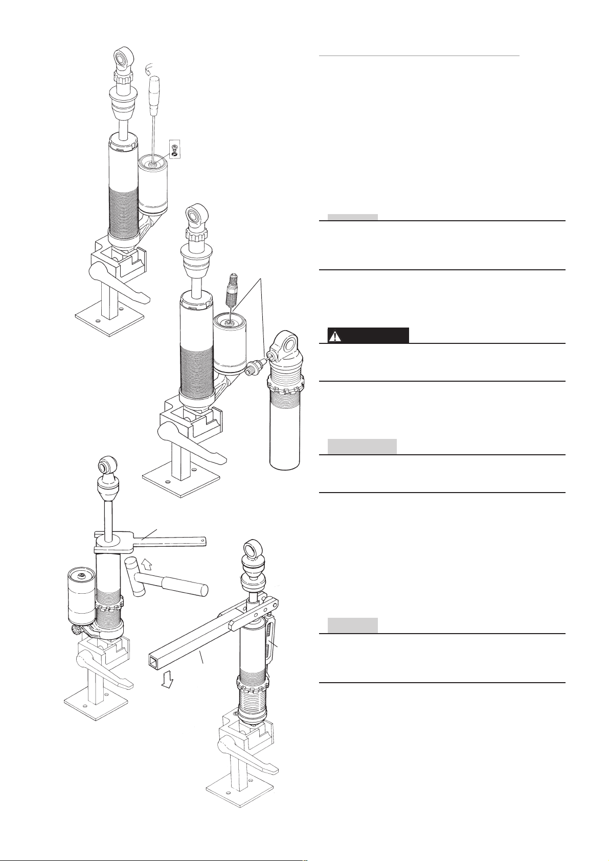
Remove the spring, use tool 747-01.
Use correct spacer to avoid damages.
1:2
Clean the shock absorber carefully externally and inspect
for damages.
1:3
Fasten the shock absorber use tool 773-01. Remove the
screw and o-ring from the reservoir end cap
(Shock absorber head on shock absorber models without
external reservoir.)
NOTE!
Before the gas pressure is relieved the adjuster settings
must be counted and noted. Even check that the gas
pressure is correct. Following that, the adjusters should
be set in a fully open position.
1:4
Relieve the nitrogen gas pressure by inserting an injection
needle into the shaft through the valve rubber.
WARNING
Releasing high pressure gas from the shock absorber can
be hazardous. Do not perform any kind of service until
gas pressure is completely released.
1:5
Tool 704-01
Tool
714-01
1:4
Tool
735-01
1:5
Remove the end cap from the shock absorber body. Use
cap remover tool (704-01).
CAUTION!
36 mm shock absorbers have two circlips that must be
removed. Check carefully and avoid asratching the inner
surface of the shock absorber to avoid leaks.
1:6
Depress the seal head approximately 15 mm. Use (714-
01) and turnbuckle (735-01) on 12 mm shaft. Use a flat
screwdriver on 14 mm shaft.
1:7
Release and remove the circlip from the cylinder tube
with tool 715-01 or a similar tool. If necessary remove
burrs from the circlip groove with a riffer.
NOTE!
Shock absorbers type D ( Internal dividing piston) must
have their cylinder head removed. The cylinder tube is
fitted in a vice with tool (791-01). Heat the head with a
heatgun and use a adjustable wrench to remove it.
1:6
(12mm shaft only)
27
Page 28
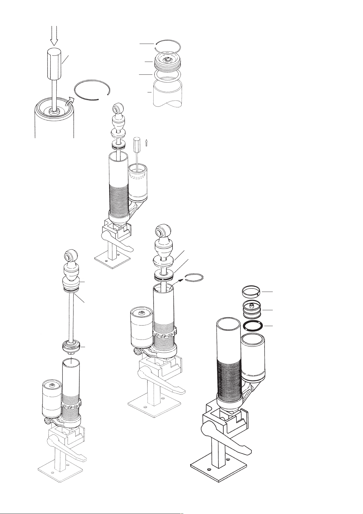
1:8
Tool 720-03
Circlip
Circlip
End cap
O-ring
Reservoir
1:8-2
1:8
Push the end cap of the reservoir down into the reservoir,
use tool 720-03, remove the circlip. Remove the end cap.
(Shock absorbers with external reservoir only).
1:9
Lift up the seal head assembly.
1.10
Lower the oil level by pulling the reservoir dividing piston
outwards by help of the measure pin and by pulling the
shaft outwards.
(Shock absorbers with external reservoir only).
1:11
Remove the lower circlip of the cylinder tube.
1:12
Pull the shaft assembly up carefully and remove it from
the cylinder tube.
1:12
1:10
End cap
Seal head
assembly
Piston
1:13
Drain the shock absorber from oil.
1:14
Remove all o-rings and seals.
1:15
Clean all parts carefully.
1:11
End cap
Seal head assembly
Circlip
1:15
Teflon band
Dividing piston
O-ring
28
Page 29
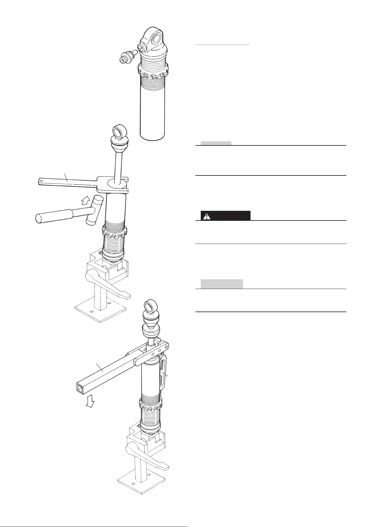
Tool 704-01
2:5
Injection
needle
2:4
Dismantling the shock absorber type D
with ø12 shaft
2:1
Remove the spring, use tool 747-01.
Use correct tool to avoid damages.
2:2
Clean the shock absorber carefully externally and inspect
for damages.
2:3
Fasten the shock absorber use tool 773-01. Remove the
screw and o-ring from the reservoir end cap
(Shock absorber head on shock absorber models without
external reservoir.)
NOTE!
Before the gas pressure is relieved the adjuster settings
must be counted and noted. Even check that the gas
pressure is correct. Following that, the adjusters should
be set in a fully open position.
2:4
Relieve the nitrogen gas pressure by inserting an injection
needle into the shaft through the valve rubber.
Tool 714-01
2:6
Tool
735-01
WARNING
Releasing high pressure gas from the shock absorber can
be hazardous. Do not perform any kind of service until
gas pressure is completely released.
2:5
Remove the end cap from the shock absorber body. Use
cap remover tool (704-01).
CAUTION!
A few shock absorbers have two circlips that must be
removed. Check carefully and avoid scratching the inner
surface of the shock absorber to avoid leaks.
2:6
Depress the seal head approximately 15 mm. Use (714-
01) and turnbuckle (735-01)
2:7
Release and remove the circlip from the cylinder tube
with tool 715-01 or a similar tool. If necessary remove
burrs from the circlip groove with a riffer.
29
Page 30
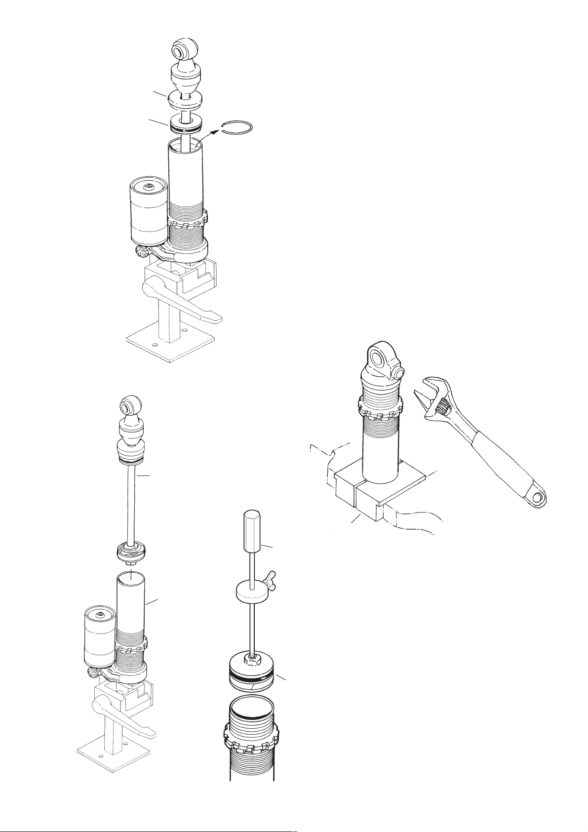
2:8
2:8
Lift up the seal head assembly.
End cap
Seal head
2:9
Circlip
2:9
Remove the lower circlip of the cylinder tube.
2:10
Pull the shaft assembly up carefully and remove it from
the cylinder tube. Use tool 1706-01.
2:11
Drain the shock absorber from oil, and clean all parts
carefully.
2:12
Remove the cylinder head with a adjustable wrench, use
clamping tool 791-01 in a vice to hold the tube.
2:13
Remove the dividing piston, use tool 720-02.
2:12
2:10
Adjuster
wrench
Piston shaft
assembly
2:13
Tool
791-01
Tool
720-02
Cylinder
tube
Dividing
piston
30
Page 31
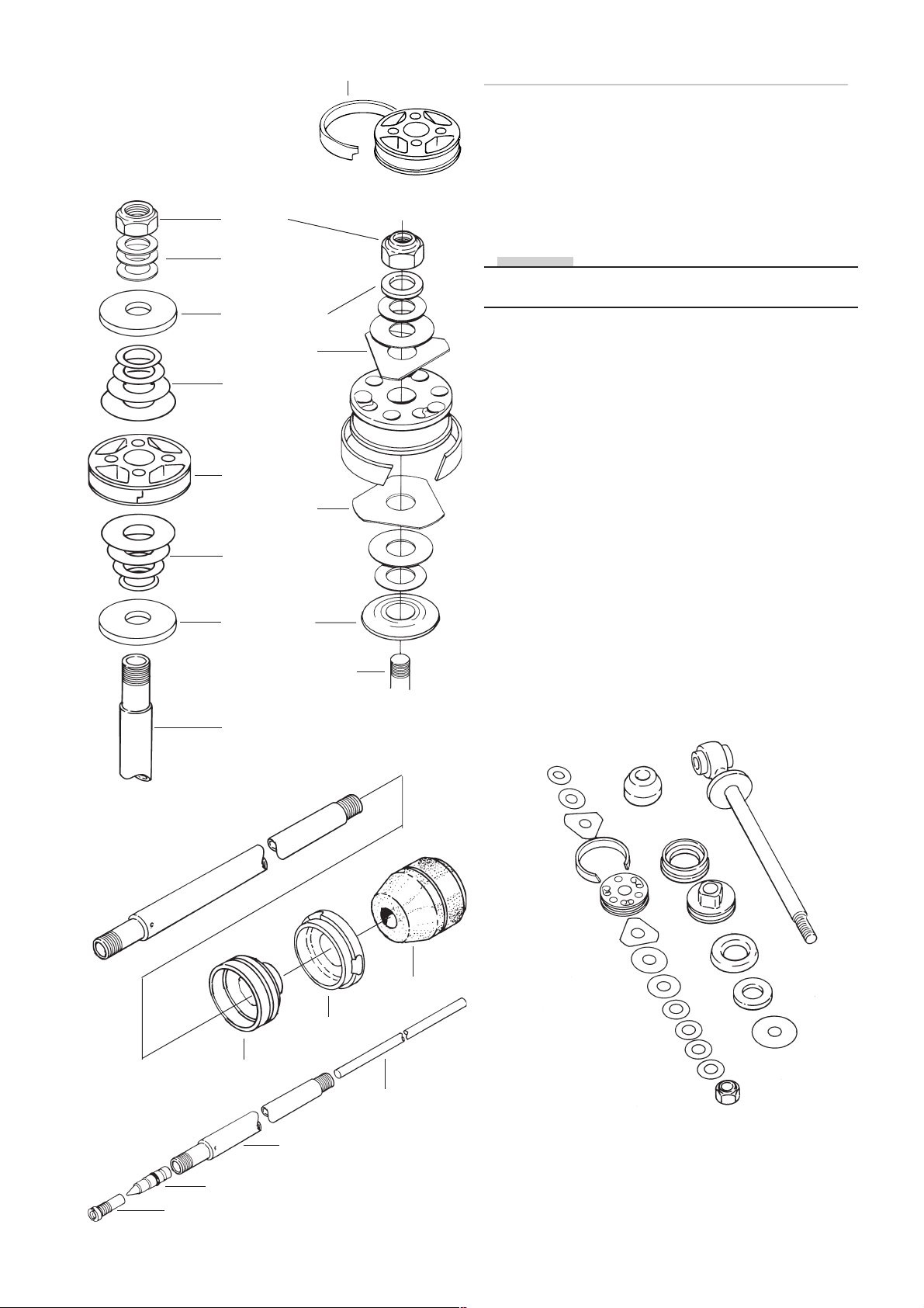
Piston band
Dismantling the piston shaft assembly
3:1
Fasten the shaft assembly in a vice with soft jaws. Use
clamping tool (727-xx)
3:2
Lock nut
Washer
Clamp washer
Triangle shim
Rebound
shims stack
Piston with
piston band
Triangle shim
Compression
shims stack
Stop washer
3:2
Remove the lock nut, the rebound shims stack, the
damper piston and the compression shim stack.
NOTE!
Put the shim stack aside and place the shims in the same
order as they were fitted on shaft.
3:3
Remove all the other parts from the shaft and put them
aside in correct order.
3:4.
Remove the end eye, use a heatgun.
Remove the adjustment valve jet, the adjustment needle
and the adjustment pin.
3:5
Clean all parts carefully and inspect for wear or damage.
Check the o-ring of the needle and replace if necessary.
3:6
Inspect the shaft for bends and scratches.
3:7
Replace piston ring, o-rings and lock nut.
3:5
Piston shaft 12 mm
Piston shaft 14 mm
Seal head
3:8
If necessary replace bump rubber, scraper ring and cap,
seal head assembly and eventual other defect parts.
3:3
Bump rubber
End cap
Piston shaft (12mm) and
components belonging to it.
Adjustment pin
3:6
Piston shaft
Needle
Valve jet
31
Page 32
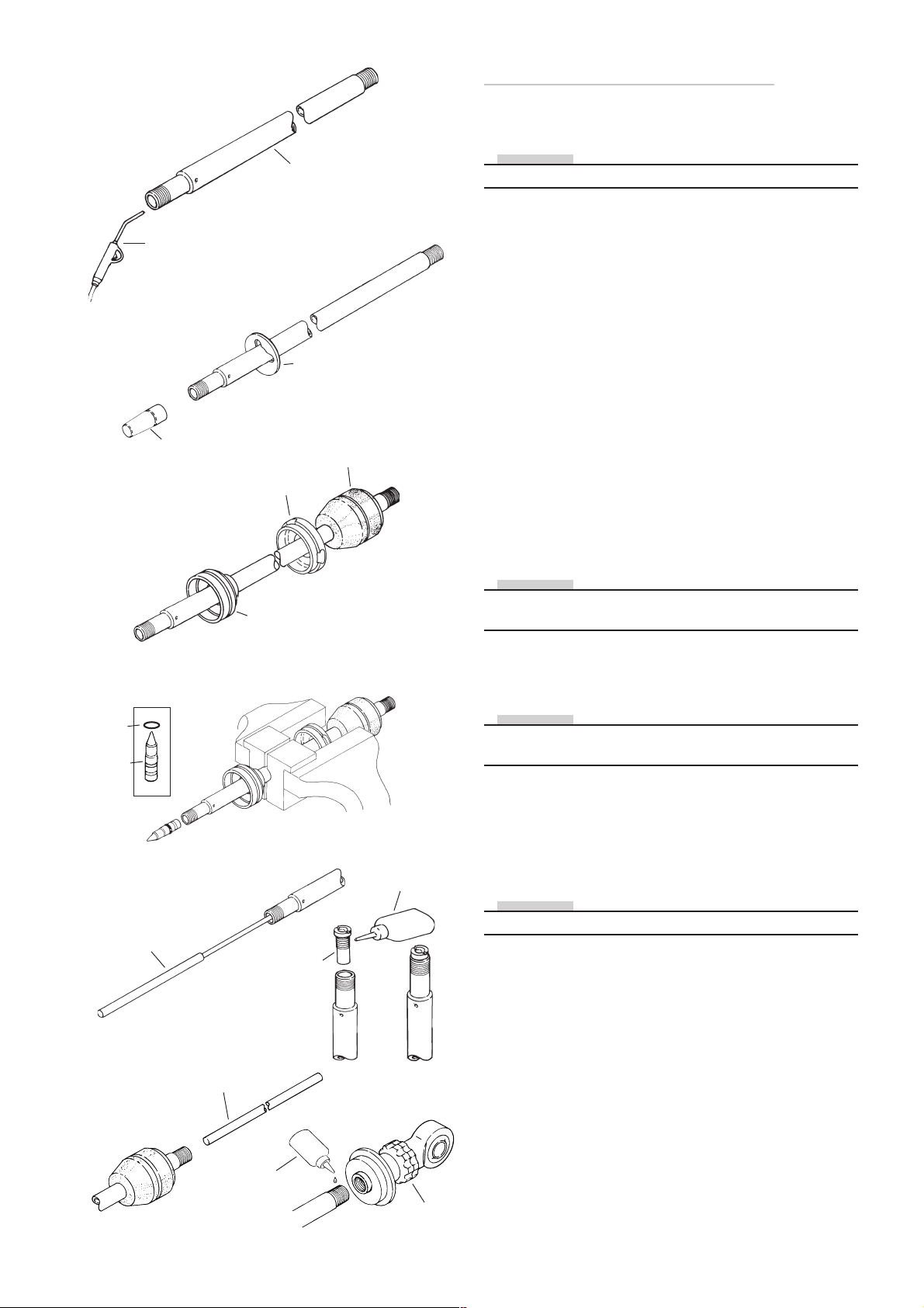
LOCTITE
4:3
4:1
Pressure
air gun
Fiting
sleeve
4:4
Piston shaft
End cap
Seal head
4:2
Spacer
Bumper
rubber
Reassembling the piston shaft
4:1
Blow the piston shaft clean with compressed air.
NOTE!
Apply Öhlins red grease (146-01) to all o-rings and seals.
4:2
Check the spec.card to see whether spacers are to be
used on the piston shaft. If so, mount these before fitting
the seal head assembly.
4:3
Use fitting sleeve (739-01) to protect the seal in the seal
head assembly.
Lubricate the piston shaft with shock absorber fluid so
that the seal head assembly slides on easily.
4:4
Put on the end cap and the bump rubber.
4:5 - 4:8 14 mm shaft only
4:5
Grip the piston shaft with soft jaws 727-xx.
Fit the O-ring on the adjustment needle. Apply plenty of
red grease on the O-ring so that the needle slides easily
into the piston shaft.
NOTE!
Always ensure that the correct needle is used in relation
to the nozzle.
O-ring
Needle
Tool 1738-01
4:8
4:6
Adjustment rod
4:5
Nozzle
4:9
Loctite 222
4:7
4:6
Press the needle down, using the tool 1748-01, until it
comes to a stop.
NOTE!
Check to see if the seating in the nozzle is chamfered, the
nozzle must be replaced with one without chamfer.
4:7
Carefully tighten the nozzle. Use Loctite 222.
4:8
Apply a little red grease to the adjustment rod and insert
it into the piston shaft from the top.
NOTE!
Ensure that the thread on the piston shaft is free from oil.
Mounting the end eye.
4:9
Use Loctite 270 on the piston shaft thread, screw the end
eye on and tighten using an adjustable wrench.
Tightening torque: See page xx, xx, xx
Loctite 270
End eye
32
Page 33
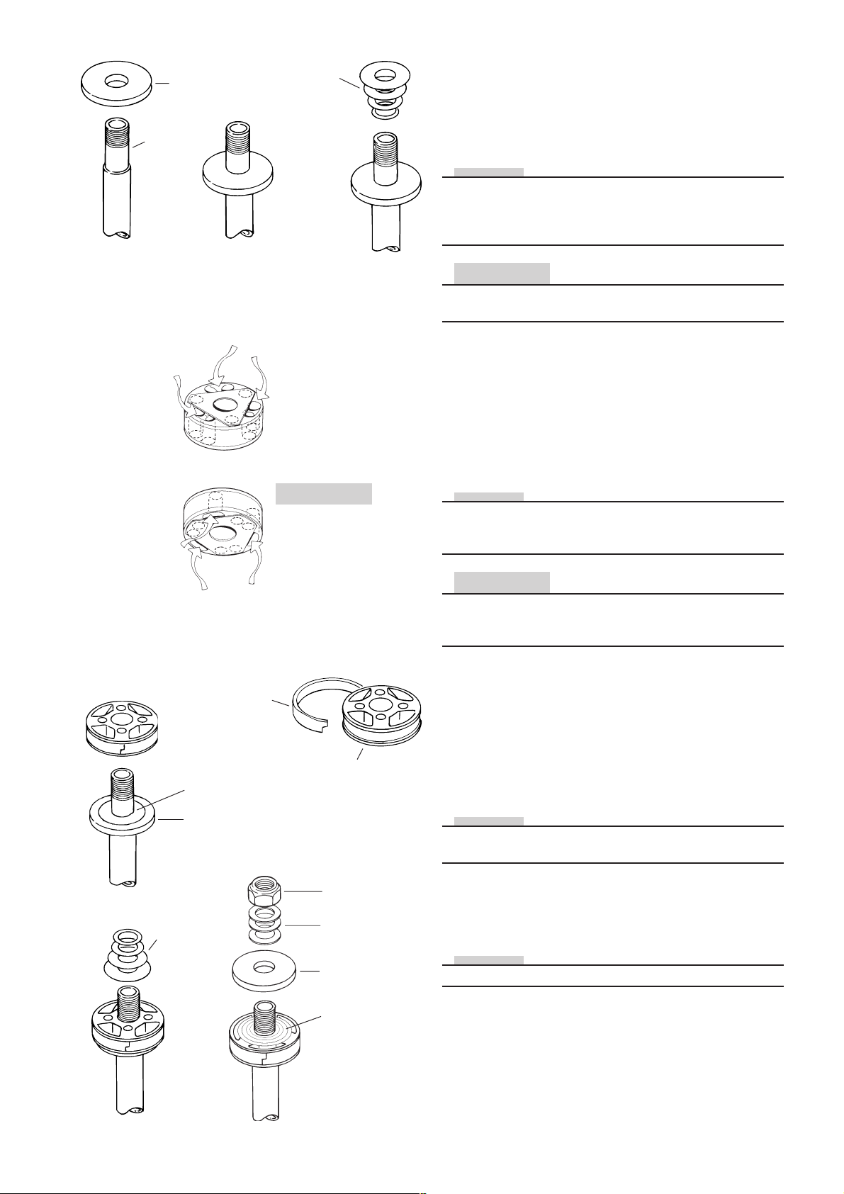
Stop washer
Piston
shaft
4:11
Compression
shims
4:13
Mounting of piston on piston shaft
and fitting shims
4:10
Grip the end eye in a vice. Use soft jaws.
Put the “top out” spring in position, if one is beeing used.
NOTE!
Always ensure that the correct spring is used. Check also
that the spring does not protrude too far above the sleeve.
There is a risk that the sleeve will slide down when tightening the shims nut.
CAUTION!
The chamfered side of the stop washer must face away
from the lock nut.
4:15
Teflon
band
Shims
Stop washer
4:13
Rebound shim
CAUTION!
Compression shim
4:17
4:11
Put the stop washer in position.
4:12
Check shims and replace if necessary.
4:13
Place shims on the compression side according to the
spec. card.
NOTE!
Make sure to put the shims in right order and that the
shims are in correct position to the piston. (See spec.
card)
CAUTION!
When a triangular shim (12mm shaft) are beeing used it is
of vital importance that they are in correct position according to illustration.
4:14
Ensure that the correct piston is beeing used. If a flat
piston is used face the piston using 1200 abrasive paper
to ensure a completely even and flat surface. Ensure that
there are no burrs or particels on the piston or in the fluid
ducts.
Piston
4:15
Put the piston on the piston shaft.
NOTE!
Ensure that the piston faces the correct way. The grooved
side of the piston must face the nut.
4:16
Rebound
shims
Lock nut
Washer
Clamp washer
Compression
shim stack
4:16
Fit the shims on the rebound side. Carefully check the
spec.card to see which clamp washer is to lie on the top
shim.
NOTE!
There are several different types of clamp washers.
4:17
Refit the washer and the lock nut. 14 mm shaft tighten to
30 Nm and 12 mm shaft to 20 Nm.
33
Page 34
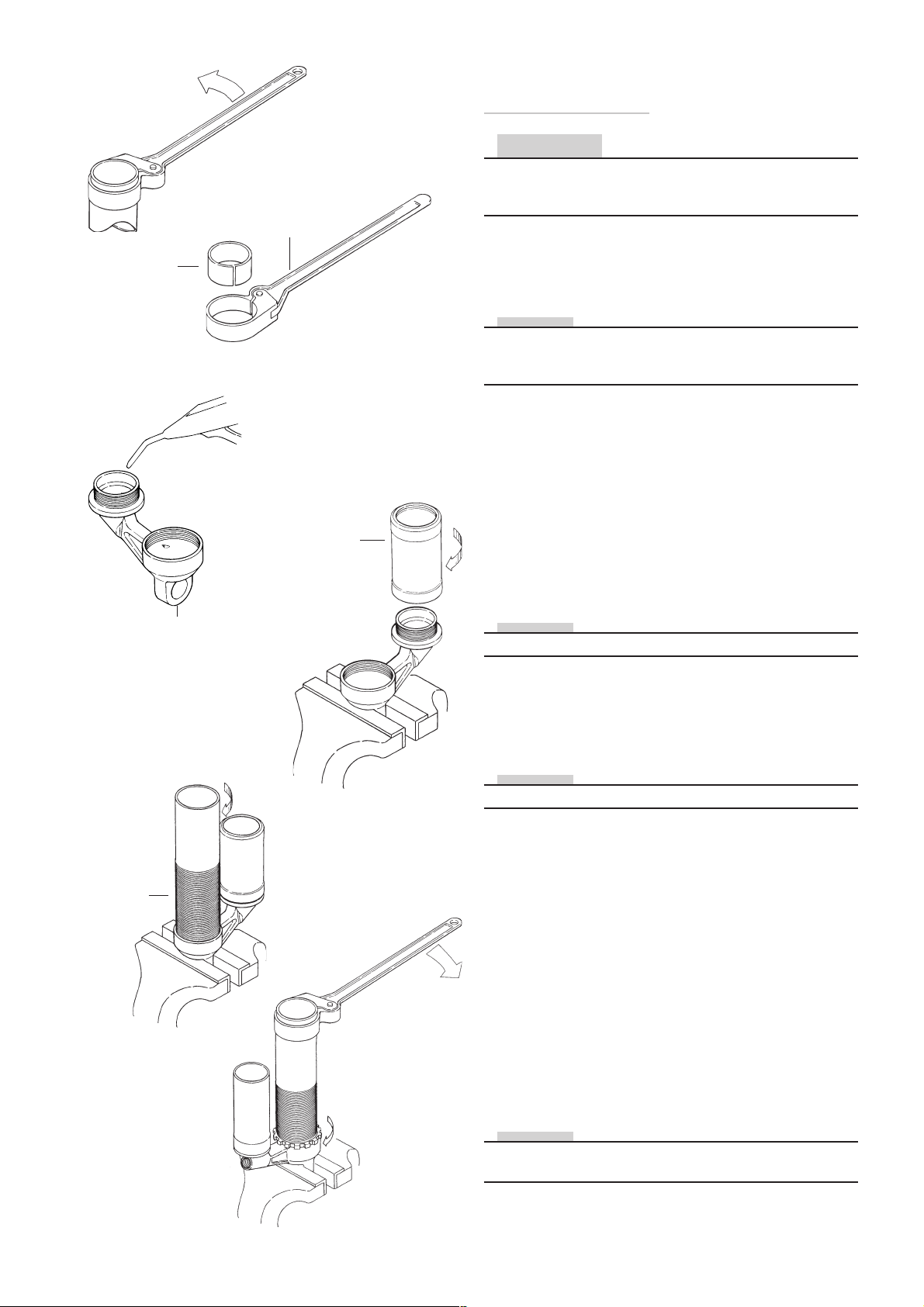
Sleeve
737-xx
Compressed air
5:1
Removing and refitting
the cylinder head
CAUTION!
Removing the cylinder head is only carried out on shock
absorbers with internal dividing piston or when the cylinder tube or reservoir tube must be changed.
Tool 738-01
5:1
Grip the shock absorber head in the vice with soft jaws.
Use tool (738-01) in combination with sleeve (737-xx) to
loosen the cylinder tube.
NOTE!
The cylinder head is fastened with Loctite. It is necessary
to heat the surfaces near the threads to remove the
cylinder tube and the reservoir tube.
5:2
Use tool (738-01) in combination with sleeve (737-xx) to
loosen the reservoir
Cylinder head
Shock
absorber
body/
Cylinder
tube
5:7
5:4
Reservoir
5:5
5:3
Screw cylinder tube and reservoir out by hand. Remove
and waste the O-rings from the cylinder head
5:4
Blow the shock absorber head clean with compressed
air. Ensure that there are no particles left in the ducts.
Apply red grease to new O-rings. Fit new O-rings.
NOTE!
Ensure that the correct O-rings are beeing used.
5:5
Grip the shock absorber head in the vice with soft jaws,
screw the gas reservoir in place by hand. Make certain
that the O-ring has not been damaged. Tighten the reservoir using tool 738-01 and sleeve (737-xx).
NOTE!
Tighten using moderate force, see drawing page.
5:6
A retainer ring is used on some cylinder tubes. Loctite is
not necessary if a retainer ring is used. Otherwise use
Loctite 542.
5:7
Screw the cylinder tube to the bottom and check that the
O-ring has not been damaged.
5:8
210 Nm
5:8
Tighten the cylinder tube using tool 738-01 and sleeve
737-01 insert tool 1798-01 in the cylinder tube to prevent
deformation when tightening. Torque tighten to 210 Nm.
If a lock nut is used, tighten it with tool 743-01.
5:9
Screw in the filler screw with the O-ring.
NOTE!
If a oil filling machine is beeing used, the O-ring and screw
are not to be fitted at this moment.
34
Page 35
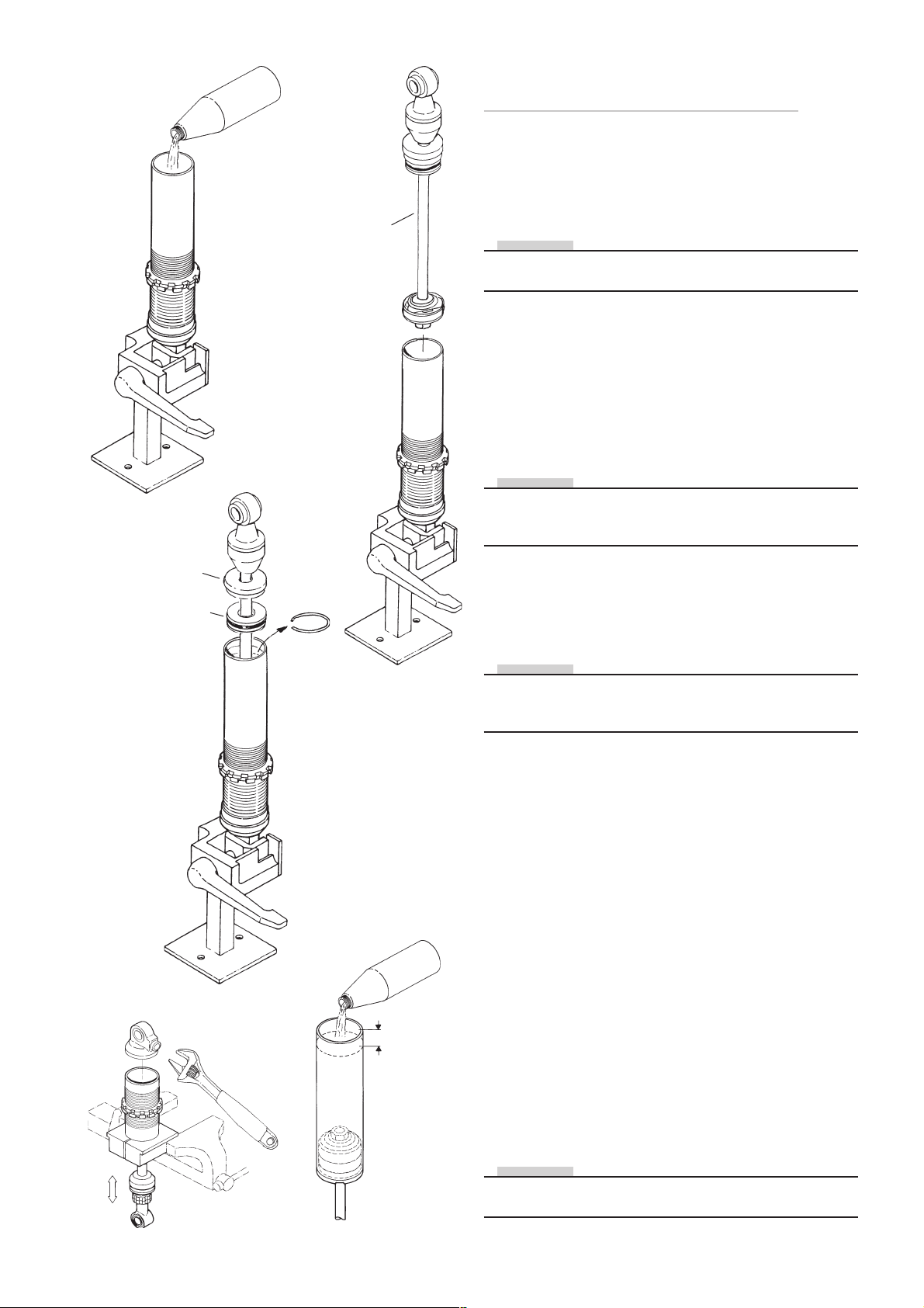
6:2
6:4
6:3
Piston shaft
assembly
Assembling
the shock absorber type E and D
Shock absorber emulsion type E only
6:1
Fasten the shock absorber in tool 773-01
NOTE!
Apply Öhlins red grease 146-01 to all o-rings and seals
and a thin layer to the inside of the cylinder tube.
6:2
Fill the cylinder tube with Öhlins oil to the recommended
oil level. See spec.card.
6:3
Make sure that the adjustment needle is fully open before
installing the piston shaft. Install the piston shaft assembly into the cylinder tube.
NOTE!
12 mm shock absorbers have two circlips. The lower circlip
must be fitted before the stop rubber and rthe seal head
are installed.
End cap
Seal head
6:7
Circlip
6:8
15 mm
6:4
Install the circlip and make sure it is properly seated before
the end cap is fixed by knocking it in with a plastic hammer.
NOTE!
Shock absorbers without dividing piston must be pressurised in upright position. I.e. the shock absorber head facing upwards.
Shock absorber
with internal dividing piston type D only
6:5
fasten in tool 791-01
6:6
Make sure that the needle is fully open before installing
the piston shaft. Install the piston shaft assembly into the
cylinder tube. Install the seal head, circlip and and make
sure it is properly seated before the end cap is fixed by
knocking it in with a plastic hammer.
6:7
Turn the cylinder tube so the piston shaft is facing downwards.
6:8
Fill the cylinder tube with Öhlins oil ( to approximately 15
mm from the top of the tube. Bleed out remaining air by
slowly moving the piston shaft up and down in the cylinder tube. Do not push hard, just move the the shaft slowly.
NOTE!
To obtain maximum oil volume, pull the shaft out to fully
extended length before installing the dividing piston
.
35
Page 36
Tool
720-02
6:10
6:8
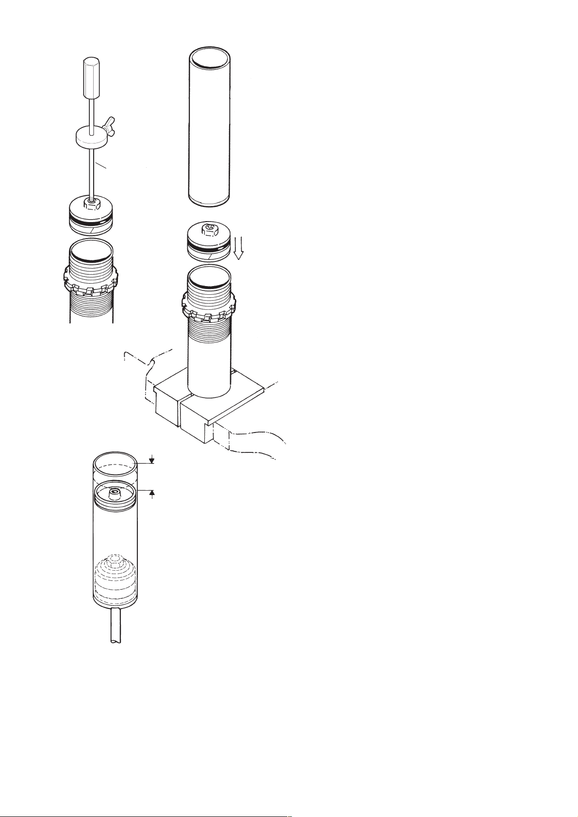
Inspect the dividing piston for wear or damage.
6:9
Replace o-rings and piston rings with new.
Use Öhlins grease 146-01 on all o-rings and seals.
6:10
Install the dividing piston into the cylinder tube and set the
piston position with 757-xx and a vernier or tool 720-02 to
set the dividing piston depth.
See spec. card for correct position and illustration.
6.11
Install the centre screw and use tool 757-xx to hold the
dividing piston when tightening the screw. Wipe off
eccesive oil.
6:12
Clean the cylinder tube thread with cleaner and use Loctite
542 or 270 on the thread when installing in the cylinder
head. Turn the tube body around and fasten the cylinder
head in a vice with clamping tool 791-01.
Use tools 737-xx and 738-01 to tighten the body tube.
See spec
card
36
Page 37
7:1
7:3
Lid
064-01
Dividing
piston in
bottom
position
7:2
Tool
720-02
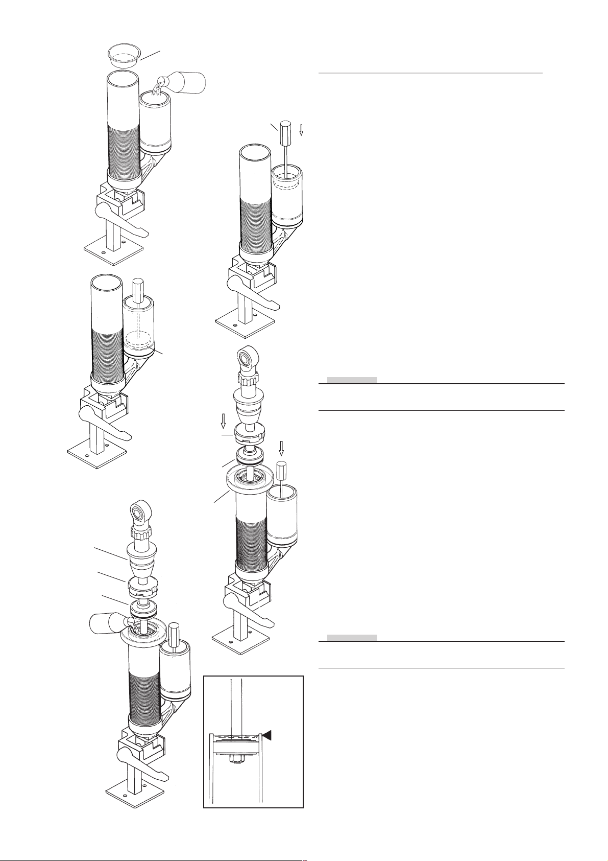
Assembling the shock absorber
with external reservoir type P and H
7:1
Insert a plastic lid (764-01) in the cylinder tube. Fill up
with Öhlins fluid all the way to the edge of the reservoir.
7:2
Push the dividing piston, with teflon band and O-ring fitted, down in to the reservoir without allowing it to be
pressed back over the circlip groove, make sure that there
is no air between the piston and the oil.
7:3
Push the dividing piston to the bottom, using tool 720-02.
Close the compression adjuster.
Measure the distance from the edge of the reservoir to
the upper edge of the dividing piston and make a note of
the lenght. Fill the cylinder tube with Öhlins fluid to about
10 mm below the circlip groove.
7:4
Install an fluid retainer cup. Insert the piston shaft into the
cylinder tube. Take care, that fluid does not squirt up.
When the piston is submerged in the fluid the piston shaft
should be pressed down hard, to force out air between
the shims and piston.
NOTE!
This labour forces fluid through the apertures of the main
piston and helps to bleed out all air.
Bump
rubber
End cap
Seal head
assembly
7:5
End cap
Seal head
assembly
Fluid
retainer
cup
7:4
7:5
Wait a while to allow air bubbles to rise to the surface.
Pull the piston shaft up a bit, without allowing the bleed
holes to come above the surface. Top up with more fluid
if required.
7:6
Repeat this procedure until all air is expelled. If the shims
are very hard, a check can be made by pushing down the
piston rod very hard. If there is still air remaining the fluid
level will move. If so, strike the end eye firmly with a plastic hammer to make the shims open.
7:7
When all air has been expelled, pull the piston shaft up as
far as possible without the bleed holes in the piston shaft
coming above the surface of the fluid. Top up with fluid
all the way up to the edge of the cylinder tube.
NOTE!
Rotate the piston shaft lightly to seat the teflon band properly against the body tube bore.
7:5
Fluid
level
37
Page 38
End cap
Seal head
assembly
8:1
8:3
Retainer
ring
8:4
8:2
7-10 mm
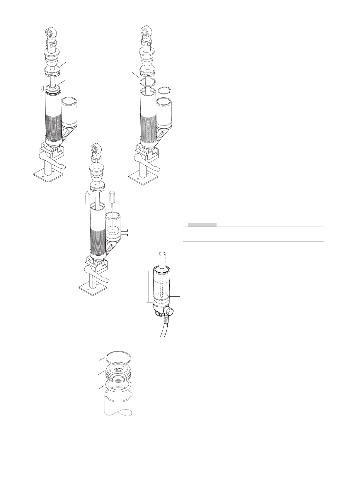
Mounting the seal head assembly and
end piece on reservoir
8:1
Push the seal head down against the fluid and carefully
down to the O-ring groove make sure that the bleedhole
is facing away from you. Then push the piston shaft down
halfway. Make sure that the dividing piston is fully down
to the bottom of the reservoir.
8:2
Open the compression valve and, using a blunt screwdriver, push the seal head assembly down until the circlip
groove is visible.
8:3
Fit the circlip and pull up the piston shaft up, make sure
that the circlip is fixed in its groove and in the seal head
assembly groove. Fit the end cap by tapping it in with a
plastic hammer.
8:4
With the piston shaft fully out measure again from the
edge of the reservoir to the upper edge of the dividing
piston. If the value between the first and the second
measurement is more than 7 mm or less than 4 mm, open
the filling screw and adjust the position of the dividing
piston carefully, if the piston is too far in top up with fluid
in filling hole. Then screw in the filling screw.
NOTE!
Put the dividing piston in correct position according to
table.
Circlip
End cap
O-ring
8:5
Reservoir Position
length (L) of dividing piston (D)
80 47
L
P
90 57
110 77
120 87
133 100
150 117
180 147
220 187
8:5
Fit the O-ring on the cap assy, with the aid of red grease
and push it into the chamber using tool 720-03. Fit the
circlip make certain that it enters its groove properly.
38
Page 39
8:6 - 8:7
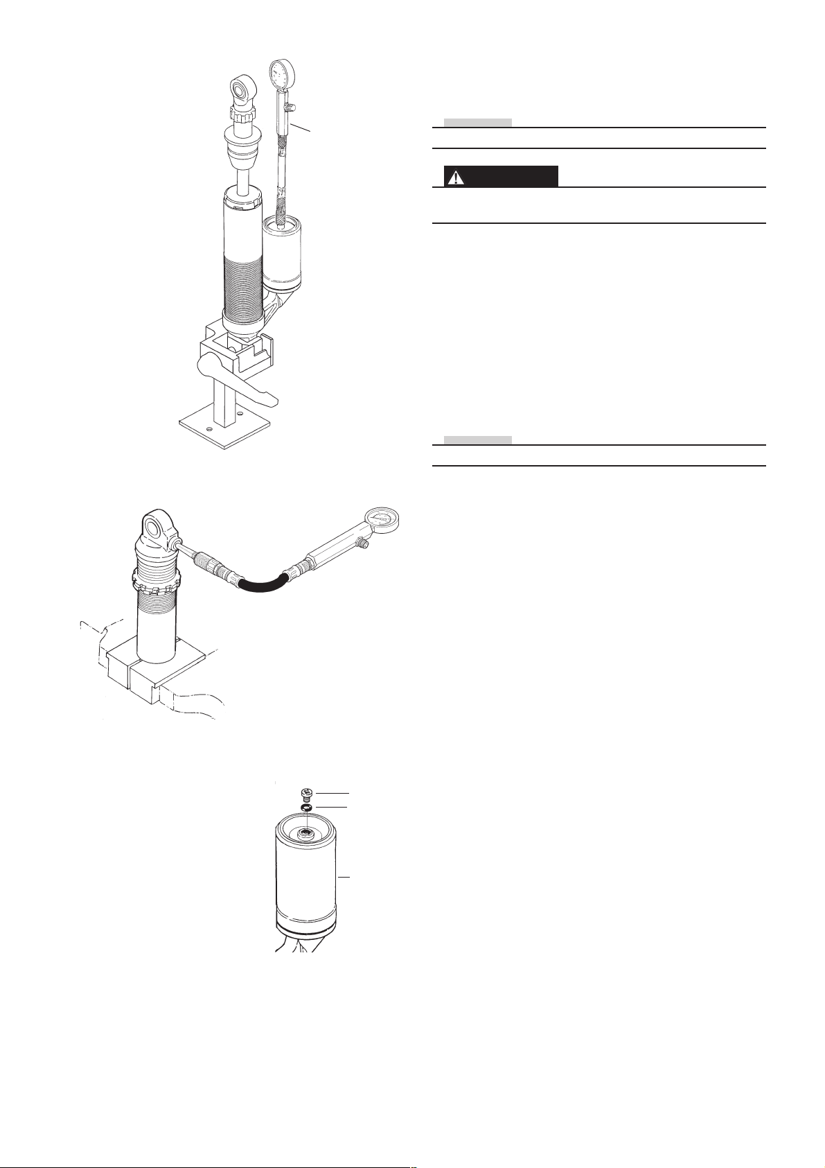
Pressurising and assembling protective
cover on the cylinder
Pressure gauge
1781-01
NOTE!
Nitrogen (N2) gas . Use pressure gauge (1781-01).
WARNING!
Use of inflammable gas for pressurising the shock
absorber can be hazardous. Use nitrogen gas (N2) only.
Tap the end cap into the cylinder tube gently with a plastic
hammer.
8:6
Check the gas pressure stipulated in the spec.card. Screw
out the gas filler screw and O-ring. Dip the needle of the
gas tool (1781-01) in red grease and insert the needle
through the gas filler valve.
8:7
Charge with gas to the correct pressure, according to the
spec.card.
NOTE!
Ensure that there is no leakage of gas or fluid.
8:8
Screw in the gas filler screw with O-ring.
8:6 - 8:7
8:8
Screw
O-ring
Reservoir
39
Page 40
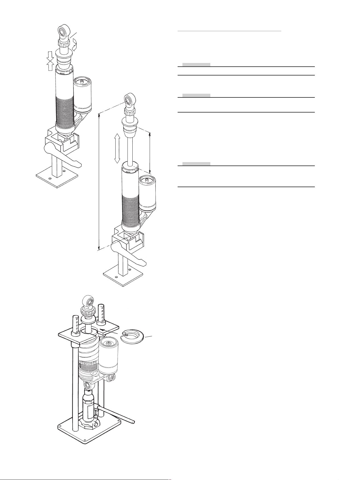
Rebound
adjuster
9:1
9:2
Stroke
Settings and spring assembly
9:1
Push the piston shaft down to its bottom position and
close the rebound adjustment fully.
NOTE!
Use your fingers only. No tools may be used.
If everything is correct, the piston shaft should stay down.
NOTE!
Certain shock absorbers are provided with an integrated
“bleed”, causing the piston shaft to move up slowly.
Open the adjustment the number of clicks stated in the
spec.card.
9:2
Measure the length, stroke and compare to spec.card.
Check the free length of the spring.
NOTE!
Shock absorbers with top-out spring will be 3 - 4 mm
shorter than specified length on the spec.card, before the
main spring is fitted.
Length
9:3
Mount the spring and spring-clip and adjust the pre-load
rings according to the spec. card.
9:4
Measure the overall length and check it against the
spec.card.
9:3
Spring clip
40
Page 41

General
Contents
General .................................................................... 43
Honing ...................................................................... 44
Seal head .................................................................. 45
Compression adjuster ............................................... 47
Needle and housing .................................................. 47
Dismantling hydraulic spring pre-load ....................... 48
Assembling hydraulic spring pre-load ....................... 49
Hose ......................................................................... 50
End eye .................................................................... 51
Svivel, spacers .......................................................... 52
Oil and grease ........................................................... 53
Disposal of shock absorber ...................................... 53
Drawings ................................................................. 55
41
Page 42
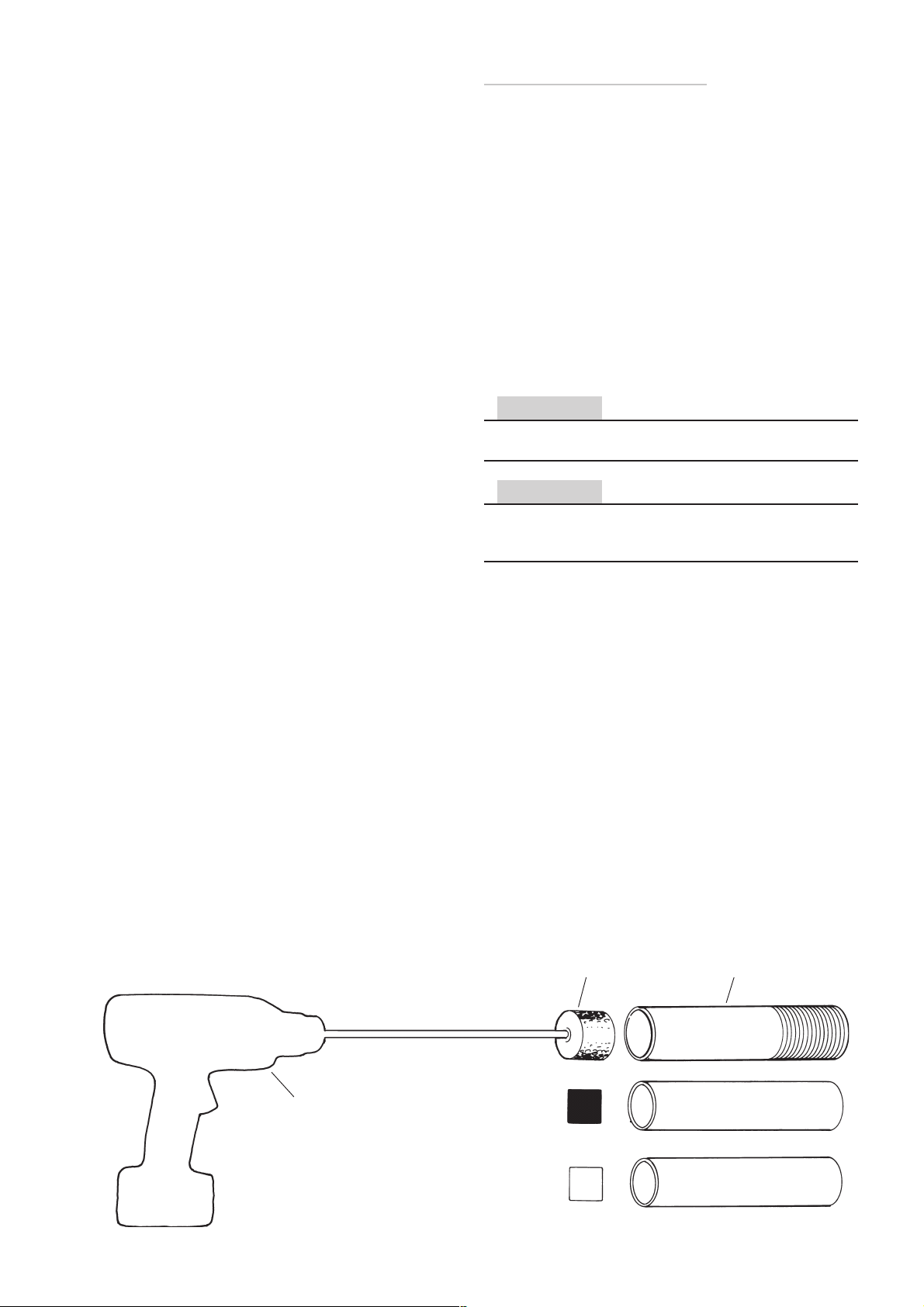
Honing of cylinder bore
1:1
Hone the cylinder tube and the gas reservoir.
1:2
Use black/grey honing brush (01726- 01, 01727- 01,
01728- 01, 01741- 01) for steel tube and white brush
(01727- 02, 01727- 03, 01728- 02, 01728- 03), for
aluminium tube.
1:3
Remove burrs from end of cylinder tube by using a file, or
replace it.
1:4
Clean the tubes very careful, use a degreasing detergent
and blow dry with compressed air.
CAUTION!
After honing, the tubes must be throughly cleaned, to avoid
damages from remaining metal particles.
CAUTION!
When a brand new tube is installed it is necessary to
hone it, as this is normally not a step in the manufacturing
process.
1:1
Drill
Honing brush Cylinder tube
Steel
1:2
Aluminium
42
Page 43
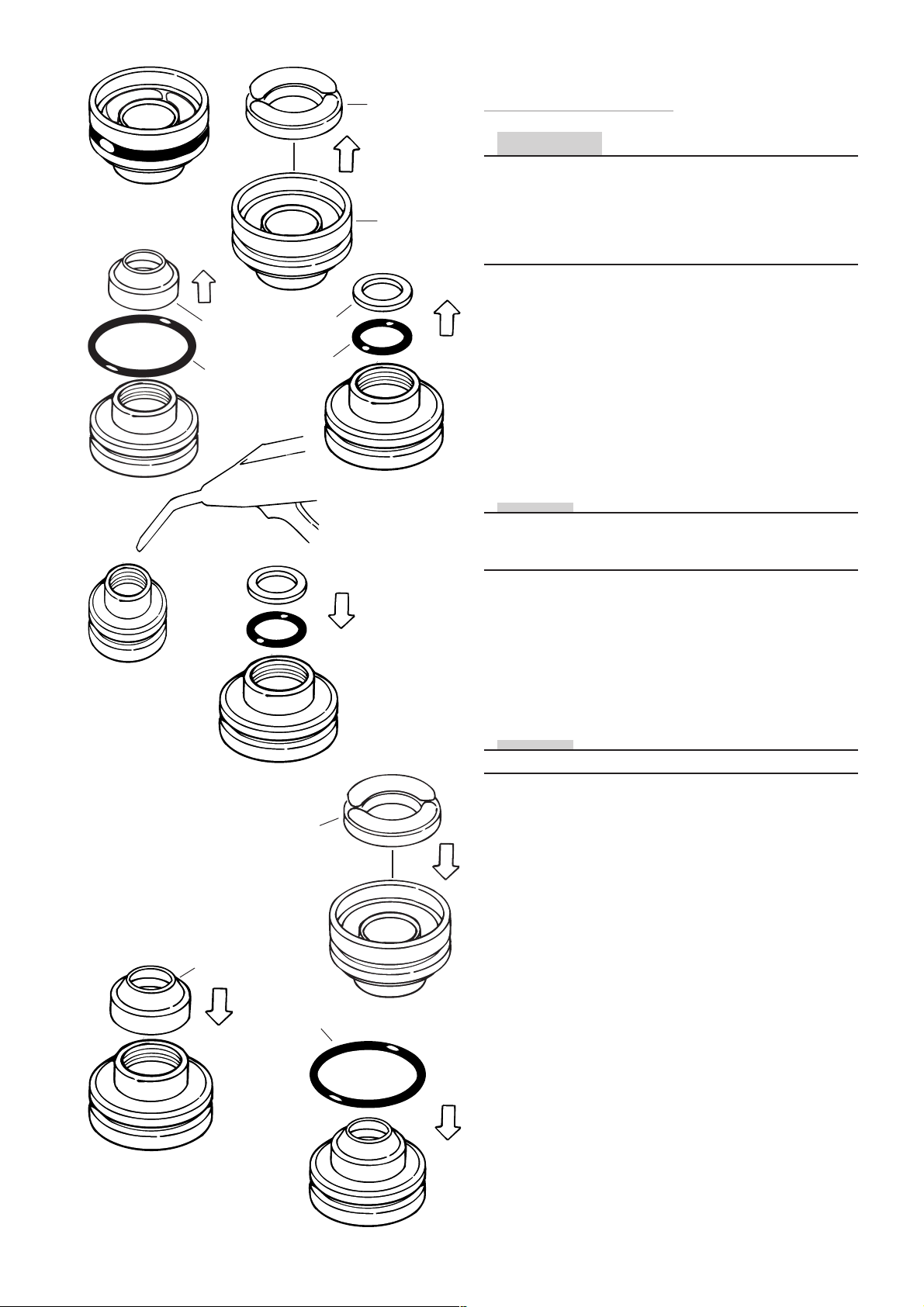
Ready-assembled
seal head
2:5
Scraper
ring
Outer
o-ring
2:2
Support
ring
X-ring
2:6
Stop rubber
2:1
Seal head
2:3
Dismantling and assembling
seal head assembly
CAUTION!
The seal head should if possible be mounted as a readyassembled piece The x-ring, the support ring, the scraper
ring and the outer o-ring can be changed, however this is
a very difficult procedure and should be avoided if not
absolutely necessary. Seal head for 12 mm shaft available
only as assembled part.
2:1
Lift the internal stop rubber out
2:2
Remove the outer o-ring and the scraper ring
2:3
Remove the support ring and the x-ring.
2:4
Clean the seal head.
NOTE!
It is not possible to remove the bushing. If the bushing is
damages a brand new ready-assembled seal head should
be mounted.
2:5
Blow clean with compressed air where the x-ring is to be
fitted. Ensure that there are no foreign particles left inside.
Scraper
2:8
Stop
rubber
2:7
Outer o-ring
2:9
2:6
First fit the support ring in place, then the x- ring. The x-ring
shall be nearest to the bushing.
NOTE!
Take care not to twist the x-ring when fitting.
2:7
Press the stop rubber into place.
2:8
Press on the scraper ring. Pack with white grease (0147-
01) in the space between scraper ring and the seal head
assembly.
2:9
Fit the outer O-ring with the aid of red grease.
43
Page 44
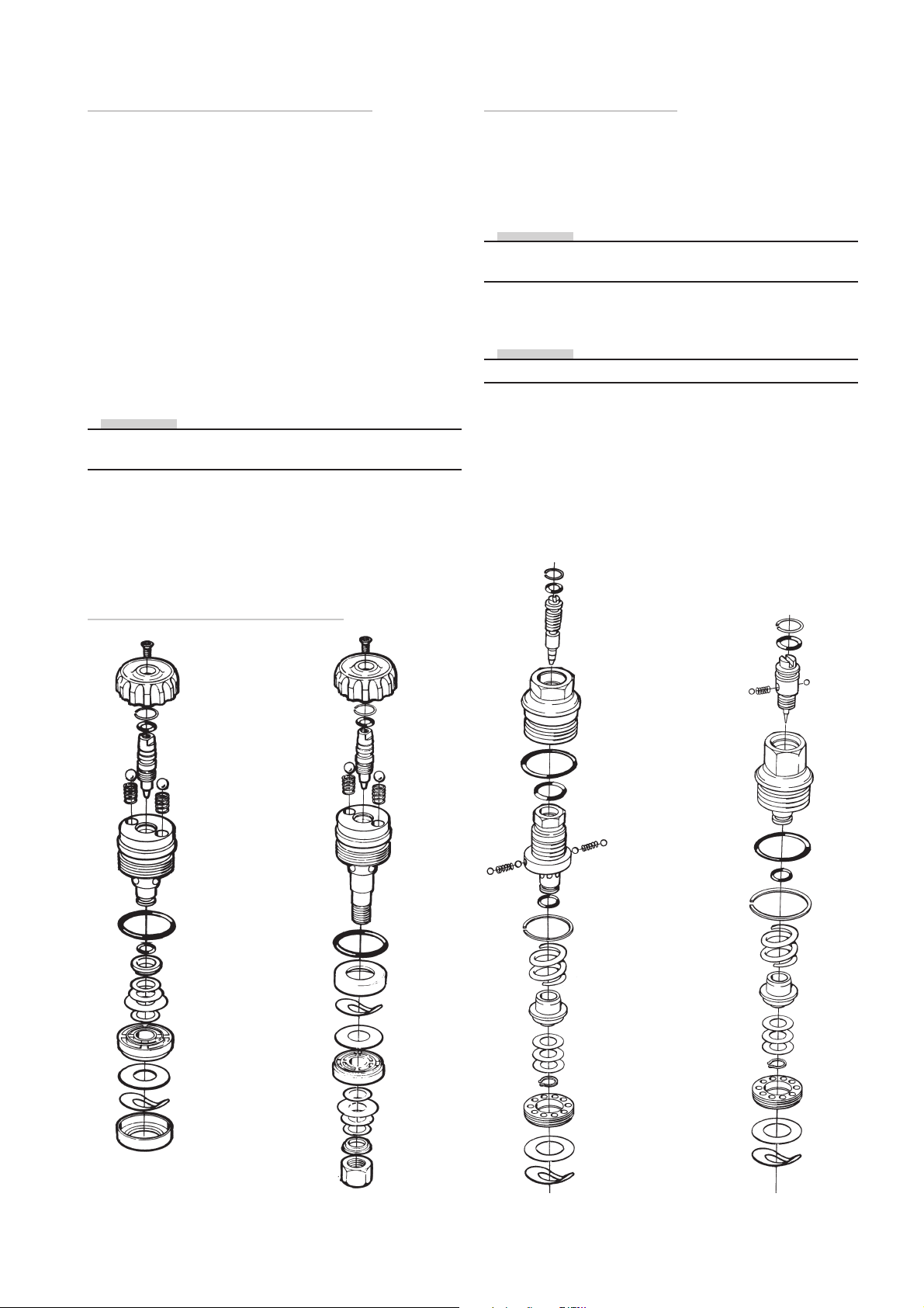
Dismantling and assembling
the compression adjuster unit
Assembling the compression adjuster
needle and housing.
3:1
Remove the screw of the adjustment wheel and remove
the wheel if fitted.
3:2
Loosen the adjuster with a 17 mm key. Remove the
adjuster from the reservoir and clean them exterally.
3:3
Clean the reservoir carefully. Inspect reservoir hose for
leaks or damages.
3:4
Disassembly the adjusters. Remove the outer O-ring, remove the circlip and screw the needle out.
NOTE!
Be careful not to lose the small steel balls and/or the spring
inside the needle.
3:5
Dissassemble the compression valve and the check valve
3:6
Inspect for damages and replace eventual damaged parts.
4:1
Blow the parts clean with compressed air.
4:2
Grease O-rings and end pieces. Red grease (0146-01).
NOTE!
Check to see if the seating in the nozzle is chamfered. If it
is, the nozzle must be replaced.
4:3
Fit the O-ring on needle.
NOTE!
Always ensure that the correct needle is beeing used.
4:4
Insert the ball 1, spring and ball 2, in that order, and then
insert the whole needle with balls and spring into the end
piece.
4:5
Turn the needle to the bottom position and feel that the
click positions are distinct.
Öhlins compression valves
Bob - compression valve
2-way compression valve
Hose connected reservoirPiggyback reservoir
MC R&T
Car
MX-Enduro
44
Page 45
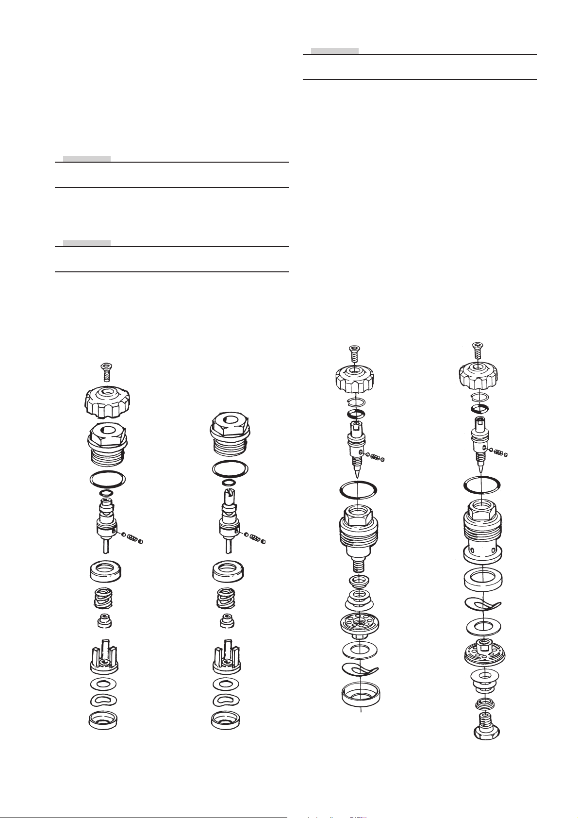
4:6
Blow with your mouth into the bleed hole to check that it
is closed.
NOTE!
Ensure that there is no chamfer on the clamp washer. If
there is, it must be replaced.
4:7
Fit the circlip. Fit the outer O-ring (338- 27).
Assemble the compression valve.
Always check the spec.card to see which compression
valve is to be used. If a pre-loaded valve is used, the preload depth must be calibrated.
NOTE!
All valves are to be faced using 1200 abrasive paper to
ensure a completely even and flat surface.
4:8
Assemble the compression valve and check valve. Put
the wave washer and then the shim in position.
NOTE!
The wave washer is to be fitted with the convex side facing the shim.
4:9
Carefully press these together. Carefully check with a pin
that the non return valve moves easily.
Compression valve
4:10
Fit shims according to the spec.card. Fit and tighten the
threaded end of the nozzle at 5 Nm.
Mounting the compression adjuster in
cylinder head/ reservoir top
4:12
Apply a little red grease where the compression valve is to
fit in the shock absorber head.
4:13
Put the valve in position and tighten using moderate force.
Piggyback 18 Nm, hose damper 15 Nm.
Refit adjustment wheel and screw. Open the compression
valve fully by turning the adjustment wheel anticlockwise.
Early model compression valve
Snowmobile
Piggyback reservoir Hose connected reservoir
45
Page 46
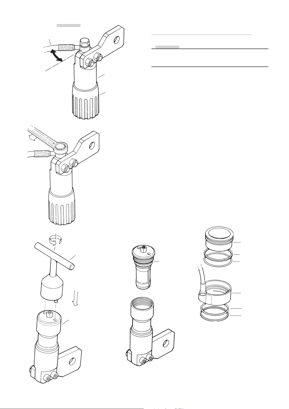
Hydraulic hose
NOTE!
Dismantling
hydraulic spring pre-load adjuster
NOTE!
Before taking off the spring pre-load adjuster from the
shock absorber, make a note of the hydraulic hose angle
on releation to the adjuster.
5:1
Adjuster cylinder
Adjuster knob
5:1
Remove the hydraulic hose from the adjuster cylinder and
drain oil.
5:2
Remove the adjuster knob and fasten the cylinder in a
vice with soft jaws.
5:3
Remove the end cap, use tool 1754-01.
5:4
Remove the shaft assembly, use a suitable drift to pree it
out from the piston side.
Remove all o-rings and replace them with new ones.
5:5
Remove the inner sleeve from the outer housing.
Remove and replace the two white guiding rings and all
o-rings with new ones.
Clean all parts thoroughly.
5:3
Tool 1754-01
End cap
5:4
Shaft
assembly
5:5
Inner sleeve
Guiding ring
O-ring
Outer
housing
O-ring
Guiding ring
46
Page 47
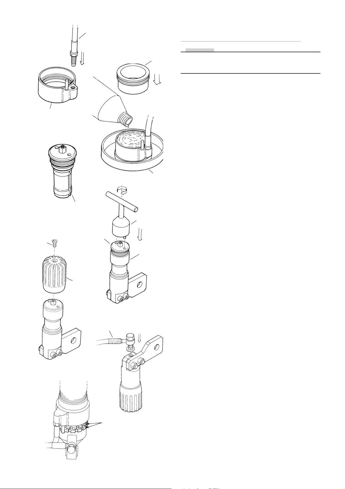
6:1
Hydraulic hose
6:3
Inner sleeve
Assembling
hydraulic spring pre-load adjuster
NOTE!
Use Öhlins shock oil, 105-01 in the hydraulic adjuster.
Use Öhlins red grease, 146-01 on all o-rings during
assembling.
6:1
Fit the hydraulic hose on to the outer housing.
Tightening torque 30 Nm.
Outer housing
6:4
Screw
Piston shaft
assembly
Piston shaft
assembly
6:6
Adjuster
knob
6:2
Hydraulic
hose
Tool
178-01
6:5
Tool 754-01
Adjuster
cylinder
6:7
6:2
Fit the outer housing on tool 1786-01 and fill oil up to the
top of the housing.
6:3
Install the inner sleeve into the outer housing.
Push the inner sleeve all way down to the bottom of the
outer housing.
The air will bleed out through the hydraulic housing.
6:4
Use Öhlins red grease 146-01 on the adjustment screw,
the o-rings and the bearing.
Assemble all the parts to one unit (the adjustment screw,
the piston, the bearing and all the o-rings).
6:5
Install the piston shaft assembly into the adjusting cylinder.
Make sure it is the right position for the guiding sleeve.
Tighten the cylinder end cap with tool 754-01.
6:6
Do not force the adjustment knob in to position, just put
it gently in place and tighten it with the centre screw.
Tightening torque: 1.5 Nm.
Use loctite 242 on the centre screw to secure it.
6:7
Turn the adjuster knob anti-clockwise until the piston stops
in its bottom position (maximum oil contents).
Fill up the adjustment cylinder with oil and screw the
two components (the adjustment cylinder and the outer
housing) together with the banjo bolt.
Tightening torque: 8 Nm.
Make sure there is no air left, check by opening the small
hexagon screw on the adjuster cylinder body.
Fill up with oil if necessary and tighten the screw.
6:8
6:8
Fit the compltete hydraulic adjuster on the shock absorber.
Make sure that the guide pin is in the correct position on
the two lock nuts on the body tube.
Fit the spring and set the initial spring pre-load.
Lock nuts
47
Page 48
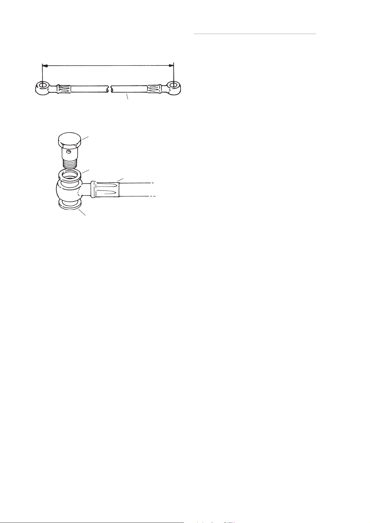
Length
7:5
Removing and refitting the hose
7:1
Check and note or mark witch side of the banjo nipple
that is turned against the cylinder head respectively the
reservoir head.
7:2
Note or mark the angles that the banjo connections have
in relation to the shock absorber and the reservoir.
Hydraulic hose
7:3
Loosen the banjo connections and remove the hose.
7:7
Banjo bolt
Sealing ring
Sealing ring
Banjo connection
7:4
Check the hose and the connections for damages.
Change parts if necessary.
7:5
Ensure that the hose has the correct length.
7:6
Use compressed air to blow the inside of the hose clean
before fitting.
7:7
Use new sealing rings to the banjo connections and refit
the connections exately as they were fitted before disassembling.
7:8
Torque tighten the banjo connections as recommended
for the respective screw dimensions.
7:9
See separate instructions and assembly codes (page xx).
48
Page 49
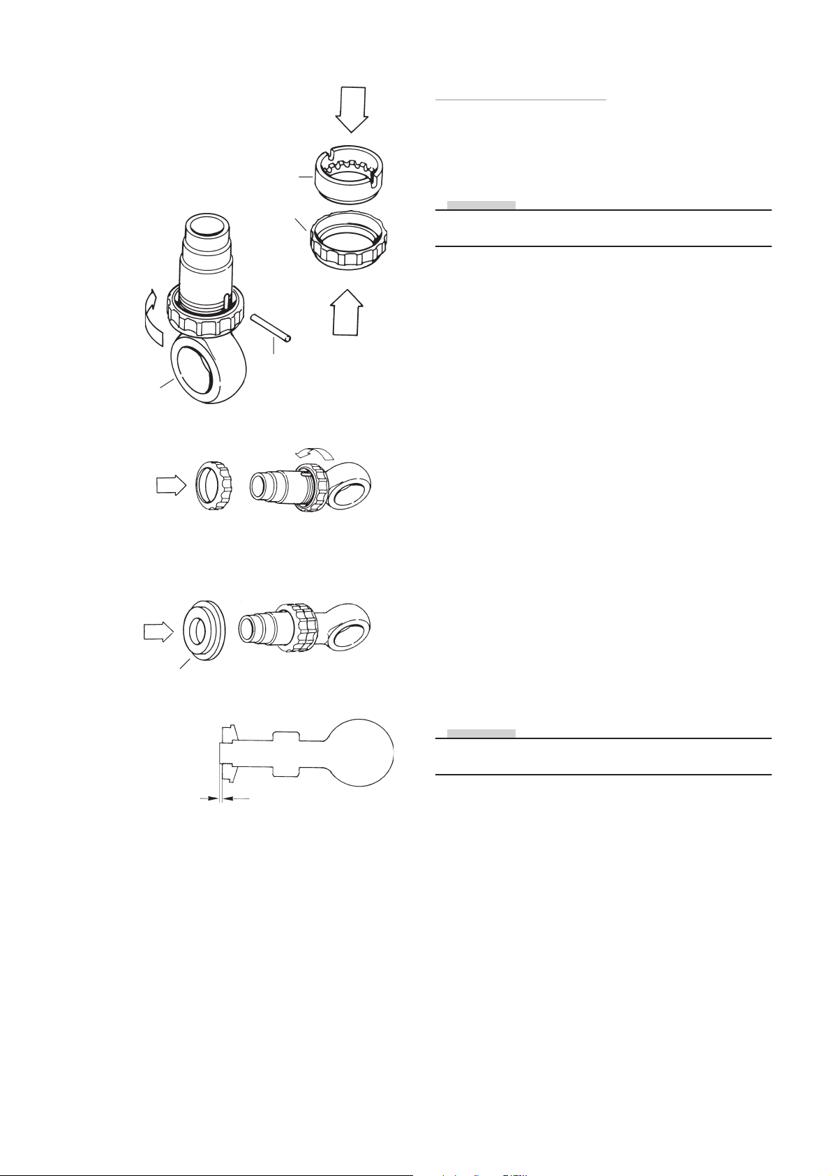
8:1
Dismantling and assembling
the end eye bracket
Dismantling
8:2
End eye
bracket
Adjusting wheel
Adjusting
wheel half
Cross pin
8:5
8:8
8:1
Fasten the end eye in a vice with soft jaws.
NOTE!
On some models the stop washer is pressed off the end
eye before the piston shaft is removed.
8:2
Pull the adjustment wheel upper half off.
8:3
Turn the lower adjustment wheel half downwards. Raise
the cross pin and remove it.
8:4
Remove the lower wheel half from the end eye.
Assembling
8:5
Press together the adjustment wheel in the closed half of
the adjustment knob. Use a vice with soft jaws.
8:6
Grease the thread on the end eye. Screw in the adjustment
wheel on the end piece so that the adjustment pin can be
fitted in its hole.
8:7
Screw the adjustment wheel maximum against the
adjustment pin. Press on the other half of the adjustment
knob with the aid of a sleeve 723-xx in a vice.
Stop washer
8:9
0,5 mm
Then screw down the adjustment wheel about 5-6 turns
so that the adjustment shaft is not damaged when fitting
the end piece on the piston shaft.
NOTE!
On some models the stop washer is pressed into position after the end eye has been fitted on the piston shaft.
8:8
Press the stop washer on the end eye using sleeve 723-xx.
8:9
Make certain that the stop washer bottoms properly. The
end piece should protrude about 0.5 mm above the washer.
8:10
Then mount the swivel bearing. Use Loctite 601 and drift
(721- xx). Press it in with the help of a vice. Measure to
ensure that the bearing is centered.
49
Page 50
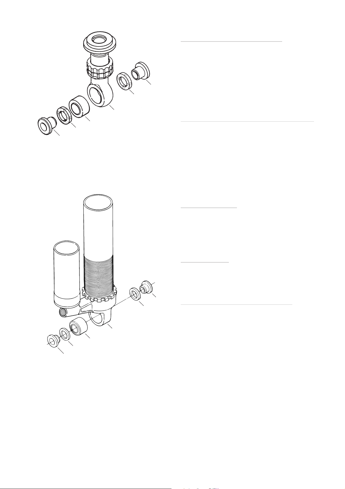
Spacer
9:1
Seal ring
End eye
Swivel bearing
Seal ring
Spacer
Dismantling
swivel bearings and spacers
9:1
Remove the spacers with a hammer and a drift. Remove
the seal rings.
9:2
Press the swivel bearing out. Use tools (721-xx) and (723xx).
Mounting swivel bearing and spacers
10:1
Apply loctite 601 if the bearing is fitted without circlips.
Press the swivel bearing into position. Use tool (721-xx).
10:2
Apply a little red grease 0146-01 or airfilter oil on the seal
rings. Place the seal rings in position and press in the
spacers Ensure that size of the spacers conforms to the
spec.card.
9:2
Spacer
Seal ring
Cylinder head
Swivel bearing
Seal ring
Spacer
Final inspection
11:1
Make a final visual inspection of the assembled shock
absorber. Ensure that there is no leakage and that all
surfaces are clean and undamaged.
Fitting decals
12:1
See separate instructions and fitting codes.
Tightening torque and greasing
13:1
See separate instructions.
50
Page 51

Information Öhlins Oil and Grease
Part No. Description Type/remarks Quantity
00105-01 Öhlins shock absorber fluid No 131 In shock absorbers 1 Litre
00105-10 Öhlins shock absorber fluid No 131 In shock absorbers 10 Litre
01306-01 Öhlins shock absorber fluid No 309 In shock absorbers and MX & Enduro steering damper 1 Litre
01306-10 Öhlins shock absorber fluid No 309 In shock absorbers and MX & Enduro steering damper 1 Litre
01305-01 Öhlins front fork fluid No 5 In cartridge type of front forks and Street steering dampers 1 Litre
01305-10 Öhlins front fork fluid No 5 In cartridge type of front forks and Street steering dampers 10 Litre
01310-01 Öhlins front fork fluid No 10 In cartridge and conventional type of front forks 1 Litre
01315-01 Öhlins front fork fluid No 15 In conventional type of front forks 1 Litre
01309-01 Öhlins front fork fluid In 43 mm R&T front forks 1 Litre
00146-01 Öhlins red grease Multi purpose grease 100 g
00146-02 Öhlins red grease Multi purpose grease 400 g
00147-01 Öhlins white grease When overhauling shock absorbers 100 g
00147-02 Öhlins white grease When overhauling shock absorbers 500 g
Disposal of Shock absorbers
The most efficient way to scrap a shock absorber is to
leave it to a metal waste treatment company. They have
resources for separating oil, plastic and different metals.
If you intend to do it yourself, follow the instructions for
disassembling of the shock absorber.
• The pressurized gas is N2 (Nitrogen) and can be re
leased into the air (air composed of 78% nitrogen).
• The oil must be poured out into a separate vessel and
handed over for destruction.
• Rubber and plastic details should be removed.
• The metal parts should be separated into two fractions;
aluminum and steel
Hand over the separated components to a waste treatment operator for further treatment and recycling.
51
Page 52

Drawings
Contents
Drawings ................................................................. 55
Grease instruction, singel .......................................... 56
Tightening torques, singel ......................................... 56
Grease instruction, twin ............................................ 57
Tightening torques, twin ............................................ 57
Greasing, twin adjustable .......................................... 58
Torques, twin adjustable ........................................... 58
Sticker location code ................................................ 59
Hose, TT44 mounting code ....................................... 59
52
Page 53
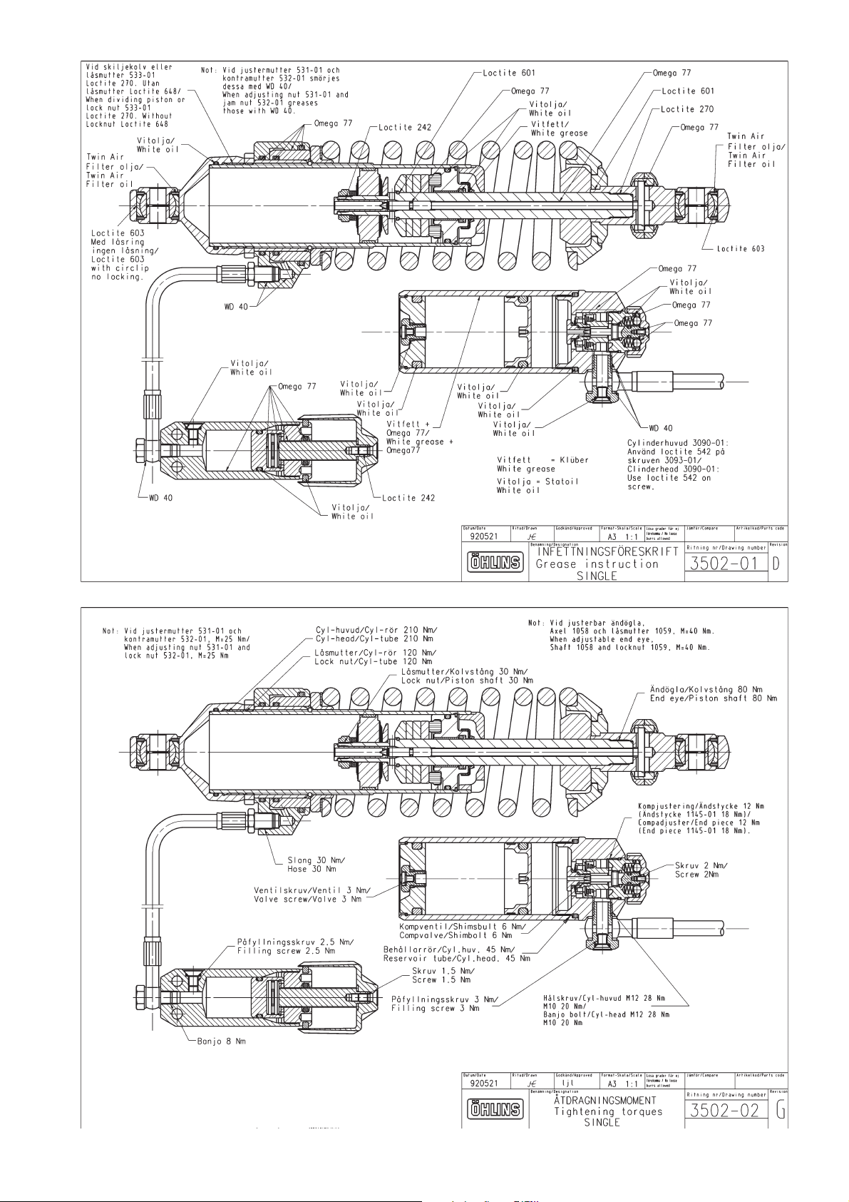
535455565758596061
Page 54
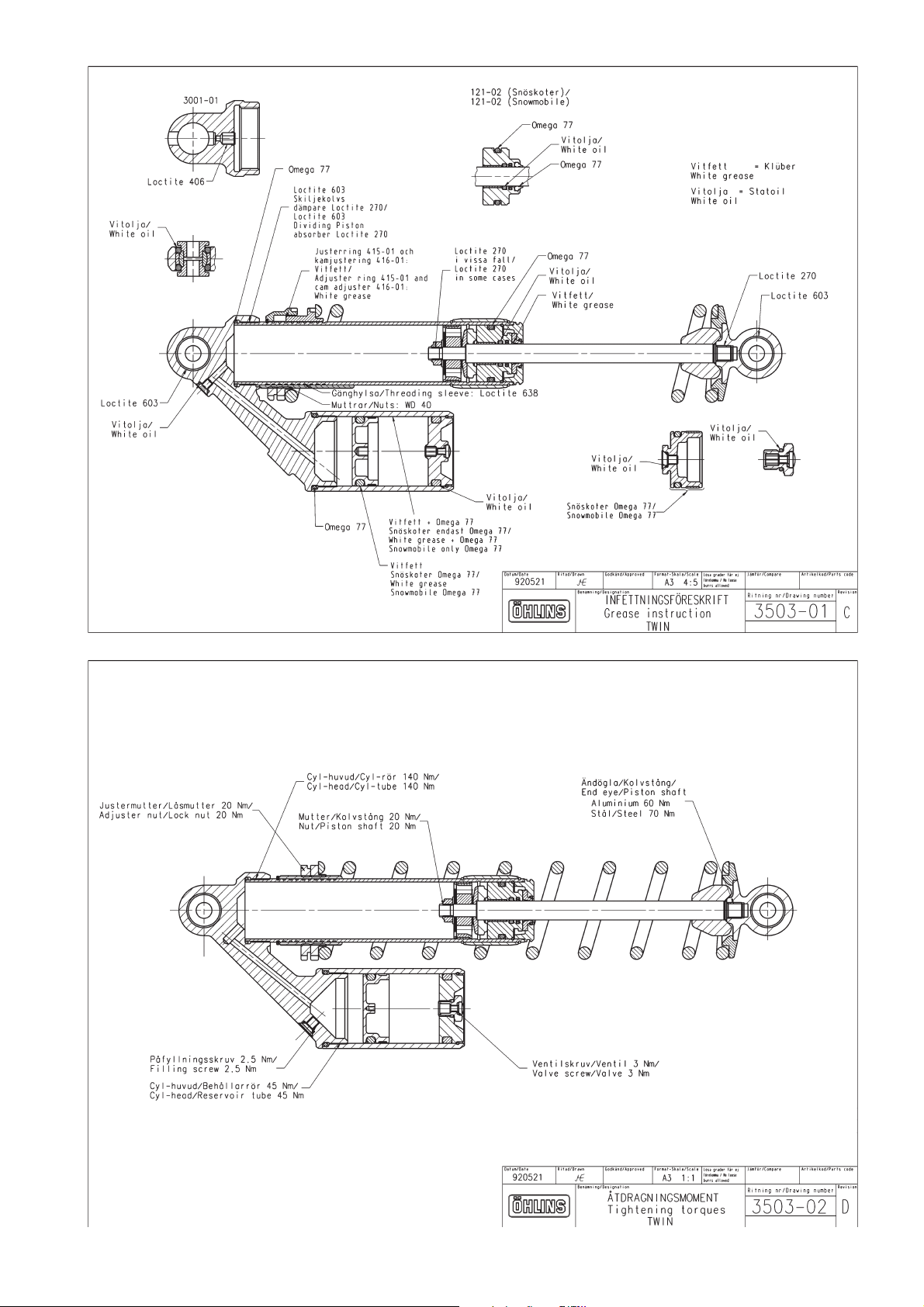
Page 55
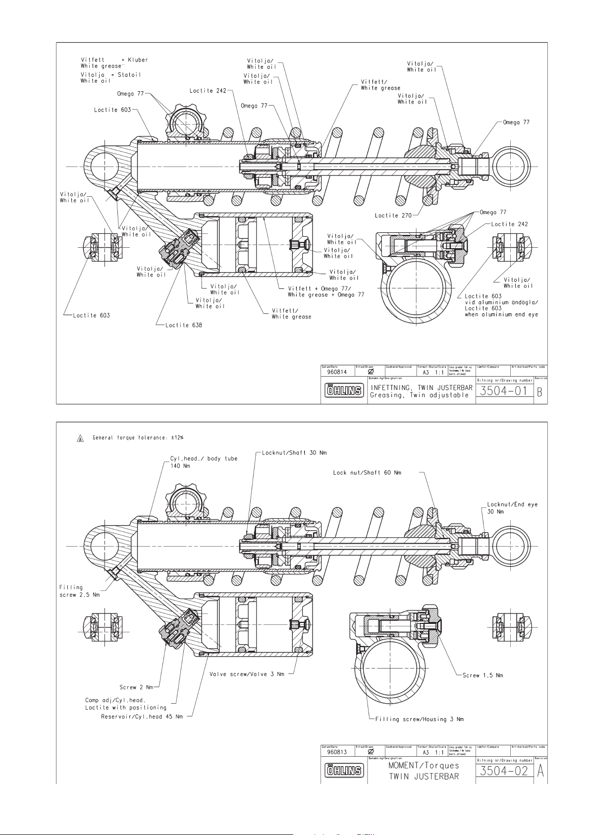
Page 56
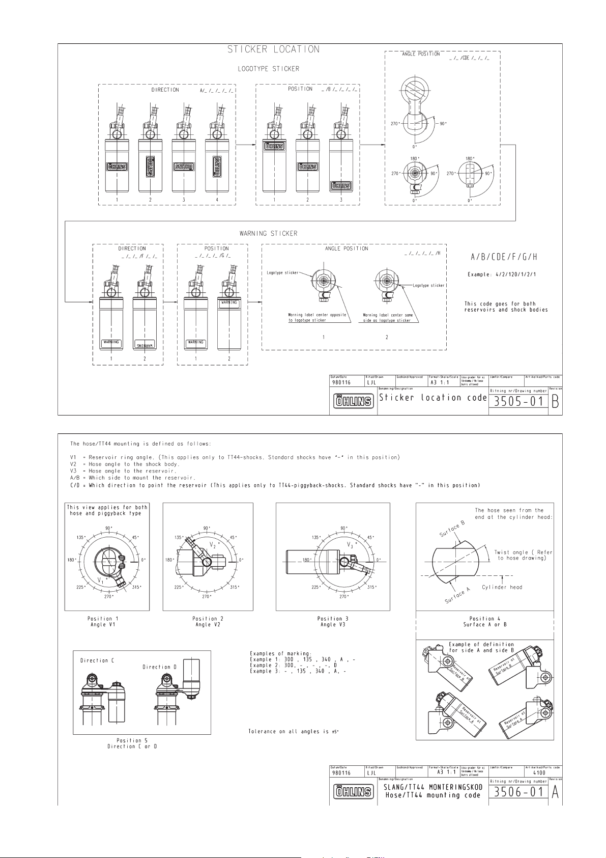
Page 57
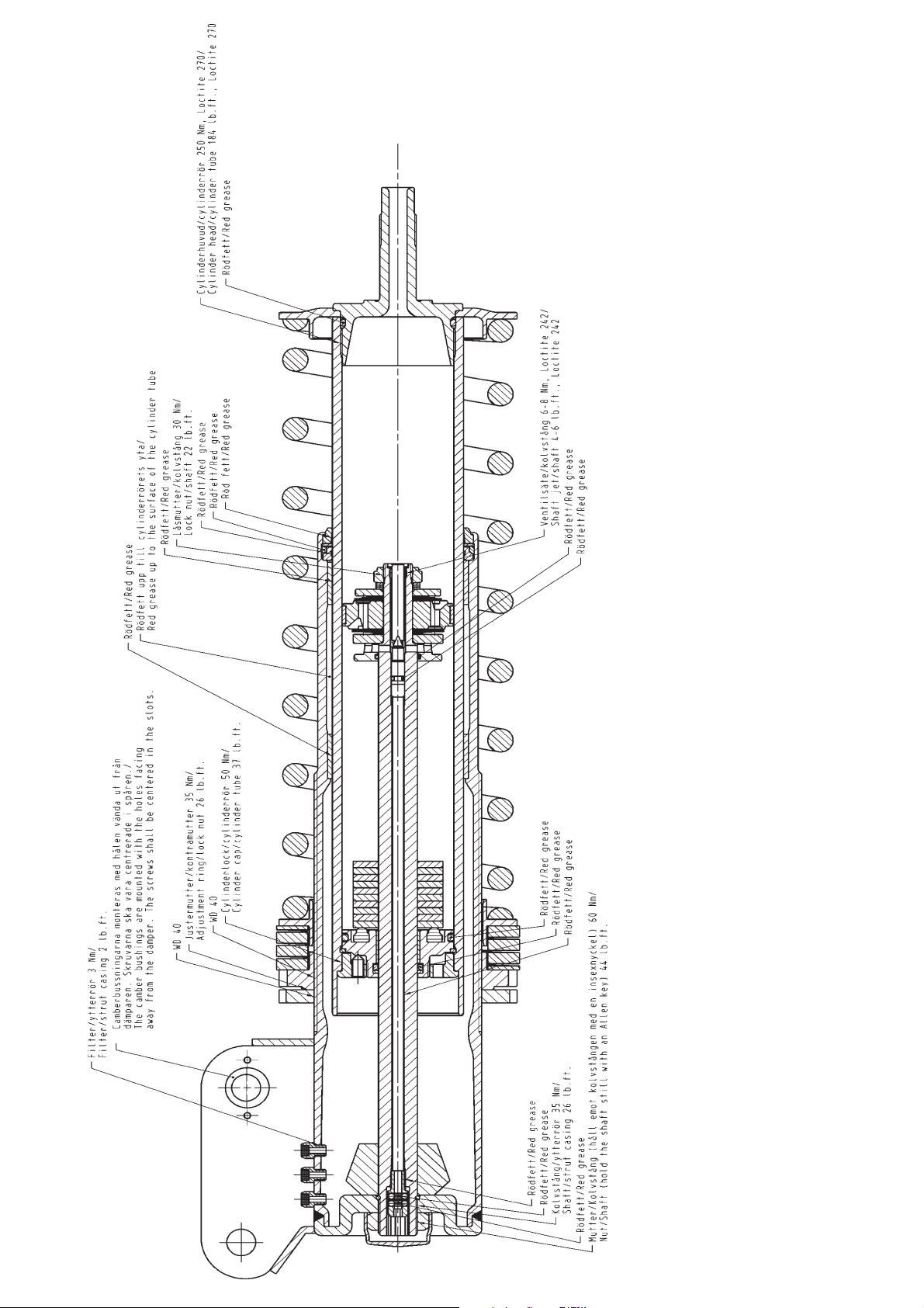
Page 58
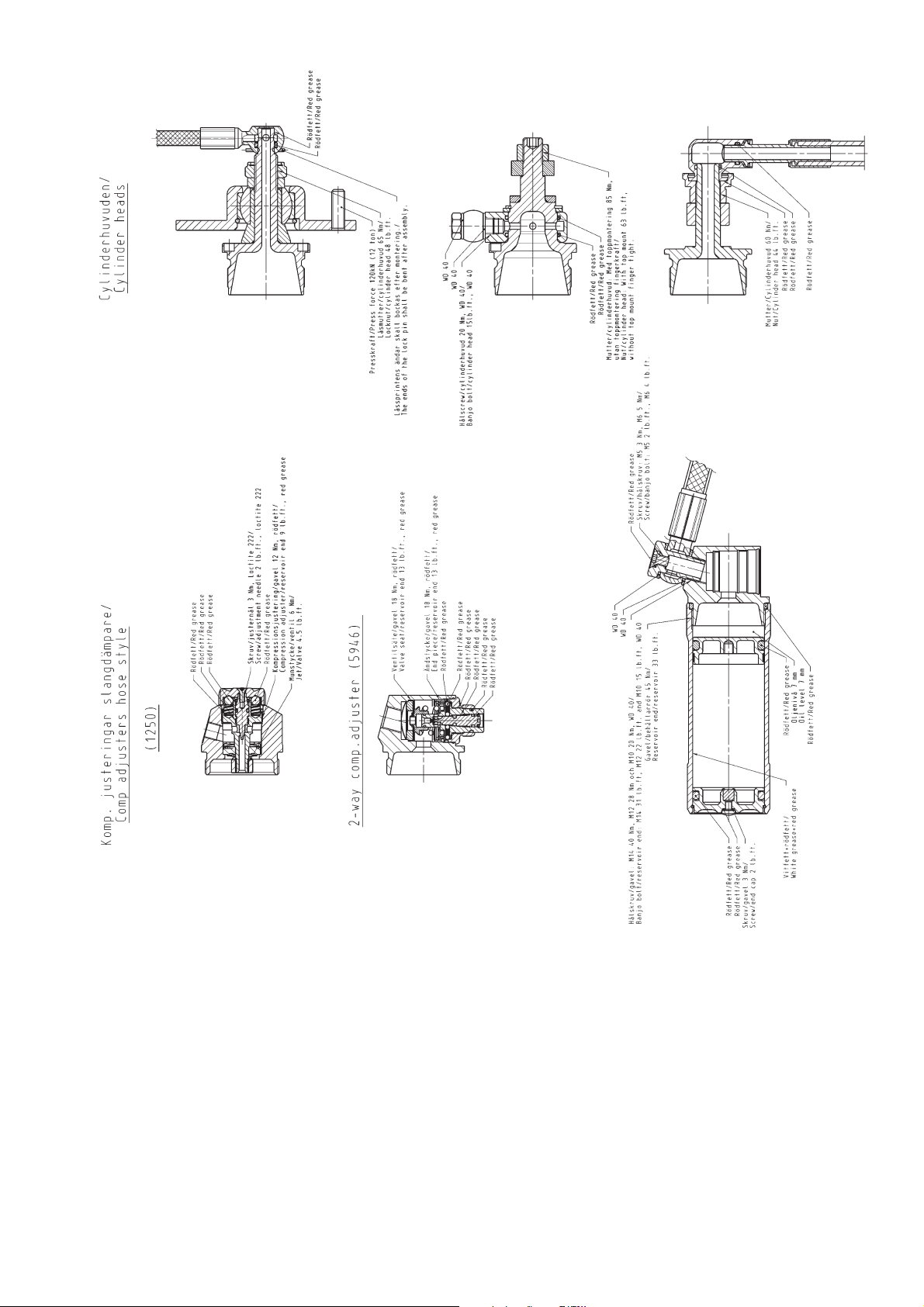
Page 59
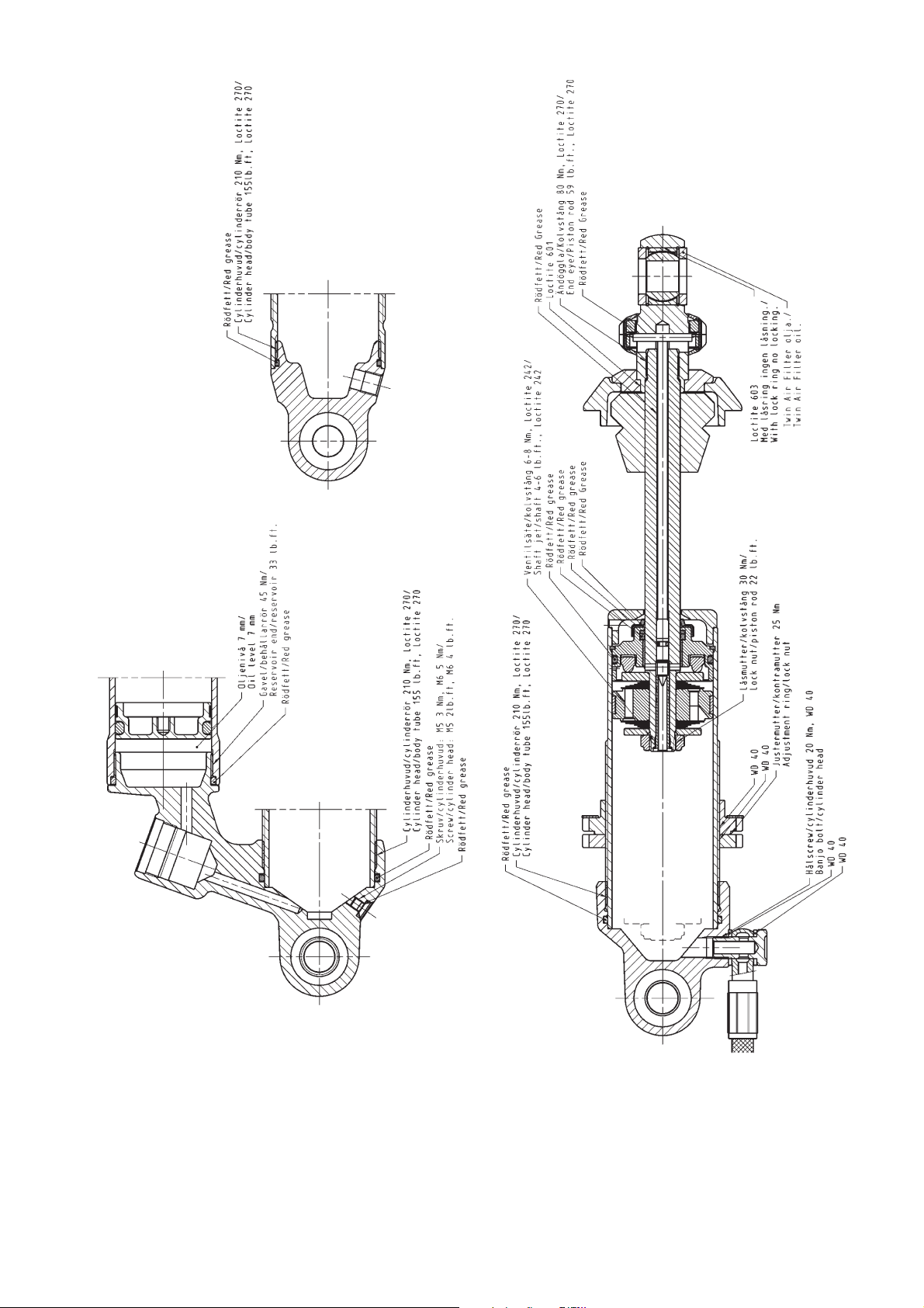
Page 60
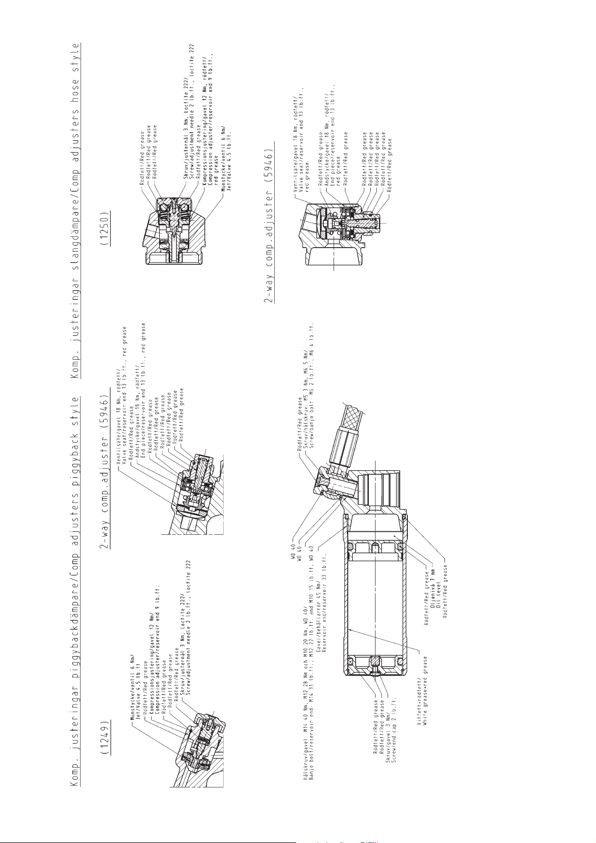
Page 61
More info
www.ohlins.com
The ultimate suspension site.
Find out everything about your suspension.
Download mounting instructions, manuals and brochures.
And a lot more.
Öhlins Racing AB, Box 722, S-194 27 Upplands Väsby, Sweden
Phone +46 8 590 025 00, Fax +46 8 590 025 80
07606-01, Teknisk Illustration AB, 02 11 08. 200 copies
 Loading...