

Page 1
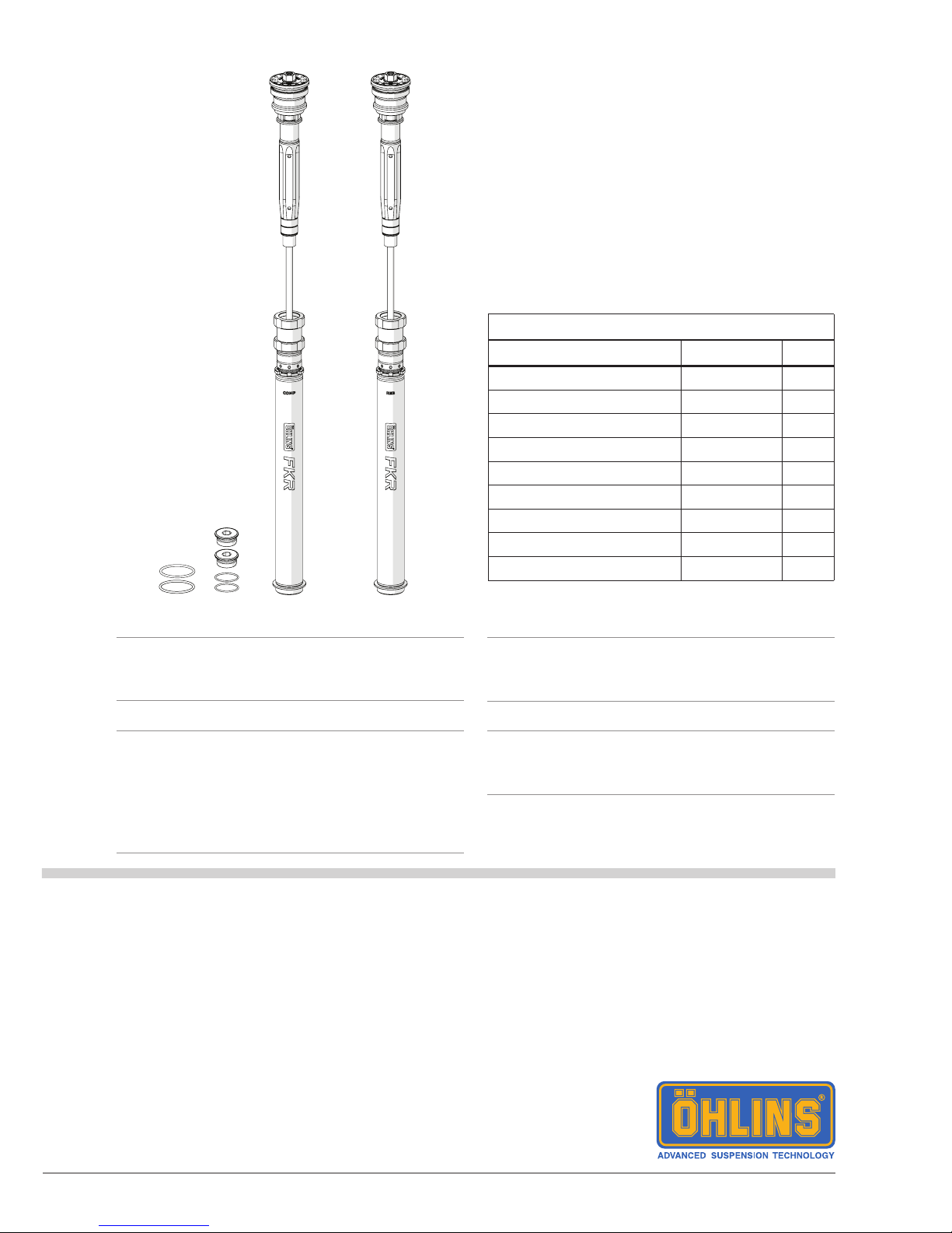
Cartridge kit for Suzuki GSX-R1000
FKR 118
Mounting Instructions
Note!1
Please note that there can be small differences
between your product and the images in
these instructions.
Note!1
Please note that during storage and transport,
especially at high ambient temperature, some
of the oil and grease used for assembly may
leak and stain the packaging. This will not
cause damage to the product, wipe off the
excessive oil or grease with a cloth.
Note!1
Before you install this product, check the kit
contents. If anything is missing, please contact
an Öhlins dealer.
Warning!⚠
Before you install this product, read the Öhlins
Owner’s manual. This product is an important
part of the vehicle and the vehicle stability.
Kit Contents
Description Part No Pcs
Cartridge kit FKR 118 1
O-ring 40x2.5 00576-02 2
O-ring 17x2 00338-40 2
Plug 21652-02 2
Main spring 9.5 N/mm 04744-95 2
Main spring 10.0 N/mm 04744-10 2
Main spring 10.5 N/mm 04744-05 2
Sticker set Öhlins - Owner’s manual 07291-01 1
Page 2
2
MOUNTING INSTRUCTIONS
Tool Part no Applies Size
Vehicle service manual
Torque wrench 10-60 Nm Torque
Heat gun Soften thread locker
Hex key Plug 8 mm
Hex key Compression and
rebound adjuster
3 mm
Extended hex key Cylinder tube assembly 14 mm
Socket Main preload adjuster 14 mm
Wrench Spring support 19 mm
Suspension uid 01309-xx
Grease 00146-01 100 g
Loctite 2400 01791-25 50 ml
Loctite 2700 01791-27 50 ml
Shaft extension tool 01765-03
Seal head tool 01797-07
Clip 02810-01
Top cap tool 00797-08
Inner tube tool 00786-05 43 mm
Warning!⚠
We strongly recommend to let an Öhlins dealer
install this product.
Warning!⚠
If you work with a lifted vehicle, make sure that it
is safely supported to prevent it from tipping over.
Note!1
When you work with this product, see the
vehicle service manual for vehicle specic
procedures and important data.
Note!1
Before you install this product clean the vehicle.
Warning!⚠
Spring compression creates a potential danger
because of the violent force that loaded springs
are capable of. Beware of this when you work
with the front fork.
Page 3
3
MOUNTING INSTRUCTIONS
1 Remove original front fork
Note!1
The following procedure applies to both front
fork legs.
1
Put the motorcycle on a workstand so that the
front wheel barely touches the ground.
Warning!⚠
Make sure the vehicle is securely supported so
that it will not fall over.
2
Remove front fender, brake calipers, speed
sensor (if present) and front wheel.
3
Release main spring preload fully (if present).
4
Note front fork leg position.
5
Loosen upper triple clamp.
6
Loosen (do not remove) top cap ½ turn.
7
Loosen lower triple clamp.
8
Remove front fork legs from triple clamps.
4
Page 4
4
MOUNTING INSTRUCTIONS
2 Disassemble original front fork
Note!1
The following procedure applies to both front
fork legs.
1
Remove top cap from outer tube.
2
Slide outer tube down until it stops.
3
Remove top cap from shaft according to
instructions in the vehicle service manual.
4
Remove seal head from inner tube according
to instructions in the vehicle service manual.
5
Remove main spring and associated parts
according to instructions in the vehicle service
manual.
6
Drain front fork leg from suspension uid.
7
Remove outer tube from inner tube according
to instructions in the vehicle service manual.
8
Remove inner tube lock screw.
Warning!⚠
If lock screw is not removed inner tube and fork
bottom will be damaged.
Warning!⚠
Inner tube thread may need to be repaired
before removing inner tube [apply appropriate
method].
9
Install inner tube tool on inner tube. Do not
place tool at sealing or gliding surface.
[00786-05 inner tube tool]
10
Soften thread locker between inner tube and
fork bottom with a heat gun.
[Heat gun]
11
Remove inner tube from fork bottom.
12
Remove o-ring and washer from fork bottom.
Replace o-ring if worn or damaged.
[Part no according to the vehicle spare part
list]
13
Remove main spring preload adjuster and
associated parts from fork bottom according to
instructions in the vehicle service manual.
Page 5
5
MOUNTING INSTRUCTIONS
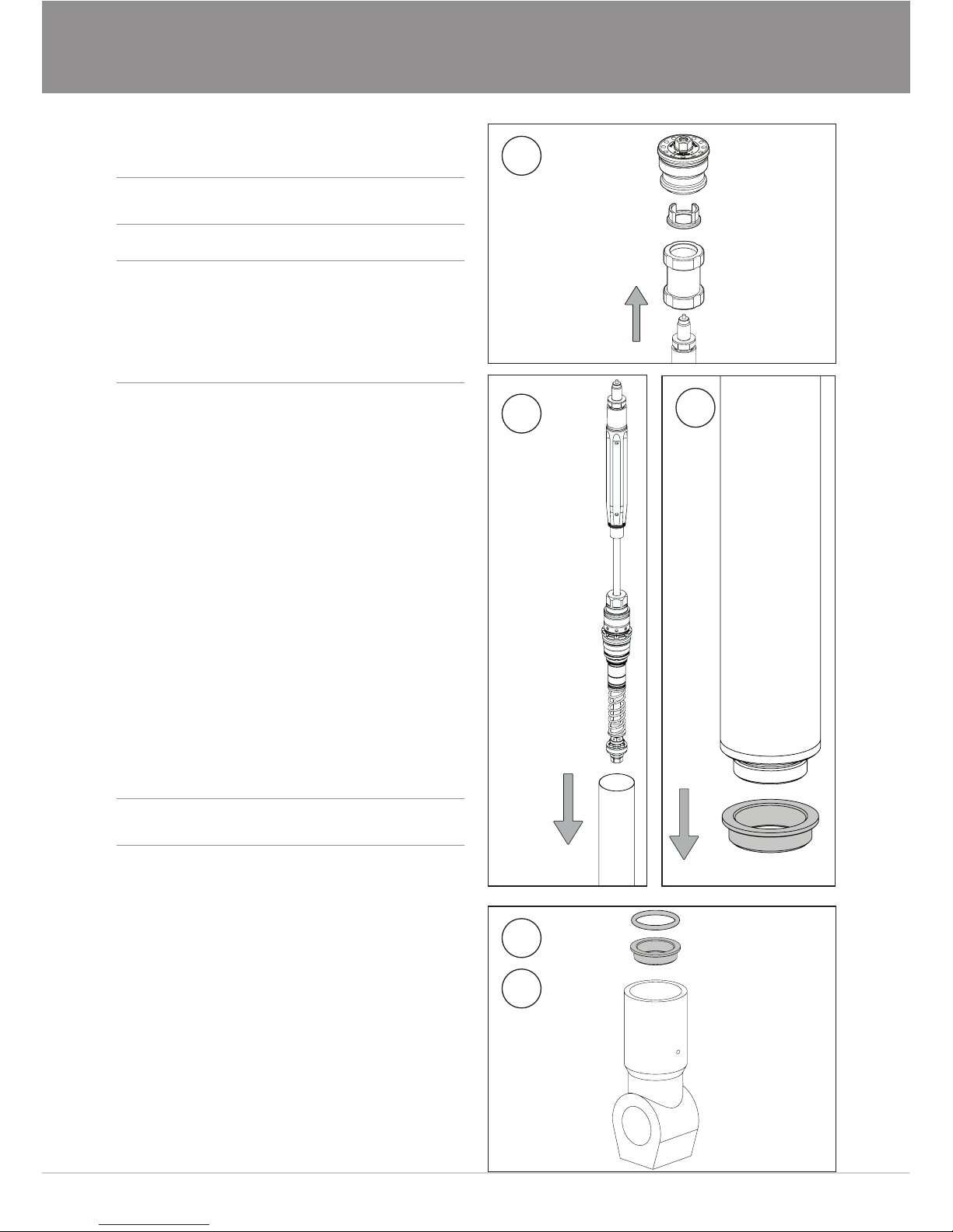
3 Install Öhlins cartridge kit
Note!1
The following procedure applies to both front
fork legs.
Caution!✋
The cartridge kit is divided into compression
and rebound cartridges.
Install compression cartridge marked “COMP”
in left hand side front fork leg.
Install rebound cartridge marked “REB” in right
hand side front fork leg.
1
Remove top cap, spring support and preload
tube.
2
Remove cylinder tube assembly from shaft
assembly.
3
Remove adaptor ring from cylinder tube
assembly.
4
Clean and degrease inner tube, fork bottom
and adaptor ring.
5
Install adaptor ring in fork bottom.
Caution!✋
Make sure to install the adaptor correctly. See
gure 5.
6
Install o-ring in fork bottom. Apply grease on
o-ring.
[00146-01 grease]
2
1
3
5
6
Page 6
6
MOUNTING INSTRUCTIONS
7
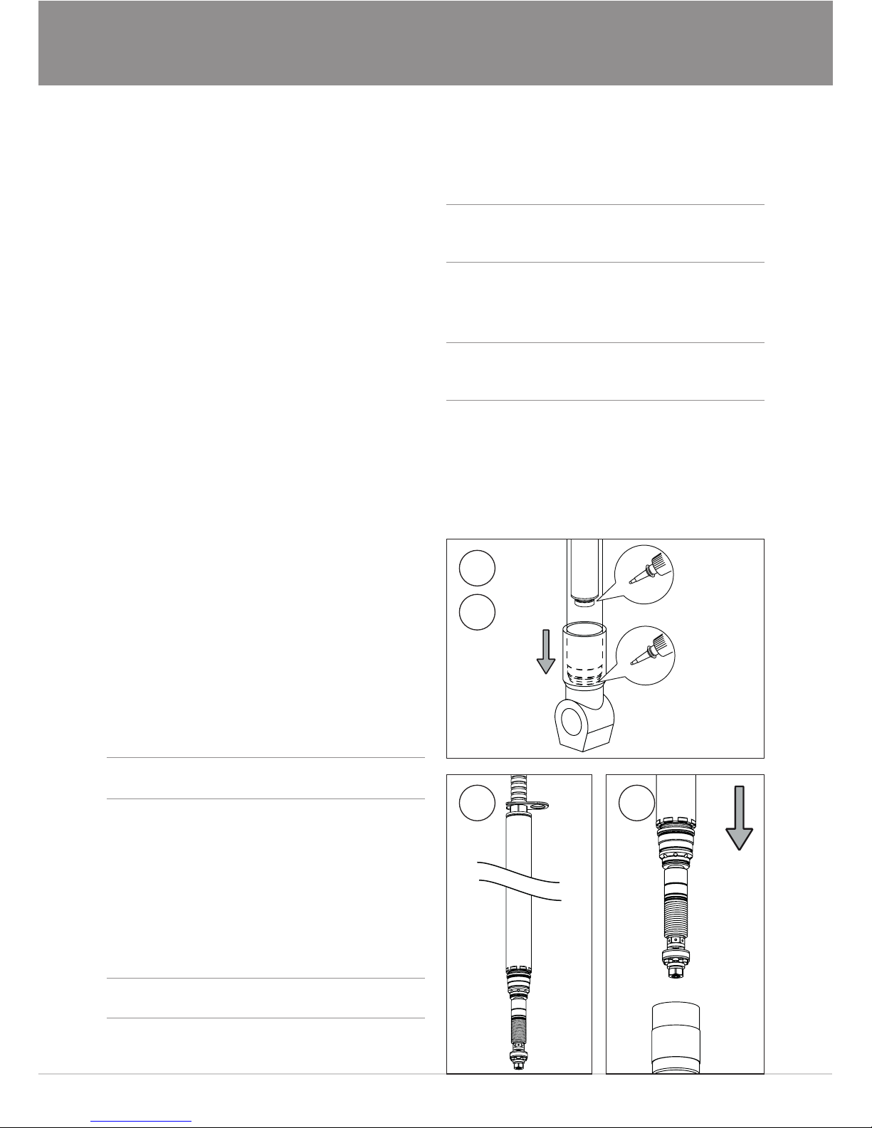
Install inner tube using inner tube tool.
Apply Loctite 2700. Tighten to 130 Nm.
[00786-05 inner tube tool]
[01791-27 Loctite 2700]
8
Install cylinder tube assembly in front fork leg
with an extended hex key. Apply Loctite 2400
on adaptor thread. Tighten to 60 Nm.
[Extended hex key 14 mm]
[01791-25 Loctite 2400]
9
Install o-ring on plug. Apply grease on o-ring
and thread.
[00338-40 o-ring]
[21652-02 plug]
[00146-01 grease]
10
Install plug in fork bottom with a hex key.
Tighten to 12 Nm.
[Hex key 8 mm]
11
Install outer tube according to instructions in
the vehicle service manual.
12
Pour approximately 0.5 litre Öhlins suspension
uid in front fork leg.
Warning!⚠
Fluid level must be approximately 50 mm
above top of cylinder tube assembly.
13
Install tool on shaft extension.
[01765-03 shaft extension tool]
14
Install tool on seal head.
[01797-07 seal head tool]
Note!1
Make sure teeth are securely connected to seal
head.
15 16
8
7
15
Compress top out spring fully and insert clip
[02810-01 clip].
Warning!⚠
If top out spring is not completely compressed,
adjust shaft extension tool to achieve complete
compression of top out spring.
16
Insert shaft assembly in front fork leg.
Warning!⚠
Make sure no air is trapped in piston by
carefully pumping shaft assembly up and down
with piston below uid surface.
17
Install shaft assembly and tighten with your
hand.
18
Remove clip and shaft extension tool.
Page 7
7
MOUNTING INSTRUCTIONS
19
Tighten seal head to 30 Nm and remove seal
head tool.
20
Make sure that shaft assembly and outer tube
are in their bottom positions.
Set suspension uid level according to chapter
“Setup Data”.
21
Install tool on shaft extension.
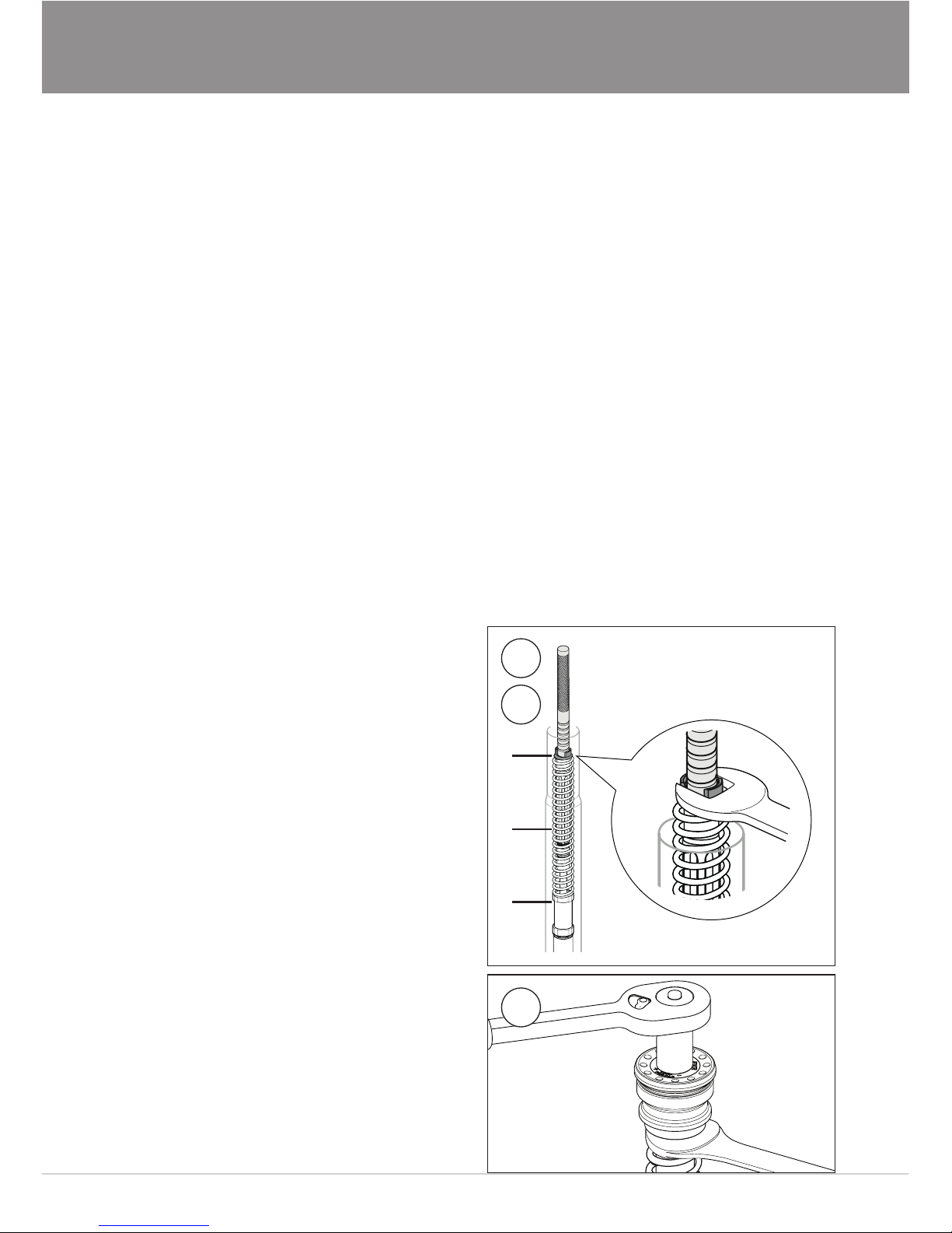
Install preload tube (A), main spring (B) and
spring support (C) over shaft extension
tool. Select main spring according to chapter
“Main spring guide”.
[01765-03 shaft extension tool]
22
Pull up shaft assembly and grab spring support
with a wrench.
[Wrench 19 mm]
23
Remove shaft extension tool.
24
Make sure that compression and rebound
adjusters are fully open before installing top
cap. Use a hex key to open compression and
rebound adjusters.
[Hex key 3 mm]
25
Install o-ring on top cap. Apply grease on o-ring
and thread.
[00576-02 o-ring]
[00146-01 grease]
26
Install top cap on shaft extension. Tighten to
20 Nm.
[Socket 14 mm]
27
Remove wrench from spring support.
26
28
Pull up outer tube. Make sure front fork leg is
in a fully extended position. Use top cap tool to
tighten top cap to outer tube. Tighten to 10 Nm.
[00797-08 top cap tool]
29
Set compression, rebound and main spring
adjusters according to chapter “Setup Data”.
Use a hex key for compression and rebound
adjusters. Use a socket for main spring preload
adjuster.
[Hex key 3 mm]
[Socket 14 mm]
30
Install front fork legs in vehicle at
recommended front fork leg position, according
to chapter “Setup data”.
31
Remaining installation, instructions according
to vehicle service manual.
21
22
A
B
C
Page 8
Öhlins Racing AB
Box 722
S-194 27 Upplands Väsby, Sweden
Phone +46 8 590 025 00
fax +46 8 590 025 80
© Öhlins Racing AB. All rights
reserved. Any reprinting or
unauthorized use without the written
permission of Öhlins Racing AB
is prohibited.
Öhlins products are subject to
continuous improvement and
development, therefore, although
these instructions include the most
up-to-date information available at
the time of printing, minor updates
may occur.
To nd the latest information
contact an Öhlins distributor.
Please contact Öhlins if you have
any questions regarding the
contents in this document.
Part no. MI_FKR118_0
Issued 2017-05-02
0
50
100
150
200
250
300
350
400
450
500
550
0102030405060708090100 110120 130
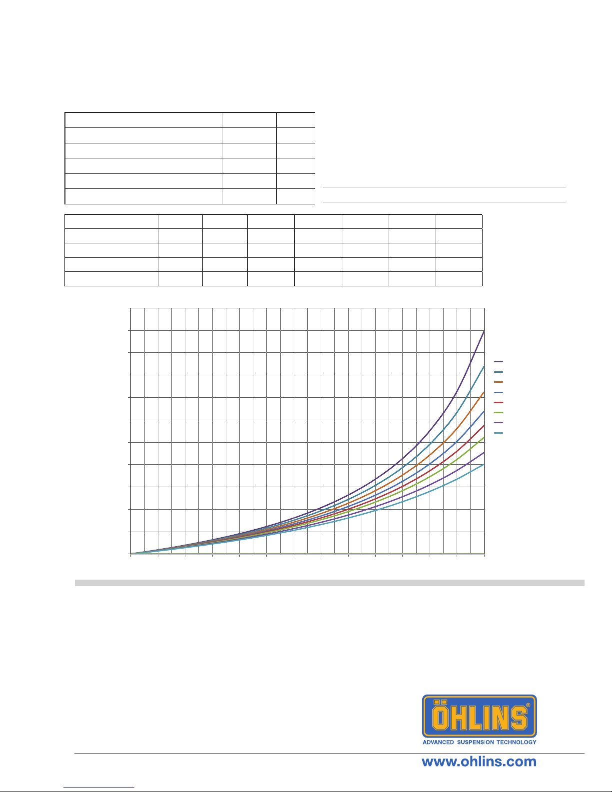
Force [N]
Stroke [mm]
13
0
14
0
15
0
16
0
17
0
18
0
19
0
20
0
Level
SETUP DATA
Recommended setup
MAIN SPRING GUIDE
Compression adjustment 14 clicks
Rebound adjustment 14 clicks
Suspension uid level 180 mm
Minimum suspension uid level 200 mm
Suspension uid part number 01309-xx
Front fork leg position Standard
Make sure you choose the correct main spring for
your rider weight, driving style and preferences.
Below you nd a general recommendation of main
spring rate for your weight. Contact an authorized
Öhlins service center for advice.
Air spring force diagram
Rider weight [kg] 50 60 70 80 90 100 110
Spring rate [N/mm] 9 9 9,5 10 10,5 10,5 11
Preload [mm] 3 5 5 4 4 6 5
Part number (pair) 08790-90 08790-90 08790-95 08790-10 08790-05 08790-05 08790-11
Part number (single) 04744-90 04744-90 04744-95 04744-10 04744-05 04744-05 04744-11
Note!1
Only 8790-xx main springs are packed in pairs.
 Loading...