

Page 1
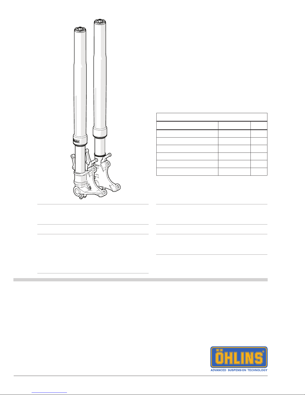
Front Fork for Yamaha YZF-R1
FGRT 219
Mounting Instructions
Note!1
Please note that there can be small differences
between your product and the images in
these instructions.
Note!1
Please note that during storage and transport,
especially at high ambient temperature, some
of the oil and grease used for assembly may
leak and stain the packaging. This will not cause
damage to the product, wipe off the excessive
oil or grease with a cloth.
Note!1
Before you install this product, check the kit
contents. If anything is missing, please contact
an Öhlins dealer.
Warning!⚠
Before you install this product, read the Öhlins
Owner’s manual. This product is an important
part of the vehicle and the vehicle stability.
Kit Contents
Description Part No Pcs
Front fork FGRT219 1
Screw MC6S M5x10 01046-38 8
Fender bracket front 21665-09 2
Fender bracket rear 21665-17 2
Sticker Öhlins 01196-02 1
Owner’s Manual 07282-07 1
Page 2
2
1
Put the motorcycle on a work stand so that the
front wheel barely touches the ground.
2
Remove the front fender, brake calipers, speed
sensor and the front wheel. Refer to the vehicle
service manual for correct procedure.
MOUNTING INSTRUCTIONS
Warning!⚠
We strongly recommend to let an authorized
Öhlins dealer install this product.
Warning!⚠
If you work with a lifted vehicle, make sure that it
is safely supported to prevent it from tipping over.
Note!1
When you work with this product, see the
vehicle service manual for vehicle specic
procedures and important data.
Note!1
Before you install this product clean the vehicle.
3
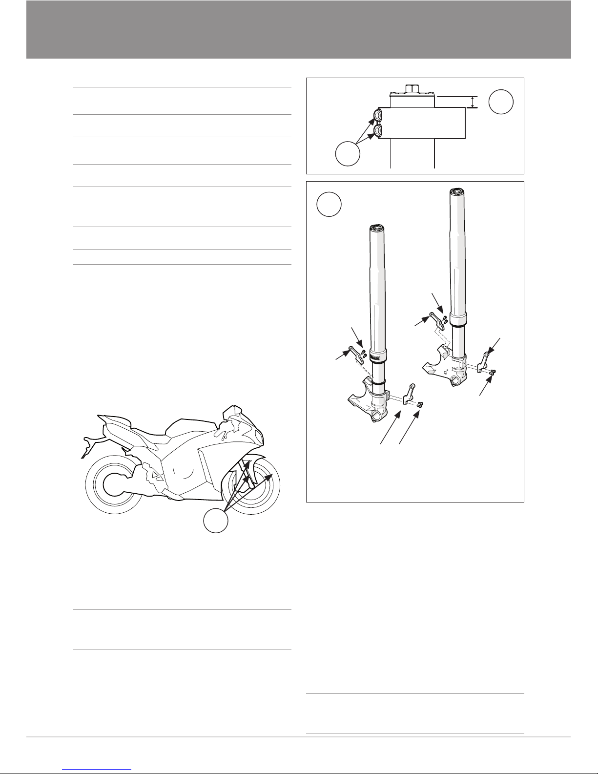
Measure the distance from the top of the outer
fork leg to the top of the upper triple clamp.
Note this distance.
Note!1
It is very important that the Öhlins front fork is
installed at the exact same posiition as the OEM
front fork.
4
Loosen the bolts to loosen the upper and the
lower triple clamps.
5
Remove the fork legs from the motorcycle.
3
6
4
2
6
Apply Loctite 243 or similar to the bolts. Install
the supplied fender brackets to the fork legs,
see gure 6. Tighten the screws to 4 Nm.
7
Install the fork legs in the triple clamps at the
same position as measured in step 3. Turn the
handle bars fully from side to side to make sure
that nothing restricts the movement, and that
the throttle cable and the wire harness run in
smooth bends.
Note!1
The eccentrically machined surfaces on the
outer tube must be at a 90º angle from the
vehicle direction.
Bracket
21665-17
Bracket
21665-17
Bracket
21665-09
Bracket
21665-09
2x bolt
01046-38
Loctite 243
Torque 4 Nm
2x bolt
01046-38
Loctite 243
Torque 4 Nm
2x bolt
01046-38
Loctite 243
Torque 4 Nm
2x bolt
01046-38
Loctite 243
Torque 4 Nm
Page 3
3
MOUNTING INSTRUCTIONS
8
Tighten:
Upper triple clamp: 20 Nm
Lower triple clamp: 10 Nm
9
Install the front fender, front wheel and the
brake calipers. Do not tighten yet.
11
Warning!⚠
Ensure that the speed sensor cable does not
touch the wheel at full lock turns and when the
suspension is fully compressed or extended.
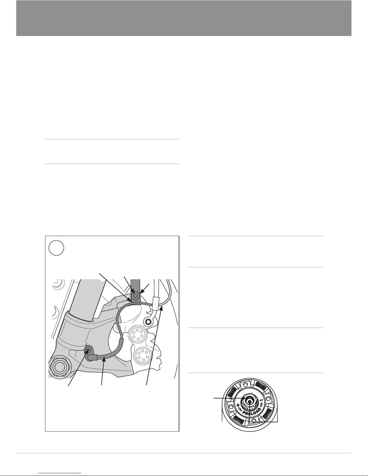
Install the speed sensor bracket:
Place the sensor cable bracket at the rear
screw (position A) that holds the rear fender
bracket. Cable routing according to the gure.
Ensure that the speed sensor cable does not
touch the wheel at full lock turns and when the
suspension is fully compressed or extended.
12
Put the vehicle on the ground, apply the front
brake and compress the front fork distinctly
3-4 times. This will position the front fork legs
parallell.
13
Tighten the front axle, brake calipers and the
front fender.
Front axle pinch bolts torque: 19 Nm
14
Close the compression and rebound adjusters.
15
Compress the front fork as much as possible
several times to bleed out the air. Ensure that
there is damping on the full stroke.
16
Set the compression and rebound adjusters,
see setup data on the next page.
Caution!✋
Make sure that you tighten all screws to the
correct torque and that nothing fouls or restricts
movement of the front fork when the suspension
is fully compressed or extended.
Cable behind
the brake hose
Hose down
towards
the speed
sensor.
Speed sensor
bracket on the
outer side of
the brake hose
attachment.
A
The tab of
the bracket
below the
rear fender
bracket.
Torque and
thread locking
according to
vehicle service
manual.
11
ADJUSTMENTS
Warning!⚠
Before you ride/drive, always make sure that the
setup is according to the recommended setup
data. Read about adjustments and setting up
in the Öhlins Owner’s Manual before you make
any adjustments. Contact an Öhlins dealer if
you have any questions about set up.
Spring
preload
adjuster
Compression/
Rebound
adjuster
Page 4
Öhlins Racing AB
Box 722
S-194 27 Upplands Väsby, Sweden
Phone +46 8 590 025 00
fax +46 8 590 025 80
© Öhlins Racing AB. All rights
reserved. Any reprinting or
unauthorized use without the written
permission of Öhlins Racing AB
is prohibited.
Öhlins products are subject to
continuous improvement and
development, therefore, although
these instructions include the most
up-to-date information available at
the time of printing, minor updates
may occur.
To nd the latest information
contact an Öhlins distributor.
Please contact Öhlins if you have
any questions regarding the
contents in this document.
SETUP DATA
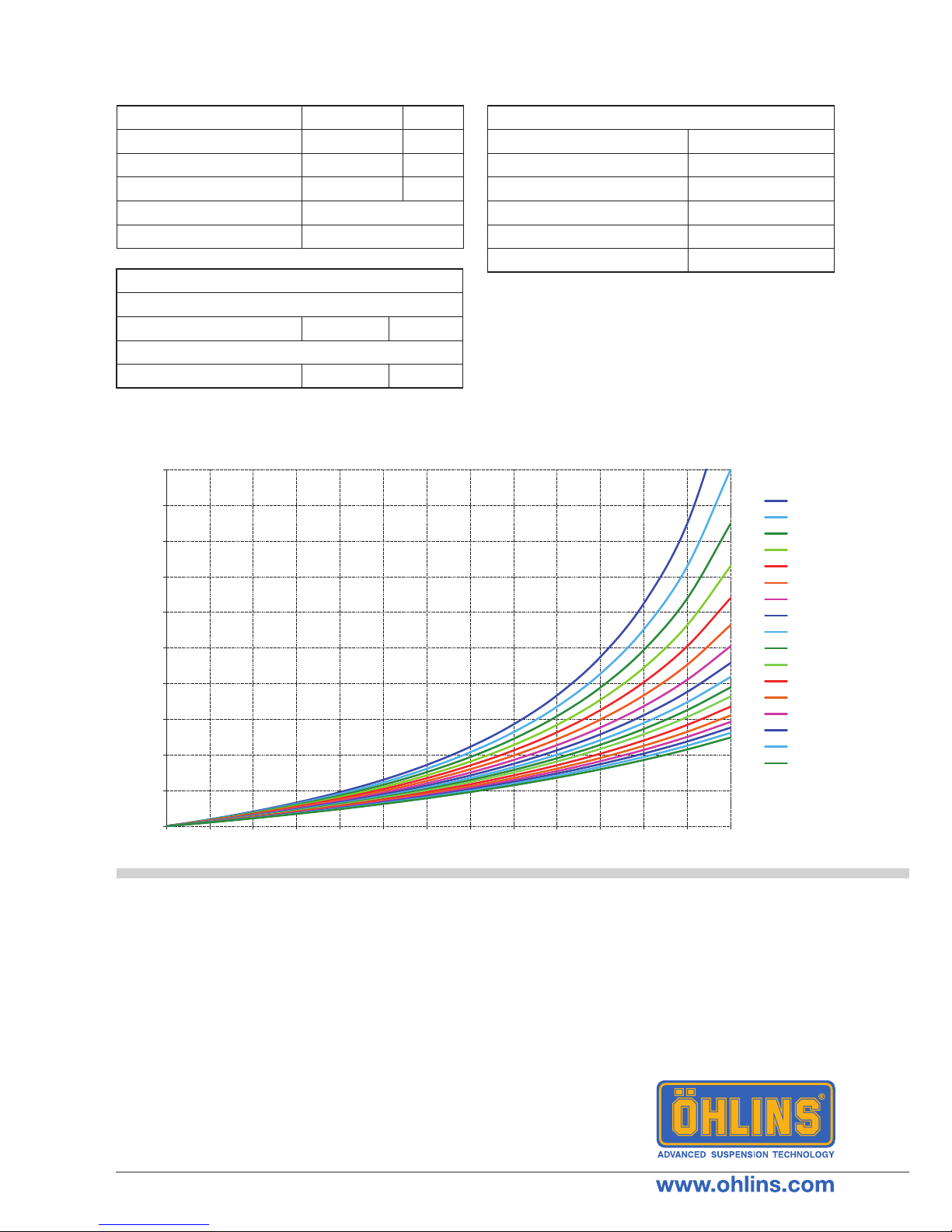
OIL LEVEL - FORCE DIAGRAM
Part no. MI_FGRT219_0
Issued 2015-09-08
Compression 12 clicks
Rebound 12 clicks
Spring preload 6 mm
Oil level 150 mm
Fork leg position Standard position
Öhlins Front fork uid 01309-01
Recommended sag and ride height
No rider (Free sag)
Front 15-30 mm (F1-F2)
With rider (Ride height)
Front 35-50 mm (F1-F3)
Spring
Part No. Rate (N/mm)
04744-95 (optional) 9.5
04744-90 (optional) 9.0
04744-10 (standard) 10.0
04744-05 (optional) 10.5
04744-11 (optional) 11.0
0
50
100
150
200
250
300
350
400
450
500
0102030405060708090100 110120 130
Force [N]
Oil level [mm]
140
150
160
170
180
190
200
210
220
230
240
250
260
270
280
290
300
Air spring for one leg.
 Loading...