

Page 1

ST400 Portable pH Meter and
ST400M Portable Multi Parameter Meter
Instruction Manual
Manuel d'instructions pour
pH-mètre portable ST400 et
pH-mètre multi-paramètres portable ST400M
pH-metro portátil ST400 y
Medidor multiparámetro portátil ST400M
Manual de instrucciones
Find Quality Products Online at: [email protected]
www.GlobalTestSupply.com
Page 2

TABLE OF CONTENTS
1澳 INTRODUCTION...................................................................1澳
1.1澳 Definition of Signal Warnings and Symbols...................................... 1澳
1.2澳 Safety Precautions............................................................................2澳
1.3澳 Display and controls.......................................................................... 3澳
2澳 INSTALLATION.....................................................................6澳
2.1澳 Package contents.............................................................................. 6澳
2.2澳 Meter charging .................................................................................. 8澳
2.3澳 Connect the electrodes..................................................................... 8澳
3澳 ST400 ST400M OPERATION................................................9澳
3.1澳 Menu directory................................................................................... 9澳
3.2澳 Setup...............................................................................................10澳
3.2.1澳 System setup............................................................................ 10澳
3.2.2澳 pH Setting................................................................................. 10澳
3.2.3澳 Conductivity Setting* .................................................................11澳
3.2.4澳 Sensor management................................................................12澳
3.2.5澳 Data management.................................................................... 12澳
3.2.6澳 Factory reset............................................................................. 12澳
3.3澳 pH Calibration.................................................................................. 13澳
3.3.1澳 Buffer group.............................................................................. 13澳
3.3.2澳 Performing 1-point calibration .................................................. 14澳
3.3.3澳 Performing Multi-point calibration............................................. 14澳
3.4澳 pH measurement............................................................................. 14澳
3.4.1澳 pH measurement...................................................................... 14澳
3.4.2澳 mV measurement.....................................................................15澳
3.4.3澳 Temperature measurement...................................................... 15澳
3.5澳 Conductivity calibration*.................................................................. 15澳
3.5.1澳 Setting the standard buffer....................................................... 15澳
3.5.2澳 Conductivity calibration ............................................................ 16澳
3.5.3澳 Conductivity measuring............................................................16澳
3.5.4澳 TDS, Salinity and resistivity measuring.................................... 16澳
3.6澳 Two-parameter measurement* ....................................................... 17澳
3.7澳 Using the memory...........................................................................17澳
3.7.1澳 Storing a reading......................................................................17澳
3.7.2澳 Review from memory ............................................................... 17澳
3.7.3澳 Clearing the memory................................................................ 17澳
3.7.4澳 Export the stored data..............................................................17澳
4澳 MAINTENANCE..................................................................18澳
4.1澳 Error message................................................................................. 18澳
4.2澳 Meter maintenance.......................................................................... 18澳
4.3澳 Electrode maintenance ................................................................... 19澳
5澳 TECHNICAL DATA.............................................................19澳
5.1澳 Specifications................................................................................ 19澳
Find Quality Products Online at: [email protected]
www.GlobalTestSupply.com
Page 3

5.2澳 Compliance ..................................................................................... 23澳
6澳 Appendix ............................................................................24澳
6.1澳 Table 1 BUFFER GROUP............................................................... 24澳
6.2澳 Table 2 Examples of temperature coefficients (α-value) .............. 26澳
6.3澳 Table 3 Conductivity standards....................................................... 27澳
Find Quality Products Online at: [email protected]
www.GlobalTestSupply.com
Page 4

ST400 & ST400M Portable Meter EN-1
General hazard
Explosion hazard
Corrosive hazard
~
Alternating current
Direct current
1 INTRODUCTION
Thank you for choosing OHAUS.
Please read the manual completely befo re using the ST400 portable pH and ST400M portable pH
& conductivity meter to avoid incorrect operation.
ST400 series have an excellent performance and are designed with man y useful features. O haus
also offers other accessories such as electrodes for different applications as well as buffer
solutions.
ST400 & ST400M have many unique designs: including IP67 waterproof and dustproof design,
rechargeable lithium battery; large LCD display, data storage, and indication of electrode status.
You will find more practical features of the ST400 & ST400M in use. Some of these features
include:
Ь pH and conductivity* measurements with 1000 sets of data storage;
Ь Dot matrix LCD display, showing a clear reading;
Ь Multiple sets of pH buffer groups and multiple conductivity standards*, adaptable to your
different needs;
Ь Work with Ohaus IP67 pH electrode and conductivity electrode*, truly waterproof and suitable for
harsh environments.
* Only applies to ST400M.
1.1 Definition of Signal Warnings and Symbols
Safety notes are marked with signal words and warning symbols. These show safety issues and
warnings. Ignoring the safety notes may lead to personal injury, damage to the instrument,
malfunctions and false results.
Signal Words
WARNING For a hazardous situation with medium risk, possibly resulting in
CAUTION For a hazardous situation with low risk, resulting in damage to the
Attention For important information about the product.
Note For useful information about the product
Warning Symbols
injuries or death if not avoided.
device or the property or in loss of data, or injuries if not avoided.
Find Quality Products Online at: [email protected]
www.GlobalTestSupply.com
Page 5

EN-2 ST400 & ST400M Portable Meter
1.2 Safety Precautions
CAUTION: Read all safety warnings before installing, making connections, or
servicing this equipment. Failure to comply with these warnings could result in
personal injury and/or property damage. Retain all instructions for future reference.
z Verify that the AC adapter's input voltage range and the plug type are compatible with the
local AC mains power supply.
z Make sure that the power cord does not pose a potential obstacle or tripping hazard.
z Do not position the equipment such that it is difficult to reach the power connection.
z Operate the equipment only under ambient conditions specified in these instructions.
z Do not operate the equipment in hazardous or unstable environments.
z Disconnect the equipment from the power supply when cleaning.
z Use only approved accessories and peripherals.
z When shipping or transporting this product, follow the applicable regulations for equipment
containing lithium-ion batteries.
z Service should only be performed by authorized personnel.
Intended Use
Use the equipment exclusively for measuring the parameters described in these operating
instructions. Any other type of use and operation beyond the limits of technical specifications,
without written consent from OHAUS, is considered as not intended.
This instrument complies with current industry standards and the recognized safety regulations;
however, it can constitute a hazard in use.
If the instrument is not used according to these operating instructions, the intended protection
provided by the instrument may be impaired.
Find Quality Products Online at: [email protected]
www.GlobalTestSupply.com
Page 6
ST400 & ST400M Portable Meter EN-3
2
1
3
7
9
10
456
8
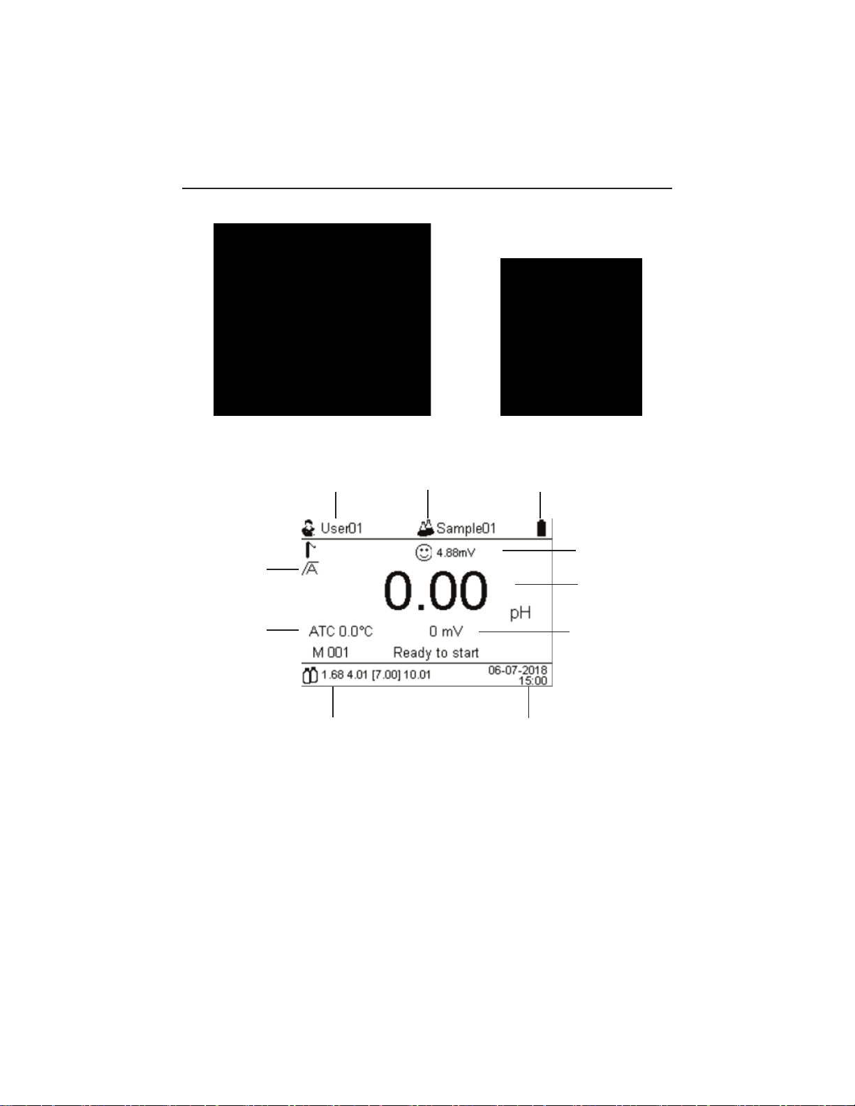
1.3 Display and controls
Connections
*Only applies to ST400M
pH Displays
1. User ID
2. Sample ID
3. Battery status icon
4. Endpoint mode
5. Electrode slope and offset
6. pH
7. ATC or MTC, temperature
8. mV
9. Calibrated pH points
10. Date and time
Find Quality Products Online at: [email protected]
www.GlobalTestSupply.com
Page 7
EN-4 ST400 & ST400M Portable Meter
5
2
3
1
4
9
8
6
10
7
pH/mV
Conductivitiy/
TDS/
Salinity/
Resistivity
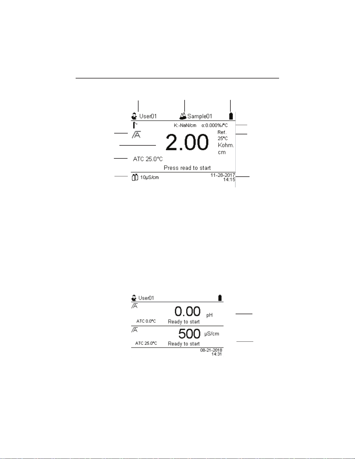
Conductivity Displays*
1. User ID
2. Sample ID
3. Battery status icon
4. Endpoint mode
5. Cell constant (K) and temperature correction coefficient value
6. Reference temperature
7. Conductivity / TDS / Salinity /
8. ATC , temperature
9. Calibrated conductivity point
10. Date and time
Resistivity
Two-parameter Displays*
*Only applies to ST400M
Find Quality Products Online at: [email protected]
www.GlobalTestSupply.com
Page 8
ST400 & ST400M Portable Meter EN-5
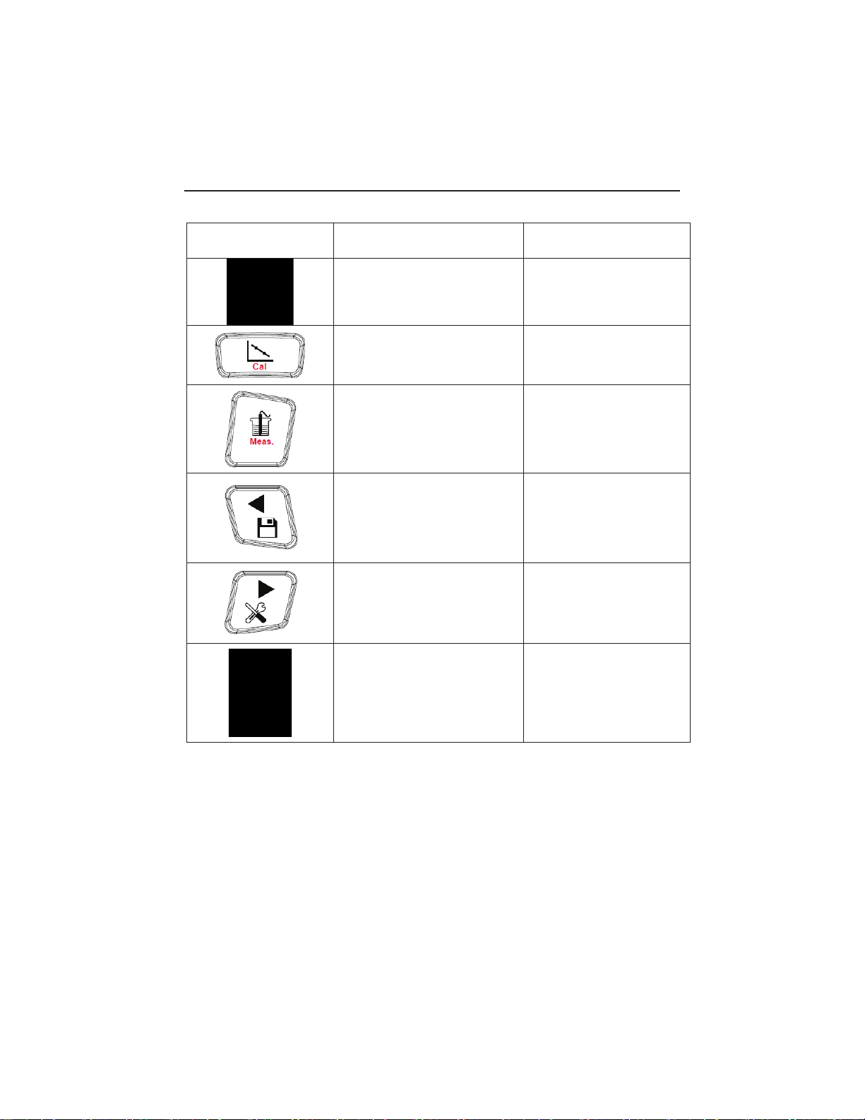
button
Press & release
Press & hold for 3
seconds
Exit and return to
Meter turn on/turn off
Start calibration
Start or stop measurement
- Store current reading to
Scroll up through the memory
- Switch pH and conductivity*
Enter setup mode
- Increase value during setting
switch between Conductivity,
TDS, Salinity and Resistivity*
mV
Controls
measurement screen
memory
-
- confirm setting
- Decrease value during
setting
-
- switch between pH and
*Only applies to ST400M
Find Quality Products Online at: [email protected]
www.GlobalTestSupply.com
Page 9

EN-6 ST400 & ST400M Portable Meter
STARTER 400 /B
Units
Remarks
ST400
1
Rubber cover
1
Adapter 5V
1
Nylon, Belt
1
USB cable
1
STARTER 400 /F
Units
Remarks
ST400/B
1
IP67 ST320 1
3-in-1 plastic refillable pH
Electrode, 3 m cable
Buffer powder set
1
4.01˗7.00˗10.01
STARTER 400 /G
Units
Remarks
ST400 /F
1
Portable bag
1
2 INSTALLATION
Carefully remove your meter and each of its components from the box.
2.1 Package contents
ST400 is available in three different package configurations:
ST400 /B is the basic package, doesn't contain electrodes;
In addition to ST400/B content, ST400/F package also include the electrode and buffer powder. .
In addition to ST400/F content, ST400 /G also includes a portable bag.
Find Quality Products Online at: [email protected]
www.GlobalTestSupply.com
Page 10

ST400 & ST400M Portable Meter EN-7
STARTER 400M /B
Units
Remarks
ST400M
1
Rubber cover
1
Adapter 5V
1
Nylon, Belt
1
USB cable
1
1413 μS/cm standard solution
1
standard solution, only use
once
12.88 mS/cm standard solution
1
STARTER 400M /F
Units
Remarks
ST400M /B
1
IP67 ST320 1
3-in-1 plastic refillable pH
Electrode, 3 m cable
IP67 STCON3 1
Optimal detection
range:
70μS/cm ~200mS/cm,
3m cable
Buffer powder set
1
4.00; 7.01; 10.01
STARTER 400M /G
Units
Remarks
ST400M /F
1
Portable bag
1
ST400M is available in three different package configurations:
ST400M /B is the basic package, including portable meter, doesn't contain electrodes;
In addition to ST400M/B, ST400M /F also includes IP67 ST320 electrode and STCON3 electrode.
In addition to ST400M/F, ST400M /G also includes a portable bag.
Each pH buffer powder should be dissolved in 250ml pure water or deionized water in a
volumetric flask. You can also order the bottled buffer solution from Ohaus.
Additional electrodes, solutions, accessories and spare parts are available. Please contact
Ohaus for more details.
Find Quality Products Online at: [email protected]
www.GlobalTestSupply.com
Page 11

EN-8 ST400 & ST400M Portable Meter
2.2 Meter charging
The ST400 and ST400M are rechargeable portable meters. The real-time power supply status will
be displayed on the uppe r right corner of the screen. The red light on the upper left corner of the
screen will be flashing to indicate low power, which reminds user to charge the meter. The
charging port is located on the right side of the meter, which can be accessed by pulling out the
rubber protection cover. To charge the meter, connect the Micro -USB end of the ch arging cable t o
the charging port and the USB type A end to the AC adapter, or to the USB port of a personal
computer. The normal full charging time is about 8 hours, and the red light in upper left corner will
turn into a blue light when the battery is full.
CAUTION: This product contains a lithium-ion battery.
x Only charge the battery when the ambient temperature is between 5°C and
40°C (41° F and 104 °F)
x Stop charging the battery if charging is not completed within the specified time.
x Stop using the product if the battery becomes abnormally hot, or if there is an
oder, discoloration or deformation.
x Stop using the product if abnormal conditions are detected during use, charging
or storage.
2.3 Connect the electrodes
There are 3 sockets for the electrode. “pH” socket (IP67,BNC); “TEMP.” Socket (IP67, Cinch) and
“IP67, LTW” Socket for conductivity electrode*.
For ST320 3-in-1 electrode, connect both the BNC and Cinch socket.
*Only applies to ST400M
Find Quality Products Online at: [email protected]
www.GlobalTestSupply.com
Page 12
ST400 & ST400M Portable Meter EN-9
Setup
User ID
Sample ID
Language
Date & Time
Backlight
Beep
Auto power off
Settings
Temperature compensation
Temperature
Temperature unit
Buffer group
Continuous measurement
End point
Sensor ID
Conductivity
Calibration standard
Reference temperature
Temperature unit
Alpha-Coefficient
TDS factor
End point
Sensor ID
management
Review
Create
Delete
Data
management
Review
Delete
et
Reset settings
Reset all
User help
3 ST400 ST400M OPERATION
Long press button for 2 seconds to turn on the meter.
After turning on the meter, the default mode is pH mode, press ▲ button and ▼ button to switch
between pH and mV, press
button to switch between Conductivity, TDS, Salinity, Resistivity*.
button to switch to conductivity mode, press ▲ button and ▼
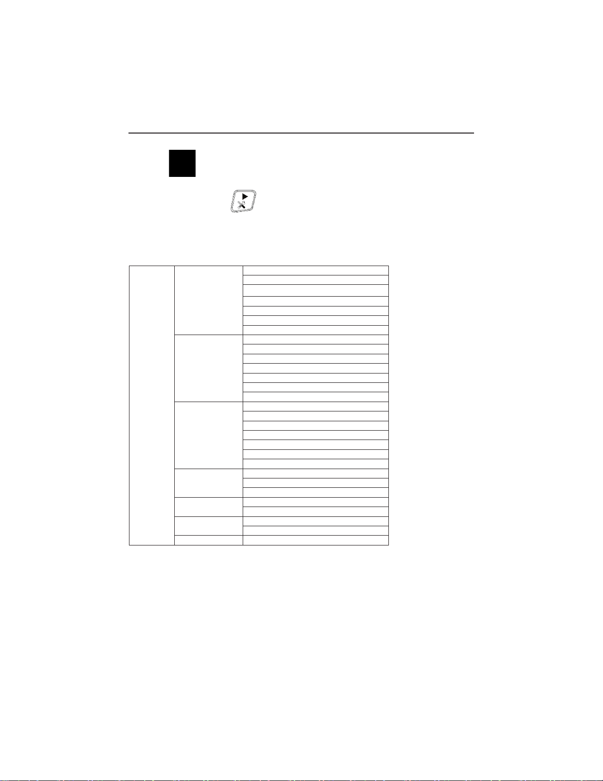
3.1 Menu directory
The menus of first and secondary directory for STARTER 400/400M:
System
settings
pH
Settings*
Sensor
Factory res
澽Only applies to ST400M portable meter
Find Quality Products Online at: [email protected]
www.GlobalTestSupply.com
Page 13

EN-10 ST400 & ST400M Portable Meter
θ
3.2 Setup
3.2.1 System setup
In the measurement mode, long press button (more than 3 seconds) to enter the setup
mode. Press ▲ button and ▼ button to select the system settings, press
the system settings.
User IDθ
numbers or uppercase or lowercase letters), press ▲ button and ▼ button to select the desired
user ID you want to set, long press
select between uppercase letters, numbers and lowercase letters, press
current selection, it will automatically jump to the next character. When the settings are completed,
press the
Sample ID, the system can set up to five sample IDs (less than 8-bit characters, which can be
numbers or uppercase letters or lowercase letters). The user can change the ID according to the
method mentioned above.
Language, system is built-in with six languages (English, German, French, Spanish, Italian,
Chinese), press ▲ button and ▼ button to select, press to confirm.
Date and Time, press ▲ button and ▼ button to change the time and date, date format, time
format.
Backlight, press ▲ button and ▼ button to select between Low, Medium, High, Off. Press
Beep, press ▲ button and ▼ button to select on or off.
Auto power off, press Ȑ button and Ȓ button to select on or off. When auto power off is on, the
meter will automatically shut down when no operation in 15 min (Not in continuous measurement
mode).
the system allows a maximum of 5 user IDs.(less than 8-Bit characters, it can be
,the cursor blinks, press ▲ button or ▼ button to
button to confirm the settings and return to the parameter settings.
to confirm.
button to enter
to confirm the
3.2.2 pH Setting
In the setup mode, press ▲ button and ▼ button to select pH settings, press to enter the
pH settings. There are the following settings:
Temperature compensation (ATC automatic temperature compensation or MTC manual
temperature compensation); the electrode with built-in temperature probe is recommended, If you
use 2-in-1 electrode to measure pH, it is recommended to work with a temperature probe.
Unnecessary measurement errors can be avoided in the ATC mode.
Find Quality Products Online at: [email protected]
www.GlobalTestSupply.com
Page 14

ST400 & ST400M Portable Meter EN-11
Temperature (MTC mode); if MTC mode is used, all buffers and sample solutions should be kept
at the same setting temperature as far as possible.
In order to ensure accurate measurement of the pH value, the pH electrode should be regularly
calibrated.
Temperature unit, Celsius or FahrenheitϹNote: °C = 5/9 (°F - 32)
Buffer groups, users can choose between United States, Europe, MERCK, DIN19266, DIN19267
and other buffer groups, see the appendix.
Continuous measurement, users can choose switch on or off the continuous mode.
choose to use continuous measurement, you need to set the timing value which means how long
an endpoint result will be recorded, the default timing value is 15s which means the meter will
record results every 15 seconds. When you return to pH measure screen, "continuous measure"
will show.
Note: After the continuous measurement is completed, please export the data and empty the
instrument memory. The continuously measured data cannot be displayed on the meter.
End point : automatic end-point or manual end-point mode.
In the manual end-point mode, the meter will always show “measuring” before pressing the
measure-button. If reading is no longer changed by artificial judgment, then press
button to confirm the reading, the meter will show “measurement finished”.
In the automatic end-point mode, performing measurement or calibration, the meter will
display “measuring or calibrating”. The meter can determine the endpoint automatically, then
display “measurement finished”.
Endpoint criteria: pH measurement: (Low)-The signal may not change by more than 0.6
mv/0.6pH in 4 seconds. (medium) ² The signal may not change by more than 0.15mV/0.1pH
in 6 seconds. (High)-The signal may not change by more than 0.18mV/0.18 pH in 8 seconds.
Conductivity measurement- input signal may not change by more than 0.4% from the
average conductivity of the probe in 6 seconds.
Sensor ID, user can view the sensor ID
If you
3.2.3 Conductivity Setting*
In the setup mode, press ▲ button, ▼button and button to enter conductivity setting.
There are the following settings:
Calibration standard: User can select calibration standard between 10, 84, 500, 1413, 12880
μs/cm, which is closest to the sample value.
Reference temperature: the temperature used in temperature compensation, default value is
25°C
Find Quality Products Online at: [email protected]
www.GlobalTestSupply.com
Page 15

EN-12 ST400 & ST400M Portable Meter
Temperature unit, Celsius or FahrenheitϹNote: °C = 5/9 (°F - 32)
Alpha-Coefficient: For different samples, the conductivity value varies with temperature.
Generally, the default value of Alpha-Coefficient for ordinary water sample is 2%/ °C. If you set the
temperature correction coefficient value as 0 %/°C, that means NO Temperature Compensation
for the conductivity measurement. The meter displays the real conductivity value at current
temperature.
confirm the temperature of the sample.
TDS factor: The conversion coefficient that was converted from the conductivity to the TDS.
Endpoint: you can choose automatic end-point mode or manual end-point mode. The rule of
automatic conductivity end-point is that the temperature change doesn’t exceed 0.3 degrees and
the numerical value (conductance, TDS or salinity value) change doesn’t more than 5 within 12
seconds.
Sensor ID, user can view the sensor ID
*only apply to ST400M
The temperature correction coefficient of different samples is different. Please
3.2.4 Sensor management
In the setup mode, press Ȑ button, Ȓ button and button to enter sensor management, to
review, create or delete electrode ID.
pH electrode or conductivity electrode can set five IDs and one default ID. The calibration data is
stored according to the electrode ID, and each ID can store last calibration records.
Review, press Ȑ button andȒ button to choose sensor type (pH or conductivity*), select the
sensor to review the calibration data.
Create, press Ȑ button andȒ button to choose sensor type (pH or conductivity*),then follow the
cursor press Ȑ button andȒ button to name the sensor.
Delete, press Ȑ button andȒ button to choose sensor type (pH or conductivity*), select and
delete the sensor and its calibration data.
3.2.5 Data management
In the setup mode, press Ȑ button, Ȓ button and button to enter data management, to
review or delete data.
The stored measurement data records include as follow:
Date, time, user ID, sample ID, electrode ID, measurement results, measurement mode,
measurement temperature, end-point mode, * reference temperature (cond uctivity), * temperature
correction coefficient (conductivity).
The meter can restore 1000 measurement records. For ST400M, the conductivity and pH records
can be added to 1000 storage records.
3.2.6 Factory reset
Reset settings: Reset user ID, backlight, pH setting, conductivity setting, etc. Please restart the
instrument after confirmation.
Find Quality Products Online at: [email protected]
www.GlobalTestSupply.com
Page 16

ST400 & ST400M Portable Meter EN-13
1
1.68
4.01
7.00
10.0122.00
4.01
7.00
9.21
11.0032.00
4.00
7.00
9.00
12.0041.680
4.008
6.865
9.184
12.454
5
1.09
4.65
6.79
9.23
12.7561.680
4.003
6.864
9.182
12.460
5 °C
1.67
4.00
6.95
9.39
13.21
10 °C
1.67
4.00
6.92
9.33
13.01
15 °C
1.67
4.00
6.90
9.28
12.82
20 °C
1.68
4.00
6.88
9.23
12.64
25 °C
1.68
4.00
6.86
9.18
12.46
30 °C
1.68
4.01
6.85
9.14
12.29
35 °C
1.69
4.02
6.84
9.11
12.13
40 °C
1.69
4.03
6.84
9.07
11.98
45 °C
1.67
4.00
6.95
9.39
13.21
50 °C
1.67
4.00
6.92
9.33
13.01
Reset all: Reset settings and delete all the calibration and measurement data. Please restart the
instrument after confirmation.
3.3 pH Calibration
3.3.1 Buffer group
Meters can perform 1-5 point calibrations.
x The pu rpose of the calibration is to convert the corresponding electrical signal (mV value) of
the pH electrode to a pH value. As the electrode storage time becomes longer or the
electrode being constantly used, the electrical signal of the same electrode in the same
sample (such as standard buffer) will be different, so regular calibrations are required.
x Calibrate the pH electrode for the first use or after a period of time.
There are 6 buffer groups built-in the meter, you can select the buffer group in the pH settingė
buffer group, default buffer group is [OH US] (US standard), and the buffer value will be
automatically recognized during calibration.
The 6 predefined buffer groups are (at 25°C):
For example, after the sixth group is selected, the meter uses the data in the following table to
calibrate the actual value of the buffer corresponding to the real-time temperature during
calibration at 0.01 pH accuracy. E.g. a pH 9.18 buffer solution is calibrated at 20 °C. The
instrument should display the calibration value of 9.23. See the Appendix for the table of other
buffer changes with temperature:
Find Quality Products Online at: [email protected]
www.GlobalTestSupply.com
Page 17

EN-14 ST400 & ST400M Portable Meter
3.3.2 Performing 1-point calibration
Place the pH electrode in the buffer, and press button to enter the calibration mode,
and continue to press
"calibrating" is displayed at the bottom of the screen, and the
screen. After the first calibration point complete, “press the calibration button to continue
calibration” will be displayed at the bottom of the screen. The corresponding calibration buffer is
displayed and stored.
The 1-point calibration is finished. There are now 2 options (OHAUS recommends conducting at
least a 2-point calibration);
1. When performing calibration, Ohaus recommends using Auto End Point Mode.
Press button-
2. Press buttonshown on the top right corner of the screen then return to the measurement screen.
Note: With the 1-point calibration, only the offset is adjusted. If the sensor was previously
calibrated with multi-point calibration, the stored slope will remain. Otherwise theoretical 100%
slope (-59.16 mV / pH) will be used.
button to start calibration. During the calibration, the
is displayed at the top of the
to continue calibration.
to complete the calibration, the offset and the slope are
3.4 Performing Multi-point calibration
Perform 1-point calibration as described above.
Rinse the pH electrode with pure water.
Place the electrode in the next calibration buffer, stir and wait for a few seconds , then press
button-
The meter reaches the calibration endpoint with the result display on the screen. The 2 point
calibration is finished. Then you can continue to do the 3-point calibration, 4-point calibration and
5-point calibration, or stop the calibration.
Note: If the electrode calibration fails, 澵calibration error" will be displayed at the bottom of the
screen, and the calibration results are not saved.
, “Calibrating” displays on the bottom of the screen.
3.5 pH measurement
3.5.1 pH measurement
Calibrate and make sure the electrode is in good condition, then start pH measurement.
Place the electrode in the sample, stir and wait several seconds.
Find Quality Products Online at: [email protected]
www.GlobalTestSupply.com
Page 18

ST400 & ST400M Portable Meter EN-15
Press to start the pH measurement, “measuring” appears on the display. Auto or
manual endpoint mode can be used澿 the pH value with the temperature will display on the
screen with an asterisk on the left.
If the repeatability is poor in the automatic end point mode, or it cannot reach auto end point for a
long time, it is suggested to use the manual end point mode.
Sometimes the repeatability is poor because an ordinary electrode was used to measure special
sample (such as juice, milk, distilled water, tap water etc.) It is recommended to use special pH
electrode, such as ST230 turbidity sample electrode, pure water electrode. For application and
selection of pH electrode, please consult the relevant personnel or technical support.
The pH value of tap water is not the same everywhere, and tap wat er is usually a low ionic system.
Typically, the pH electrode needs a long time to reach the end-point, and the repeatability is poor.
It cannot be used to judge the quality of ordinary electrodes or meters.
3.5.2 mV measurement
Press▲▼ button to switch between pH and mV measurem ent .
Follow the same procedure as for pH measurement to perform a mV measurement.
For the ORP (redox potential), it is necessary to connect with the ORP electrode (such as
STORP1) to measure the corresponding mV value.
3.5.3 Temperature measurement
For better accuracy, we recommend to use either a built-in or a separate temperature (STTEMP30)
electrode.
If a temperature electrode is used, the sample temperature is displayed.
If the meter does not detect a temperature electrode, the meter will display “---“, It is
necessary to set up the Temperature compensation as MTC and input the temperature.
Note: Meter is compatible with NTC 30 kΩ temperature sensor.
3.6 Conductivity calibration*
This chapter only applies to ST400M.
Before using the conductivity electrode for the first measurement, calibration must be done first.
After the electrode is calibrated, it does not need to be calibrated for a long time. User should
select the standard buffer solution that is closest to the conductivity value of the sample to do the
calibration otherwise it will cause some error.
3.6.1 Setting the standard buffer
Long press (more than 3 seconds) button to enter the setup mode, press▲ button and ▼
button to select conductivity settings. press
button and ▼ button to enter conductivity standard buffer settings, press▲ button and ▼ button
button to enter conductivity settings, press▲
Find Quality Products Online at: [email protected]
www.GlobalTestSupply.com
Page 19

EN-16 ST400 & ST400M Portable Meter
to select between five conductivity buffers. press button to confirm setting. Then press
button to return to the measuring mode or continue to set other parameters. The
predefined standard buffers of the meter are 10 μS/cm, 84 μS/cm, 500 μS/cm, 1413 μS/cm and
12.88 mS/cm, and the actual conductivity of different temperature is built-in in the meter program.
3.6.2 Conductivity calibration
After selecting the conductivity standard buffer, you can start to calibrate.
x First, make sure that the meter and the conductivity electrode are connected, and the
conductivity electrode is rinsed with pure water and dried.
x Place the conductivity electrode in the corresponding standard buffer, press
button to start calibration.
After reaching and locking the end-point (automatic end-point or manual end-point), the meter
displays the calibration value and electrode constant and temperature compensation coefficient in
the upper right corner of the screen.
Note: In order to ensure accurate conductivity reading, the electrode should be calibrated
regularly with standard buffer. Please use the standard buffer within the period of validity.
Wrong calibration operation in air: if the conductivity electrode is connected to the meter, press
the calibration when the electrode is in the air, then the meter will always show "---", sometimes
there is an error message, indicating that the value is out of range. For example, STCON3, the
normal electrode constant should be between 1.50 and 2.00 /cm. If the calibration is conducted in
the air, the electrode constant will be abnormal, for example, it displays 1320 /cm. In this case, the
electrode can be recalibrated in the standard buffer.
3.6.3 Conductivity measuring
The section only applies to ST400M.
Do not measure when connecting to the computer or charger.
Please confirm that the conductivity electrode is properly connected, and the conductivity
electrode is rinsed with pure water and dried. Place the conductivity electrode in the sample, press
to start measuring.
The measured results can be obtained under the automatic or manual end-point mode. If the
repeatability is poor in the automatic end-point mode, it is suggested to use the manual end-point
mode.
Note:
The sample measurement result is automatically compensated to the reference temperature (20
or 25 °C) according to the measured temperature and temperature compensation coefficient
(alpha value).
3.6.4 TDS, Salinity and resistivity measuring
To measure TDS (total dissolved solid) or salinity, please follow the same steps as the
measurement of conductivity. Press ▲▼button can switch between conductivity, TDS, salinity
Find Quality Products Online at: [email protected]
www.GlobalTestSupply.com
Page 20

ST400 & ST400M Portable Meter EN-17
and resistivity.
Note: to ensure accurate measurement of ST400M, please use a conductivity electrode with a
built-in temperature probe.
3.7 Two-parameter measurement*
This section only applies to ST400M.
ST400M can display pH (or mV) and conductivity (or Salinity, TDS, Resitivity) at the same time.
Press
to switch between pH, conductivity and two-parameter mode.
3.8 Using the memory
3.8.1 Storing a reading
The ST400M can store up to 1000 results (pH and conductivity add together).
Press button-
one result has been stored.
If you press buttonTo store further data you will have to clear the memory.
when the measurement reaches its final reading, M001 indicates that
when M1000 is displayed, FUL displays to indicate the memory is full.
3.8.2 Review from memory
Press and hold the button to enter setup mode, press button-▲ or button-▼ to select "data
management", you can review all or partial data according to instruction.
3.8.3 Clearing the memory
Press and hold the button to enter setup mode, press button-▲ or button-▼ to select "data
management", you can delete all or partial data according to instruction.
3.8.4 Export the stored data
The meter can connect the computer through the Micro-USB cable and export the storage result
directly. Do not measure when connecting to the computer!
The steps are as follows:
Connection meter and computer
Confirm that the software (Scalemate) has been installed on the computer.
Go to Ohaus website, SupportėSoftware and Drivers.
Find Quality Products Online at: [email protected]
www.GlobalTestSupply.com
Page 21

EN-18 ST400 & ST400M Portable Meter
Error 0
Memory access error
Reset to factory settings
Error 2
Measured values out of range
Check if the electrode is properly connected and
placed in the sample soluti
Error 3
Measured buffer temperature
out of range (
°C)
Keep the pH buffer temperature within the range
for calibration
Error 4
Offset out of range
offset > 60mV or <
Make sure the pH buffer is correct and fresh;
Clean or replace the
Error 5
Slope out of range
Make sure the buffer is correct and fresh; Clean
or replace the pH electrode.
Error 6
Meter cannot recognize the
buffer
Make sure the buffer is correct and fresh; check if
the buffer has not been used more than on
Error 9
The current data set has
already been stored once
An endpoint reading can only be stored once.
Perform a new measurement to store.
Start the program; click 'Connection' in the 'Settings' directory and select USB,
then click 'OK'. Then type in the instrument model and serial number in the lower
left corner and click 'Read' to read the data in the meter.
Click 'Export' to export the stored test results to an Excel sheet.
4 MAINTENANCE
4.1 Error message
on.
<5 or >40
- 60 mV
pH electrode.
ce.
4.2 Meter maintenance
Do not disassemble the meter!
The ST400 series instruments do not require any maintenance other than replacement of
depleted batteries. To clean, use a damp cloth.
Attention: Do not use solvents or harsh chemicals to clean the instrument.
The housing material is susceptible to damage by some organic solvents, such as toluene, xylene
and methyl ethyl ketone (MEK). Any spillage should be immediately wiped off.
CAUTION: Battery is to be replaced only by an authorized Ohaus service dealer.
Risk of explosion can occur if the rechargeable battery is replaced with the wrong
type or if it is not properly connected. Dispose of the lithium-ion battery according
to local laws and regulations.
Find Quality Products Online at: [email protected]
www.GlobalTestSupply.com
Page 22

ST400 & ST400M Portable Meter EN-19
Measurement technical
specification
Measurement range of digital unit: (-2.00 -16) pH
Measurement range: (0~14) pH, (
Instrument level: 0.01
4.3 Electrode maintenance
For pH electrode:
Make sure that the electrode is always stored in the storage solution in a protective bottle. Do not
dry it out. Avoid storage in distilled water. The storage solution is 3M KCl solution. Please pay
attention to whether the reference solution is leaked or crystallized. The reference solution is
saturated KCl or AgCl saturated KCl solution..
The smiley face, poker face or crying face symbol on the meter represents the quality of the last
calibration, not necessarily the current state of the electrode; to determine whether the current
state of the electrode is good or bad, please recalibrate.
If the electrode response becomes sluggish or the slope is not acceptable, try the following:
o If the electrode dry out, soak the electrode in 0.1M HCl for 24 hours.
o For fat or oil contaminant, degrease the membrane with cotton wool soaked in either
acetone or a soap solution.
After electrode treatment, a new calibration should be performed. If the electrode slope is still not
acceptable, the electrode might need to be replaced.
For conductivity electrode:
Please note that always store a four-ring electrode in a dry environment. Make sure that the
measuring fluid must reach or above the mark on the outer plastic sleeve. See the corresponding
conductivity electrode manual.
5 TECHNICAL DATA
5.1 Specifications
Equipment Ratings:
- Pollution degree 2;
- Installation category II;
- Altitude 2000 m;
- Humidity: Maximum 80% for temperatures up to 30°C decreasing linearly to 50% at 40°C;
- Electrical supply: 5VDC 1A (For use with CSA Certified (or equivalent approved) power
source, which must have a limited-energy output);
- Indoor use濎
- Ambient temperature range: 5°C to 40°C;
- The main supply voltage fluctuations are not to exceed ±10% of the nominal supply voltage;
- Waterproof and dustproof grade: IP67.
ST400 pH
Measurement technical specification
-1999 ~ 1999) mV
Find Quality Products Online at: [email protected]
www.GlobalTestSupply.com
Page 23

EN-20 ST400 & ST400M Portable Meter
Digital measuring range
-2.00ν16.00 pH
-1999
-5 °Cν110 °C
Resolution
0.01 pH
1 mV
0.1 °C
Error limits
± 0.01 pH
± 1 mV
± 0.5 °C
Buffer groups
6
Calibration
1-5 point
Memory
1000 pH measurement results
Last 5 calibration data of 6 electrodes
Power supply
Rechargeable lithium battery, 2600mAh
Size/weight
100W x 230 L x 35 H mm / 0.35 kg
Display
Dot matrix,LCD
IP protection
IP67
pH Input
IP67 BNC, impedance > 10e+12 Ω
Temperature Input
IP67 Cinch, NTC 30 kΩ
Communication output
Micro-USB
Temperature-compensation
ATC & MTC
Housing
ABS/PC
Measurement technical
specification
Measurement range of digital unit: (-2.00 -16) pH
Measurement range: (0~14) pH, (
Instrument level: 0.5
ST400 pH
ν1999 mV
ST400M Multi-parameter meter
Measurement technical specification (pH)
-1999 ~ 1999) mV
Find Quality Products Online at: [email protected]
www.GlobalTestSupply.com
Page 24

ST400 & ST400M Portable Meter EN-21
Measuring range
-2.0016.00 pH
-1999
-5 °C110 °C
Resolution
0.01 pH
1 mV
0.1 °C
Error limits
± 0.01 pH
± 1 mV
± 0.5 °C
Buffer groups
6
Calibration
1-5 point
Memory
1000 pH measurement results (pH and conductivity)
last 5 calibration data of 6 electrodes
Power supply
Rechargeable lithium battery, 2600mAh
Size/weight
100W x 230 L x 35 H mm / 0.35 kg
Display
Dot matrix, LCD
IP protection
IP67
pH Input
IP67 BNC, impedance > 10e+12 Ω
Temperature Input
IP67 Cinch, NTC 30 kΩ
Communication output
Micro-USB
Temperature-compensation
ATC & MTC
Housing
ABS/PC
Measurement technical
specification
Measurement range of digital unit:
0.00 μS/cm
Measurement range: (0~14) pH, (
Instrument level: 0.5
ST400M pH
1999 mV
ST400M Multi-parameter meter
Measurement technical specification (Conductivity)
ν199.9 mS/cm
-1999 ~ 1999) mV
Find Quality Products Online at: [email protected]
www.GlobalTestSupply.com
Page 25

EN-22 ST400 & ST400M Portable Meter
Measuring range
0.00 μS/cmν199.9 mS/cm
0.
1mg/lν199.9 g/l (TDS)
0.00 ν 99.99 psu (salinity)
0.00 ν 20 MΩ.cm (resistivity
-5 °Cν110 °C
Resolution
Auto range
0.1 °C
Error limits
± 0.5 % F.S.
± 0.3 °C
Calibration
1 point
5 predefined standard solution
Power supply
Rechargeable lithium battery, 2600mAh
IP protection
IP67
Interface
IP67 8pin-LTW
Size/weight
100W x 230 L x 35 H mm / 0.35 kg
Display
Dot matrix, LCD
Temperature-compensation
Linear: 0.00 %/°C10.00 %/°C
Reference temperature
20 and 25 °C
Housing
ABS/PC
ST400M Conductivity
˖
Find Quality Products Online at: [email protected]
www.GlobalTestSupply.com
Page 26
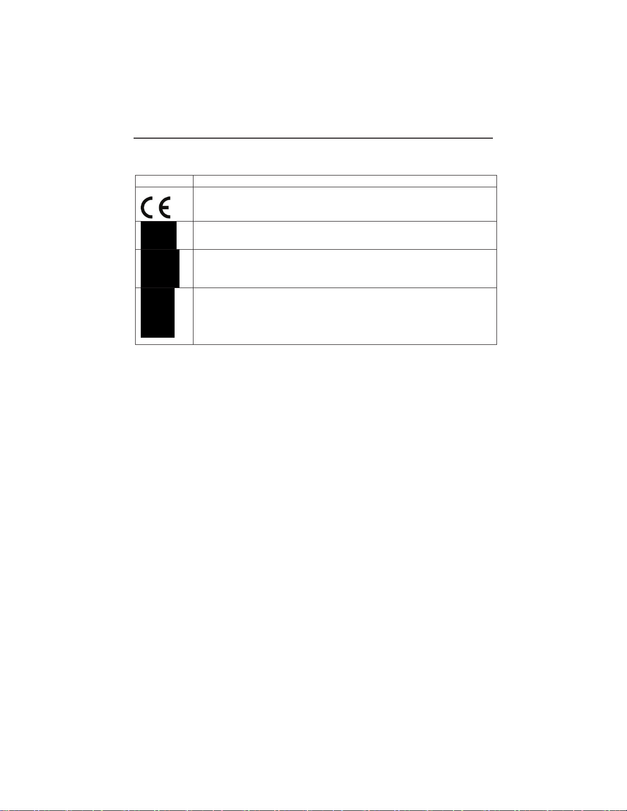
ST400 & ST400M Portable Meter EN-23
Mark
Standard
EN 61326-1
CAN/CSA-C22.2 No. 61010-1
UL Std. No. 61010
5.2 Compliance
This product complies with the EU Directives 2011/65/EU (RoHS), 2014/30/EU
(EMC) and 2014/35/EU (LVD).
-1
This product complies with the EU Directives 2012/19/EU (WEEE) and
2006/66/EC (Batteries). Please dispose of this product in accordance with local
regulations at the collecting point specified for electrical and electronic
equipment.
FCC Note
This equipment has been tested and found to comply with the limits for a Class A digital device,
pursuant to Part 15 of the FCC Rules. These limits are designed to provide reasonable protection
against harmful interference when the equipment is operated in a commercial environment. This
equipment generates, uses, and can radiate radio frequency energy and, if not installed and used
in accordance with the instruction manual, may cause harmful interference to radio
communications. Operation of this equipment in a residential area is likely to cause harmful
interference in which case the user will be required to correct the interference at his own expense
Changes or modifications not expressly approved by the party responsible for compliance could
void the user's authority to operate the equipment.
Industry Canada Note
This Class A digital apparatus complies with Canadian ICES-003.
ISO 9001 Registration
The management system governing the production of this product is ISO 9001:2015 certified.
Find Quality Products Online at: [email protected]
www.GlobalTestSupply.com
Page 27

EN-24 ST400 & ST400M Portable Meter
6 Appendix
6.1 Table 1 BUFFER GROUP
ST400M automatically corrects for the temperature dependence of the buffer group pH value
given in the following tables.
Buffer group 1 US standard
Temp°C pH1.68 pH4.01 pH7.00 pH10.00
5 1.67 4.01 7.09 10.25
10 1.67 4.00 7.06 10.18
15 1.67 4.00 7.04 10.12
20 1.68 4.00 7.02 10.06
25 1.68 4.01 7.00 10.01
30 1.68 4.01 6.99 9.97
35 1.69 4.02 6.98 9.93
40 1.69 4.03 6.97 9.89
45 1.70 4.05 6.97 9.86
50 1.71 4.06 6.96 9.83
Buffer group 2 Europe standard
Temp°C pH2.00 pH4.01 pH7.00 pH9.21 pH11.00
5 2.02 4.01 7.09 9.45 11.72
10 2.01 4.00 7.06 9.38 11.54
15 2.00 4.00 7.04 9.32 11.36
20 2.00 4.00 7.02 9.26 11.18
25 2.00 4.01 7.00 9.21 11.00
30 1.99 4.01 6.99 9.16 10.82
35 1.99 4.02 6.98 9.11 10.64
40 1.98 4.03 6.97 9.06 10.46
45 1.98 4.04 6.97 9.03 10.28
50 1.98 4.06 6.97 8.99 10.10
Buffer group 3 MERCK (Ref. 20°C)
Temp °C pH 2.00 pH4.00 pH7.00 pH9.00 pH12.00
5 2.01 4.04 7.07 9.16 12.41
10 2.01 4.02 7.05 9.11 12.26
15 2.00 4.01 7.02 9.05 12.10
20 2.00 4.00 7.00 9.00 12.00
25 2.00 4.01 6.98 8.95 11.88
30 2.00 4.01 6.98 8.91 11.72
35 2.00 4.01 6.96 8.88 11.67
40 2.00 4.01 6.95 8.85 11.54
45 2.00 4.01 6.95 8.82 11.44
50 2.00 4.00 6.95 8.79 11.33
Buffer group 4 JJG199 (Ref. 25°C)
Find Quality Products Online at: [email protected]
www.GlobalTestSupply.com
Page 28

ST400 & ST400M Portable Meter EN-25
Temp °C 1.680 4.003 6.864 9.182 12460
5 1.669 3.999 6.949 9.391 13.210
10 1.671 3.996 6.921 9.330 13.011
15 1.673 3.996 6.898 9.276 12.820
20 1.676 3.998 6.879 9.226 12.637
25 1.680 4.003 6.864 9.182 12.460
30 1.684 4.010 6.852 9.142 12.292
35 1.688 4.019 6.844 9.105 12.130
40 1.694 4.029 6.838 9.072 11.975
45 1.700 4.042 6.834 9.042 11.828
50 1.706 4.055 6.833 9.015 11.697
Buffer group 5 DIN (19266) (Ref. 25°C)
Temp °C pH1.09 pH4.65 pH6.79 pH9.23 pH12.75
5 1.668 4.004 6.950 9.392 13.207
10 1.670 4.001 6.922 9.331 13.003
15 1.672 4.001 6.900 9.277 12.810
20 1.676 4.003 6.880 9.228 12.627
25 1.680 4.008 6.865 9.184 12.454
30 1.685 4.015 6.853 9.144 12.289
35 1.691 4.026 6.845 9.110 12.133
40 1.697 4.036 6.837 9.076 11.984
45 1.704 4.049 6.834 9.046 11.841
50 1.712 4.064 6.833 9.018 11.705
Buffer group 6 DIN (19267) (Ref. 25°C)
Temp °C pH1.09 pH4.65 pH6.79 pH9.23 pH12.75
5 1.08 4.67 6.87 9.43 13.63
10 1.09 4.66 6.84 9.37 13.37
15 1.09 4.66 6.82 9.32 13.16
20 1.09 4.65 6.80 9.27 12.96
25 1.09 4.65 6.79 9.23 12.75
30 1.10 4.65 6.78 9.18 12.61
35 1.10 4.65 6.77 9.13 12.45
40 1.10 4.66 6.76 9.09 12.29
45 1.10 4.67 6.76 9.04 12.09
50 1.11 4.68 6.76 9.00 11.98
Find Quality Products Online at: [email protected]
www.GlobalTestSupply.com
Page 29

EN-26 ST400 & ST400M Portable Meter
Substance at 25 °C
Concentration [%]
Temperature coefficient α [%/°C]
HCl101.56
KCl101.88
CH3COOH
10
1.69
NaCl102.14
H2SO4
10
1.28
HF
1.5
7.20
Standard
Measurement
temp.: 15°C
Measurement
temp.: 20°C
Measurement
temp.: 25°C
Measurement
temp.: 30°C
84 μS/cm
1.95
1.95
1.95
2.01
1413 μS/cm
1.94
1.94
1.94
1.99
12.88 mS/cm
1.90
1.89
1.91
1.95
6.2 Table 2 Examples of temperature coefficients (α-value)
α-coefficients of conductivity standards for a calculation to a reference temperature of 25°C
Find Quality Products Online at: [email protected]
www.GlobalTestSupply.com
Page 30

ST400 & ST400M Portable Meter EN-27
T(°C)
10 μS/cm
84 μS/cm
500μS/cm
1413μS/cm
12.88 mS/cm
5
6.1 μS/cm
53 μS/cm
315.3μS/cm
896 μS/cm
8.22 mS/cm
10
7.1 μS/cm
60 μS/cm
359.63μS/cm
1020 μS/cm
9.33 mS/cm
15
8.0 μS/cm
68 μS/cm
402.93μS/cm
1147 μS/cm
10.48 mS/cm
20
9.0 μS/cm
76 μS/cm
451.53μS/cm
1278 μS/cm
11.67 mS/cm
25
10.0 μS/cm
84 μS/cm
500.03μS/cm
1413 μS/cm
12.88 mS/cm
30
11.0 μS/cm
92 μS/cm
548.5μS/cm
1552 μS/cm
14.12 mS/cm
35
12.1 μS/cm
101 μS/cm
602.53μS/cm
1667 μS/cm
15.39m
Conductivity
At 25
°C
TDS
KCl
TDS
NaCl
ppm value
Factor
ppm value
Factor
84 μS
40.38
0.5048
38.04
0.4755
447 μS
225.6
0.5047
215.5
0.4822
1413 μS
744.7
0.527
702.1
0.4969
1500 μS
757.1
0.5047
737.1
0.4914
8974 μS
5101
0.5685
4487
0.5000
12.88 μS
7447
0.5782
7230
0.5613
15 μS
8759
0.5839
8532
0.5688
80 mS
52.168
0.6521
48.384
0.6048
6.3 Table 3 Conductivity standards
S/cm
Ohaus products are warranted against defects in materials and workmanship from the date of
LIMITED WARRANTY
delivery through the duration of the warranty period. During the warranty period Ohaus will repair,
or, at its option, replace any component(s) that proves to be defective at no charge, provided that
the product is returned, freight prepaid, to Ohaus.
This warranty does not apply if the product has been d amaged by accident or misuse, exposed to
radioactive or corrosive materials, has foreign material penetrating to the inside of the product, or
as a result of service or modification by other than Ohaus. In lieu of a properly returned warranty
registration card, the warranty period shall begin on the date of shipment to the authorized dealer.
No other express or implied warranty is given by Ohaus Corporation. Ohaus Corporation shall not
be liable for any consequential damages.
As warranty legislation differs from state to state and country to country, please contact Ohaus or
your local Ohaus dealer for further details.
Find Quality Products Online at: [email protected]
www.GlobalTestSupply.com
 Loading...