

Page 1

ST ARTER 5000 Bench pH Meter EN-11
STARTER 3100C
Bench Conductivity Meter
Instruction Manual
Manual de instrucciones del
Conductivímetro de mesa
STARTER 3100C
STARTER 3100C
Appareil de mesure de la
conductivité de laboratoire
Manuel d’instructions
STARTER 3100C
Medidor de Condutividade de
Bancada
Manual de Instruções
Find Quality Products Online at: [email protected]
www.GlobalTestSupply.com
Page 2

TABLE OF CONTENTS
INTRODUCTION ................................................................... 1
1
1.1 Definition of Signal Warnings and Symbols ...................................... 1
1.2 Safety Precautions ............................................................................ 2
1.3 Display and controls .......................................................................... 3
2 INSTALLATION ..................................................................... 5
2.1 Package contents .............................................................................. 5
2.2 Installing the stand-alone electrode holder ....................................... 6
2.3 Installing the power adapter .............................................................. 6
2.4 Connect the conductivity electrode ................................................... 7
2.5 Meter stand for adjusting view angle ................................................. 7
2.6 Attached quick guide ......................................................................... 7
3 SETUP ................................................................................... 8
3.1 Set temperature unit .......................................................................... 8
3.2 Set MTC temperature value .............................................................. 8
3.3 Set calibration standard .................................................................... 8
3.4 Set temperature correction coefficient .............................................. 8
3.5 Set TDS factor ................................................................................... 9
4 STARTER 3100C OPERATION .......................................... 10
4.1 Calibration ....................................................................................... 10
4.1.1 Selecting a standard ................................................................. 10
4.1.2 Performing a calibration ........................................................... 10
4.2 Sample measurement ...................................................................... 11
4.3 TDS and Salinity measurement ....................................................... 11
4.4 Using the memory ............................................................................ 11
4.4.1 Storing a reading ....................................................................... 11
4.4.2 Recalling from memory ............................................................ 12
4.4.3 Clearing the memory ................................................................ 12
4.5 Printing ............................................................................................ 12
5 MAINTENANCE .................................................................. 14
5.1 Error message ................................................................................. 14
5.2 Meter maintenance.......................................................................... 14
5.3 Self diagnosis .................................................................................. 14
5.4 Recover Factory Setup ................................................................... 15
6 TECHNICAL DATA .............................................................. 16
6.1 Specifications .................................................................................. 16
6.2 Compliance ..................................................................................... 17
7 APPENDIX .......................................................................... 18
7.1 Conductivity standards .................................................................... 18
7.2 Examples of temperature coefficients (α-value).............................. 18
7.3 Conductivity to TDS conversion factors .......................................... 18
Find Quality Products Online at: [email protected]
www.GlobalTestSupply.com
Page 3
STARTER 3100C Bench Conductivity Meter EN-1
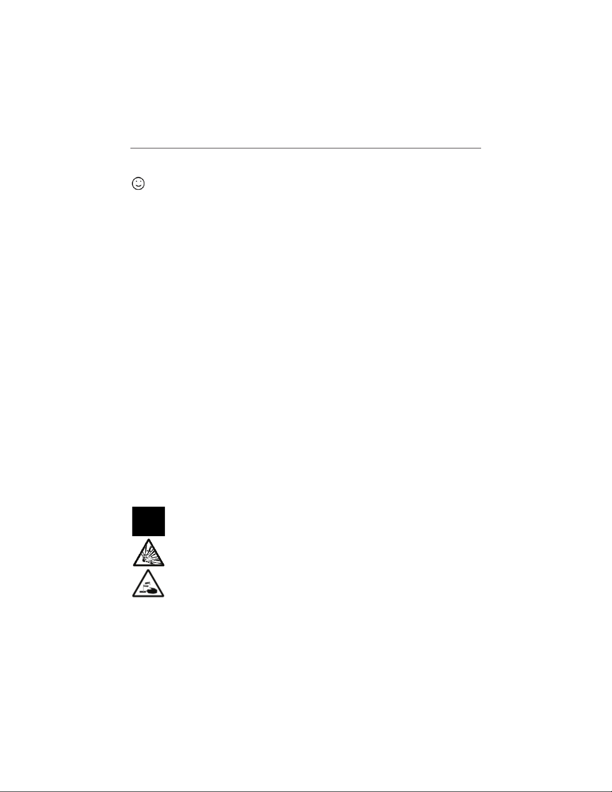
General hazard
Explosion hazard
Corrosive hazard
±
Alternating current
¯
Direct curren t
1 INTRODUCTION
Thank you for choosing OHAUS. Please read the manual completely before using the
STARTER 3100C bench conductivity meter to avoid incorrect operation.
The STARTER 3100C has an excellent performance/price ratio and is designed with many useful
features.
Starter 3100C offers many practical features such as:
x Backlight liquid crystal screen which make the display more clearly
x Auto/manual endpoint
x Quick Guide attached under meter to assist with operation
x RS232 port and memory to store up to 99 measurements
1.1 Definition of Signal Warnings and Symbols
Safety notes are marked with signal words and warning symbols. These show safety issues and
warnings. Ignoring the safety notes may lead to personal injury, damage to the instrument,
malfunctions and false results.
Signal Words
WARNING For a hazardous situation with medium risk, possibly resulting in
CAUTION For a hazardous situation with low risk, resulting in damage to the
Attention For important information about the product.
Note For useful information about the product
Warning Symbols
injuries or death if not avoided.
device or the property or in loss of data, or injuries if not avoided.
Find Quality Products Online at: [email protected]
www.GlobalTestSupply.com
Page 4

EN-2 STA RTER 3100C Bench Conductivity Meter
1.2 Safety Precautions
CAUTION: Read all safety warnings before installing, making connections, or servicing this
equipment. Failure to comply with these warnings could result in personal injury and/or property
damage. Retain all instructions for future reference.
x Verify that the input voltage range printed on the data label and the plug type matches the
local AC power to be used.
x Make sure that the power cord does not pose a potential obstacle or tripping hazard.
x Use the equipment only in dry locations.
x Dry off any liquid spills immediately. The instrument is not watertight.
x When using chemicals and solvents, comply with the instructions of the chemical producer
and the general lab safety rules.
x Use only approved accessories and peripherals.
x Operate the equipment only under ambient conditions specified in these instructions.
x Disconnect the equipment from the power supply when cleaning.
x Do not operate the equipment in hazardous or unstable environments.
x Service should only be performed by authorized personnel.
Find Quality Products Online at: [email protected]
www.GlobalTestSupply.com
Page 5
ST ARTER 3100C Bench Conductivity Meter EN-3
1
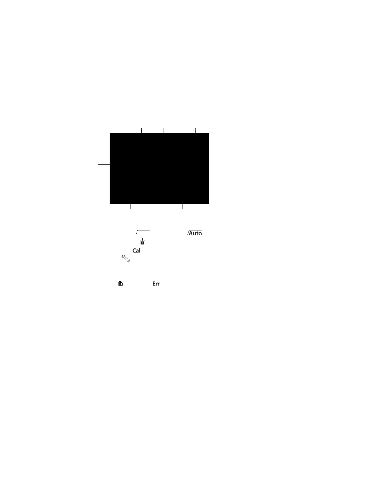
Endpoint stability / Auto endpoint
2
Measurement icon - measurement or calibration is running
3
Calibration icon - calibration in progress
4
Setup icon - instrument is in the setup mode
5
TDS factor in the setup mode
6
Conductivity / TDS / Salinity / Cell Constant
7
Standard / Error index
8
Temperature during measurement or reference temperature in setup mode
1 2 3
4
5
7
8
6
1.3 Display and controls
Displays
Find Quality Products Online at: [email protected]
www.GlobalTestSupply.com
Page 6
EN-4 STARTER 3100C Bench Conductivity Meter
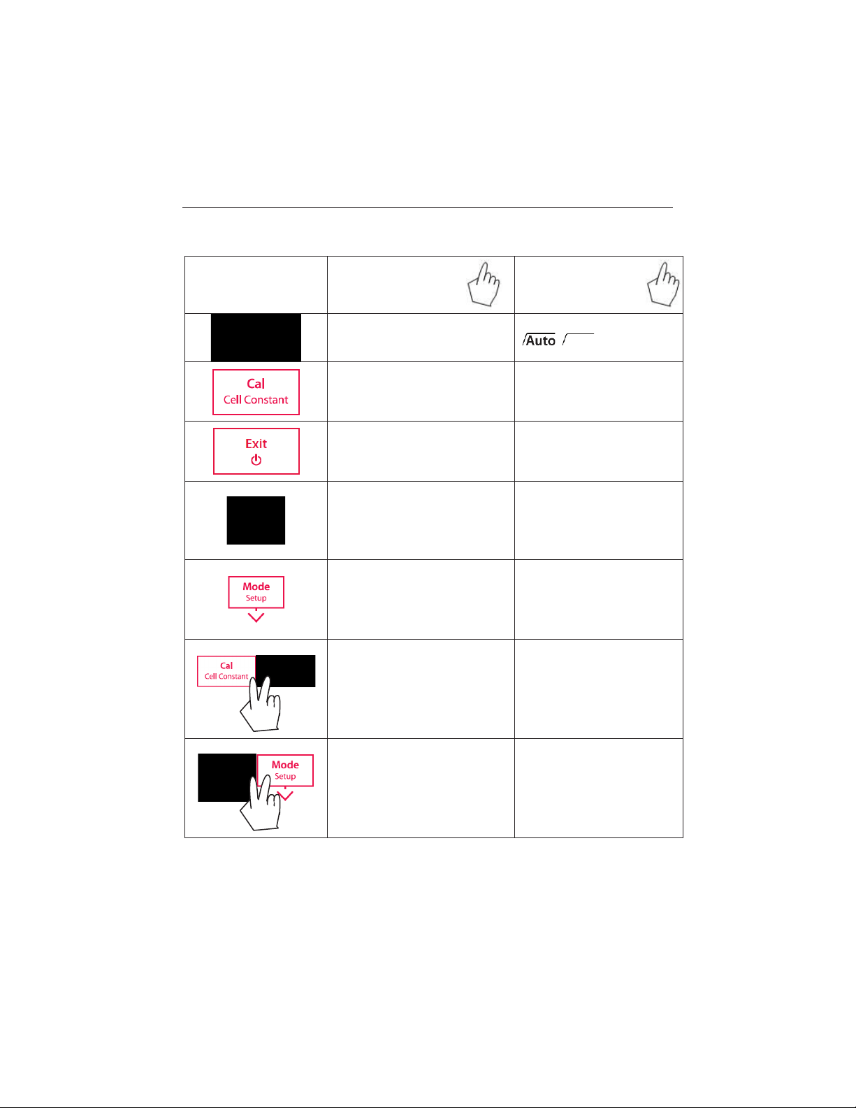
Button
Press & release
Press & hold
for 3 seconds
- Start or endpoint measurement
- Confirm setting, store entered
value
- Turn auto endpoint on / off
- Start calibration
- Review the latest calibration
- Meter turn on
-
to measurement screen
- Meter turn off
- Store current reading to memory
-
-
- Recall stored data
-
- Switch between pH and mV
measu ring mo des
-
Decrease value during setting
- Scroll down through the memory
- Enter setup mode
-
Turn on/off the backlight of the
LCD
Controls
,
data (cell constant)
Return
Increase value during setting
Scroll up through the memory
Start self-diagnosis
Print current memory data
Find Quality Products Online at: [email protected]
www.GlobalTestSupply.com
Page 7
ST ARTER 3100C Bench Conductivity Meter EN-5
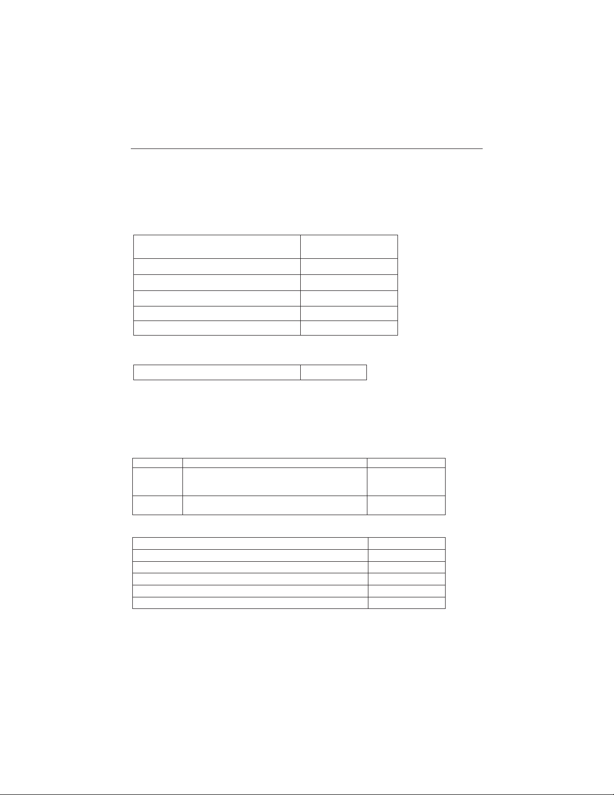
Model
Description
P/N
STCON3
4-ring cond. electrode
(70 μS/cm
( 2-70 μS/cm, 1-5% accuracy)
83033972
STCON7
Pure water cond. electrode
(0.02μS/cm-200 μS /cm; 0.02 μS/cm accuracy)
30080693
Standard Conduct 10 μS/cm 250ml
30100441
Standard Conduct 84 μS/cm 250ml
30100442
Standard Conduct 1413 μS/cm 250ml
30100443
Standard Conduct12.88mS/cm 250ml
30100444
Electrode holder stand alone (3100/3100C)
30058733
In use cover
30058734
ST
3100C-B
U
nits
STARTER 3100C meter
1
Stand alone electrode holder
1
1413 μS/cm standard solution
1 bottle (about 20ml)
12.88 mS/cm standard solution
1 bottle (about 20ml)
In use cover
1
STCON3 conductivity electrode
1
2 INSTALLATION
Carefully unpack the meter.
2.1 Package contents
The ST3100C-B package has the following items
In addition to ST3100C-B content, the ST3100C-F package also includes the following:
The best measurement range for STCON3 4-ring (4-pole) conductivity elect rode is 70 μS/cm-200
mS/cm. In this range the measurement accuracy can reach 0.5%.
If you use STCON3 to measure pure water in which conductivity value is below 70 μS/cm; the
measurement will be less accurate (approximately 1% to 5%).
Does not use STCON3 to measure cond. value less than 2 μS/cm, the accuracy is not good.
Accessories:
-200mS/cm, 0.5% accuracy; )
Find Quality Products Online at: [email protected]
www.GlobalTestSupply.com
Page 8

EN-6 STARTER 3100C Bench Conductivity Meter
2.2 Installing the stand-alone electrode holder
Install the electrode arm on the base,
After adjusting the tension knob to some extent, you can move up and down. When the
electrode is installed on the arm, the storage bottle of pH electrode fits into the base hole.
2.3 Installing the power adapter
Insert the right adapter clip into the power adapter slot.
The Ohaus balance power supply is also 12V which could be used for the pH meter.
Find Quality Products Online at: [email protected]
www.GlobalTestSupply.com
Page 9
ST ARTER 3100C Bench Conductivity Meter EN-7
2.4 Connect the conductivity electrode
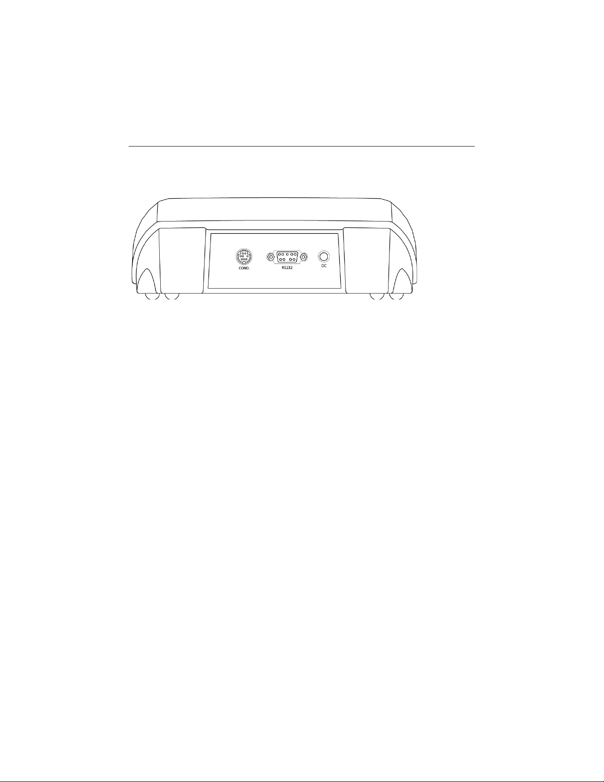
There is one socket “COND.” for conductivity electrode.
2.5 Meter stand for adjusting view angle
One unique design of the STARTER 3100C is the meter stand, which can be used to adjust the view
angle of the display in case of working on high lab table.
2.6 Attached quick guide
Another unique design of the STARTER 3100C is the attached quick guide, the quick guide is
attached into the bottom housing of the meter, you can use finger to pull it out.
Find Quality Products Online at: [email protected]
www.GlobalTestSupply.com
Page 10
EN-8 STARTER 3100C Bench Cond uc t ivity Meter
3 SETUP
3.1 Set temperature unit
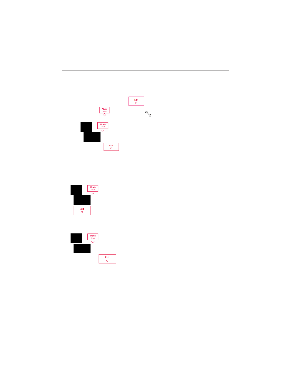
x Power the meter on by pressing .
x Press and hold until the set up icon appears on the display and the current
temperature unit blinks. (°C or °F)
x Use
x Press
following or press
Note: °C = 5/9 (°F -32)
or butt ons to select temperature unit .
to confirm your setting. Continue with temperature value setting by
to go back to the measurement screen.
3.2 Set MTC temperature value
After the temperature unit setting, the meter goes to setup manual temperature (MTC) value
setting.
Use
Press
press
or buttons to adjust the temperature value.
to confirm your setting. Continue with calibration standard setting by following or
to go back to the measurement screen.
3.3 Set calibration standard
After the MTC temperature value setting, the meter goes to setup calibration standard.
Use
Press
by following or press
or buttons to select calibration standard.
to confirm your setting. Continue with temperature correction coefficient setting
to go back to the measurement screen.
3.4 Set temperature correction coefficient
After the calibration standard setting, the meter goes to the temperature correction coefficient
setting.
Find Quality Products Online at: [email protected]
www.GlobalTestSupply.com
Page 11
STARTER 3100C Bench Conductivity Meter EN-9
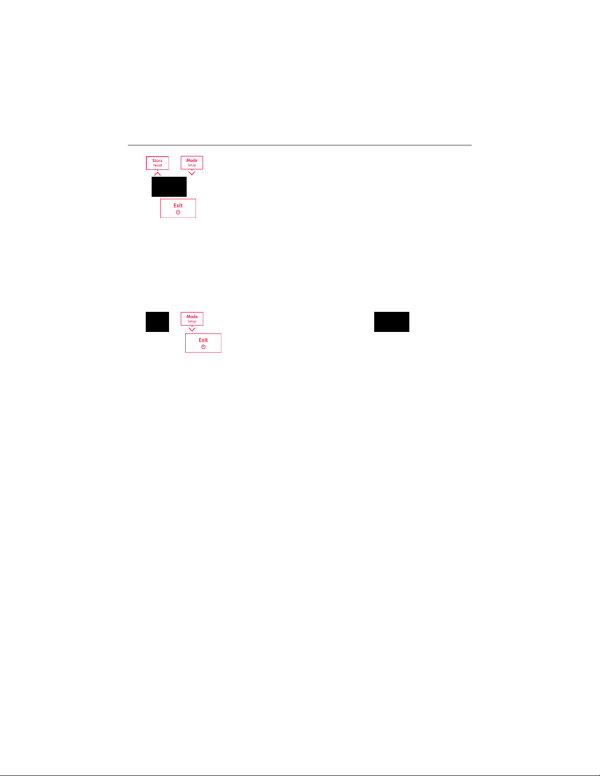
Use
Press
or press
Note:
If you set the temperature correction coefficient value as 0 %/°C , that means NO Temperature
Compensation for the conductivity measurem ent. The meter displays the real conductivity value
at current temperature.
or buttons to adjust the temperature correction value. (0.00 to 10.00 %/°C).
to confirm your setting. Continue with reference temperature setting by following
to go back to the measurement screen.
3.5 Set TDS factor
After selecting the reference temperature, the current TDS factor blinks.
Use
setting or press
or buttons to adjust the TDS factor value. Press to confirm your
to go back to the measurement screen.
Find Quality Products Online at: [email protected]
www.GlobalTestSupply.com
Page 12
EN-10 STARTER 3100C Bench Conduc t ivity Meter
10 μS/cm
84 μS/cm
1413 μS/cm
12.88 mS/cm
4 STARTER 3100C OPERATION
The first time you use the conductivity electrode, it should be calibrated before taking any
measurement. Please also read the conductivity electrode instruction manual for reference.
4.1 Calibration
4.1.1 Selecting a standard
When using the STARTER 3100C conductivity meter, you have to select a st andard for calibration
(see 3.3).
WARNING Do not operate the equipment in hazardous environments. The
equipment is not explosion protected.
WARNING When using chemicals and solvents, comply with the instructions of the
chemical producer and the general lab safety rules.
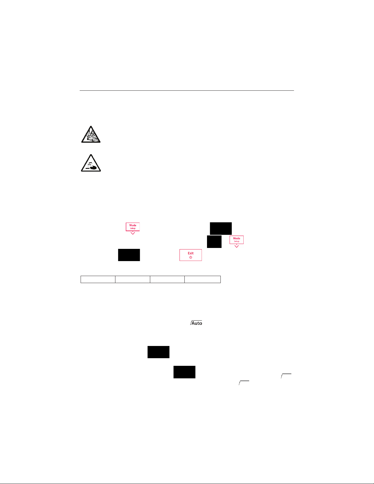
Press and hold the
unit and value. Then the current standard blinks. Use
standards, press
The 4 predefined standards are:
Tables for automatic temperature compensation are programmed in the meter for each standard
(see appendix).
enter setup mode, after press to confirm the temperature
or buttons to select the
to confirm. Press to leave the setup mode.
4.1.2 Performing a calibration
When performing calibration, Ohaus recommends using Auto End Point Mode. After powering
the meter on, be sure the top of the screen shows
Mode.
Auto or Manual End point Mode:
o Press and hold to change the End Point Mode.
o When in Manual Mode, to manually reach a pH measurement or calibration value,
you need to press buttonthen the sample reading or calibration value freezes,
freezes on the display.
to ensure the meter is in Auto End point
when reading is stable and displays :
blinks 3 times and
Find Quality Products Online at: [email protected]
www.GlobalTestSupply.com
Page 13
STARTER 3100C Bench Conductivity Meter EN-11
o When in Auto End Point Mode, the meter determines when the reading is stable
then displays and locks the reading or calibration value automatically, the reading
freezes and
on the display.
Place the conductivity sensor in the selected calibration standard, wait 10-15s, then press
.
The calibration icon
blinking during calibration measurement. The meter reaches endpoint automatically according to
the preselected auto-endpoint mode after the signal has stabilized.
When the calibration is finished, the standard value is displayed and stored; the measurement
icon
blinks 3 times and disappears.
blinks 3 times then disappears; blinks 3 times and freezes
and the measurement icon appear on the display. The icon is
To finish the calibration and return to the sample measurement, press
constant is then shown on the display for 3 seconds.
Note:
To ensure the most accurate conduct ivity readings, you should verify your cell constant with a
standard solution before measurement and recalibrate if necessary. Always use fresh standards.
For STCON3 the normal cell constant range is 1.50 – 2.00. (e.g. 1.71 /cm) if the cell constant is
outside the range due to an improper calibration, you may need to recover factory settings (see
5.4), then repeat calibration.
. The cell
4.2 Sample measurement
Place the conductivity sensor in the sample, wait 10-15s, then press to start the
measurement. The measurement icon
blinking during measurement and the display shows the conductivity of the sample.
When it reaches endpoint (auto endpoint or manual endpoint), you can record the result.
Stability criterion for conductivity measurement: The sensor input signal of the meter may not
change by more than 0.4% from the measured average conductivity of the probe in 6 seconds.
appears on the display. The measurement icon is
4.3 TDS and Salinity measurement
To perform a TDS or salinity measurement, follow the same procedure as for a conductivity
measurement. Press
to switch between conductivity and TDS measurement mode.
Find Quality Products Online at: [email protected]
www.GlobalTestSupply.com
Page 14

EN-12 STARTER 3100C Bench Conduc t ivity Meter
4.4 Using the memory
4.4.1 Storing a reading
The STARTER 3100C can store up to 99 endpoint results.
Press
been stored.
If you press
further data you will have to clear the memory. (See 3.4.3)
when the measurement reaches endpoint. M01 indicates that one result has
when M99 is displayed, FUL displays to indicate the memory is full. To store
4.4.2 Recalling from memory
Press and hold to recall the stored values from memory when the current
measurement reaches endpoint.
Press
is being displayed.
Press
or to scroll through the stored results. R01 to R99 indicates which result
to exit.
4.4.3 Clearing the memory
Pressing or to scroll through the stored results until “MRCL” appears.
Press
Now we can two choices:
Press
Press
, CLr blinks;
to confirm the deletion of all the stored data.
to return to the measurement mode without deleting the memory.
4.5 Printing
If a printer (e.g. SF-F40A) is connected to the STARTER 3100C, a print-out is automatically
generated after each end pointed measurement or calibration. (printer baud rate 9600bps; 8 dat a
bit; none parity bit; 1 stop bit)
The format for the print-out following a Cond. measurement is:
End Point, Value, Temp., ATC/MTC
Auto EP, 68.8μS/cm, 26.8°C , ATC
Ref.25°C , T.Comp.Coeff. 2.00%/°C
Find Quality Products Online at: [email protected]
www.GlobalTestSupply.com
Page 15

STARTER 3100C Bench Conductivity Meter EN-13
The details for the second line are:
Auto EP, 85.1μS/cm, 26.8°C, ATC
| | | |---- Auto Temp. Compensation
| | |----------------Temperature value and unit
| |------------------------- Conduct i vity value
|---------------------------------------- Auto End Point
The details for the third line are:
Ref.25°C , T.Comp.Coeff. 2.00%/°C
| |
| |---------------- Temperature com pensation coefficient value
|------------------------------------------- Reference temperature, 20 or 25 °C
The format for the print-out following a TDS measurement is:
End Point, Value, Temp., ATC/MTC
Manual EP, 38.0mg/L, 23.2°C , ATC
Ref.25°C , T.Comp.Coeff. 2.00%/°C
TDS-F 0.5
The format for the print-out following a Salinity measurement is:
End Point, Value, Temp., ATC/MTC
Manual EP, 0.08psu, 25.0°C , MTC
The print-out in case of an error message is:
End Point, Value, Temp., ATC/MTC
Error4
The print-out for a successful calibration is:
Standard: 1413μS/cm
Temperature: 30.0 °C
Calibration value: 1552μS/cm
Cell Constant: 1.66 cm-1
ATC/MTC: ATC
Printing from memory When scrolling through the memory you can print the entry that is currently
viewed by pressing and holding
Recall 08:
EndPoint, Value, Temp., ATC/MTC
Auto EP, 68.8μS/cm, 26.8°C , ATC
Ref.25°C , T.Comp.Coeff. 2.00%/°C
for 2 seconds. The printout format is followings:
Find Quality Products Online at: [email protected]
www.GlobalTestSupply.com
Page 16
EN-14 STARTER 3100C Bench Co nd uctivity Meter
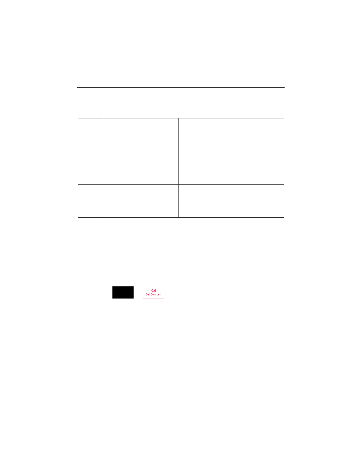
Error 0
Memory access error
Reset to factory settings
Error 1
Self-diagnosis failed
Repeat the self-diagnosis procedure and make
sure that you finish pressing all five keys within
two minutes.
Error 2
Measured values out of range
C:
TDS: < 0.1 mg/L or > 199.9 g/L
SAL: > 100.0 ps u
Make if the electrode is properly connected
an
Error 3
Measured standard temperature
out of range (5 ... 35 °C)
Keep the standard temperature within the
range for calibration
Error 4
Measuring temperature out of
range (0 ... 100
Check if the electrode is properly connected
and keep the sample temperature within the
range
Error 9
The current data set has already
been stored once
An endpoint reading can only be stored once.
Perform a new measurement to store.
b
5 MAINTENANCE
5.1 Error message
> 199.9 mS/cm
°C)
If there is an error, the meter will beep 3 times to alert.
d placed in the sample solution
5.2 Meter maintenance
Never unscrew the two halves of the housing!
The STARTER 3100C does not require any maintenance. To clean, use a damp cloth.
The housing is made of acrylonitrile butadiene styrene (ABS). This material is susceptible to
damage by some organic solvents, such as toluene, xylene and methyl ethyl ketone (MEK). Any
spillage should be immediately wiped off.
5.3 Self diagnosis
Press and hold and simultaneously until the meter displays the full screen.
Each icon blinks one after the other. This way you may check whether all icons are correctly
shown. The next step is to check that the keys are functioning correctly. This requires user
interaction.
When b
blinks, five icons are displayed. Press the 6 keys in any order. Each time you press a key
an icon disappears from the screen, continue to press the other keys until all the icons have
disappeared.
When the self-diagnosis has been completed successfully, PAS appears. If self-diagnosis fails,
error message Err 1 appears .
Find Quality Products Online at: [email protected]
www.GlobalTestSupply.com
Page 17
STARTER 3100C Bench Conductivity Meter EN-15
Note:
You have to finish pressing all five keys within two minutes, otherwise Err 1 appears and you will
have to repeat the procedure.
5.4 Recover Factory Setup
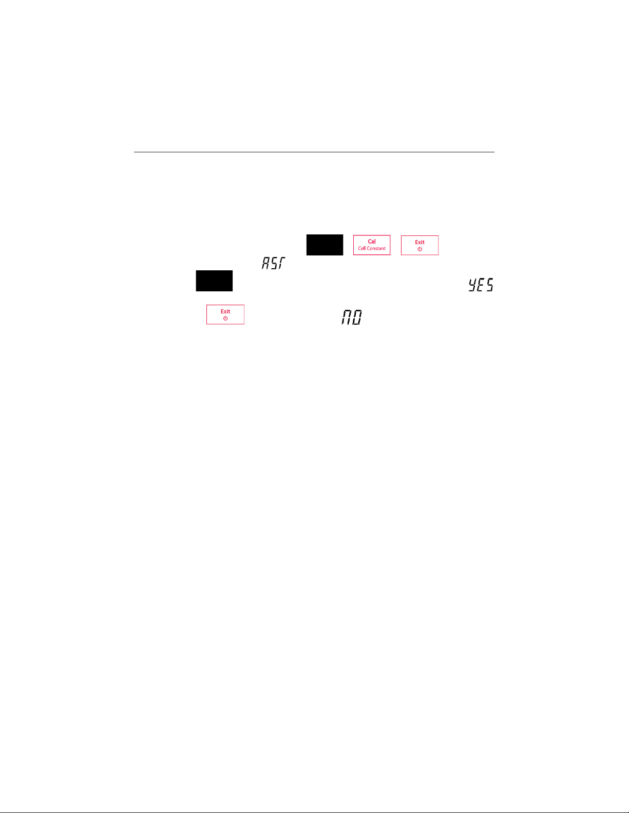
When the meter is off , press and hold & & together for 3
seconds, the screen displays
and blinks, means “Reset”. Then we have 2 choice:
Press
then restart the meter.
Or press
to reset factory settings (MTC, slope and offset, etc.), display
to quit the setting, display then turn off the meter.
Find Quality Products Online at: [email protected]
www.GlobalTestSupply.com
Page 18

EN-16 STARTER 3100C Bench Conductivity Meter
Model
ST3100C
Measuring range
0.0 μS/cm…199.9 mS/cm
0.1 mg/l…199.9 g/l (TDS)
0.00 ...
0 °C…100 °C
Resolution
Automatic range
0.1 °C
Error limits/Accuracy
± 0.5 % of the measured value
± 0.3 °C
Calibration
1 point
4 predefined standards
Memory
99 measurements
The last calibration data
Power supply
AC Adapter Input: 100-240V ~ X.XA 50/60 Hz
AC Adapter Output: 12V ¯ X.XA
Size/weight
220 W x 175 D x 78 H mm / 0.75 kg
Display
White backlit Liquid crystal
Input
Mini-Din
Temperature-compensation
Linear: 0.00 %/°C…10.00 %/°C
Reference temperature: 20 & 25 °C
Housing
ABS
6 TECHNICAL DATA
6.1 Specifications
Ambient conditions
x Indoor use only
x Altitude: Up to 2000 m
x Specified Temperature range: 5°C to 40°C
x Hum idity: maximum relative humidity 80 % for temperatures up to 30°C decreasing linearly to
50% relative humidity at 40°C
x Mains supply voltage fluctuations: up to ±10% of the nominal voltage
x Installation category II
x Pollution degree: 2
x Operability is assured at ambient temperatures between 5°C to 40°C
100.0 psu (Salinity)
Find Quality Products Online at: [email protected]
www.GlobalTestSupply.com
Page 19
STARTER 3100C Bench Conductivity Meter EN-17
6.2 Compliance
This product conforms to the EMC Directive 2004/108/EC and the Low Voltage
Directive 2006/95/EC.
In conformance with the European Directive 2002/96/EC on Waste Electrical
and Electronic Equipment (WEEE) this device may not be disposed of in
domestic waste. This also applies to countries outside the EU, per their specific
requirements. Please dispose of this product in accordance with local
regulations at the collecting point specified for electrical and electronic
equipment. If you have any questions, please contact the responsible authority
or the distributor from which you purchased this device. Should this device be
passed on to other parties (for private or professional use), the content of this
regulation must also be related.Thank you for your contribution to
environmental protection.
FCC Note: This equipment has been tested and found to comply with the limits for a Class
A digital device, pursuant to part 15 of the FCC Rules. These limits are designed to provide
reasonable protection against harmful interference when the equipment is operated in a
commercial environment. This equipment generates, uses, and can radiate radio frequency
energy and, if not installed and used in accordance with the instruction manual, may cause
harmful interference to radio communications. Operation of this equipment in a residential
area is likely to cause harmful interference in which case the user will be required to correct
the interference at his own expense.
ISO 9001 Registration
In 1994, OHAUS Corporation, USA, was awarded a certificate of registration to ISO 9001 by
Bureau Veritus Quality International (BVQI), confirming that the OHAUS quality
management system is compliant with the ISO 9001 standards requirements. On June 21,
2012, OHAUS Corporation, USA, was re-registered to the ISO 9001:2008 standard.
Find Quality Products Online at: [email protected]
www.GlobalTestSupply.com
Page 20
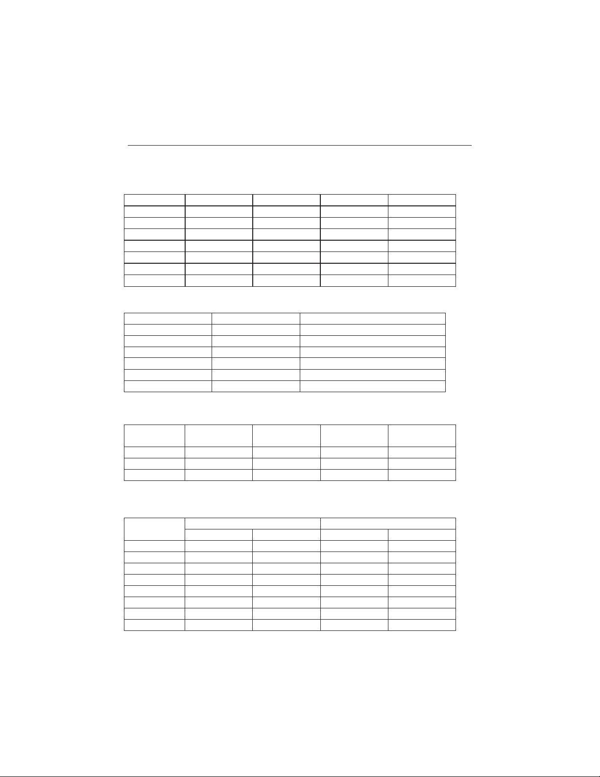
EN-18 STARTER 3100C Bench Co nd uctivity Meter
T(°C)
10 μS/cm
84 μS/cm
1413 μS/cm
12.88 mS/cm
5
6.1 μS/cm
53 μS/cm
896 μS/cm
8.22 mS/cm
10
7.0 μS/cm
60 μS/cm
1020 μS/cm
9.33 mS/cm
15
8.0 μS/cm
68 μS/cm
1147 μS/cm
10.48 mS/cm
20
9.0 μS/cm
76 μS/cm
1278 μS/cm
11.67 mS/cm
25
10.0 μS/cm
84 μS/cm
1413 μS/cm
12.88 mS/cm
30
11.0 μS/cm
92 μS/cm
1552 μS/cm
14.12 mS/cm
35
12.1 μS/cm
101 μS/cm
1667 μS/cm
15.39 mS/cm
Substance at 25 °C
Concentration [%]
Temperature coefficient α [%/°C]
HCl
10
1.56
KCl
10
1.88
CH3COOH
10
1.69
NaCl
10
2.14
H2SO4
10
1.28
HF
1.5
7.20
Standard
Measurement
temp.: 15°C
Measurement
temp.: 20°C
Measurement
temp.: 30°C
Measurement
temp.: 35°C
84 μS/cm
1.95
1.95
1.95
2.01
1413 μS/cm
1.94
1.94
1.94
1.99
12.88 mS/cm
1.90
1.89
1.91
1.95
Conductivity
At 25 °C
TDS KCl
TDS NaCl
ppm value
Factor
ppm value
Factor
84 μS
40.38
0.5048
38.04
0.4755
447 μS
225.6
0.5047
215.5
0.4822
1413 μS
744.7
0.527
702.1
0.4969
1500 μS
757.1
0.5047
737.1
0.4914
8974 μS
5101
0.5685
4487
0.5000
12.88 μS
7447
0.5782
7230
0.5613
15 μS
8759
0.5839
8532
0.5688
80 mS
52.168
0.6521
48.384
0.6048
7 APPENDIX
7.1 Conductivity standards
7.2 Examples of temperature coefficients (α-value)
α-coefficients of conductivity standards for a calculation to reference temperature of 25°C
7.3 Conductivity to TDS conversion factors
Find Quality Products Online at: [email protected]
www.GlobalTestSupply.com
Page 21

STARTER 3100C Bench Conductivity Meter EN-19
LIMITED WARRANTY
Ohaus products are warranted against defects in materials and workmanship from the date of
delivery through the duration of the warranty period. During the warrant y period Ohaus will repair,
or, at its option, replace any component(s) that proves to be defective at no charge, provided that
the product is returned, freight prepaid, to Ohaus.
This warranty does not apply if the product has been damaged by accident or misuse, exposed to
radioactive or corrosive materials, has foreign m aterial penetrating to the inside of the product, or
as a result of service or modification by other than Ohaus. In lieu of a properly returned warranty
registration card, the warranty period shall begin on the dat e of shipment to the authorized dealer.
No other express or implied warranty is given by Ohaus Corporation. Ohaus Corporation shall not
be liable for any consequential damages.
As warranty legislation differs from state to state and country to country, please contact Ohaus or
your local Ohaus dealer for further details.
Find Quality Products Online at: [email protected]
www.GlobalTestSupply.com
 Loading...