

Page 1
Ranger RP Compact Scales
Instruction Manual
Page 2

@@@@@
Page 3

Table of contentsRanger RP
Table of contents
Page
1 Introduction .....................................................................................5
1.1 Safety instructions .............................................................................5
1.2 Description ......................................................................................6
1.3 Putting into operation ......................................................................10
2 Operation ......................................................................................12
2.1 Switching on and off .......................................................................12
2.2 Zeroing / Zero point correction ..........................................................12
2.3 Simple weighing .............................................................................12
2.4 Weighing with tare ..........................................................................13
2.5 Displaying the capacity available ......................................................15
2.6 Dynamic weighing ..........................................................................15
2.7 Weighing-in to a target weight and checkweighing .............................16
2.8 Working with identifications .............................................................18
2.9 Printing results ...............................................................................18
2.10 Displaying info ...............................................................................19
2.11 Switching scales .............................................................................19
2.12 Totalising .......................................................................................20
2.13 Cleaning ........................................................................................21
3 Counting .......................................................................................22
3.1 Counting parts into a container .........................................................22
3.2 Counting parts out of a container ......................................................23
3.3 Counting with variable reference quantity ...........................................23
3.4 Counting with minimum accuracy ....................................................23
3.5 Reference optimization ....................................................................24
3.6 Counting with automatic reference determination ................................24
3.7 Counting with a known average piece weight ....................................24
3.8 Counting by calling up a saved average piece weight .........................25
3.9 Counting by calling up a saved target quantity ...................................26
3.10 Counting with two scales .................................................................27
4 Settings in the menu ......................................................................29
4.1 Operating the menu ........................................................................29
4.2 Overview .......................................................................................31
4.3 Scale settings (SCALE) ....................................................................34
4.4 Application settings (APPLICATION) ..................................................37
4.5 Terminal settings (TERMINAL) ..........................................................41
4.6 Configuring interfaces (COMMUNICATION) .........................................42
4.7 Diagnosis and printing out of the menu settings (DIAGNOS) ................46
5 Interface description ......................................................................48
5.1 OHAUS interface commands ............................................................48
5.1 SICS interface commands ................................................................50
5.2 TOLEDO Continuous mode ..............................................................53
3
Page 4

Table
of contents
Ranger RP
6 Event and error messages .............................................................. 55
7 Technical data and accessories ...................................................... 57
7.1 Technical data ............................................................................... 57
7.2 Accessories ................................................................................... 63
8 Appendix ...................................................................................... 64
8.1 Information for certified scales in EC countries ................................... 64
2 Safety checks ................................................................................. 64
8.
8.3 Table of Geo Values ........................................................................65
8.4 Sample protocols ...........................................................................68
9 Index ............................................................................................69
4
Page 5
1 Introduction
1.1 Safety instructions
IntroductionRanger RP
CAUTION
Do
Ou
DANGER!
Electric shock hazard!
DANGER!
Electric shock hazard if the mains cable is damaged!
CAUTION!
On
!
not use Ranger RP in hazardous areas!
r product range includes special devices for hazardous areas.
Always pull out the mains plug before any work on the device.
Check the mains cable for damage regularly and replace it immediately if it is damaged.
On the rear side of the device, maintain a clearance of at least 3 cm in order to
prevent the mains cable bending too much.
no account open the device!
warranty is void if this stipulation is ignored. The device may only be opened by
The
authorized persons.
Call OHAUS Service.
5
Page 6
troduction
In
Ranger RP
CAUTION!
Handle the compact scale with care.
scale is a precision instrument.
The
When the weighing pan has been removed, never clean the area under the load
plate holder with a solid object!
Do not put excessive loads on the scale.
Avoid banging the weighing pan.
Disposal
Observe the valid environmental regulations when disposing of the scale.
If the device has a rechargeable battery:
The
battery contains heavy metals and therefore must not be disposed of with normal
waste.
Observe the local regulations for disposing of environmentally hazardous materials
.
e Use with foodstuffs
Not
Parts
coming into contact with foodstuffs have smooth surfaces and are easy to clean.
The ma
terials used do not splinter and are free of harmful substances.
With foodstuffs, it is recommended to use the supplied protective cover.
Clean the protective cover regularly and carefully.
Replace damaged or very dirty protective cover immediately.
1.2 Description
This user manual applies to the following types of compact scales:
• Compact scale RP..S with strain gauge weighing cell
• Compact scale RP..M with Monobloc
The compact scales are available in a small and large size in various capacities and
resolution
The
rech
One of the following options can also be ordered:
s.
power supply is carried out via a built-in power supply device, an internal
argeable battery with an external mains adapter or an external battery.
• Additional interface RS232 or RS485
• Ethernet interface
• USB interface
• Digital I/O
• Analog second scale interface
6
Page 7
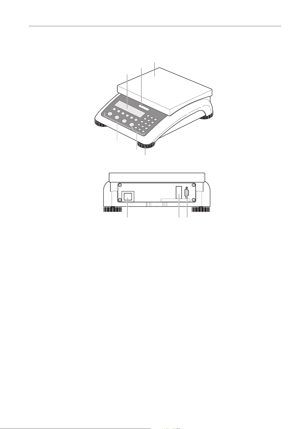
1.2.1 Overview
1 Display
2 Scale specifications
3 Load plate
4 Adjustable foot
5 Numerical keys
6 Function keys
IntroductionRanger RP
3
2
1
6
5
4
1 Power supply
connection
2 Optional interface
3 RS232 interface
321
7
Page 8
troduction
In
Ranger RP
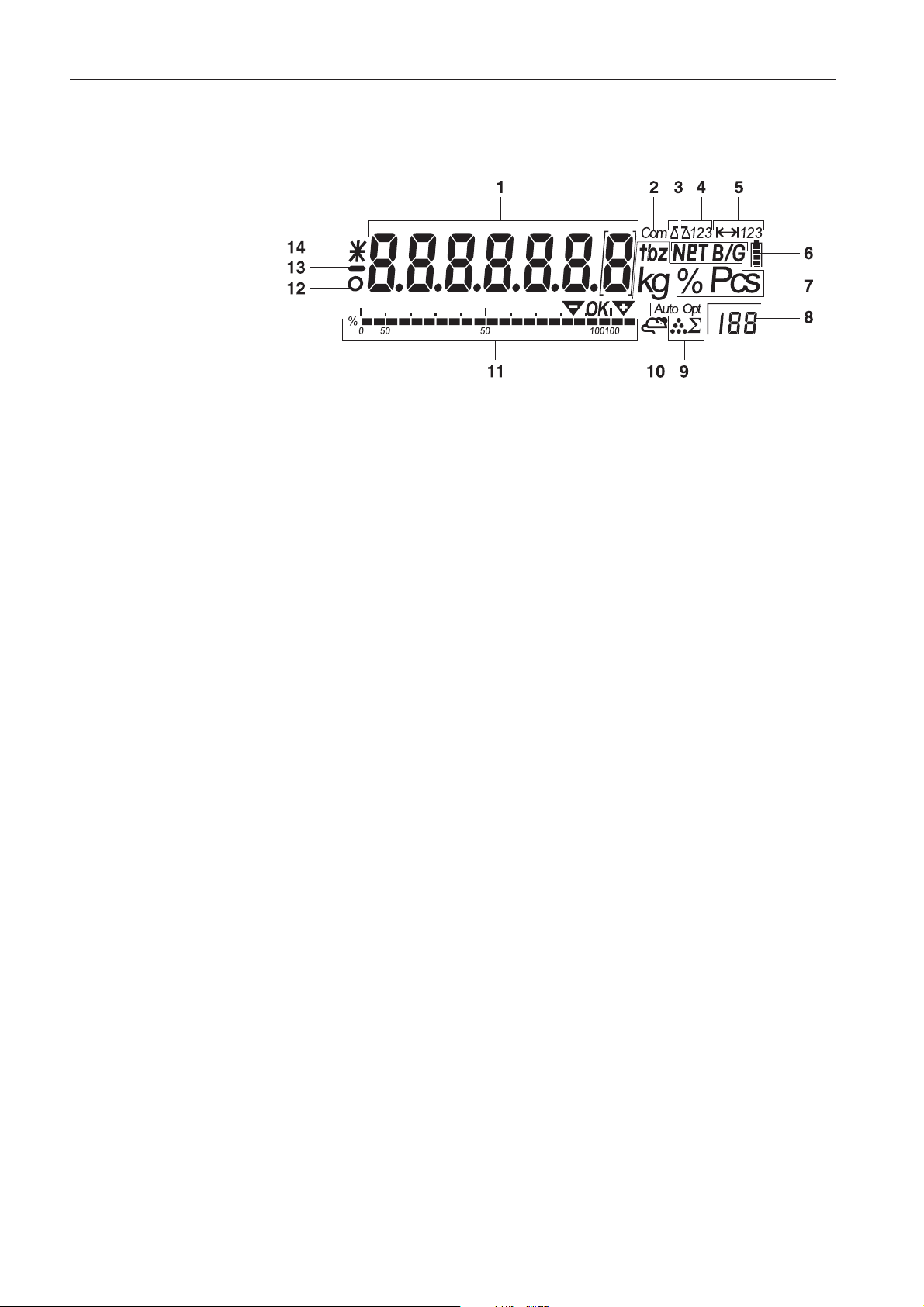
1.2.2 Display
1 7-segment display, 7 digits, with decimal point
2 Active interface
3 Symbol for displaying gross and net values
4 Active scale
5 Weighing range display
6 Battery charge level; only present on scales with a battery
7 Weight units
8 Selected reference quantity
9 Symbols for optimizing the average piece weight and accumulating
10 Symbol for dynamic weighing
11 Graphic display of the weighing range, display for checkweighing
12 Stability monitor (goes out when a stable weight value is reached)
13 Sign
14 Identification for changed or calculated weight values, e.g. higher resolution,
minimum weight not reached
8
Page 9
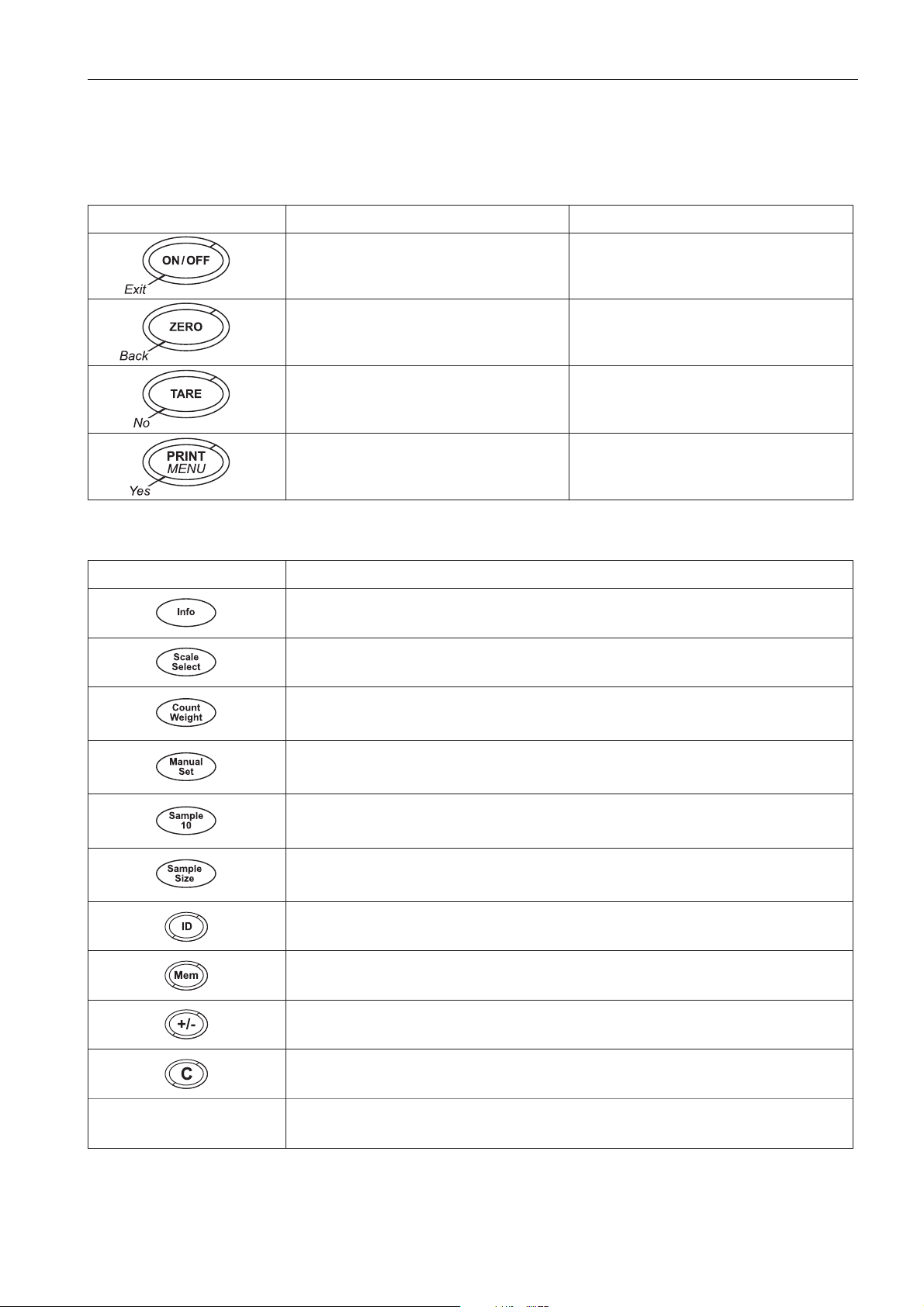
1.2.3 Keypad
Main
functions
Ke
y Function in operating mode Function in the menu
Switching device on / off, abort To the last menu item –End-
Setting scale to zero Scrolling back
Taring scale Scrolling forward
IntroductionRanger RP
Transfer
key press: Calling up menu
Long
Additional functions
Key Function
Info key: Calling up additional information, e.g. gross weight, average piece weight,
higher
resolution ...
Switching the scale
Switching between weight value and number of pieces
Weighing in reference or defining average piece weight numerically
Determining
Determining
key
Activating menu item
Accepting selected setting
average piece weight from 10 pieces
average piece weight from any number of pieces
Keys 0 .
point
.. 9 and decimal
ing identification
Enter
Memory
Sign; adding/subtracting
key
Clear
Numerical keys for entering weight values, identifications ...
9
Page 10
troduction
In
1.3 Putting into operation
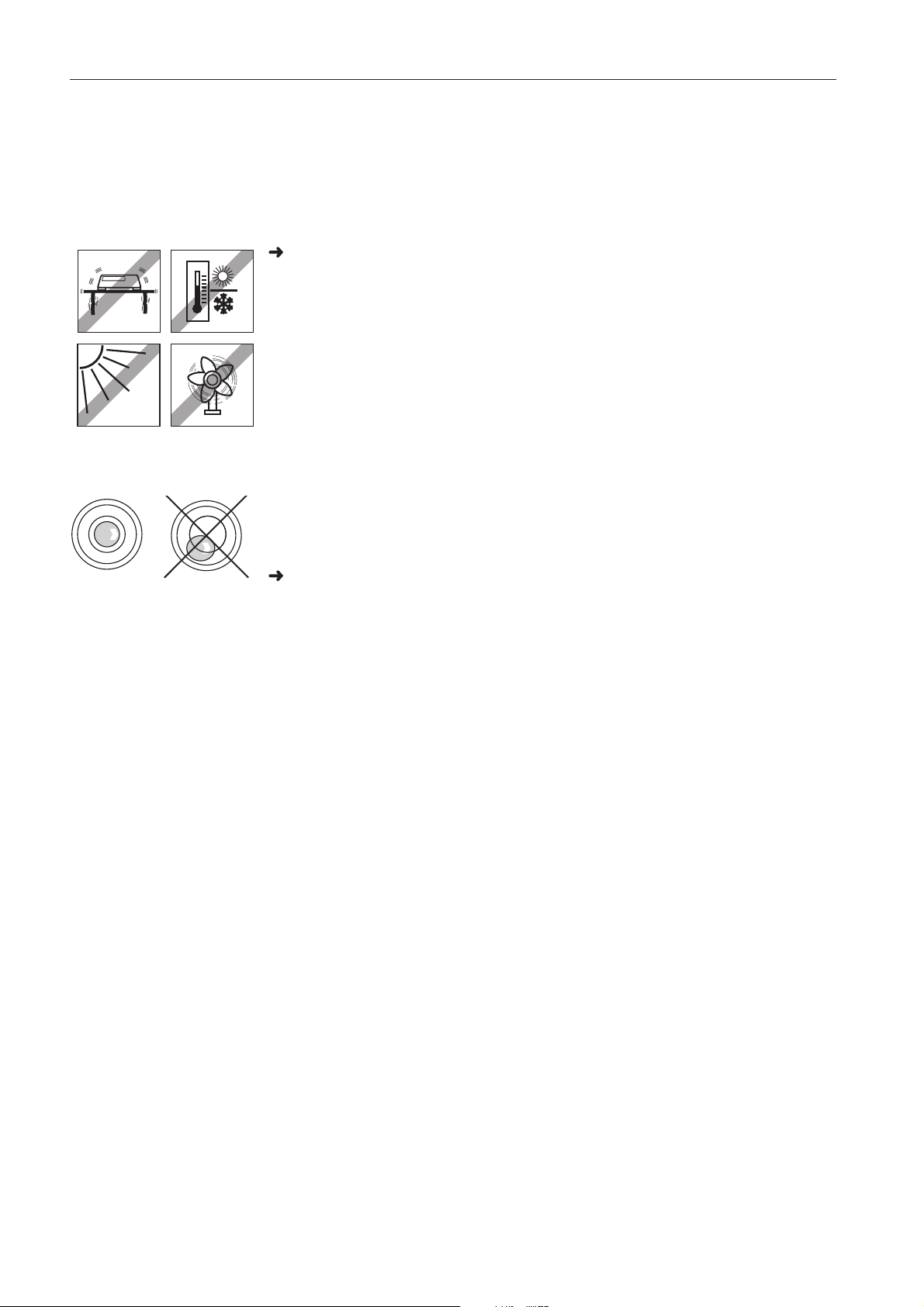
1.3.1 Selecting or changing the location
The correct location is crucial to the accuracy of the weighing results!
Select a stable, vibration-free and if possible a horizontal location.
ound must be able to safely bear the weight of the fully loaded scale.
The gr
Observe the following environmental conditions:
• No direct sunlight
• No strong drafts
• No excessive temperature fluctuations
Aligning the scale
Onl
y scales that have been aligned precisely horizontally provide accurate weighing
re
sults. The certified scales have a spirit level to simplify alignment.
Ranger RP
Major geographical
location
changes
Turn the adjustable feet of the scale until the spirit level’s air bubble is inside the
circle.
inner
The manufacturer adjusts each scale to the local gravity conditions (GEO value). In
the event of major geographical location changes, this setting must be adjusted by a
rvice technician. Certified scales must also be recertified observing the national cer-
se
cation regulations. These steps are not necessary for scales with an internal cali-
tifi
br
ation weight.
10
Page 11
1.3.2 Connecting the power supply
CAUTION!
Before connecting the scale to the mains, check whether the voltage value printed on
rating plate corresponds with the local mains voltage.
the
Never connect the device if the voltage value printed on the rating plate is different
local mains voltage.
to the
Plug the mains plug into the socket.
After connection, the device performs a self-test. When the zero display appears,
the
device is ready to weigh.
Calibrate the device in order to obtain the greatest possible precision, see
Sectio
n 4.3.2.
e Partially certified scales (scales with first-level certification) must be certified by an
Not
authorised body or by the OHAUS Service.
Call OHAUS Service.
IntroductionRanger RP
Scales with a built-in battery can work independently from the mains for approximately 30 hours in normal operation. A prerequisite for this is that the background
lighting is switched off and that no peripheral devices are connected.
The device automatically switches to battery operation as soon as the mains supply
is
interrupted. When the mains supply is restored, the device automatically switches
back to mains operation.
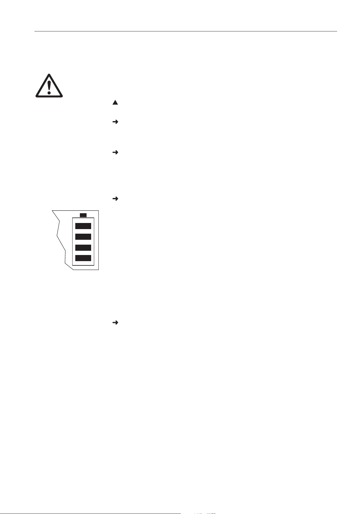
The
battery symbol indicates the present charging level of the battery. 1 segment cor-
res
ponds to approx. 25 % capacity. When the symbol flashes the battery must be
rged (min. 4 hours). The charging period is extended if work is continued during
cha
rging. The battery is protected against overcharging.
cha
e The battery’s charging capacity can be reduced under continuous mains operation.
Not
To maintain the charging capacity, after a maximum of 4 weeks discharge the bat-
completely before recharging it.
tery
11
Page 12

Operation
2 Operation
2.1 Switching on and off
Switching on Press ON/OFF.
Ranger RP
The scale conducts a display test. When the weight display appears, the scale is
dy to weigh.
rea
Switching
off Press ON/OFF.
Before
the display goes out, -OFF- appears briefly.
2.2 Zeroing / Zero point correction
Zeroing corrects the influence of slight changes on the load plate.
Manual 1. Unload scale.
2. Press ZERO.
The zero display appears.
Automatic In the case of scales that cannot be certified, the automatic zero point correction can
be deactivated in the menu or the amount can be changed.
As standard, the zero point of the scale is automatically corrected when the scale is
unloaded.
2.3 Simple weighing
1. Place weighing sample on scale.
2. Wait until the stability monitor goes out.
12
3. Read weighing result.
Page 13

2.4 Weighing with tare
2.4.1 Taring
Place the empty container on the scale and press TARE.
The zero display and the symbol NET appear.
The tare weight remains saved until it is cleared.
2.4.2 Clearing the tare
Unload scale and press TARE.
The
symbol NET goes out, the zero display appears.
or
Press C.
symbol NET goes out, the gross weight appears in the display.
The
If A.CL-tr is activated in the menu, the tare weight is automatically cleared as soon
as the scale is unloaded.
OperationRanger RP
.3 Automatic taring
2.4
Pr
erequisite
A-tArE is activated in the menu, the symbol T flashes in the display.
Place the container or packaging material on the scale.
The packaging weight is automatically saved as the tare weight, the zero display
and the symbol NET appear.
2.4.4 Numerical tare weight entry
1. Enter the known tare weight numerically and press TARE.
The
entered weight is automatically saved as the tare weight, the symbol NET and
the tare weight with a minus sign appear.
2. Place the filled container on the scale.
The net
weight appears in the display.
13
Page 14

Operation
2.4.5 Taring by calling up a saved tare value
Ranger RP have a total of 100 memory locations for frequently used tare values,
e piece weights, target weights and target quantities. In the factory setting,
averag
the
memory locations 01 to 40 are reserved for tare values. The saved tare values are
also
preserved when the scale is switched off.
Ranger RP
Saving
tare weights
1. Determine the tare weight in one of the ways described earlier.
2. Enter the memory location number (factory setting: 1 ... 40) and keep Mem
pressed until the confirmation appears in the display, e.g. tArE.12.
e If a tare weight had already been saved under the selected memory location, the mes-
Not
sage rEPLAC
• To save the new tare weight, press Yes. The old tare weight is overwritten.
• To abort the save process, press No. The previous memory location assignment
remains
Calling up tare we
E appears in the display.
valid.
ights
Enter the number of the memory location with the required tare weight (factory set-
1 ... 40) and press Mem briefly.
ting:
The selected tare value is loaded from the memory and appears briefly in the dis-
The scale tares with the selected tare value and then displays the current net
play.
weight.
Clearing
saved tare weights
14
1. Enter the number of the memory location with the tare weight to be cleared (factory
setting:
The
1 ... 40) and press Mem briefly.
saved tare value is displayed.
2. Press C within 2 seconds.
CLE
ArED briefly appears in the display. The saved tare value is cleared.
Page 15

2.4.6 Chain tare
Pr
erequisite
tare function CHAIn.tr is activated in the menu.
The
With this function it is possible to tare several times if, for example, cardboard is
pl
aced between individual layers in a container.
1. Place the first container or packaging material on the scale and press TARE.
The
packaging weight is automatically saved as the tare weight, the zero display
and the symbol NET appear.
2. Weigh the weighing sample and read/print out the result.
3. Place the second container or packaging material on the scale and press TARE
again.
The total weight on the scale is saved as the new tare weight. The zero display
appears.
4. Weigh the weighing sample in the second container and read/print the result.
5. Repeat the last two steps for other containers.
OperationRanger RP
2.5 Displaying the capacity available
The scale has a graphic display of the scale capacity available. The bar indicates how
ny per cent of the scale capacity is already occupied and what capacity is still
ma
available. In the example, approx. 65 % of the scale capacity is occupied.
2.6 Dynamic weighing
With the dynamic weighing function, it is possible to weigh restless weighing samples
as live animals. If this function is activated, the symbol appears in the dis-
such
pl
ay.
With
dynamic weighing, the scale calculates the mean value from 56 weighing oper-
within 4 seconds.
ations
With manual start Prerequisite
AVErAGE -> MAnuAL is selected in the menu.
weighing sample must be heavier than 5 scale divisions.
The
1. Place the weighing sample on the scale and wait until it has stabilized.
2. Press PRINT to start dynamic weighing.
During dynamic weighing, horizontal segments appear in the display, and the
dynamic result
is then displayed with the symbol *.
3. Unload the scale to be able to start a new dynamic weighing operation.
15
Page 16

Operation
With automatic start Prerequisite
AVErAGE -> AUtO is selected in the menu.
The
1. Place the weighing sample on the scale.
2. Unload the scale to be able to perform a new dynamic weighing operation.
2.7 Weighing-in to a target weight and checkweighing
The compact scales Ranger RP allow the weighing-in of goods to a particular target
weight within defined tolerances. With this function it is possible to check
whether weighing samples are within a defined tolerance range.
The compact scales Ranger RP have a total of 100 memory locations for frequently
used tare values, average piece weights, target weights and target quantities.
In the factory setting, the memory locations 81 to 90 are reserved for target weights.
The
Ranger RP
weighing sample must be heavier than 5 scale divisions.
The scale starts the dynamic weighing automatically.
During dynamic weighing, horizontal segments appear in the display, and the
dynamic result
is then displayed with the symbol *.
saved target weights are also preserved when the scales are switched off.
2.7
.1 Saving target weights
1. Enter the memory location number (factory setting: 81 ... 90) and keep Mem
pressed until the confirmation tArGEt appears in the display.
2. Enter the target weight in the defined unit, e.g. 1.5 kg, and confirm with Yes.
The display tOLER appears and + flashes.
3. Enter the upper tolerance in the displayed weight unit, e.g. 0.1 kg, and confirm with
Yes
-or-
Press Yes, enter the upper tolerance range in percent and confirm with Yes.
The display tOLEr appears and – flashes.
4. Enter the lower tolerance accordingly.
The
scale returns to weighing mode.
e If a target weight had already been saved under the selected memory location, the
Not
message rEPLACE appears in the display.
• To save the new target weight, press Yes. The old target weight is overwritten.
• To abort the save process, press No. The previous memory location assignment
remains valid.
16
Page 17
2.7.2 Calling up target weights
Enter the number of the memory location with the required target weight (factory
setting:
81 ... 90) and press Mem briefly.
The selected target weight and the tolerances are loaded from the memory and
appear
briefly in the display. The scale is now ready for weighing-in or check-
wei
ghing.
2.7
.3 Weighing-in
1. Place the empty container on the scale and tare.
2. Fill the container with the weighing sample.
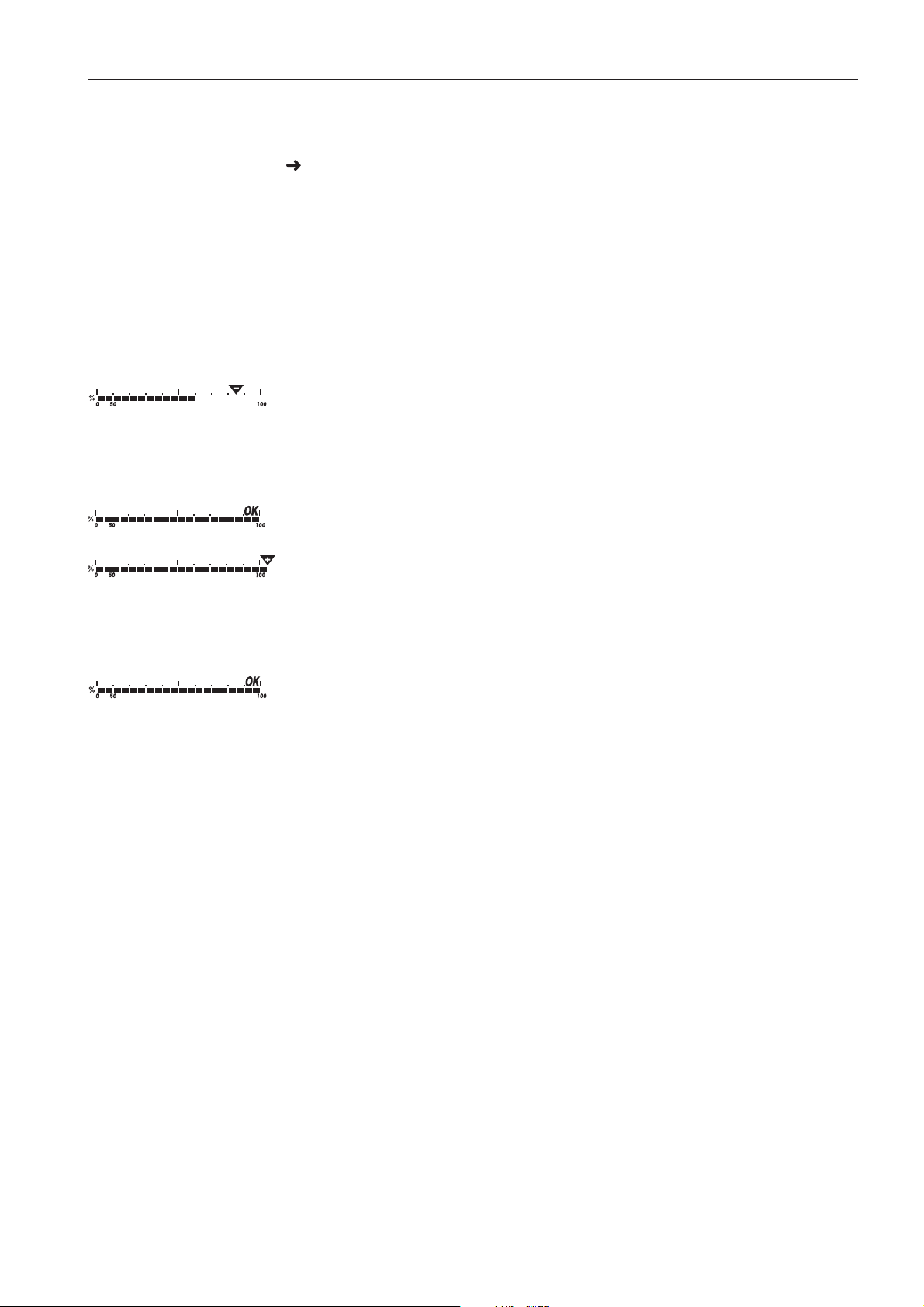
The dispensing process can be followed in the graphic display. The 50 % marking
is
on the far left here, so that more display segments are available for precise filling
be
tween 50 % and 100 %.
As long as the lower tolerance is not reached, the minus tolerance mark is displayed.
If the weight of the weighing sample is within the defined tolerance, the mark OK
is
visible and a short beep sounds if activated in the menu.
OperationRanger RP
When the plus tolerance mark appears, the weight is above the permissible tolerance.
2.7.4 Checkweighing
1. Place the weighing sample on the scale.
2. Use the displayed mark to check whether the weighing sample is below, within or
above
the defined tolerance.
.5 Clearing the saved target weights
2.7
1. Enter the number of the memory location with the target weight to be cleared (factory
setting: 81 ... 90) and press Mem briefly.
The
saved target weight is displayed.
2. Press C within 2 seconds.
CLE
ArED briefly appears in the display. The saved target weight is cleared.
17
Page 18

Operation
2.8 Working with identifications
Weighing series can be assigned 2 identification numbers ID1 and ID2 with up to
40 characters that are also printed out on the protocols.
If for example a customer number and an article number are assigned, it can be
clearly
seen on the protocol which article was weighed for which customer.
2.8
.1 Entering identification
1. Enter identification and press ID.
IdENt 1 appears in the display.
2. If the entered identification is to be saved as ID1, press Yes. If the entered identifi
cation is to be saved as ID2, first press No, and then press Yes.
The scale returns to weighing mode.
2.8
.2 Displaying identification
Displaying ID1: Briefly press ID once.
Ranger RP
The number currently assigned to the ID1 appears in the display. If no ID1 was
assigned,
Displaying ID2: Briefly press ID twice.
The number currently assigned to the ID2 appears in the display. If no ID2 was
assigned,
.3 Clearing identifications
2.8
1. Briefly press ID once to display ID1 or briefly press ID twice to display ID2.
2. Press C for as long as the identification is displayed.
The clearing is briefly confirmed with the message CLEArEd.
no Id appears.
no Id appears.
2.9 Printing results
If a printer or computer is connected to the scale, the weighing results can be printed
out
or sent to a computer.
Press PRINT.
The display contents are printed out and transferred to the computer. See
ion 8.4 for sample protocols.
Sect
18
Page 19

2.10 Displaying info
Up to 13 different values to be displayed can be configured in the menu for the key
Info.
Depending on the configuration in the menu, see Section 4.4.5, the following values
ca
n be stored in any order (for example):
• Net quantity
• Gross weight
• Average piece weight
• Average piece weight, higher resolution
• Counting accuracy
1. Press Info.
The first value is displayed.
2. Press Info again.
OperationRanger RP
The next value is displayed.
3. Repeat as often as necessary until the weight display appears again.
e If Info is not pressed again within 5 seconds , the scale automatically changes to the
Not
display, even if all information has not yet been queried.
weight
2.11 Switching scales
If a second scale or a weighing platform is connected, e. g. via the optional analog
cond scale interface, the currently active scale is shown in the display.
se
second scale can be operated in exactly the same way as the first scale.
The
Press Scale Select.
The d
isplay changes from one scale to the other.
19
Page 20

Operation
2.12 Totalising
The compact scales Ranger RP can totalise weight values or pieces. Individual items
can also be subtracted.
A connected printer offers you the possibility of generating a printout for each individual item and/or a complete printout. For settings in the menu, see Section 4.4.2.
2.12
.1 Totalising items
1. Place the first item on the scale and press +/-.
The
weight value or the number of pieces are saved and, if necessary, printed out.
2. Unload scale.
3. Place the next item on the scale and press +/- again.
The weight value and the number of pieces of the next item are added to those of
the previous one.
4. Unload scale.
5. Repeat steps 3 and 4 for all other items.
Ranger RP
2.12
.2 Subtracting items
1. Place the item on the scale, press and hold down +/-.
The weight value or the number of pieces are subtracted and, if necessary, printed
out.
2. Unload scale.
2.12.3 Completing totalising
When the last item has been totalised, press C.
The
"Final Printout" is produced. The sum memory and the item counter are
cleared. The scale is ready for the next totalising process.
2.12
.4 Calling up sum information
If
the key Info is assigned accordingly, the number of items, the net sum, the gross
and the number of pieces of the current item can be called up via this key, see
sum
n 4.4.5.
Sectio
20
Page 21

2.13 Cleaning
CAUTION!
Electric shock hazard!
Before cleaning with a damp cloth, pull out the mains plug to disconnect the unit
from
the power supply.
CAUTION!
When the weighing pan has been removed, never clean the area under the load plate
holder with a solid objec
This could damage the weighing cell.
Other cleaning information:
• Use damp cloths.
• Do not use any acids, alkalis or strong solvents.
OperationRanger RP
t!
• Do not clean using a high-pressure cleaning unit or under running water.
• If very dirty, remove the weighing pan, protective cover (if present) and adjustable
and clean these items separately.
feet
• Follow all the relevant instructions regarding cleaning intervals and permissible
cleaning
agents.
21
Page 22

Counting
3 Counting
The compact scales Ranger RP have additional functions for piece counting.
The relevant settings in the menu are described in Section 4.4.1.
3.1 Counting parts into a container
1. Place the empty container on the scale and press TARE.
The container is tared and the zero display appears.
2. Place 10 reference parts on the scale and press Sample 10.
-or-
Place the number of pieces displayed above the key Sample Size on the scale
and press Sample Size
The scale determines the average piece weight and then shows the number of
ces.
pie
Ranger RP
Not
3. Add more parts to the container until the required number of pieces is reached.
4. When the piece counting is completed, press the key C to clear the result.
The scale is ready for the next weighing or counting.
e
• The average piece weight remains saved in the factory setting until a new average
ce weight is determined.
pie
• With Count Weight it is possible to switch between the number of pieces and the
weighing units preset.
• Depending on the assignment, it is possible to display the average piece weight,
i. e. the weight of an individual reference unit, with Info.
• If A.CL-APW ON is set in the menu, the average piece weight is automatically
cleared
mined
• If ACCurCY ON is set in the menu, the accuracy achieved is briefly shown after
the
after each counting operation. The average piece weight must be deter-
again for the next counting operation.
number of pieces is determined.
22
Page 23

3.2 Counting parts out of a container
1. Place the full container on the scale and press TARE.
The container is tared and the zero display appears.
2. Remove 10 reference parts and press Sample 10.
-or-
Remove the number of pieces displayed above the key Sample Size and press
Sample Size.
The scale determines the average piece weight and then shows the number of
pie
ces removed, together with a minus sign.
3. Remove more parts from the container until the required number of pieces is
reache
d.
3.3 Counting with variable reference quantity
Prerequisite
CountingRanger RP
VAr-SPL ON must be set in the menu.
1. Place any number of reference parts on the scale.
2. Enter the number of reference parts with the numerical keypad and press Sample
Size
The scale determines the average piece weight and then shows the number of
pie
ces.
The rest of the counting process is as described earlier.
3.4 Counting with minimum accuracy
The item Min.rEFW in the menu allows to preset a minimum accuracy of 97.5 %,
0 % or 99.5 %. On the basis of this, the scale calculates the minimum reference
99.
wei
ght necessary to reach the defined accuracy.
1. Place the reference parts on the scale and press Sample 10 or Sample Size.
2. If the average piece weight is not sufficient to ensure the desired accuracy,
d x PCS appears.
Ad
3. Add the displayed number of pieces.
scale then automatically determines the average piece weight with the larger
The
reference qu
antity.
rest of the counting process is as described earlier.
The
23
Page 24

Counting
3.5 Reference optimization
The greater the reference quantity, the more accurately the scale determines the
number
.1 Automatic reference optimization
3.5
rEF.OPt -> AUtO must be set in the menu for this. The symbol Auto Opt appears
in the display.
1. Place the reference parts on the scale and press Sample 10 or Sample Size.
2. Place additional reference parts, max. the same number as for the first reference
The
e The reference optimization can be performed several times.
Not
of pieces.
determination, on the scale.
scale automatically optimises the average piece weight with the larger number
The
of reference parts
rest of the counting process is as described earlier.
.
Ranger RP
3.6 Counting with automatic reference determination
Prerequisite
A-SMPL ON is set in the menu.
➜ Place the number of pieces displayed above the key Sample Size into the
container.
The scale automatically determines the average piece weight and then shows the
quantity.
The
rest of the counting process is as described earlier.
3.7 Counting with a known average piece weight
➜ Enter the known average piece weight via the numerical keypad and press Manual
Set
.
The scale changes the unit to PCS.
The
rest of the counting process is as described earlier.
24
Page 25

3.8 Counting by calling up a saved average piece weight
The compact scales Ranger RP have a total of 100 memory locations for frequently
used tare values, average piece weights, target weights and target quantities.
In the factory setting, the memory locations 41 to 80 are reserved for average piece
weights.
sw
1 Saving average piece weights
3.8.
1. Determine the average piece weight in one of the ways described earlier.
2. Enter the memory location number (factory setting: 41 ... 80) and keep Mem
e If an average piece weight had already been saved under the selected memory loca-
Not
tion,
• To save the new average piece weight, press Yes. The old average piece weight
The saved average piece weights are also preserved when the scale is
itched off.
pressed until the confirmation appears in the display, e.g. APW.41.
the message rEPLACE appears in the display.
is overwri
tten.
CountingRanger RP
• To abort the save process, press No. The previous memory location assignment
remains valid.
.2 Calling up average piece weights
3.8
Enter the number of the memory location with the required average piece weight
(factory
setting: 41 ... 80) and press Mem briefly.
The selected reference value is loaded from the memory and appears briefly in the
y. The scale determines the number of pieces with the selected reference
displa
value.
.3 Clearing saved average piece weights
3.8
1. Enter the number of the memory location with the average piece weight to be
cleared
The
(factory setting: 41 ... 80) and press Mem briefly.
saved average piece weight is displayed.
2. Press C within 2 seconds.
ArED briefly appears in the display. The saved average piece weight is
CLE
cleared
.
25
Page 26

Counting
3.9 Counting by calling up a saved target quantity
The compact scales Ranger RP have a total of 100 memory locations for frequently
used tare values, average piece weights, target weights and target quantities.
In the factory setting, the memory locations 91 to 100 are reserved for target quantitie
s. The saved target quantities are also preserved when the scale is switched off.
3.9
.1 Saving target quantities
1. Enter the memory location number (factory setting: 91 ... 100) and keep Mem
pressed until the confirmation tARGEt appears in the display.
2. Enter the target quantity and confirm with Yes.
The display tOLEr appears and + flashes.
3. Enter the upper tolerance in pieces and confirm with Yes.
The display tOLEr appears and – flashes.
4. Enter the lower tolerance accordingly.
The scale returns to weighing mode.
Ranger RP
e If a target quantity had already been saved under the selected memory location, the
Not
message rEPLACE appears in the display.
• To save the new target quantity, press Yes . The old target quantity is overwritten.
• To abort the save process, press No. The previous memory location assignment
remains valid.
3.9
.2 Calling up target quantities
Enter the number of the memory location with the required target quantity (factory
setting:
The
memory
.3 Counting in to target quantities
3.9
91 ... 100) and press Mem briefly.
selected target quantity and the associated tolerances are loaded from the
and appear briefly in the display.
1. Place the empty container on the scale and tare.
2. Specify a reference.
3. Fill the container with the material being counted.
counting-in process can be followed in the graphic display. The 50 % marking
The
is
on the far left here, so that more display segments are available for precise filling
between 5
0 % and 100 %.
26
long as the lower tolerance is not reached, the minus tolerance mark is dis-
As
played.
If
the counted-in number of pieces is within the defined tolerance, the mark OK is
visible
and a short beep sounds if activated in the menu.
When the plus tolerance mark appears, the number of pieces is above the permis-
tolerance.
sible
Page 27

3.9.4 Clearing saved target quantities
1. Enter the number of the memory location with the target quantity to be cleared (fac setting: 91 ... 100) and press Mem briefly.
tory
The saved target quantity with tolerances is displayed.
2. Press C within 2 seconds.
CLEArED briefly appears in the display. The saved target quantity is cleared.
3.10 Counting with two scales
For piece counting, it is possible to connect a second scale or weighing platform, e. g.
a floor scale for counting a large number of pieces via the optional analog second
scale
interface.
The necessary settings for the application and interface parameters are described in
the Sections 4.
3.10.
1 Counting with a reference scale
4.1, 4.6.1 and 4.6.4.
CountingRanger RP
Not
erequisite
Pr
The connected second scale is configured as reference scale.
1. Place the reference parts on the reference scale and press Sample 10 or Sample
Size.
The scale determines the average piece weight and changes to the display in
ces (PCS).
pie
2. Place the parts to be counted on the first scale.
The total quanti
e
• If tOtAL-Ct -> bULK is set in the menu, only the number of pieces on the bulk
ty is displayed.
scale is displayed.
• If tOtAL-Ct -> bOtH is set in the menu, the reference quantity is added to the
bulk quant
ity.
27
Page 28

Counting
3.10.2 Counting with a bulk scale
Pr
erequisite
connected second scale is configured as bulk scale.
The
1. Place the reference parts on the first scale and press Sample 10 or Sample Size.
scale determines the average piece weight and changes to the display in
The
pie
ces (PCS).
2. Place the parts to be counted on the bulk scale.
The total quantity is displayed.
e
Not
• If tOtAL-Ct -> bULK is set in the menu, only the number of pieces on the bulk
scale is displayed on the bulk scale.
• If tOtAL-Ct -> bOtH is set in the menu, the reference quantity is added to the
bulk quantity.
.3 Counting with an auxiliary scale
3.10
Ranger RP
e This configuration allows counting of diverse parts, for example very small parts on
Not
scale and large parts on the other scale.
one
erequisite
Pr
The connected second scale is configured as an auxiliary scale. The scale doesn’t
chang
e automatically but only after pressing the Scale Select key.
1. Activate the appropriate scale.
2. Place the reference parts on this scale and press Sample 10 or Sample Size.
The scale determines the average piece weight and changes to the display in
pie
ces (PCS).
3. Place the parts to be counted on the same scale.
number of pieces is displayed.
The
28
Page 29

4 Settings in the menu
Settings can be changed and functions can be activated in the menu. This enables
adaptation to individual weighing requirements.
The menu consists of 6 main blocks containing various submenus on several levels.
4.1 Operating the menu
4.1.1 Calling up the menu and entering the password
The menu differentiates between 2 operating levels: Operator and Supervisor. The
Supervisor level can be protected by a password. When the device is delivered, both
levels are accessible without a password.
Operator menu 1. Press MENU and keep it pressed until COdE appears.
2. Press MENU again.
Settings in the menuRanger RP
The menu item tErMINL appears. Only the submenu dEVICE is accessible.
Supervisor menu 1. Press MENU and keep it pressed until COdE appears.
2. Enter the password and confirm with Yes.
The
first menu item SCALE appears.
e No supervisor password has been defined when the device is first delivered. Therefore
Not
respond
If a password has still not been entered after a few seconds, the scale returns to weighing mode.
Emergency password for Supervisor access to the menu
If
got
to the password inquiry with MENU when you call up the menu for the first time.
a password has been issued for Supervisor access to the menu and you have for-
ten it, you can still enter the menu:
Press ZERO 3 times and confirm with Yes.
29
Page 30

tings in the menu
Set
COdE
Ranger RP
4.1.2 Selecting and setting parameters
SCALE
CAL dISPLAY tArE
APPLIC
...
tErMIN
dEVICE ACCESS
PWr.OF
SLEEP
L COMMUNI
rESEt
F b.LIGHt
Scrolling on one level Scroll forward: Press No.
Scroll back: Press Back.
COM 1
MOdE
COM 2
PriNtE
dIAGNOS
...
r PArAMEt
rSt
.
COMX
End
Activating
accepting se
30
menu items/
lection
Exiting men
Press Yes.
u 1. Press Exit.
The
last menu item END appears.
2. Press Yes.
The
inquiry SAVE appears.
3. Confirm inquiry with Yes to save the settings and return to weighing mode.
-or-
Press No to discard changes and return to weighing mode.
Page 31

Settings in the menuRanger RP
4.2 Overview
Level 1 Level 2 Level 3 Level 4 Level 5 Level 6 Page
SCALE SCALE1/SCALE2 34
CAL 34
dISPLAY UNIt1
UN
It2 g, kg, oz, lb, t
g, kg, oz, lb, t
35
rESOLU
UNt.rOLL
tArE A-tArE
AIn.tr ON, OFF
Ch
A.CL-tr
ON
ON
ON
, OFF
, OFF
, OFF
35
ZErO AZM OFF; 0.5 d; 1 d; 2 d; 5 d; 10 d 35
rEStArt
ON
/OFF
FILtEr VibrAt
OCESS UNIVEr, dOSING
Pr
LOW
, MEd, HIGH,
35
35
StABILI FASt, StAndrd, PrECISE
FACt tEMP
dA
Y.tIM OFF, dAY, tIME
Min.WEiG ON/OFF
OFF, 1K
ON
, OFF
, 2K, 3K, 5K
36
36
rESEt SUrE? 37
APPLI
C COUNt VAr-SPL
L-qtY Sq1 ... Sq5
SP
n.reFW OFF, 97.5%, 99.0%, 99.5%
Mi
rE
F OPt OFF, AUtO
SMPL
A-
A.
CL-APW
AC
CurCY
tO
tAL.Ct bULK, bOth
ACCUMUL Print COM1, COM2 LOt.PrNt 38
rE
ACH Z
CHECKW bEEPEr
SP
.tOL-
SE
Nd.MOd CONtINU, StAbLE
ON
, OFF
ON
, OFF
ON
, OFF
ON
, OFF
ON, OFF
ON
, OFF
FIN.
SUMM
37
PrNt
ArY
38
31
Page 32

tings in the menu
Set
Ranger RP
Level 1 Level 2 Level 3 Level 4 Level 5 Level 6 Page
MEMOrY CONFIG 39
CLEAr.M SUrE?
inFO.KEY INFO 1 ...
FO 13
IN
Not.USE
APW, HI
d, PCS NEt, GrOSS, tArE,
GHrES, ACCurCY, n, G tOtAL,
40
N tOtAL, PCS.tOtL, tArGEt, dAtE, timE
AVErAGE OFF, AUtO, MAnuAL 40
rESEt SUrE? 40
tERMINL dEVICE SLEEP OFF, 1 min, 3 min, 5 min 41
r OFF YES, NO
PW
b.LIGHt
dA
tE.tim dAtE.FOr, dAtE, timE, AM.PM
bEEP
ON
, OFF
ON
, OFF
ACCESS SUPErVI 41
rESEt SUrE? 42
COMMUNI COM 1/COM 2 MOdE Print 42
A.Print
CONtINU
dIALOG
CONt.OL
d
dIAL.OL
dt-
dt-
COnt-W
COnt-C
bArc.r
2nd.dIS
F
rE
bUL
AuXILI
d
b GrOSS ON, OFF
E ON, OFF
tAr
t ON, OFF
nE
G GrOSS ON, OFF
tAr
E ON, OFF
t ON, OFF
nE
t
t
d
P
K
A
32
Page 33

Settings in the menuRanger RP
Level 1 Level 2 Level 3 Level 4 Level 5 Level 6 Page
PriNtEr tEmPLat StdArd, tEMPLt1,
Lt2
tEMP
ASCi.Fm
t LINE.FMt MULtI
43
SINGLE
LENGtH 1 ... 100
SEPArAt , ;...
Add LF 0 ... 9
PArAMEt bAUd 300 ... 38400 43
PArit
Y 7 nonE, 8 nonE, 7 odd,
8 odd, 7 EVEN, 8 EVEN
H.SHAKE NO, XONXOFF, nEt 422,
485
nEt
NEt.Add
ChECSu
Vcc
t.COMx SUrE? 43
rS
r 0 ... 31
M
ON
ON
, OFF
, OFF
COMMUNI OPtION EtH.NEt IP.AddrS, SUbNEt, GAtEWAY 43
USb USb tESt 43
diGitAL IN 1 ... 4 OFF, ZErO, tArE,
ALOG Mode rEF, bULK, AuXILIA,
AN
dEF.PrN tEMPLt1/
MPLt2
tE
t, CLEAr, rEF 10,
Prin
F n, SCALE, inFO,
rE
Unit
, tOtAL+, tOtAL–
OUT 1 ... 4 OFF, StAbLE, bEL.Min,
Min, bEL.tOL-,
AbV.
tOL+, GOOd,
AbV.
UndE
rLd, OVErLd, StAr
SS
bYPA
LINE
LINE 2
1 ...
0
NOt.
USEd, HEAdEr,
, timE, Id1, Id2,
dAte
SCAL
E.NO, GrOSS, tArE,
APW, rEF Ct, PCS,
nEt,
Et, dEVIAt,
tArG
AC
C NEt, ACC GrS,
C PCS, ACC LOt,
AC
LN, CrLF, F FEEd
StAr
43
43
45
33
Page 34

tings in the menu
Set
Ranger RP
Level 1 Level 2 Level 3 Level 4 Level 5 Level 6 Page
dIAGNO
S tESt SC intErN/ExtErN 46
KboArd
dISPLAY
SNr
SNr2
LiSt
LiSt2
LiSt.M
WOrK.tim timE SHOW.tIM
WEIGH SHOW.WGH
rESEt.AL SUrE?
4.3 Scale settings (SCALE)
4.3.1 SCALE1/SCALE2 – Selecting scale
This menu item only appears if an analog second scale or a weighing platform is connected.
.2 CAL – calibration (adjustment)
4.3
is menu item is not available for certified scales without internal calibration weight.
Th
Internal For scales with an internal calibration weight:
1. Unload scale.
2. Activate menu item CAL with Yes. The scale calibrates with the internal calibration weight. -Int CAL- appears in the display. After calibration is completed,
E- appears briefly in the display, and the scale automatically returns to
-don
wei
ghing mode.
Externa
l For scales without an internal calibration weight:
1. Unload scale.
2. Activate menu item CAL with Yes. The scale determines the zero point.
–0
- appears in the display. The calibration weight to be placed on the scale then
in the display.
flashes
3. If necessary, change the weight value displayed with No.
4. Place the calibration weight on the scale and confirm with Yes.
scale calibrates with the calibration weight loaded. After calibration is com-
The
pleted, -donE
- appears briefly in the display, and the scale automatically returns
to weighing mode.
34
Page 35

Settings in the menuRanger RP
4.3.3 DISPLAY – weighing unit and display accuracy
UNIt
1 Select weighing unit 1: g, kg, oz, lb, t
UNIt2 Select weighing unit 2: g, kg, oz, lb, t
rESOLU Select readability (resolution), model-dependent
UNt.rOLL When UNT.rOLL is switched on, the weight value can be displayed in all available
units and as pieces with Count Weight.
Notes
.4 TARE – tare function
4.3
• On certified scales, the weighing units oz and lb are displayed with the symbol *.
• On certified scales, resolutions that deviate from the scale definition are displayed
thout a weighing unit and with the symbol *.
wi
• On dual-range/dual interval scales, resolutions marked with |<–> 1/2| are
divided
up into 2 weighing ranges / intervals, e.g. 2 x 3000 d.
A-tArE Switching on/off automatic taring
CHAIn.tr Switching on/off chain tare
A.CL-tr Switching on/off automatic taring with automatic clearing of the tare weight when the
load
is removed from scale
5 ZERO – automatic zero update
4.3.
AZM On certified scales, this menu item does not appear.
Switching on/off automatic zero update and selecting zeroing range.
Possible settings: OFF; 0.
5 d; 1 d; 2 d; 5 d; 10 d
.6 RESTART – automatic saving of zero point and tare value
4.3
ON/OFF When the Restart function is activated, the last zero point and tare value are saved.
After switching off / on or after a power interruption, the device continues to work with
saved zero point and tare value.
the
.7 FILTER – adaptation to the ambient conditions and the weighing type
4.3
VIbrAt Adaptation to the ambient conditions
W
LO
• Very steady and stable environment. The scale works very quickly, but is very
sensitive to external influences.
ME
d • Normal environment. The scale operates at medium speed.
HI
GH • Restless environment. The scale works more slowly, but is insensitive to external
influenc
es.
35
Page 36

tings in the menu
Set
Ranger RP
PrOCES
S Adaptation to the weighing process
UNIVEr
dOSING
• Universal setting for all weighing samples and normal weighing goods
• Dispensing liquid or powdery weighing samples
StAbILI Adjusting the weighing speed
FASt
StAndrd
PrECISE
• The scale operates very fast.
• The scale operates at medium speed.
• The scale operates with the greatest possible reproducibility.
The slower the scale works, the greater the reproducibility of the weighing results.
4.3.8 FACT – automatic temperature-dependent adjustment
Th
is menu item appears only on scales with an internal calibration weight.
TEMP Defining the temperature difference for automatic calibration
OF
F • Switching off automatic calibration in the case of a temperature difference
1K
/2K/3K/5K
• Automatic calibration in the case of a temperature change of 1 K, 2 K, 3 K or 5 K
the last adjustment
since
dAY.tim Defining up to 7 days of the week and up to 3 times for automatic adjustment.
dAY
• Select day of the week for the adjustment.
7 zeros appear in the display after pressing the key Yes. The first zero stands for
Monday, the second for Tuesday, the third for Wednesday etc.
Use the key No to go to the desired day of the week and enter 1.
The display 0100100 means that Tuesday and Friday are selected as calibration
days.
Press Yes.
tiME
1 appears in the display.
ti
ME1...3
• Enter the time(s) for the calibration (hours, minutes).
Note The format for entering the time (EU or US) depends on the settings in the menu item
MINAL-> Device, see section 4.5.1.
TER
.9 MIN.WEIG – minimum weight
4.3
Th
is menu item appears only if the service technician has saved a minimum weight.
ON/OFF Switching minimum weight function on/off
If the weight on the scale falls below the stored minimum weight, an * appears on
the display in front of the weight indicator.
36
Page 37

4.3.10 RESET – resetting scale settings to factory settings
SUrE
? Confirmation inquiry
• Reset the scale settings to factory settings with Yes
• Do not reset scale settings with No
4.4 Application settings (APPLICATION)
4.4.1 COUNT – settings for counting
VAr-SPL Adaptation of the reference quantity
ON • The reference quantity can be changed in operating mode
OF
F • Counting only with defined reference quantities
Settings in the menuRanger RP
Min.re
FW Monitoring the minimum reference weight
F
OF
97
.5, 99.0,
.5
99
• No monitoring of the minimum reference weight
• Monitoring the minimum reference weight so that a counting accuracy of
5 %, 99.0 % or 99.5 % is achieved
97.
rEF.OPt Optimizing the average piece weight
OFF
AUtO
• No reference optimization
• Automatic reference optimization
A-SMPL Automatic determination of the average piece weight
ON
• After taring, the average piece weight is determined with the next weight placed
on the scale and the displayed reference quantity
OF
F • No automatic determination of the average piece weight
A.CL-A
PW Automatic clearing of the average piece weight
ON
• When the load is taken off the scale after a counting operation, the average piece
weig
ht is automatically cleared. The next counting operation begins with deter-
mining the average piece weight again.
F
OF
• The average piece weight must be cleared manually by pressing C
ACCurCY Displaying the counting accuracy
ON
• After the average piece weight is determined, the counting accuracy that can be
ved is shown briefly in the display.
achie
OF
tOtAl.
bU
bO
F • No counting accuracy display
Ct Counting on two scales
LK
• Display number of pieces for the parts on the bulk scale only
th • Display number of pieces for all parts on the bulk and the reference scale
37
Page 38

tings in the menu
Set
4.4.2 ACCUMULATION – totalising
PrINt Configure printout for accumulation
COM 1/COM 2 Select interface for the connected printer / computer
Ranger RP
LOt.PrINt
FIN.PrINt
SUMMArY
• Printout for each individual item
• Printout only at the end of accumulation
• Additional printout of the individual items after completion of accumulation
rEACH Z Reach a stable zero point between two items
ON
• All load must first be removed from the scale before accumulation of the next item
is possible
OFF
4.4
.3 CHECKWEIGHING
• No load removal requested between two items
bEEPEr Setting the beep for checkweighing
ON
OFF
• A short beep sounds when the target value is reached
• No beep
SP.tOL– Limit for activation of the I/O relay box. The value to be entered is the percentage
proportion of the lower tolerance of the target weight / target quantity.
EXAMPLE
Target
weight:2000 g
LER+:2010 g
tO
SENd.M
CO
St
LER-:1990 g
tO
SP.tOL-:010 (%)
The relay box is not activated until 199 g (= 10 % of 1990 g) is reached.
Od Defines the form in which the scale sends information to the I/O relay box
NtINU
• Information is permanently sent
AbLE • Information is only sent if the weight value is stable
38
Page 39

4.4.4 MEMORY – configuring memory
Settings in the menuRanger RP
CONFI
G Configuring the memory partitions.
40-40-10 Ranger RP have a total of 100 memory localizations that can be assigned
to tare values, average piece weights, target weights and target quantities.
Factory
• 40 memory locations for tare values (01-40)
• 40 memory locations for average piece weights (41-80)
• 10 memory locations with target weights (81-90)
• 10 memory locations with target quantities (91-100)
The f
settings:
irst target weight is called up e.g. with memory address No. 81.
Changing the range for the memory locations:
1. Enter the new range and separate each range with a point (e. g. 30.30.20). The
last range is automatically calculated. If an invalid entry is made, NOt.ALLO
is shown in the
display.
2. Confirm with Yes.
Since
only some of the entered values can be shown in the display, the display can
be moved to the right with the aid of the No key.
Note
After every new partitioning, always check the memory values and adjust if necessary!
CLEAr.M Clearing all memories.
39
Page 40

tings in the menu
Set
INFO
1 Up to 13 additional values can be displayed via the key Info.
NO
t.USEd
Ranger RP
4.4.5 INFO-KEY – assignment of the Info key
• Info space not occupied
PCS NEt
GrOSS
tArE
APW
HIGHrES
CUrCY • Displays counting accuracy
AC
• Displays net weight in counting
• Displays gross weight
• Displays tare weight
• Displays average piece weight
• Shows display with a higher resolution
n • Displays number of totalised items
G
tOtAL • Displays gross sum
N
tOtAL • Displays net sum
PC
S.tOtL • Displays sum of pieces
tA
rGEt
• Displays target value and tolerances
dAtE • Displays date
ti
mE • Displays time
INFO2
... INFO13 As per INFO1
.6 AVERAGE – determining the average weight for an unstable load
4.4
OFF Calculating average weight switched off
AUt
O Calculating average weight with automatic start of the weighing cycle
MAnuA
L Calculating average weight with manual start of the weighing cycle via PRINT
.7 RESET – resetting application settings to factory settings
4.4
SUrE? Confirmation inquiry
• Reset the application settings to factory settings with Yes
• Do not reset the application settings with No
40
Page 41

4.5 Terminal settings (TERMINAL)
4.5.1 DEVICE – Sleep mode, energy-saving mode and display backlighting
SLEE
P This menu item only appears on devices in mains operation.
When SLEEP is activated, the scale switches off display and backlighting after the
time period set when not in use. The display and backlighting are switched on again
at
the press of a key or if the weight changes.
Possible settings: OFF, 1 min, 3 min, 5 min
PWr OFF This menu item only appears on devices in battery operation.
When PWr OFF is activated, the device switches itself off automatically after
approx. 3 minutes when not in use.
b.LIGHt Switching the display backlighting on/off.
On scales with a battery, the background lighting switches itself off automatically if
there has been no activity on the scale for 5 seconds.
DAtE.tim Setting date and time
Settings in the menuRanger RP
DAtE.FOr
DAtE
tIME
AM.PM
• Select type of date setting: EU or US
• Enter the date in the selected format
• Enter the time
• Select AM/PM
bEEP Switching beep on/off
ON Switching on beep on each key press
F Switching off beep on each key press
OF
Not
e This menu item is accessible without a Supervisor password.
.2 ACCESS – password for Supervisor menu access
4.5
SUPErVI Password entry for Supervisor menu access
tER.C Request to enter password
EN
Enter the password and confirm with Yes
rEtYPE.C Request to repeat the password entry
Enter the password again and confirm with Yes
Notes
• The password can consist of up to 4 characters.
• The key Yes must not be part of the password. It is required for confirming the
password.
• The key No may only be used in combination with another key.
• If you enter an impermissible code or make a typing error in the repetition,
.Err. appears in the display.
COdE
41
Page 42

tings in the menu
Set
4.5.3 RESET – resetting terminal settings to the factory settings
SUrE
? Confirmation inquiry
• Reset terminal settings to the factory settings with Yes
• Do not reset the terminal settings with No
4.6 Configuring interfaces (COMMUNICATION)
4.6.1 COM1/COM2 -> MODE – operating mode of the serial interface
Print Manual data output to the printer with PRINT
Ranger RP
A.Prin
CONtIN
dIALO
t Automatic output of stable results to the printer (e. g. for series weighing operations)
U Ongoing output of all weight values via the interface
G Bi-directional communication via OHAUS or MT-SICS commands, control of the
scale via PC
CONt.O
Ld As per CONtINU, see above, but with 2 fixed blanks in front of the unit (compatible
with Spider 1/2/3)
dIAL.OLd As per dIALOG, see above, but with 2 fixed blanks in front of the unit (compatible
with Spider 1/2/3)
dt-
b DigiTOL-compatible format.
OSS
GR
tArE
• Transfer of the gross weight, identified with "G"
•
Transfer of the tare weight
nEt • Transfer of the net weight
dt-
G As per dt-b, see above, gross weight identified with "G"
COnt-W
COnt-C
bArc.r
2nd.dI
t TOLEDO Continuous mode
t TOLEDO Continuous mode, transfer of the number of pieces
d For connecting a serial bar code reader (automatically activates the 5-V voltage sup-
ply
at Pin 9)
SP For connecting a second display (automatically activates the 5-V voltage supply at
)
Pin 9
rE
F Data transfer from the reference scale (automatic switchover)
K Data transfer from the quantity scale (automatic switchover)
bUL
AuXILI
42
A Data transfer from the reference or quantity scale (manual switchover)
Page 43

4.6.2 COM1/COM2 -> PRINTER – settings for protocol printout
This menu item only appears if the mode "Print" or "A.Print" is selected.
Settings in the menuRanger RP
tEmPLa
t Selecting protocol printout
StdArd
mPLt1
tE
tEmPLt2
• Standard printout
• Printout in accordance with Template 1
• Printout in accordance with Template 2
ASCi.FmtT Selecting formats for the protocol printout
LINE.Fmt
LENGtH
SEPArAt
Add LF
.3 COM1/COM2 -> PARAMET – communication parameter
4.6
• Line format: MULtI (multi-line) or SINGLE (single-line)
• Line length: 0 ... 100 characters, appears only with line format MULtI
• Separator: , ; . / \ _ and space; appears only with line format SINGLE
• Line feed: 0 ... 9
bAUd Selecting baud rate: 300, 600, 1200, 2400, 4800, 9600, 19200, 38400 baud
PAritY Selecting parity: 7 none, 8 none, 7 odd, 8 odd, 7 even, 8 even
H.SHAKE Selecting Handshake: NO, XONXOFF, nEt422, nEt485 (network operation
as per RS
485 standard via the optional RS422/RS485 interface, only for COM1)
NET.Addr Assigning network address: 0 ... 31, only for NET 485
ChECSu
M Activating checksum byte (appears only in TOLEDO Continuous mode)
Vc
c Switching 5V voltage, e.g. for a bar code reader, on / off
.4 COM1/COM2 -> RESET COM1/RESET COM2 – resetting serial interface to factory
4.6
settings
SUrE? Confirmation inquiry
• Reset interface settings to factory settings with Yes
• Do not reset the interface settings with No
4.6
.5 OPTION – configuring options
If no option is installed or is not yet configured, N.A. appears in the display.
EtH.NEt Configuration of the Ethernet interface
IP
.AddrS • Enter IP address
SU
BNEt • Enter Subnet address
GA
tEWAY • Enter Gateway address
US
b Configuration of the USB interface
b TEST
US
• Test of the USB interface. After the test has been passed, rEAdY appears in the
display.
43
Page 44

tings in the menu
Set
diGitAL Configuration of the digital inputs/outputs
IN 1 ... 4 Configuring inputs 1 ... 4
Ranger RP
OFF
ZErO
tArE
PriNt
CLEAr
rEF 10
rEF n
SCALE
inFO
UNIt
totAL+
totAL-
OUT 1 ... 4
OFF
StAbLE
bEL.MIN
AbV.MIN
• Input not assigned
• ZERO Key
• TARE Key
• PRINT Key
• C Key
• Sample 10 Key
• Sample Size Key
• Scale Select Key
• Info Key
• Count Weight Key
• +/- Key, short press of key
• +/- Key, long press of key
• Configuring outputs 1 ... 4
• Output not assigned
• Stable weight value
• Minimum weight not reached
• Minimum weight reached or exceeded
ANALO
bEL.t
AbV.t
GOO
UNdEr
OVErL
StA
OL
OL
d
Ld
d
r
• Tolerance not reached
• Tolerance exceeded
• Weight within the tolerance
• Insufficient load
• Overload
• Changed/calculated value
G Configuration of the analog second scale interface
Mo
de Operating mode of the second scale
F
rE
K
bUL
AuXIL
IA
• Second scale can only be used to determine the average piece weight
• Second scale can only be used as bulk scale
• No difference between reference and bulk scale, all functions available on the
scale selected
BYPAS
S • Second scale interface not assigned
44
Page 45

4.6.6 DEF.PRN – configuring templates
Settings in the menuRanger RP
tEMPLt
1/tEMPLt2 Selecting Template 1 or Template 2
LINE 1 ... 20 Select line
NOt.USEd
HEAdEr
dAtE
timE
SCALE.NO
GROSS
tArE
nEt
APW
rEF Ct
PCS
tArGEt
dEVIAt
ACC.NEt
• Line not used
• Line as header. The contents of the header must be defined via an interface com-
mand,
see Section 5.1.
• Date
• Time
• Scale number
• Gross weight
• Tare weight
• Net weight
• Average piece weight
• Reference quantity
• Pieces
• Target value
• Deviation from the target value
• Totalised net weight
ACC.GrS
ACC.P
ACC.L
StARL
CrL
F FEE
CS
Ot
N
F
d
• Totalised gross weight
• Totalised number of pieces
• Totalised no. of items
• Line with ***
• Line feed (blank line)
• Page feed
45
Page 46

tings in the menu
Set
tESt SC
Internal Testing scale with internal calibration weight
External Testing scale with external calibration weight
Ranger RP
4.7 Diagnosis and printing out of the menu settings (DIAGNOS)
• -Int CAL- appears in the display during the test.
• After completion of the test, ideally *d=0.0g briefly appears in the display, after
ch the scale changes to the next menu item KboArd.
whi
1. The scale checks the zero point. -0- appears in the display. The test weight
flashes
in the display.
2. If necessary, change the weight value displayed with No.
3. Put the calibration weight on the scale and confirm with Yes.
4. The scale checks the calibration weight put on them.
5. After the test is completed, the deviation from the last calibration briefly appears
the display, ideally *d=0.0g, after which the scale changes to the next menu
in
item KboArd.
KboArd Keyboard test
PUSH 1 ... 25
• Press the keys in the following order:
If
the key works, the scale changes to the next key.
Note
You cannot abort the keyboard test!
you have selected the menu item KboArd, you must press all keys.
If
dISPLA
SN
SNr
LiS
Y Display test: The scale displays all functioning segments
r Display of the serial number
2 Display of the serial number of scale 2. This menu item only appears if an analog
cond scale is connected.
se
t Printout of a list of all menu settings
LiSt
LiSt.
46
2 Printout of a list of all menu settings of scale 2. This menu item only appears if an
second scale is connected.
analog
M Printout of a list of all values and settings in the memory
Page 47

Settings in the menuRanger RP
WOrK.tim Display of the operating time of the scale and the number of weighing operations
performed
mE
ti
SHOW.tim
• Operating time in hours, e.g. 56 h
WEIGH
SHOW.WGH
• Number of weighing operations, e. g. 135
rESEt.AL Resetting all menu settings to the factory settings
SUrE? Confirmation inquiry
• Reset all menu settings to the factory settings with Yes
• Do not reset the menu settings with No
47
Page 48

Interface
description
5 Interface description
5.1 OHAUS interface commands
The Ranger RD scales support the OHAUS command set. With OHAUS commands,
it
is possible to configure, query and operate the scale from a PC.
.1 Available OHAUS commands
5.1
Ranger RP
Comm
and Meaning
0S Set to print weight value immediately (stable or unstable) after P command
1S Set to print stable weight value after P command
SA Set to print stable weight value automatically
CA Set to print weight value continuosly
xA Set to print weight value at specified interval, where x = 1 to 3600 (seconds)
P Print displayed weight value
Z Zero the scale
T Tare the scale
xT Define the Preset Tare, where x = tare weight in grams
H x
"y" Define the Header H<space>x<space>"y", where x = 1, 2, 3, 4, 5 (line number)
and "y" = header text in quotes (up to 24 characters).
PSI Change to MT-SICS command set
POH Return to OHAUS command set
NOTE: All commands must be followed by a carriage return, line feed <CR><LF>
5.1.2 Requirements for communication between scale and PC
48
• The scale must be connected to the RS232, RS485, USB or Ethernet interface of a
with a suitable cable.
PC
• The interface of the scale must be set to "Dialog" mode, see Section 4.6.1.
• A terminal progam must be available on the PC, e.g. HyperTerminal.
• The communication parameters baud rate and parity must be set in the terminal
program and on the scale to the same values, see Section 4.6.3.
5.1.3 Notes on network operation via the optional interface RS422/485
to 32 scales can be networked with the optional RS422/485 interface. In network
Up
operation,
sent
the scales must be addressed from the computer before commands can be
and weighing results received.
Page 49

Interface descriptionRanger RP
4.1.4 Output format
Response to the P command
Field
1 2 3 4 5 6 7 8 9 10
POL SP SP W W W W W W W SP UN UN SP ST SP N N N CR LF
Field 1: POL = polarity, space if positive, - if negative
Fields 2, 4, 6, 8: SP = space
Field 3:
Field 5: UN =
W = weight up to 6 digits plus the decimal point
unit of measure 1 or 2 characters
Field 7: ST = stability status, space when stable, ? when unstable,
Field 9: N =
Field 10: CR
NET or B/G
LF = carriage return, line feed
Response t
o the Print key
Line Field
1 2 3
1
S C A L E : SP SC CR LF
1 2 3 4 5 6 7 8 9
2
G SP SP SP SP SP SP SP SP SP SP SP SP SP POL W W W W W W W SP UN UN SP ST CR LF
3
T SP SP SP SP SP SP SP SP SP SP SP SP SP POL W W W W W W W SP UN UN SP CR LF
4
N SP SP SP SP SP SP SP SP SP SP SP SP SP POL W W W W W W W SP UN UN SP ST CR LF
Line 1
Field 1: SCALE:SP = heading and space
Field 2: SC =
Field 3: CR LF = carriage return, line feed
Lines 2, 3, 4
Field 1: G =
Field 2: SP =
Field 3: POL = pola
scale identifier, 1 = scale 1, 2 = scale 2
Gross, T = Tare, N = Net
space, up to 13
rity, space if positive, - if negative
Field 4: W = weight, up to 6 digits plus the decimal point
Field 5, 7: SP = space
Field 6: UN =
unit of measure, 1 or 2 characters
Field 8: ST = stability status, space when stable, ? when unstable, does not apply to Line 3
Field 9: CR LF =:carriage return, line feed
49
Page 50

Interface
description
5.2 SICS interface commands
The Ranger RP compact scales support the command set MT-SICS (METTLER
TOLEDO
co
into
To use the MT-SICS commands, first send the OHAUS command PSI. To return to the
OHAUS command set, send the OHAUS command POH.
5.2.1 Available SICS commands
and Meaning
Comm
LEVEL 0 @ Reset the scale
I0 Inquiry of all available SICS commands
I1 Inquiry of SICS level and SICS versions
I2 Inquiry of scale data
Standard Interface Command Set). With SICS commands, it is possible to
nfigure, query and operate the scales from a PC. SICS commands are divided up
various levels.
Ranger RP
I3 Inquiry of scale software version
I4 Inquiry of serial number
S Send stable weight value
SI Send weight value immediately
R Send weight value repeatedly
SI
Z Zero the scale
ZI Zero immediately
LEVEL 1 D Write text into display
DW Weight display
K Keyboard check
SR Send and repeat stable weight value
T Tare
TA Tare value
TA
C Clear tare
TI Tare immediately
50
Page 51

Comm
and Meaning
LEVEL 2 C2 Calibrate with the external calibration weight
C3 Calibrate with the internal calibration weight
I10 Inquire or set scale ID
DAT Inquire or set current date
I11 Inquiry of scale type
P100 Print out on the printer
P101 Print out stable weight value
P102 Print out current weight value immediately
PWR Power On/Off
SIRU Send weight value in the current unit immediately and repeat
SIU Send weight value in the current unit immediately
SNR Send stable weight value and repeat after every weight change
SNRU Send stable weight value in the current unit and repeat after every weight change
Interface descriptionRanger RP
SRU Send weight value in the current unit and repeat
ST After pressing the Transfer key, send the stable weight value
SU Send stable weight value in the current unit
TIM Inquire or set the time
TST2 Start test function with external weight
TST3 Start test function with internal weight
LEVEL 3 I12 ID1
I1
3 ID2
PW Average piece weight
LEVEL S
PECIAL CLR Clear
DS Short beep
I31 Header for the printout
P Send configuration of the printout
IC
LST Send menu settings
M01 Weighing mode
M02 Stability setting
M03 Autozero function
M19 Send calibration weight
M21 Inquire/set weight unit
P Print text
0 Weight value, unit and price
P13
PC
S Number of pieces
51
Page 52

Interface
description
Comm
and Meaning
PM Set values for checkweighing
PRN Print out at every printer interface
REF Average piece weight
RST Restart
SFIR Send weight value immediately and repeat quickly
SIH Send weight value immediately in high resolution
SWU Switch weight unit
SX Send stable data record
SXI Send data record immediately
SXIR Send data record immediately and repeat
U Switch weight unit
5.2.2 Requirements for communication between scale and PC
Ranger RP
• The scale must be connected to the RS232, RS485, USB or Ethernet interface of a
PC
with a suitable cable.
• The interface of the scale must be set to "Dialog" mode, see Section 4.6.1.
• A terminal progam must be available on the PC, e.g. HyperTerminal.
• The communication parameters baud rate and parity must be set in the terminal
program and on the scale to the same values, see Section 4.6.3.
5.2
.3 Notes on network operation via the optional interface RS422/485
Up
to 32 scales can be networked with the optional RS422/485 interface. In network
operation,
sent
the scales must be addressed from the computer before commands can be
and weighing results received.
Description of the steps Host Direction Scale
1. Host addresses the scale, e.g. with the address
<ESC>
3A –––>
3A hex.
2. Host sends a SICS command, e.g. SI SI <CRLF> –––>
3. The scale confirms receipt of the command and
s the address back
send
4. The scale responds to the command and returns
control
of the bus to the host
<––– <ESC> 3A
<––– S_S____45.02_kg
<CRLF>
52
Page 53

5.3 TOLEDO Continuous mode
5.3.1 TOLEDO Continuous commands
The scale supports the following input commands in TOLEDO Continuous mode:
Comm
and Meaning
P <CR><LF> Print out the current result
T <CR><LF> Tare the scale
Z <CR><LF> Zero the display
C <CR><LF> Clear the current value
Tx.xxx <CR><LF> Define tare
5.3.2 Output format in TOLEDO Continuous mode
Weight values are always sent in the following format in TOLEDO Continuous mode:
Status Field 1 Field 2
Interface descriptionRanger RP
1 2 3 4 5 6 7 8 9 10 11 12 13 14 15 16 17 18
STX SWA SWB SWC MSD – – – – LSD MSD – – – – LSD CR CHK
Field 1
Field 2
STX
SWA, SWB, SWC
MSD
LSD
CR
CH
K
6 digits for the
weight value that is sent without a decimal point and unit
6 digits for the tare weight that is sent without a decimal point and unit
ASCII characters 02 hex, characters for "start of text"
Status words A, B, C, see below
Most significant digit
Least significant digit
Carriage
Ch
ch
Return, ASCII characters 0D hex
ecksum (2-part complement of the binary sum of the 7 lower bits of all previously sent
aracters, incl. STX and CR)
53
Page 54

Interface
description
Status word A
Status Bit
Function Selection 6 5 4 3 2 1 0
Ranger RP
Decimal
pos
ition
X00 0 1 0 0 0
X0 0 0 1
X 0 1 0
0.X 0 1 1
0.0X 1 0 0
0.00X 1 0 1
0.000X 1 1 0
0.0000X 1 1 1
Numerical
increment
X1 0 1
X2 1 0
X5 1 1
Status word B Status word C
Function / value Bit Function / value Bit
Gross / net: Net = 1 0 0 0
Sign: Negative = 1 1 0 1
Over
load = 1 2 0 2
Movement
= 1 3 Print request = 1 3
lb/kg: kg = 1 4 Extended = 1 4
1 5 1 5
Powerup
= 1 6 Manual taring, only kg = 1 6
54
Page 55

6 Event and error messages
Error Cause Remedy
Event and error messagesRanger RP
Display Dark
Insufficient load
Overload
• Back lighting set too dark Set back lighting (b.LIGHt)
br
ighter
• No mains voltage Check mains
• Unit switched off Switch on unit
• Mains cable not plugged in Plug in mains plug
• Brief fault Switch device off and back on
again
• Load plate not on the scale Place load plate on the scale
• Weighing range not reached
• Weighing range exceeded Unload scale
Set to zero
Reduce preload
• Result not yet stable If necessary adjust vibration
adapter or weigh dynamically
• Function not permissible Unload scale and set to zero
• Zeroing not possible with over-
Unload scale
load or insufficient load
• Average piece weight too low Select and place larger number of
• No valid value from the reference
e
scal
reference parts
Check cable connection between
its
the un
on the scale
Check interface settings
• No calibration Unplug the mains plug then plug
it back in; switch unit off and then
back on in battery mode
Calibrate scale
Call OHAUS Service
• Average piece weight too low Counting is not possible on this
scale with this average piece
weight
55
Page 56

and error messages
Event
Erro
r Cause Remedy
Ranger RP
• Unstable weight value when
referencing
Ensure stable surroundings
Ensure that the weighing pan is
movable
freely
Adjust vibration adapter
• Impermissible target value or
impermissib
• Setting the average piece weight
impermissib
le tolerance
le during weight
Repeat input with permissible
values
End weight accumulating
Reset average piece weight
accumulating
• Switching the weighing unit
impermissib
le during weight
End weight accumulating
Switch weighing unit
accumulating
• Printout not yet ended End printout
Repeat required action
• Switching the weighing unit
impermissib
le during dynamic
End dynamic weighing
Switch weighing unit
weighing
• EAROM checksum error Unplug the mains plug then plug
it back in; switch unit off and then
back on in battery mode
Call OHAUS Service
Weight
display unstable
• Restless installation location Adjust vibration adapter
• Draft Avoid drafts
• Restless weighing sample Dynamic weighing
• Contact between weighing pan
Remedy contact
and/or weighing sample and
oundings
surr
• Mains fault Check mains
Incorr
ect weight display • Incorrect zeroing Unload scale, set to zero and
repea
t weighing operation
• Incorrect tare value Clear tare
• Contact between weighing pan
Remedy contact
and/or weighing sample and
oundings
surr
• Scale tilted Level scale
56
Page 57

7 Technical data and accessories
7.1 Technical data
7.1.1 Type key
The Ranger RP are available with various capacities and platforms that can be seen
the complete type designation.
from
Example
RP6RS compact scale with capacity 6 kg and small platform
RP35LM compact scale with capacity 35 kg and large platform
RP3SM compact scale with capacity 3 kg and extra-small platform
Technical data and accessoriesRanger RP
57
Page 58

nical data and accessories
Tech
RP..S, RP..M
Ranger RP
7.1.2 General data
Applications
• Weighing
• Dynamic weighing
• Counting with fixed or variable reference quantity
• Counting with reference and bulk scale
• Accumulating
• Numerical definition of tare weights, average piece weights and reference quan-
tities
• 100 memory locations for tare weights, average piece weights, target weights
and target quantities
• Checkweighing and weighing-in to target weight/target quantity
Sett
ings • Resolution selectable
• Weighing unit selectable: g, kg, oz, lb, t
• Taring function: manual, automatic, chain tare
• Automatic zero point correction when the scale is switched on and during oper-
ation
• Filter for adapting to the ambient conditions (vibration adapter)
• Filter for adapting to the weighing type, e.g. dispensing (weighing process
adapter)
• Switch-off function, sleep mode for mains-operated devices, energy-saving
mode for battery operation
• Display lighting
• Add mode for determining the piece weight when counting
curacy class OIML/NTEP
Ac
Displa
y • LCD (liquid crystal display), digits 16 mm high, with back lighting
Keypa
d • Pressure point membrane keypad
Housin
Protection
DI
58
g • Diecast aluminum housing; chromium nickel steel weighing pan
Class (IEC 529,
N 40050, EN60529)
• Reference optimization
• Programmable memories and identifications
• Date and time
• Signal tone
• Graphic display of the weighing range
• RP..S
• RP..M
• Scratch-proof labeling
• Dimensions, see Page 59
• IP43 (not with Ethernet interface)
III
II
Page 59

Technical data and accessoriesRanger RP
RP..S, RP..M
Mains connection Direct connection to the mains (MAINS supply voltage fluctuations up to ±10% of
the nominal voltage):
• 230 V, 50 Hz, 70 mA
• 240 V, 50 Hz, 70 mA
• 120 V, 60 Hz, 90 mA
• 100 V, 50/60 Hz, 90 mA
For
battery operation:
• Connection via mains adapter: 90 – 264 V, 47 – 63 Hz, 300 mA
• Infeed on the unit: 24 V, 1.3 A
Battery operation If the voltage supply is interrupted, the unit automatically switches over to battery
operation
Ambient conditions
erfaces
Int
Re
solution of the analog
second scale interface
Supply of the weighing cell
• Use
• Altitude
• Temperature range RP..S
• Temperature range RP..M
• Overvoltage category
• Contamination level
• Relative humidity
Indoor use only
up to 2
–1
0 .. +40 °C / 14 .. 104 °F
+10 .. +30 °C / 50 .. 86 °F
II
2
Maximum relative humidity 80 % for
temperatures up to 31 °C / 88 °F,
decreasing linearly to 50 % relative
humidity
• 1 RS232 interface integrated
• 1 other optional interface possible
• 300000 points in noncertified configuration
• 7000 points in certified configuration
• 8.2 V
000 m
at 40 °C / 104 °F
59
Page 60

nical data and accessories
Tech
Ranger RP
7.1.3 Weighing ranges and readability RP..S
The RP..S compact scales with strain gauge weighing cells are supplied in the configuration 2 x 3000 d. Higher legibilities are available from the factory with the
optional "Premium" weighing cells.
Capacit
y Configuration
2 x 3000 d (standard) 1 x 6000 d (with optional
Weighing
ranges
1.5 kg / 3 kg 0.5 g / 1 g 3 kg 0.5 g
3 kg
6 kg 3 kg / 6 kg 1 g / 2 g 6 kg 1 g
15 kg 6 kg / 15 kg 2 g / 5 g 15 kg 2 g
35 kg 15 kg / 35 kg 5 g / 10 g 35 kg 5 g
60 kg 30 kg / 60 kg 10 g / 20 g 60 kg 10 g
.4 Weighing ranges and readability RP..M
7.1
Configurations up to 1 x 60.000 e are possible with the RP..M compact scales with
Bloc technology. Certified RP..M compact scales are supplied as standard with
Mono
internal calibration weight.
an
Model Weighing interval(s) Readability d Verification
Readability
(certified)
"Premium"
Weighing
range
weighing cells
Readability
(certified
lue e
va
)
RP3DSM 600 g / 3,1
RP3SM 3,100 g
0.01 0.1 g
RP6DSM 1,200 g / 6,
RP6SM 6,100 g
0.01 0.1 g
RP6DRM 1,200 g / 6,
RP6RM 6,100
g 0.2 g 0.2 g
RP15DLM 3,500 g / 1
RP15LM 15,10
0 g 0.5 g 0.5 g
RP35DLM 7,000 g / 3
RP35LM 35,10
0 g 0.1 g 1 g
00 g 0.01 g / 0.1 g 0.1 g
100 g 0.01 g / 0.1 g 0.1 g
100 g 0.1 g / 1 g 1 g
5,100 g 0.1 g / 1 g 1 g
5,100 g 0.1 g / 1 g 1 g
60
Page 61

7.1.5 Dimensions
Technical data and accessoriesRanger RP
A B C D E F G H I K L
1)
RP..S..
RP..R..
RP..L..
1)
Dimenions in mm
335 265 100 240 200 46 276 208 216 165 165
1)
335 265 100 240 200 46 276 208 216 – –
1)
370 360 115 350 240 52 310 304 310 – –
.6 Net weights
7.1
Model without battery with battery with internal calibration
RP..RS 4.6 kg
RP..LS 8.2
RP..SM 4.9 kg
RP..RM 4.7 kg
RP..LM 10.5 kg
wei
5.3 kg –
kg 8.9 kg –
5.6 kg 5.4 kg
5.4 kg 5.2 kg
11.2 kg 11.7 kg
ght (without battery)
61
Page 62

nical data and accessories
Tech
7.1.7 Interface connections
The compact scale can be fitted with a maximum of 2 interfaces. The following combinations are possible:
COM
1 COM2 Note
RS232 –
RS232 RS232
RS485 RS232 COM1 can be optionally operated as RS422 or
RS232 Ethernet
RS232 USB
RS232 Digital I/O
RS232 Analog second scale
interfac
e
RS48
Ranger RP
5
.8 Assignment of the interface connections
7.1
/
)
RS
422
(4-wire,
COM1
)
RS485
(2-wire,
COM1
Pin RS232
(COM1
COM2
1 – – – GND + Excitation (+8.2 VDC)
2 TxD1/2 TxD1– TxD1–/RxD1– OUT0 + Sense
3 RxD1/2 RxD1– – OUT1 Shield
4 – – – OUT2 – Sense
5 GND GND GND OUT3 – Excitation (GND)
6 – – – IN0 –
7 – TxD1+ TxD1+/RxD1+ IN1 + Signal
8 – RxD1+ – IN2 – Signal
9 VCC VCC VCC IN3 –
Digital I
(COM
2)
/O
Analog
Interface
)
62
Page 63

7.2 Accessories
Designation Order number
In Use Cover for RP..R.. 21203719
In Use Cover for RP..L.. 21203720
32 Cable for PC 80500525
RS2
32 Cable for Second Scale
RS2
Technical data and accessoriesRanger RP
80500526
RS2
32 Cable for SF42 Printer
Anti-theft Device
Carrying Case for RP..R..
Carrying Case for RP..L..
Printer
80500571
80850000
80850083
80850084
SF42
63
Page 64

dix
Appen
8 Appendix
8.1 Information for certified scales in EC countries
Weighing instruments verified at the place of manufacture bear the preceding mark on
the
packing label and green "M" sticker on the descriptive plate. They may be set to
k immediately.
wor
We
ighing instruments which are verified in two steps have no green "M" on the
descriptive plate and bear the preceding identifaction mark on the packing label. The
se
cond step of the verification must be carried out by the approved OHAUS Service or
by the W&M authorities. Please contact OHAUS Customer Service.
The
first calibration step of the verification has been carried out at the manufacturing
It comprises all tests according to EN45501-8.2.2. Scales with analog connec-
plant.
tion
to the weighing platform require an additional test according to EN45501-
3.5.3.3. However, this test is not mandatory if the terminal bears the same serial
number as the weighing platform.
Ranger RP
If national regulations in individual countries limit the period of validity of the certification, the operator of such a scale is himself responsible for its timely re-certification.
8.2 Safety checks
The compact scales of the series Ranger RP have been checked by accredited testing
institutions. They have passed the safety checks listed below and carry the relevant
symbols. Production is subject to production monitoring by the inspection
test
off
ices.
Country Test symbol Standard
Canada
US
A
Other
countries CB Scheme
(no
identification)
CAN/CSA-C
UL Std
. No. 61010A-1
IEC/EN610
22.2 No. 1010.1-92
10-1:2001
64
Page 65

8.3 Table of Geo Values
For weighing instruments verified at the manufacturer’s, the geo value indicates the
country or geographical zone for which the instrument is verified. The geo value set in
the instrument (e.g."Geo 18") appears briefly after switch-on or is specified on a label.
Table GEO VALUES 3000e shows the geo values for European countries.
Table GEO VALUES 6000e/7500e shows the geo values for different gravitation
zone
s.
8.3
.1 GEO VALUES 3000e, OIML Class III (European Countries)
AppendixRanger RP
Geographical
latitude Geo value Country
46°22' – 49°01' 18 Austria
49°30' – 51°30' 21 Belgium
41°41' – 44°13' 16 Bulgaria
42°24' – 46°32' 18 Croatia
48°34' – 51°03' 20 Czechia
54°34' – 57°45' 23 Denmark
57°30' – 59°40' 24 Estonia
25
59°48' – 64°00'
64°00'
41°20'
45°00'
47°00'
34°48'
45°45'
63°17'
51°05'
– 70°05'
– 45°00'
– 51°00'
– 55°00' 20 Germany
– 41°45' 15 Greece
– 48°35' 19 Hungary
– 67°09' 26 Iceland
– 55°05' 22 Ireland
26
17
19
*
*
Finland
ance
Fr
35°47'
55°30'
47°03'
53°54'
49°27'
50°46'
57°57'
64°00'
49°00'
36°58'
43°37'
– 47°05' 17 Italy
– 58°04' 23 Latvia
– 47°14' 18 Liechtenstein
– 56°24' 22 Lithuiania
– 50°11' 20 Luxemburg
– 53°32' 21 Netherlands
– 64°00'
– 71°11'
24
26
*
Norway
– 54°30' 21 Poland
– 42°10' 15 Portugal
– 48°15' 18 Romania
65
Page 66

Appen
dix
Ranger RP
Geographical
latitude Geo value Country
47°44' – 49°46' 19 Slovakia
45°26' – 46°35' 18 Slovenia
36°00' – 43°47' 15 Spain
55°20' – 62°00'
62°00'
45°49'
– 69°04'
– 47°49' 18 Switzerland
24
26
*
Sweden
35°51' – 42°06' 16 Turkey
49°00' – 55°00'
55°00'
– 62°00'
21
23
*
United
Kingdom
* factory setting
66
Page 67

8.3.2 GEO VALUES 6000e/7500e OIML Class III (Height ≤1000 m)
AppendixRanger RP
Geograhical latitud
e Geo value
00°00' – 12°44' 5
05°46' – 17°10' 6
12°44' – 20°45' 7
17°10' – 23°54' 8
20°45' – 26°45' 9
23°54' – 29°25' 10
26°45'
– 31°56' 11
29°25' – 34°21' 12
31°56' – 36°41' 13
34°21' – 38°58' 14
36°41' – 41°12' 15
38°58' – 43°26' 16
41°12' – 45°38' 17
43°26' – 47°51' 18
45°38' – 50°06' 19
47°51' – 52°22' 20
50°06' – 54°41' 21
52°22'
54°41'
57°04'
59°32'
62°09'
64°55'
67°57'
71°21'
75°24'
– 57°04' 22
– 59°32' 23
– 62°09' 24
– 64°55' 25
– 67°57' 26
– 71°21' 27
– 75°24' 28
– 80°56' 29
– 90°00' 30
67
Page 68

dix
Appen
8.4 Sample protocols
Weighing with tare Dynamic weighing Printout with header
OHAUS CORP.
www.ohaus.com
G = Gross weight
N = Net weight
T = Tare
Dyn
WT = dynamically determined weight
Ranger RP
Protocol of
SOFTWARE VER 5-2-1.04
SCALE
------------METROLO :NO APPr
SNR :0000000
Scale Build
SCAL.TYP :2MULT.RN
BAS.UNIT :g
SCL.CAP1 :6000 g
RESOL.1 :2 g
SCL.CAP2 :15000 g
RESOL.2 :5 g
GEO :19
DISPLAY
UNIt1 :g
UNIt2 :t
RESOLU :2 g
UNt.rOLL :OFF
tArE
A-TArE :OFF
CHAIn.tr :ON
A.CL-tr :OFF
PB.TArE :ON
ZERO
Z-CAPT :-2 18
AZM :0.5 d
RESTART :OFF
FILTER
VIBRAT :MED
PROCESS :UNIVEr
StABILI :StAnDrD
Min.WEiG
SEt.VAL :150.000 g
ONOFF:OFF
the scale settings (menu point List, see page 46)
APPLICATION
------------COUNT
VAr-SPL :ON
Min.RefW :99
REF OPT :OFF
A-SMPL :OFF
A.CL-APW :OFF
ACCurCy :ON
tOtAL.Ct :BULK
ACCUMULATION
COM 1
LOT.PRNT :StdArd
FIN.PRNT :StdArd
SUMMARY :OFF
COM 2
LOT.PRNT :StdArd
FIN.PRNT :StdArd
SUMMARY :OFF
REACH Z :ON
CHECKWEIGHING
BEEPER :ON
SP.TOL - :0 %
SEND.MOD :CONTINU
MEMORY :10-10-50
INFO.KEY
INFO.KEY1 :tArE
INFO.KEY2 :GROSS
INFO.KEY3 :APW
INFO.KEY4 :HIGHRES
INFO.KEY5 :ACCURCY
DYNAMIC :OFF
TERMINAL
------------DEVICE
SLEEP :OFF
B.LIGHt :ON
DAtE.tim
DAtE.FOr :EU
DAtE :18.04.2004
timE :21:10:52
BEEP :OFF
COMMUNICATION
------------COM 1
MODE 1:Print
PriNtEr
tEmPLat 1:StdArd
ASCi.Fmt
LINE.FMT 1:MULTI
LENGtH 1:24
ADD LF 1:0
PARAMET
BAUD 1:2400
PAriTY 1:7 EVEn
H.SHAKE 1:XONXOFF
ChECSUM 1:OFF
Vcc 1:OFF
COM 2
MODE 2:DIALOG
PARAMET
BAUD 2:9600
PAriTY 2:8 nonE
H.SHAKE 2:XONXOFF
ChECSUM 2:OFF
Vcc 2:OFF
OPTION
EtH.Net :N.A.
USB :N.A.
ANALOG :N.A.
DiGitAL :N.A.
DEF.PrN
tEmPLt1
tEmPLt2
68
Page 69

Ranger RP
9 Index
Index
A
Accessorie
Adjustmen
Alignment ............................... 10
Ambient
Application
Auxiliary scale......................... 28
Averag
Average
C
Calibrat
Capacity
Chain tar
Checkweighin
Configure memory ................... 39
Continuous mod
Counting
D
Dimension
Displa
Display
Dynamic weighing............. 15, 40
E
Error messages ....................... 55
F
Filte
I
Identificatio
Info butto
Interfaces
K
Keyboard.................................. 9
s ............................ 63
t ............................. 34
conditions .................. 59
s............................ 58
e............................ 15, 40
piece weight ............... 24
e................................. 34
utilisation .................. 15
e............................... 15
g........................ 16
e .................... 53
parts ........................ 22
s ............................ 61
y .................................... 8
accuracy..................... 35
r ...................................... 35
n ........................... 18
n .............................. 19
Configur
Connection
e.......................... 42
s...................... 62
M
Mains
connection.....................59
Memor
Men
Menu structur
Minimu
O
OHAUS command
Operator menu.........................29
Option
P
Passwor
Power supply ..........................11
Protoco
Q
Quantity scale
R
Readabilit
Reference determination,
automatic................................24
Reference
Reference quantity....................23
Reference
Reset
RS422/RS48
y ..................................39
u
Applicatio
Communicatio
Diagnosis .........................46
Operatio
Overvie
Scal
Terminal ...........................41
s...............................6, 43
Application ........................40
Interfac
Scal
Terminal ...........................42
n ........................37
n .................42
n ..........................29
w...........................31
e ................................34
e.........................30
m accuracy ..................23
s ..................48
d................................29
l ..................................18
s ........................28
y ..............................60
optimisation..............24
scales ......................27
e............................43
e ................................37
5 .........................52
T
Tar
e
Auto
matic .........................13
Chain tar
Clea
Tar
e weight
Call up .............................14
call u
Clea
Ente
Save ................................ 14
Ta
rget quantity ........................26
Ta
rget weight ..........................16
Call u
Clea
Sav
Terminal setting
TOLEDO
Totalisin
Two scales .......................19, 27
Type ke
W
Weighing ranges ..................... 60
Weighing uni
Weighing-in ............................17
Weigh
Z
Zeroin
g................................... 12
e......................... 15
r ................................ 13
p.............................. 14
r ................................ 14
r ................................13
p .............................17
r ................................ 17
e ................................ 16
s ..................... 41
Continuous................. 53
g................................ 20
y................................. 57
t.......................... 35
t ...................................61
S
Safety
checks ..........................64
Sample protocols .....................68
Scales type
Setting
SICS commands ......................50
Supervisor men
Switching of
Switching o
s ..............................6
s...................................58
u......................29
f............................12
n ...........................12
69
Page 70

Warranty
Ranger RP
LIMITED WARRANTY
Ohaus products are warranted against defects in materials and workmanship from the date of delivery through
the duration of the warranty period. During the warranty period Ohaus will repair, or, at its option, replace any
component(s) that proves to be defective at no charge, provided that the product is returned, freight prepaid,
to Ohaus.
This warranty does not apply if the product has been damaged by accident or misuse, exposed to radioactive
or corrosive materials, has foreign material penetrating to the inside of the product, or as a result of service or
modification by other than Ohaus. In lieu of a properly returned warranty registration card, the warranty period
shall begin on the date of shipment to the authorized dealer. No other express or implied warranty is given by
Ohaus Corporation. Ohaus Corporation shall not be liable for any consequential damages.
As warranty legislation differs from state to state and country to country, please contact Ohaus or your local
Ohaus dealer for further details.
70
Page 71

Page 72

Ohaus Corporation
19A Chapin Road
P.O. Box 2033
Pine Brook, NJ 07058 USA
Tel: (973) 377-9000
Fax: (973) 844-7177
www.ohaus.com
with offices worldwide
*22017173*
P/N 22017173 ©2007 Ohaus Corporation, all rights reserved
Printed in Germany
 Loading...