

Page 1

Model CW-11 Indicator
Instruction Manual
Indicador Modelo CW-11
Manual De Instrucciones
Indicateur Modèle CW-11
Manuel De L'utilisateur
Page 2
Ohaus Corporation, 19A Chapin Road, P.O. Box 2033 Pine Brook, New Jersey, 07058, USA
Declaration of Conformity We, Ohaus Corporation, declare under our sole responsibility that the balance models listed below marked with
CE - are in conformity with the directives and standards mentioned.
Konformitätserkärung Wir, die Ohaus Corporation, erklären in alleiniger Verantwortung, dass die untenstehenden Waagentypen,
gekennzeichnet mit CE - mit den genannten Richtlinien und Normen übereinstimmen.
Déclaration de conformité Nous, Ohaus Corporation, déclarons sous notre seule responsabilité, que les types de balance ci-dessous cité munis de la mention «CE» - sont conformes aux directives et aux normes mentionnées ci-après.
Declaración de Conformidad Nosotros, Ohaus Corporation, declaramos bajo responsabilidad exclusiva que los modelos de balanzas
indicados a continuación - con el distintivo ,CE - están conformes con las directivas y normas citadas.
Dichiarazione di conformità Noi, Ohaus Corporation, U.S.A, dichiariamo sotto nostra unica responsabilità, che i tipi di bilance specificati di
seguito - contrassegnati con la marcatura CE - sono conformi alle direttive e norme citate.
Instrument Type/Waagentyp/Type de instrument/Tipo de instrumento/Tipo di strumento: CW-11
Marked with: Directive Standard
Gekennzeichnet mit: Richtlinie Norm
Munis de la mention: Directive Norme
Con el distintivo: Directiva Norma
Contrassegnati con la Direttiva Norma
marcatura:
EU 73/23/EEC EN61010-1:1993 + A2: 1995
Low Voltage Safety Regulations
Niederspannung Sicherheitsbestimmungen
Basse tension Consignes de sécurité
Baja tensión Disposiciones sobreseguridad
Bassa tensione
Prescrizioni di sicurezza
EU 89/336/EEC EN55011: 1991 (class B) Emissions; EN61000-3-2
Electromagnetic compatibility EN50082-2:1995 Immunity; EN61000-3-3
Elektromagnetische EN55011: 1991 (class B) Funkstörungen; EN61000-3-2
Verträglichkeit EN50082-2:1995 Immunität; EN61000-3-3
Compatibilité électromagnétique EN55011: 1991 (class B) Emissions parasites; EN61000-3-2
Compatibilidad electromagnética EN50082-2:1995 Immunité; EN61000-3-3
Compatibilità elettromagnetica EN55011: 1991 (class B) Radiointerferencias; EN61000-3-2
EN50082-2:1995 Inmunidad; EN61000-3-3
EN55011: 1991 (class B) Radiointerferenze; EN61000-3-2
EN50082-2:1995 Immunità; EN61000-3-3
EU 90/384/EEC EN45501 1) 2)
NAWI Non Automatic Weighing Instruments
FNSW Für nicht selbsttätige Waagen
0103
M
1) Applies only to certified non-automatic weighing instruments
Betrifft nur zertifizierte nicht selbsttätige Waagen
Sapplique uniquement aux instruments de pesage à fonctionnement non automatique approuvés
Applicabile solamente a strumenti di pesatura a funzionamento non automatico
Aplicable solamente a instrumentos de pesaje aprobados de funcionamiento no automático
2) Valid only for CW-11 terminals in connection with approved load cells
Gültig nur für Anzeigegeräte in Verbindung mit eichzulässigen Wägezellen
Valable seulement pour les indicateurs CW-11 connectés à des cellules de pesée approuvées.
Valido soltanto per indicatori CW-11 collegati a celle di carico approvate
Válido solamente para terminales CW-11 en conexión con células de carga aprobadas
BFNA Balances à fonctionnement non automatique
PBNA Para balanzas no automátäcas
BFNA Per bilance a funzionamento non automatics
Date: March 28, 2003
Ted Xia
President
Ohaus Corporation
Pine Brook, NJ USA
Johan Dierbach
General Manager
Ohaus Europe
Greifensee, Switzerland
Page 3

ISO 9001 Registration for Ohaus Corporation. Ohaus Corporation, USA, was examined and evaluated in 1994 by the Bureau Veritas
Quality International, BVQI, and was awarded ISO 9001 registration. This certifies that Ohaus Corporation, USA, has a quality system that
conforms with the international standards for quality management and quality assurance (ISO 9000 series). Repeat audits are carried out
by BVQI at intervals to check that the quality system is operated in the proper manner.
ISO 9001-Zertifikat für Ohaus Corporation. Die Firma Ohaus Corporation, USA, wurde 1994 durch das Bureau Veritas Quality Interna-
tional BVQI geprüft, und erhielt das ISO 9001 Zertifikat. Dieses bescheinigt, dass Ohaus Corporation, USA über ein Qualitätssystem verfügt,
welches den internationalen Normen für Qualitätsmanagement und Qualitátssicherung (ISO 9000er-Reihe) entspricht. Anlässlich von
Wiederhol-Audits durch das BVQI wird periodisch überprüft, ob das Qualitätssystem zweckmässig gehandhabt wird.
Certificat ISO 9001 pour Ohaus Corporation. La société Ohaus Corporation, USA, a été contrôlée en 1994 par Bureau Veritas Quality
International BVQI et a obtenu le certificat, degré ISO 9001. Celui-ci atteste que Ohaus Corporation, USA, dispose dun système qualité
correspondant aux normes internationales pour la gestion de la qualité et pour Iassurance qualité (degré ISO 9000). Des audits réguliers
effectués par la BVQI vérifient si le système qualité est appliqué de facon appropriée.
Certificado ISO 9001 para Ohaus Corporation. La firma Ohaus Corporation, USA, ha sido inspeccionada por la Bureau Veritas Quality
International (BVQI) y ha obtenido el certificado ISO 9001. Esto acredita que Ohaus Corporation, USA, dispone de un sistema de calidad
que cumple las normas internacionales para gestión y garantfa de calidad (ISO serie 9000). Con ocasión de las inspecciones de
repetibilidad por parte de la BVQI, se comprueba periódicamente si el sistema de calidad se manipula de forma correcta.
Certificato ISO 9001 per la Ohaus Corporation. ll sistema di garanzia della qualità della Società Ohaus Corporation, USA è certificato ISO
9001 sin dal 1994 dal Bureau Veritas Quality International BVQI, e così fomisce la dimostrazione che il suo sistema di Garanzia Qualità
soddisfa i massimi requisiti. Verifiche periodiche del BVQI garantiscono che il sistema qualità opera correttamente.
NOTE: THIS EQUIPMENT HAS BEEN TESTED AND FOUND TO COMPLY WITH THE LIMITS FOR A CLASS A DIGITAL DEVICE, PURSUANT TO
PART 15 OF THE FCC RULES.
THESE LIMITS ARE DESIGNED TO PROVIDE REASONABLE PROTECTION AGAINST HARMFUL INTERFERENCE WHEN THE EQUIPMENT IS
OPERATED IN A COMMERCIAL ENVIRONMENT. THIS EQUIPMENT GENERATES, USES, AND CAN RADIATE RADIO FREQUENCY ENERGY
AND, IF NOT INSTALLED AND USED IN ACCORDANCE WITH THE INSTRUCTION MANUAL, MAY CAUSE HARMFUL INTERFERENCE TO RADIO
COMMUNICATIONS. OPERATION OF THIS EQUIPMENT IN A RESIDENTIAL AREA IS LIKELY TO CAUSE HARMFUL INTERFERENCE IN WHICH
CASE THE USER WILL BE REQUIRED TO CORRECT THE INTERFERENCE AT HIS OWN EXPENSE.
THIS DIGITAL APPARATUS DOES NOT EXCEED THE CLASS A LIMITS FOR RADIO NOISE EMISSIONS FROM DIGITAL APPARATUS AS SET OUT
IN THE INTERFERENCE-CAUSING EQUIPMENT STANDARD ENTITLED DIGITAL APPARATUS, ICES-003 OF THE DEPARTMENT OF COMMUNICATIONS.
CET APPAREIL NUMERIQUE RESPECTE LES LIMITES DE BRUITS RADIOELECTRIQUES APPLICABLES AUX APPAREILS NUMERIQUES DE
CLASSE A PRESCRITES DANS LA NORME SUR LE MATERIEL BROUILLEUR : APPAREILS NUMERIQUES, NMB-003 EDICTEE PAR LE MINISTRE
DES COMMUNICATIONS.
Unauthorized changes or modifications to this equipment are not permitted.
Page 4

TABLE OF CONTENTS
OVERVIEW OF CONTROLS AND INDICATOR FUNCTIONS ................................................................................................. 3
1. GETTING TO KNOW YOUR INDICATOR .......................................................................................................................... 4
1.1 Introduction ........................................................................................................................................................... 4
1.1.1 Features ......................................................................................................................................................... 4
2. INSTALLATION ........................................................................................................................................................... 5
2.1 Unpacking and Checking ............................................................................................................................................ 5
2.2 Selecting the Location ................................................................................................................................................ 5
2.3 Connecting the Indicator to a Scale Base ...................................................................................................................... 5
2.4 Communication connection ........................................................................................................................................ 7
2.5 Cautionary Notes ....................................................................................................................................................... 7
2.6 Connecting Power ..................................................................................................................................................... 7
2.6.1 Battery Installation ............................................................................................................................................ 7
2.6.2 AC Power......................................................................................................................................................... 7
2.6.3 Operating the Indicator ..................................................................................................................................... 8
2.7 Setup Protection ........................................................................................................................................................ 8
2.8 Initial Setup ........................................................................................................................................................... 8
2.8.1 Control Functions ............................................................................................................................................ 8
2.8.2 Menu Structure ................................................................................................................................................ 9
2.8.3 Load Cell Capacity Information........................................................................................................................ 10
2.8.4 Setup Menu .................................................................................................................................................. 11
2.8.5 Readout Menu ............................................................................................................................................... 13
2.8.6 Print menu.................................................................................................................................................... 18
2.8.7 Lockout Switch Menu ..................................................................................................................................... 20
3. CALIBRATION AND SEALING ...................................................................................................................................... 22
3.1 Legal for Trade (LFT) Operation and LFT Sealing ......................................................................................................... 24
4. OPERATION ......................................................................................................................................................... 26
4.1 Turning On Indicator ................................................................................................................................................ 26
4.2 Turning Off Indicator ................................................................................................................................................ 26
4.3 Zero Operation ........................................................................................................................................................ 26
4.4 Tare Operation ........................................................................................................................................................ 26
4.5 Gross/Net/Tare Recall Operation ................................................................................................................................ 27
1
Page 5

TABLE OF CONTENTS (Cont.)
4.6 Unit Switch Operation ............................................................................................................................................... 27
4.7 Parts Counting Operation.......................................................................................................................................... 27
4.8 Establishing a New Average Piece Weight .................................................................................................................. 28
4.9 Returning to a Weighing Mode .................................................................................................................................. 28
4.10 Returning to a Preset APW ...................................................................................................................................... 28
4.11 Animal Weighing ................................................................................................................................................... 29
4.12 RS232 Commands ................................................................................................................................................ 30
4.12.1 Output Formats............................................................................................................................................ 30
4.13 Printing Data......................................................................................................................................................... 30
5. CARE AND MAINTENANCE ........................................................................................................................................ 31
5.1 Troubleshooting ...................................................................................................................................................... 31
5.2 Error Codes List ....................................................................................................................................................... 33
5.3 Service Information .................................................................................................................................................. 33
5.4 Technical Data ........................................................................................................................................................ 33
2
Page 6
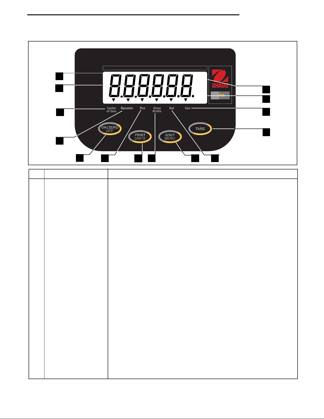
OVERVIEW OF CONTROLS AND INDICATOR FUNCTIONS
14
1
*
lb
oz
kg
BAT
C
W
CW-11 Indicator
13
12
2
3
4
No. Designation Function
1 Display LCD display, indicates weight, modes and setup information.
2 Center of Zero LCD indicator prompt, indicates center of zero when within +/- 0.25d.
3 Dynamic LCD indicator prompt, indicates that Indicator is in dynamic weighing mode.
4 ON/ZERO/OFF button Turns Indicator on or off. Secondary use, provides zero function.
5 Pcs LCD indicator prompt, indicates parts counting function.
6 Print/Units button Short press, prints data which is displayed on the Indicator.
5
Long press, changes unit of measure.
When in menus, each press advances horizontally through the menus.
Finalizes a menu selection.
6
7
8
9
11
10
7 Gross Brutto LCD indicator prompt, indicates gross weight.
8 G/N/T/Menu button Recalls Gross/Net/Tare. Long press allows entry into menus. When in
menus, advances through individual menu items.
9 Net LCD indicator prompt indicates net weight.
10 Tare button When pressed, enters tare value into memory.
11 Tare LCD indicator prompt indicates tare weight.
12 kg LCD indicator, when lit, indicates weight in kilograms.
g LCD indicator, when lit, indicates weight in grams.
13 lb LCD indicator, when lit, indicates weight in pounds.
oz LCD indicator, when lit, indicates weight in ounces.
14 * Stability indicator, when lit, indicates stable weight.
3
Page 7

CW-11 Indicator
1. GETTING TO KNOW YOUR INDICATOR
1.1Introduction
Thank you for deciding to purchase a CW-11 Indicator from Ohaus. The Ohaus CW-11 Indicator is a rugged,
reliable, electronic weight indicator in an IP65 washdown enclosure designed for easy operation in washdown
applications. The CW-11 Indicator can drive up to four 350 ohm load cells and provides capacity selections
up to 20,000 lb/kg with a maximum resolution of 1:20,000.
The CW-11 operates from AC power and can also be powered by six Alkaline C batteries internally. A six digit
LCD display is 1.0 inches/2.5 centimeters in height provides easy visibility when working at distances from the
indicator. Four switches mounted on the front panel enable simple set up procedures. A menu lockout switch
can be set to lock out various functions of the indicator to prevent settings from being changed. An RS232
Interface is built in. An adjustable mounting bracket permits the Indicator to be installed on a table or wall.
Behind your instrument stands OHAUS, a leading manufacturer of precision Indicators, Scales and Balances.
An Aftermarket Department with trained instrument technicians is dedicated to providing you with the fastest
service possible in the event your instrument requires servicing. OHAUS also has a Customer Service Department to answer any inquiries regarding applications and accessories.
To ensure you make full use of the possibilities offered by your CW-11 Indicator, please read the manual
completely before installation and operation.
1.1.1 Features
Major features include:
6 digits, 7-segments, 25 mm Numeric LCD display
4 membrane switches
Supports up to four (4) 350 ohm analog load cells
Suitable for 2mV/V and 3mV/V load cell with no jumper
Up to 20,000d display resolution
Push-button Tare/Clear
Flexible unit switching-lb/kg/oz/g
Enhanced digital filtering
Overload/Underzero display indication
3-wire RS232 Serial Communication in Ohaus RS-Interface
Up to 100 hours continuous battery operation with one 350 load cell
AC & DC power supply
Low - BAT warning comes on 20 minutes prior to low power point
Auto shut off for power saving
IP65 washdown SS enclosure
Either Animal weighing or parts counting function
4
Page 8

CW-11 Indicator
2. INSTALLATION
2.1 Unpacking and Checking
Open the package and remove the instrument and the accessories. Check the completeness of the delivery. The
following accessories are part of the standard equipment of your new Indicator.
Remove packing material from the instrument.
Check the instrument for transport damage. Immediately inform your Ohaus dealer if you have complaints or
parts are missing. Your Indicator package should contain:
Indicator CW-11
Warranty card
Capacity label
Screw driver for terminal connections
Instruction Manual
lead seal for weights and measures sealing
Store all parts of the packaging. This packaging guarantees the best possible protection for the transport of your
instrument.
2.2 Selecting the Location
The Indicator should be used in an environment which is free from corrosives, vibration or temperature extremes.
These factors will affect displayed weight readings. Scale bases used with the Indicator should be located on a
stable level surface and kept away from vibrating sources such as large machinery. Maximum accuracy will be
achieved when the area is clean and vibration free.
2.3 Connecting the Indicator to a Scale Base
At the bottom of the back cover of the Indicator are two slots. There is a spring clip at each slot location which
holds the cover in place. Insert the small scewdriver blade into each slot and press and work the back cover
off. With the cover removed, proceed as follows:
Remove the rear cover. Inside is the battery compartment which is wired to the PC board underneath.
Remove batteries if installed.
Remove the four corner screws from the battery board. One of the screws is crossed drilled to accept a wire seal
when used for legal for trade applications.
Carefully lift the battery board up and out of the indicator. The wires can be disconnected from the main PC
board by unplugging the connector.
Pass the load cell cable through the large or small liquid tight connector on the bottom of the housing. (Depending on cable size.)
5
Page 9
CW-11 Indicator
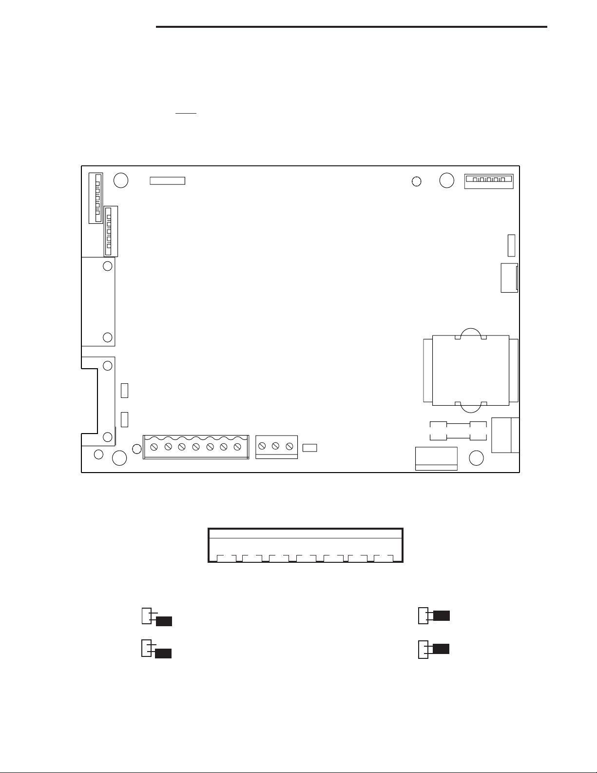
2.3 Connecting the Indicator to a Scale Base (Cont.)
Refer to the color code of the load cell cable and connect the wires to Terminal Strip J4. Tighten all screws
securely. The connections are shown for a 6 wire cable. When a 4 wire cable is used, the Jump 1 and Jump
2 jumpers on the PC board
For obtaining better performance, it is recommended to keep both JUMP 1 and JUMP 2 jumpers open when a
6-wire load cell is connected to the CW-11.
J5A
1
J5B
5
J2
1
6
J1
5
must be positioned as shown in the illustrations below.
15
CW11 MAIN BOARD
J5
5
1
J6
3
2
J7
4
1
9
5
J3
5
JUMP 1
6
1
JUMP 2
1
9
1
17
+EXE +SEN
J4
+SIG
CGND -SIG -SEN -EXE
J10
1
TXD RXD GND
3
CAL
T1
50m
A
250V
1
J9 3
NEUT 110V 220V
3
J8
0V
2
2
V
0
1
1
T
U
E
N
1
Printed Circuit Board Connector Locations.
12 3 4 5 6 7
J4
+EXE +SEN +SIG CGND -SIG -SEN -EXE
Connector J4 Terminations.
J3
6-Wire Jumper Connections.
4-Wire Jumper Connections.
J3
6
Page 10

CW-11 Indicator
2.4 Communication Connections
Provisions are made in the Indicator to communicate with an external computer or printer using an RS232
protocol. To connect, proceed as follows:
Pass the communication cable through one of the liquid seal connectors at the bottom of the Indicator.
Connect the cable to the J10 connector on the PC board. Observe the functions and connect correctly.
Connect the opposite end of the cable to the device.
After all connections have been made to the main PC board, replace the battery cover and lightly secure with
the four screws previously removed. If the Indicator is to be used in a legal for trade application, you will have
to gain access to the legal for trade switch on the main PC board again after all Indicator settings have been
made. Once this is done, the rear cover can be replaced.
2.5 Cautionary Notes
Model CW-11 Indicator must not be operated in hazardous areas.
Before connecting AC power, verify that the Indicator operating voltage corresponds to the local mains voltage.
If this is not the case, check terminal board J9 connections on the main PC board. There are provisions for
110V or 220V operation. Please contact your local Ohaus dealer if the voltages do not match.
Model CW-11 Indicator may be used in a washdown environment.
The CW-11 Indicator may be operated using the AC power cord , or 6 Alkaline C-type batteries (not supplied).
When the Indicator is plugged into a power source, the batteries are automatically disconnected. In the event
of a power failure, the batteries if installed will automatically continue to operate the balance.
2.6 Connecting Power
2.6.1 Battery Installation
With the back cover removed from the Indicator, insert 6 Alkaline C-type batteries into the battery holder
making sure that the batteries are properly orientated (correct polarity).
NOTE: It is recommended that when the CW-11 is operated from batteries, the Auto-Off Timer feature be
turned on to extend battery life. When setting up the Indicator, refer to Intial Setup,Readout menu,
paragraph 2.8.5.
2.6.2 AC Power
Connect the AC power cord from the Indicator and plug into a convenient power outlet.
NOTICE:
The socket/outlet must be installed near
the equipment and shall be easily accessible.
7
Page 11

CW-11 Indicator
2.6.3 Operating the Indicator
Once the Indicator and Scale Base are connected and installed, follow the setup procedure outlined below.
Power On/Off
With the Indicator connected to an appropriate power supply, press the ON/ZERO/OFF button. The Indicator
performs a self-test, indicates the software revision momentarily and then goes to a weighing mode. At this
point, the Indicator is on and ready for initial setup.
Stabilization
Before initially using the Indicator, allow time for it to adjust to its new environment. Recommended warm up
period is five (5) minutes.
2.7 Setup Protection
The CW-11 Indicator is equipped with menus which permit certain functions to be locked out (not changed)
during operation. If you intend to lock out changes to the setup selections you make, do not re-assemble the
indicator. You will need to access the cal jumper located on the main PC circuit board following the setup
procedure.
2.8 Initial Setup
For first time setup, step through all menus and set the parameters as desired. As the last step, enter the CAL
menu and calibrate the system.
The indicator has five menus; CAL, SETUP, READ, PRINT and LOCSW which are entered by pressing and holding
the G/N/T/MENU button until MENU is displayed, then releasing it. The display then switches to CAL. To access
the rest of the menus, the PRINT/UNITS button is repeatedly pressed until the desired menu is reached.
2.8.1 Control Functions
During setup, only the PRINT/UNITS and G/N/T/MENU buttons are used.
PRINT/UNITS Button
Change between menus horizontally or change sub-menu parameters.
G/N/T/MENU Button
Press and hold to enter menu. Enters menu and steps through sub-menus vertically.
8
Page 12
0
0
0
0
0
0
0
0
0
0
0
0
0
0
0
0
0
0
0
0
0
0
0
0
0
0
0
0
0
0
0
0
1
1
1
1
1
1
1
1
1
1
1
1
1
1
1
1
1
1
1
1
1
1
1
1
1
1
1
1
1
1
1
1
1
1
1
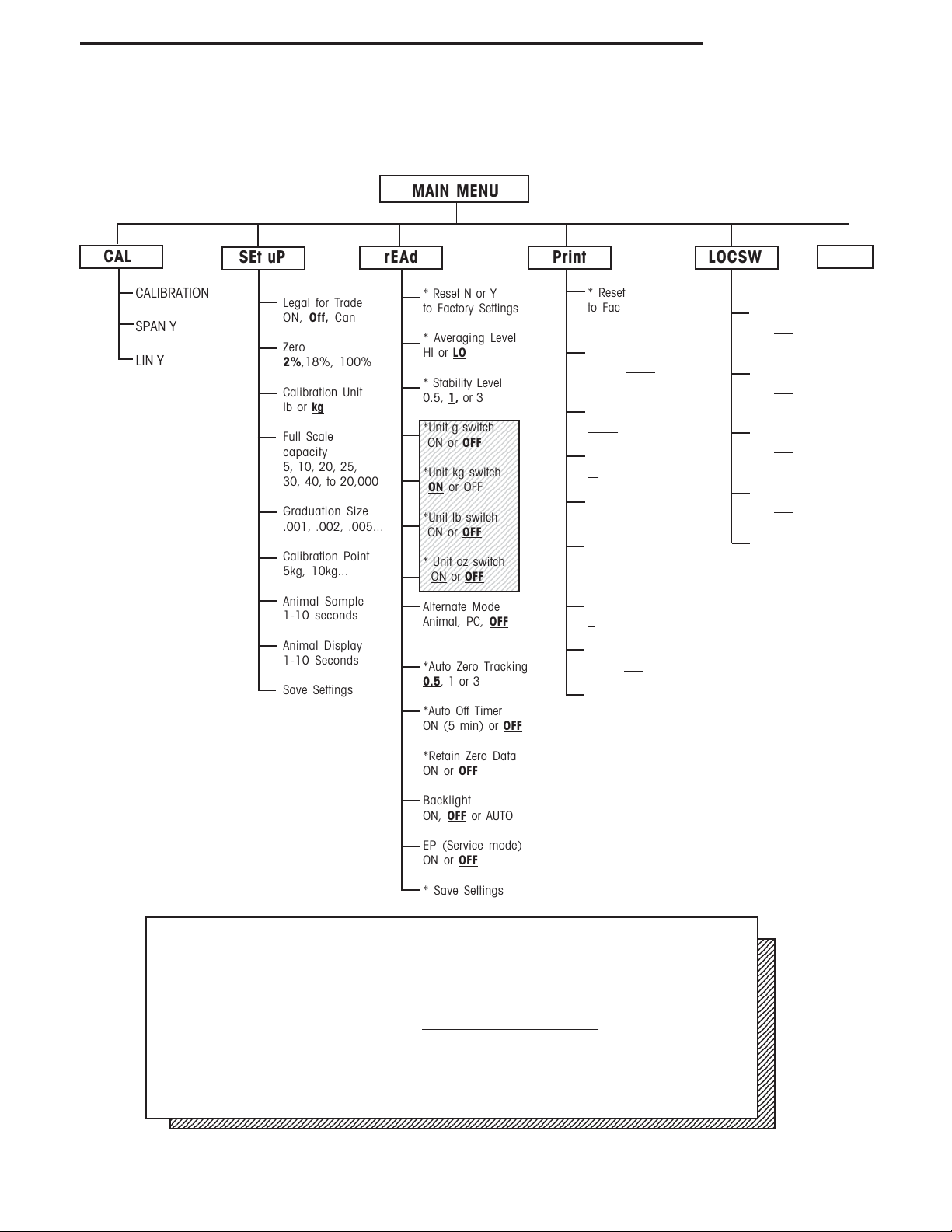
2.8.2 Menu Structure
The following table illustrates the menu structure in the CW-11 Indicator.
MAIN MENU
CW-11 Indicator
CAL
CALIBRATION
SPAN Y
LIN Y
SEt uP rEAd Print LOCSW
Legal for Trade
Off, Can
ON,
Zero
2%,18%, 100%
Calibration Unit
lb or
kg
Full Scale
capacity
5, 10, 20, 25,
30, 40, to 20,000
Graduation Size
.001, .002, .005...
Calibration Point
5kg, 10kg...
Animal Sample
1-10 seconds
Animal Display
1-10 Seconds
Save Settings
* Reset N or Y
to Factory Settings
* Averaging Level
HI or
LO
* Stability Level
0.5,
1, or 3
234567890123456789
234567890123456789
*Unit g switch
234567890123456789
234567890123456789
234567890123456789
ON or
OFF
234567890123456789
234567890123456789
234567890123456789
234567890123456789
234567890123456789
234567890123456789
*Unit kg switch
234567890123456789
234567890123456789
234567890123456789
ON or OFF
234567890123456789
234567890123456789
234567890123456789
234567890123456789
234567890123456789
234567890123456789
*Unit lb switch
234567890123456789
234567890123456789
ON or
OFF
234567890123456789
234567890123456789
234567890123456789
234567890123456789
234567890123456789
234567890123456789
* Unit oz switch
234567890123456789
234567890123456789
234567890123456789
ON or OFF
234567890123456789
Alternate Mode
Animal, PC,
OFF
*Auto Zero Tracking
0.5, 1 or 3
*Auto Off Timer
ON (5 min) or
OFF
* Reset
to Factory Settings
Yes or No
* Baud Rate set
1200,
2400, 4800
9600, 19,200
*Parity Bit set
NONE, Even, or Odd
*Data Length set
7 or 8
*Stop Bits set
1 or 2
Auto Print
ON,
OFF, cont,
Interval, On Stability
Interval
1 to 3600 seconds
Stable
ON or
OFF
* Save Settings
Quit
SETUP Lock
Switch set
ON,
OFF
* READOUT
Lockout Switch set
ON,
OFF
* PRINT Lockout
Switch set
ON,
OFF
CALIBRATION
Lockout Switch set
ON,
OFF
* Save Settings
NOTE: For details about units in shaded
area, refer to paragraph 4.7.
Press (G/N/T/MENU) to enter the display submenu or select a displayed setting.
2345678901234567890123456789012123456789012345678901234567890121234567890123456789012345678901212345678901234567890
2345678901234567890123456789012123456789012345678901234567890121234567890123456789012345678901212345678901234567890
2345678901234567890123456789012123456789012345678901234567890121234567890123456789012345678901212345678901234567890
2345678901234567890123456789012123456789012345678901234567890121234567890123456789012345678901212345678901234567890
2345678901234567890123456789012123456789012345678901234567890121234567890123456789012345678901212345678901234567890
2345678901234567890123456789012123456789012345678901234567890121234567890123456789012345678901212345678901234567890
2345678901234567890123456789012123456789012345678901234567890121234567890123456789012345678901212345678901234567890
2345678901234567890123456789012123456789012345678901234567890121234567890123456789012345678901212345678901234567890
Press (PRINT/UNITS) to change the displayed submenu or setting.
2345678901234567890123456789012123456789012345678901234567890121234567890123456789012345678901212345678901234567890
2345678901234567890123456789012123456789012345678901234567890121234567890123456789012345678901212345678901234567890
2345678901234567890123456789012123456789012345678901234567890121234567890123456789012345678901212345678901234567890
2345678901234567890123456789012123456789012345678901234567890121234567890123456789012345678901212345678901234567890
2345678901234567890123456789012123456789012345678901234567890121234567890123456789012345678901212345678901234567890
2345678901234567890123456789012123456789012345678901234567890121234567890123456789012345678901212345678901234567890
2345678901234567890123456789012123456789012345678901234567890121234567890123456789012345678901212345678901234567890
2345678901234567890123456789012123456789012345678901234567890121234567890123456789012345678901212345678901234567890
2345678901234567890123456789012123456789012345678901234567890121234567890123456789012345678901212345678901234567890
Factory default settings are shown in
2345678901234567890123456789012123456789012345678901234567890121234567890123456789012345678901212345678901234567890
2345678901234567890123456789012123456789012345678901234567890121234567890123456789012345678901212345678901234567890
2345678901234567890123456789012123456789012345678901234567890121234567890123456789012345678901212345678901234567890
2345678901234567890123456789012123456789012345678901234567890121234567890123456789012345678901212345678901234567890
2345678901234567890123456789012123456789012345678901234567890121234567890123456789012345678901212345678901234567890
2345678901234567890123456789012123456789012345678901234567890121234567890123456789012345678901212345678901234567890
2345678901234567890123456789012123456789012345678901234567890121234567890123456789012345678901212345678901234567890
2345678901234567890123456789012123456789012345678901234567890121234567890123456789012345678901212345678901234567890
When jumper (CAL) on the circuit board is opened, all of the menus can be reached
2345678901234567890123456789012123456789012345678901234567890121234567890123456789012345678901212345678901234567890
2345678901234567890123456789012123456789012345678901234567890121234567890123456789012345678901212345678901234567890
2345678901234567890123456789012123456789012345678901234567890121234567890123456789012345678901212345678901234567890
2345678901234567890123456789012123456789012345678901234567890121234567890123456789012345678901212345678901234567890
except CALIBRATION Menu, but only the submenus which are marked ' * ' can be
2345678901234567890123456789012123456789012345678901234567890121234567890123456789012345678901212345678901234567890
2345678901234567890123456789012123456789012345678901234567890121234567890123456789012345678901212345678901234567890
2345678901234567890123456789012123456789012345678901234567890121234567890123456789012345678901212345678901234567890
2345678901234567890123456789012123456789012345678901234567890121234567890123456789012345678901212345678901234567890
setup, see menu structure.
2345678901234567890123456789012123456789012345678901234567890121234567890123456789012345678901212345678901234567890
2345678901234567890123456789012123456789012345678901234567890121234567890123456789012345678901212345678901234567890
*Retain Zero Data
ON or
OFF
Backlight
ON,
OFF or AUTO
EP (Service mode)
ON or
OFF
* Save Settings
underlined and boldface type.
9
Page 13

CW-11 Indicator
2.8 Initial Setup (Cont.)
2.8.3Load Cell Capacity Information
Review the specifications of the scale base to be used with the Indicator. Make sure the settings you select in the
indicator are compatible with the scale base. Below is a Load Cell Scale Capacity (lb or kg) table. Use this table
to determine the settings of the Indicator based on the capacity and resolution of the scale base.
Grad
1000d 1200d 1500d 2000d 2500d 3000d 4000d 5000d 6000d 7500d 10000d 20000d 12500d 15000d
0.001 - - - 2 - 3 - 5 - - 10 20 - 15
0.002 - - - 4 - 6 - 10 - 15 20 40 25 30
0.005 5 - - 10 - 15 20 20 30 - 50 100 - 75
0.01 10 - - 20 25 30 40 50 60 75 100 200 - 150
0.02 20 - 30 40 50 60 - 100 120 150 200 400 250 300
0.05 50 60 75 100 - 150 200 250 300 - 500 1000 - 750
0.1 100 120 150 200 250 300 400 500 600 750 1000 2000 - 1500
0.2 200 - 300 400 500 600 - 1000 - 1500 2000 - 2500 3000
0.5 500 600 750 1000 - 1500 2000 2500 3000 - 5000 10000 - 7500
1 1000 1200 1500 2000 2500 3000 - 5000 - 7500 10000 20000 - 2 2000 - 3000 - 5000 - - 10000 - - 20000 - - 5 5000 - 7500 10000 - - 20000 - - - - - - -
LOAD CELL SCALE CAPACITIES (LB OR Kg)
10
Page 14

CW-11 Indicator
2.8 Initial Setup (Cont.)
2.8.4 Setup Menu
The CW-11 Indicator Setup Menu must be entered the first time the Indicator is used to set the scale base
parameters to match the Indicator. Do not attempt to calibrate the Indicator before setting up the Setup
Menu. All other menus should be entered and set up the first time the Indicator is used.
Procedure
With the Indicator ON, press and hold the G/N/T/
MENU button until MENU is displayed. When you
release G/N/T/MENU button, CAL is displayed when
the CAL jumper on the PC board is in place. When
the CAL jumper is removed, the Indicator will not
permitcalibration. This jumper should be in place
initially.
Press PRINT/UNITS button, SETuP is displayed.
Press G/N/T/MENU button, LFTOFF is displayed.
legal for trade selections are:
'LFT ON' - LFT is ON
'LFTOFF' - LFT is OFF
'LFTCAn' - LFT is set for Canada
kg
Press PRINT/UNITS button and select either ON ,
OFF or Canada.
Press G/N/T/MENU button, 0 2 is displayed. This
is the Zero 2%, 18% or 100% setting. 2% - zero
operation range is - 2% to + 2%. 18% - zero
operating range is -2% to +18%, 100% - zero
operation range is -2% to +100%.
NOTE: If LFT is ON, only 2% and 18% are available.
Press PRINT/UNITS button, and select either 2%,
18% or 100%.
Press G/N/T/MENU button, CAL Un kg is displayed.
This is the calibration unit setting. Selections are:
'lb' - calibration unit is lb
'kg' - calibration unit is kg.
Press PRINT/UNITS button, and select either kg or lb.
11
Page 15

CW-11 Indicator
2.8 Initial Setup (Cont.)
2.8.4 Setup Menu (Cont.)
kg
kg
Press G/N/T/MENU, F xx is displayed. This is full
scale capacity selections. xx= value last set.
Selections are:
5, 10, 15, 20, 25, 30, 40, 50, 60, 75, 100, 120,
150, 200, 250, 300, 400, 500, 600, 750, 1000,
1200, 1500, 2000, 2500, 3000, 5000, 7500,
10000, 20000 (lb or kg).
Press PRINT/UNITS button until desired capacity
value is reached.
Press G/N/T/MENU button, Gd0.01 is displayed.
This is the graduation size. Refer to paragraph
2.8.3 Load Cell Capacity Information table. For
available selections, press PRINT/UNITS button until
desired graduation value is reached.
kg
Press G/N/T/MENU button, CP 30 kg is displayed.
This is the full scale calibration point setting. The
range is from 20% to 100% Full scale capacity.
Press PRINT/UNITS button until desired calibration
value is reached.
Press G/N/T/MENU button, AS 3 is displayed. This
is the duration of animal sample time which can be
set from 1 to 10 seconds.
Press PRINT/UNITS button until desired sample time
value is reached. See Note below.
Press G/N/T/MENU button, Ad 4 is displayed. This
is the duration of animal weighing display time
which can be set from 1 to 10 seconds. The default
is 10 seconds. See Note below.
Press PRINT/UNITS button until desired sample time
value is reached. See Note below.
Press G/N/T/MENU button to end this block, SAVE is
displayed.
Press G/N/T/MENU button, rEAD is displayed which
is the next menu or press PRINT/UNITS button to
return to Setup menu.
12
The Indicator is now matched up with the scale
base and the Indicator parameters may now be set
and calibrated.
NOTE: Not available if LFT is ON. Only available if ALT
is set to ANI.
Page 16

CW-11 Indicator
2.8 Initial Setup (Cont.)
2.8.5 Readout Menu
The Readout menu is used to adapt the Indicator to environmental conditions, set measuring units on/off, alternate modes - animal weighing & parts counting, auto zero tracking, timer on/off, retain zero data and backlighting. Review all of the settings available before proceeding.
Procedure
To select any of the items in the Readout menu,
proceed as follows: NOTE: If you have entered from
the preceeding menu, disregard the first step.
With the Indicator ON, press and hold the G/N/T/
MENU button until MENU is displayed. When you
release the G/N/T/MENU button, CAL is displayed,
then press PRINT/UNITS button, until rEAd is displayed.
Press G/N/T/MENU button, rESETn is displayed.
This allows resetting the readout menu to factory
defaults. rESETn = no and does not reset settings.
rESETy= yes and will reset the entire readout menu
as follows: AL Lo, StAb 1, Un Off g, Un On kg, Un Off,
lb, Un Off oz, Alternate Mode Off, AZt 0.5, Aot Off, rZd
Off and Backlight auto.
Press PRINT/UNITS button,and select N or Y.
AVERAGING LEVEL
Averaging level compensates for vibration or excessive air currents on the scale base. During operation,
the indicator continually takes weight readings from
the load cell. Successive readings are then digitally
processed to achieve a stabilized display. Using this
feature, you specify how much processing you need.
HI and LO settings are available.
HI setting:
More processing, greater stability and
slower stabilization time.
LO setting:
Less processing, less stability and faster
stabilization time.
13
Page 17

CW-11 Indicator
2.8 Initial Setup (Cont.)
2.8.5 Readout Menu (Cont.)
Procedure
AVERAGING LEVEL (Cont.)
Press G/N/T/MENU button, AL LO is displayed. This is
averaging level settings. Selections are:
'Lo' - Averaging level is low
'Hi' - Averaging level is high.
Press PRINT/UNITS button,and select LO or HI.
STABILITY
The stability range specifies the weighing results and
must be within a preset tolerance limit for a certain
time to turn the stability indicator ON. When a displayed weight changes beyond the allowable range,
the stability indicator turns OFF, indicating an unstable
condition. Factory default setting is shown in bold
type.
.5d Smallest range: stability indicator is
ON only when displayed weight is
within .5 divisions.
1d Normal setting. - Fixed for LFT
3d More stable course
Press G/N/T/MENU button, StAb1 is displayed.The
stability range specifies the weighing results and
mustbe within a preset tolerance limit for a certain
time to turn the stability indicator ON. When a
displayed weight changes beyond the allowable
range, the stability indicator turns OFF, indicating an
unstable condition. 0.5 d smallest range, stability
indicator is ON only when displayed weight is stable
within 0.5 divisions. 1 d-stable within 1 division. 3
d-largest range, stability indicator is ON even
though displayed weight changes 3 divisions.
Factory default setting is 1.
Press PRINT/UNITS button,and select 0.5, 1, or 3.
Normal 1d stability is default/recommended.
14
Page 18

2.8 Initial Setup (Cont.)
2.8.5 Readout Menu (Cont.)
CW-11 Indicator
Procedure
UNITS SELECTION
Press G/N/T/MENU button, Un OFF g is displayed.
g
lb
kg
oz
Press PRINT/UNITS button, and select ON or OFF.
OFF is the default setting.
Press G/N/T/MENU button, Un ON lb is displayed.
This is unit pounds which can be turned ON or OFF.
This will be displayed when CAL UNIT kg was
selected. When lb was selected as calibration unit,
kg will display.
Press PRINT/UNITS button,and select ON or OFF.
ON is the default setting.
Press G/N/T/MENU button, Un OFF oz is displayed.
This unit is ounces which can be turned ON or OFF.
Default setting is OFF.
Press PRINT/UNITS button,and select ON or OFF.
NOTE: If CAL Unit is kg, then UNIT kg is fixed to ON
menu not shown. The same if CAL Unit is set to lb.
ALTERNATE MODE - Not available if LFT is ON.
Press G/N/T/MENU button, ALtOFF is displayed.
This enables either animal weighing or simple parts
counting functions. The alternate mode can be
turned off so that neither mode is available. It is not
possible to have both modes activated at the same
time.
Press PRINT/UNITS button, and select either OFF,
ALtAn i (animal) or ALt PC (parts counting). OFF is
the default setting.
15
Page 19

CW-11 Indicator
2.8 Initial Setup (Cont.)
2.8.5 Readout Menu (Cont.)
AUTO ZERO
Press G/N/T/MENU button, AZt 0.5 is displayed.
This is the Auto Zero Threshold setting. Auto Zero
minimizes the effects of temperature changes and
small disturbances on the zero reading. The
Indicator maintains the zero display until the threshold is exceeded. Settings are shown as follows:
OFF
0.5d Sets threshold to 0.5 divisions. - Fixed in LFT
1d Sets threshold to 1 division.
3d Sets threshold to 3 divisions.
Factory default setting is 0.5d.
Press PRINT/UNITS button,and select either 0.5, 1 or
3.
AUTO POWER OFF
Press G/N/T/MENU button, AOtOFF is displayed. This
is the Auto Off Timer. When set ON, the Indicator will
shut off automatically after 5 minutes has elapsed
based on the condition that no button is pressed
and the scale base is stable during that period.
Press G/N/T/MENU button,and select ON or OFF.
OFF is the default setting.
RETAIN ZERO DATA
Press G/N/T/MENU button, Un rZdOFFis displayed.
This is Retain Zero Data which can be turned on or
off. When set On, the Indicator stores the current
zero point and restores it on the power-up.
Press PRINT/UNITS button, and select ON or OFF.
OFF is the default setting.
16
Page 20

2.8 Initial Setup (Cont.)
2.8.5 Readout Menu (Cont.)
CW-11 Indicator
LCD BACK LIGHT
Press G/N/T/MENU button, bLAutOis displayed. You
can select to have the LCD backlight either on
contiuously, off or in an automatic mode which
turns off the display in 5 seconds.
Press PRINT/UNITS button, and either select ON, OFF
or Auto. Auto is the default setting.
EP
This is service function and is not a user operated
command. OFF is the default setting.
Not available w/LFT ON.
SAVE
Press G/N/T/MENU button to end this block, SAVE is
displayed. All settings are retained.
Press G/N/T/MENU button, setting are saved and
PRINT is displayed which is the next menu or press
PRINT/UNITS button to go back to Setup menu
without saving.
NOTE:(If initial setup, go to the next paragraph. To
exit from the Setup, press PRINT/UNITS button to
skip to PRINT then to LOCKSW, then QUIT. Press
G/N/T/MENU button to go back to the weighing
mode).
17
Page 21

CW-11 Indicator
2.8 Initial Scale Setup (Cont.)
2.8.6 Print Menu
The Print menu provides data communication settings which can be entered. It contains 9 submenus: Reset,
Baud rate, Parity Bit, Data Length, Stop Bits, Auto Print, Interval, Stable and Save.
Procedure
PRINT
To select any of the items in the Print menu, proceed
as follows: NOTE: If you have entered from the
preceeding menu, disregard the first step.
With the Indicator ON, press and hold the G/N/T/
MENU button until MENU is displayed. When you
release the G/N/T/MENU button, CAL is displayed,
then press PRINT/UNITS button, until Print is displayed.
RESET
Press G/N/T/MENU button, rESEtn is displayed. This
allows resetting the Print menu to factory defaults.
rESETn = no does not reset settings. rESETy= yes
will reset the entire Print menu as follows:
Baud rate =2400, parity =none, data length=7,
stop bit=2.
Press PRINT/UNITS button, and select N or Y.
BAUD RATE
Press G/N/T/MENU button, bd2400 displayed.
Press PRINT/UNITS button, and select desired baud
rate. Baud rate selections are: 1200, 2400, 4800
9600 and 19200. 2400 is the default setting.
PARITY
Press G/N/T/MENU button, PAr NO is displayed.
This is the parity bit.
18
Press PRINT/UNITS button, and select desired parity
of NO=none, Odd=odd, E=even. Default setting is
none.
Page 22

2.8 Initial Scale Setup (Cont.)
2.8.6 Print Menu (Cont.)
CW-11 Indicator
Procedure (Cont.)
DATA
Press G/N/T/MENU button, dAtA 7 is displayed.
This is the data length.
Press PRINT/UNITS button, and select desired data
length of 7 or 8. Default setting is 7.
STOP BITS
Press G/N/T/MENU button, StOP 2 is displayed. This
is the stop bit.
Press PRINT/UNITS button, and select desired stop
bit of 1 or 2. Default setting is 2.
AUTO PRINT
Auto print has settings which enables data to a printer
or PC to be set Off, run continuously, at selected preset
intervals or on stability. On stability will print first stable
non-zero value after each change in weighing value.
Press G/N/T/MENU button, AP OFF is displayed.
Press PRINT/UNITS button, and select either Off,
Continous, Interval or On Stability. Default setting is
OFF.
INTERVAL - PRINTING
When interval has been selected in the previous step,
you may now set an interval from 1 to 3600 seconds.
Press G/N/T/MENU button, int is displayed, after a
few seconds, a second display appears which
allows you to set in the time in seconds.
Pressing the PRINT/UNITS button advances the zero
from left to right. Sample at left indicates 10 seconds.
NOTE: 0000 not valid.
19
Page 23

CW-11 Indicator
2.8 Initial Scale Setup (Cont.)
2.8.6 Print Menu (Cont.)
INTERVAL - PRINTING (Cont.)
Pressing the TARE button increments the digit from 1
to 0. When the desired number of seconds have
been entered, press the G/N/T/MENU button. Stb
OFF is displayed.
STABLE
When set ON, allows only stable weight values to be
printed. When set OFF, prints immediate value with an
indication of stability. In LFT, fixed to ON.
With Stb OFF displayed, press PRINT/UNITS button,
and select ON or OFF. Default setting is OFF.
SAVE
Press G/N/T/MENU button to end this block, SAVE is
displayed. All settings are retained.
Press G/N/T/MENU button to save settings, LOCSW
is displayed which isthe next menu or press PRINT/
UNITS button to go back to Read menu without
saving.
NOTE:(If initial setup, go to the next paragraph. To
exit from the Setup, press PRINT/UNITS button to
skip to LOCKSW, then QUIT. Press G/N/T/MENU
button to go back to the weighing mode).
2.8 Initial Scale Setup (Cont.)
2.8.7 Lockout Switch Menu
Lockout Switch menu (LOCSW) is a software controlled option which can lock the settings in the Calibration,
Setup, Readout, and Print menus to prevent tampering. When used in conjunction with the Lock Switch
(jumper) on the printed circuit board, the Calibration, Setup, Readout and Print menus can be read only and
not changed by an operator or the jumper can be left in place and the LOCSW menu is used to prevent accidental changes..
Procedure
To select any of the items in the Lockswitch menu,
proceed as follows: NOTE: If you have entered from
the preceeding menu, disregard the first step.
20
Page 24

2.8 Initial Scale Setup (Cont.)
2.8.7 Lockout Switch Menu (Cont.)
CW-11 Indicator
Procedure (Cont.)
With the Indicator ON, press and hold the G/N/T/
MENU button until MENU is displayed. When you
release the G/N/T/MENU button, CAL is displayed,
then press PRINT/UNITS button, until LOCSW is
displayed.
Press G/N/T/MENU button, LSTOFF is displayed.
This permits locking the Setup menu. OFF is unlocked, ON is read only (locked). This menu is
hidden if the CAL jumper is off.
Press PRINT/UNITS button, and select ON or OFF.
Press G/N/T/MENU button, LrdOFF displayed. This
permits locking the Readout menu. OFF is unlocked, ON is read only (locked).
Press PRINT/UNITS button, and select ON or OFF.
Press G/N/T/MENU button, LPtOFF is displayed.
This permits locking the Print menu. OFF is unlocked, ON is read only (locked).
Press PRINT/UNITS button, and select ON or OFF.
Press G/N/T/MENU button, LCLOFF is displayed.
This permits locking the Calibration menu. OFF is
unlocked, ON is read only (locked). This menu is
hidden if the CAL jumper is off.
Press PRINT/UNITS button, and select ON or OFF.
Press G/N/T/MENU button to end this block, SAVE
is displayed.
Press G/N/T/MENU , Quit is displayed..
Press PRINT/UNITS button to go to CAL or press
G/N/T/MENU button, Indicator returns to a weighing
mode.
Center
of Zero
Gross
Brutto
kg
NOTE: At this point, the Indicator must be calibrated
and the jumper removed from the CAL connector in
order to lock out the menus. The top cover of the
Indicator should be free to gain access to the CAL
jumper.
21
Page 25

CW-11 Indicator
3. CALIBRATION AND SEALING
Model CW-11 Indicator requires span calibration before using. Span calibration ensures that the Indicator
reads correctly within specifications using weight values from about 20% to 100% of capacity. For best
results, calibrate at or near full capacity. Calibration unit can be set to either kg or lb.
NOTE: When the Indicator is used in Legal for trade applications, the calibration menu is locked out and
is not accessable. This is to prevent unauthorized personnel from changing calibration. Before beginning
calibration, make sure masses are available. If you begin calibration and realize calibration masses are not
available, exit the menu. The Indicator will retain previously stored calibration data. Calibration should be
performed as necessary to ensure accurate weighing. Masses required to perform the procedures should be
in compliance with the requirements of the scale base being used with the Indicator. You have a choice of
either span or linearity calibration. Span calibration checks zero and full span calibration points. Linearity
calibration checks zero, mid span and full span points.
Procedure
SPAN CALIBRATION
With the Indicator ON, press and hold the button
G/N/T/MENU until MENU is displayed. When you
release the G/N/T/MENU button, CAL is displayed.
Press G/N/T/MENU button, SPAN Y is displayed.
Press G/N/T/MENU button, -C- is displayed. The
scale base MUST be stable during this period and is
establishing a zero point. After a few seconds, the
requested weight value is displayed. The sample illustration indicates a 10kg scale. (Cal Point CP
was set for 10kg)
kg
Place the indicated mass on the platform. Keep the
platform stable during this period.
Press G/N/T/MENU button, -C- is displayed while
the Indicator stores the reading and then displays
the weight of the mass.
*
kg
Gross
Brutto
If the calibration was successful, the calibration
mass is displayed and the calibration data is saved
automatically. If unsuccessful, refer to the troubleshooting section.
Remove calibration masses from platform.
NOTE: If the Indicator is to be used for legal for trade applications, it must be calibrated and the jumper removed
from the CAL connector in order to lock out the menus. The top cover of the Indicator should be free to gain
access to the CAL jumper. Refer to paragraph 3.1 for sealing for legal for trade use.
22
Page 26

3. CALIBRATION AND SEALING (Cont.)
CW-11 Indicator
Procedure
LINEARITY CALIBRATION
With the Indicator ON, press and hold the button
G/N/T/MENU until MENU is displayed. When you
release the G/N/T/MENU button, CAL is displayed.
Press G/N/T/MENU button, SPAN Y is displayed.
Press PRINT/UNITS button, Lin Y is displayed.
Press G/N/T/MENU button, -C- is displayed. The
scale base MUST be stable during this period and is
establishing a zero point. After a few seconds, the
display flashes LIN CP twice and the requested
weight value is displayed. The sample illustration
indicates a 5kg center point for a 10kg scale..
Place the indicated mass on the platform. Keep the
platform stable during this period.
kg
Press G/N/T/MENU button, -C- is displayed. The
scale base MUST be stable during this period and is
establishing a zero point. After a few seconds, the
display flashes FULLCP twice and the requested
weight value is displayed.
Place the indicated mass on the platform and press
*
kg
the G/N/T/MENU button -C- is displayed.
If linearity calibration was successful, the calibration
mass is displayed and the calibration data is saved
automatically. If unsuccessful, refer to the troubleshooting section.
*
Remove calibration masses from platform.
Gross
Brutto
kg
NOTE: If the Indicator is to be used for legal for trade applications, it must be calibrated and the jumper removed from the CAL connector in order to lock out the menus. The top cover of the Indicator should be free to
gain access to the CAL jumper. Refer to paragraph 3.1 for sealing for legal for trade use.
23
Page 27

CW-11 Indicator
3.1 Legal for Trade (LFT) Operation and LFT Sealing
Before this product can be used in legal-for-trade or legally controlled applications, it must be inspected in
accordance with local weights and measures or approval agency regulations. It is the responsibility of the
purchaser to ensure that all pertinent legal requirements are met. Please contact your local weights and
measures office or authorized manufacturer's representative for further details.
Legal for Trade (LFT) operation is possible through a Lock Switch ( CAL jumper) located on the PC board. The
Indicator MUST be set up and calibrated prior to performing this proceedure.
J5A
1
5
J2
J3
15
J1
J5B
5
1
6
9
5
5
JUMP 1
6
1
JUMP 2
1
9
1
J4
17
+SIG
+EXE +SEN
CGND -SIG -SEN -EXE
CW11 MAIN BOARD
J10
3
1
TXD RXD GND
CAL
PC Board Connections.
50mA
250V
1
J9 3
NEUT110V 220V
J5
1
J7
5
J6
3
2
4
1
Procedure
Set up Indicator, and calibrate. After this is done,
remove power from the Indicator.
At the bottom of the rear cover of the Indicator are
two slots. There is a spring clip at each slot location
T1
which holds the cover in place. Insert the small
scewdriver blade into each slot and press and work
the back cover off. With the cover removed, pro-
3
J8
NEUT 110V 220V
1
ceed as follows:
Remove the rear cover. Inside is the battery compartment which is wired to the PC board underneath.
Remove batteries if installed.
Remove the four corner screws from the battery
board. One of the screws is crossed drilled to
accept a wire seal when used for legal for trade
applications.
Carefully lift the battery board up and out of the
indicator making sure that that the wires are not
pulled off of the battery connector on the main PC
board.
CAL
J4
17
+SIG
+EXE +SEN
CGND -SIG -SEN -EXE
J10
1
TXD RXD GND
3
Refer to the illustrations at the left and note the
position of the CAL jumper. The first illustration
shows the jumper in place. To lock out the menus,
remove the jumper and position it on one pin as
shown in the second illustration. This removes the
jumper and stores it in the event it has to be repositioned.
24
Page 28

3.1 Legal for Trade (LFT) Operation and LFT Sealing (Cont.)
Replace the battery cover and four battery cover
screws. One of these screws is cross drilled and
can accept a wire seal.
NOTICE: The CW-11 has been tested and found to
comply with Class lll requirements of NIST Handbook
44.
After the Indicator has been tested and found to
comply with local applicable regulations by a local
weights and measures official, it may be sealed as
follows:
LEAD AND WIRE SEAL
See illustration at left. Place wire seal through the
holes in the screw and ribs as shown and com-
BATTERY COVER
press lead seal in place.
CW-11 Indicator
SEALING SCREW
Sealing the Indicator
PAPER SEAL
If an audit trail or paper seal will be used, install the
6-32 pan head screw to the battery cover and place
seal over the screw area.
PAPER SEAL
BATTERY HOLDER
SCREW
CLOSING THE INDICATOR
After the Indicator has been calibrated and sealed,
replace the rear cover and snap into place. Connect
power to the Indicator and verify operation.
25
Page 29

CW-11 Indicator
4. OPERATION
Before using the Indicator, make sure it has been properly set up and calibrated. Refer to Sections 2 and 3 and
review settings. Four buttons are used: ON/ZERO/OFF = power on or OFF, PRINT/UNITS = short press =prints
data, long press= changes unit of measure, G/N/T/MENU - short press = view gross net, or tare, long press =
enter setup menu, TARE - short press = enter tare.
*
kg
Center
of Zero
Gross
Brutto
4.1 Turning On Indicator
Press and hold ON/ZERO/OFF button until the LCD
display appears, then release ON/ZERO/OFF button.
The display momentarily displays segment check,
the software revision of the Indicator and then goes
into a weighing mode. If the Indicator has been
properly set upand connected, the display should
be as shown to the left. The decimal point position
may be different depending on the setup of the
Indicator.
4.2 Turning Off Indicator
To turn the Indicator off, press the ON/ZERO/OFF
button until OFF is displayed.
*
Center
of Zero
*
*
*
Center
of Zero
Gross
Brutto
Gross
Brutto
Gross
Brutto
Net
kg
kg
kg
kg
4.3 Zero Operation
Using a short duration press, press ON/ZERO/OFF
button to zero the Indicator. The display acknowledges by indicating the selected measuring unit
followed by a zeroed display.
NOTE: Stable cursor must be lit to accept zero
operation.
Place item to be weighed on the scale platform.
The display indicates a sample of 5kg, gross
weight.
4.4 Tare Operation
When weighing material or objects that must be held
in a container, taring stores the container weight in the
Indicators memory. To store the container weight,
proceed as follows:
Place the container on the scale. Sample shown is
2kg.
Press TARE button. Scale is tared and shows Net
weight.
26
Page 30

4. OPERATION (Cont.)
CW-11 Indicator
4.5 Gross/Net/Tare Recall Operation
*
kg
Gross
Brutto
*
kg
Net
When a container has been placed on the platform
and tared, it's weight is stored in memory. Adding
material to the container is shown as NET weight. The
gross weight is a combination of the tared weight and
the material. The G/N/T/MENU button allows switching between GROSS, NET and TARE weights.
Repeately press (short presses) the G/N/T/MENU
*
button to cycle through Gross, Tare and Net
readings.The sample illustrations indicate a tare
kg
Tare
weight of 2kg simulating a container, a net weight
of 8kg which would be the material in a container
and a gross weight of 10kg which is the total weight
of the container and material. After 3 seconds,
display returns to Net weight.
4.6 Unit Switch Operation
*
Net
*
Net
lb
lb
To switch measuring units, proceed as follows:
Press and hold PRINT/UNITS button until display
changes to selected measuring unit. Depending on
which units are enabled in the menu, you have a
choice of g, lb, kg or oz. The display sample
indicates 8kg load changed to lbs shown as a net
weight because a tared weight of 2kg was used
and stored in memory.
*
Center
of Zero
Pcs
Gross
Brutto
4.7 Parts Counting Operation
Parts counting is enabled only when turned ON in the
Readout menu. Refer to paragraph 2.8.4. In the
parts counting mode, the Indicator displays the
quanitity of parts placed on the platform. The Indicator determines the quanitity based on the average
piece weight of a sample. All parts must be reasonably uniform in weight for accurate measurements.
27
Page 31

CW-11 Indicator
4. OPERATION (Cont.)
*
Gross
PcsCenter
of Zero
*
*
*
Brutto
Pcs
Pcs
Net
Net
4.8 Establishing a New Average Piece Weight
(APW)
If the APW has not been calculated previously, proceed as follows:
Press and hold PRINT/UNITS button until Pcs cursor
is displayed.
Press and hold G/N/T/MENU until SEtPCS is dis-
played. This is displayed for about 1 second, then
SEt 5 is displayed.
Select an alternate sample size by pressing and
holding PRINT/UNITS button. Choices are 5, 10,
20, and 50. Place count samples on platform.
Press G/N/T/MENU button to accept current sample.
The new APW is established. Place parts on platform or in a container to count. If a container is
used, be sure to tare the empty container first.
*
*
*
Center
of Zero
*
Center
of Zero
Pcs
Pcs
Pcs Gross
Brutto
Gross
Brutto
Gross
Pcs
Brutto
Net
Net
kg
Additional parts may be added to the platform as
long as the same sample weight intially entered is
the same as the parts being weighed.
4.9 Returning to a Weighing Mode
Press PRINT/UNITS button until the display indicates
the desired measuring unit either kg, lb or g.
4.10 Returning to a Preset APW
If the APW has been calculated previously, the Indicator stores the value in memory. Proceed as follows to
use a previously set APW:
Press and hold PRINT/UNITS button until Pcs cursor
is displayed.
Place samples on the platform. The display indicates the number of pieces based on the previously
entered data. Sample shown at left indicates 100
pieces.
28
Stable
Pcs
Brutto
Gross
CAUTION
WHEN POWER IS TURNED OFF, APW
WILL ALWAYS RETURN TO DEFAULT APW 5.
Page 32

4. OPERATION (Cont.)
*
Center
of Zero
Gross
Brutto
kg
CW-11 Indicator
4.11 Animal Weighing
Animal weighing is enabled only when 'Ani' in the
Read menu under Alternate Mode is turned ON and
animal sample time and animal display time have
been set in the Setup menu. Refer to paragraphs
2.8.4. and 2.8.5. Those menus allows setting animal
sample time up to 10 seconds and to display the
averaged animal weight for up to 10 seconds. Longer
sampling times are used for highly active subjects.
*
kg
Gross
Brutto
Sample Container Weight
*
kg
Tared Container weight
*
kg
Dynamic
Net
Displayed Average Animal Weight
With the Indicator in a weighing mode, place a
holding container if used on the base. Press the
TARE button to tare the container weight.
Place the subject in the container and momentarily
press the PRINT/UNITS button. The display counts
down the number of seconds you have set, averages the subjects weight and then displays this for
the number of seconds you have selected. The
average weight shown is stable. The value is also
sent to the RS232.
At the end of the time out period, the actual weight is
shown as the Indicator reverts to a normal weighing
mode. If the subject is moving a lot, the displayed
weigh will fluctuate.
Press the TARE button to remove the container
weight from memory unless you intent to weigh
additional subjects using the same container. The
Indicator is now in a normal weighing mode.
29
Page 33

CW-11 Indicator
4. OPERATION (Cont.)
4.12 RS232 Commands
All communication is accomplished using standard ASCII format. Characters shown in the following table are
acknowledged by the Indicator. Invalid command response "ES" error indicates the Indicator has not recognized the command. Commands sent to the Indicator must be terminated with a carriage return (CR) or carriage return-line feed (CRLF). Data output by the Indicator is always terminated with a carriage return - line feed
(CRLF).
4.12.1 Output Formats
Data output can be initiated in one of two ways:
1. By pressing the PRINT/Units button, or
2. Sending a print command (P) from a computer.
Output Formats
The output format is as follows:
Weight* Spaces Unit Stable Legend CR LF
Length: 9 1 3 1 1 1 1
blank=stable G,N,T
"?"= not stable
* Displayed weight sent right justified with lead zero blanking. Nine characters (fixed) include:
decimal point (1), weight (7 max), polarity (1) : blank if positive, floating negative (1)
RS232 USER COMMAND TABLE
Command
Character Description
? Print current mode: kg, g, lb., oz.
P Same as pressing PRINT button.
T Same as pressing TARE button.
Z Same as pressing ZERO button.
xS Print Stable only. Where x=0 Off, and x=1 On
AS Automatically send data when stable after motion.
xxxxS Send at interval. Where xxxx=1 to 3600 seconds.
CS Send as fast as possible (continuous print)
M Increment to next enabled unit
To turn auto printing, interval printing or continuous printing off, send 1S or 0S to reset normal printing
mode.
4.13 Printing Data
Printing data to an external computer or printer requires that the communications parameters in the Print menu,
be set first. Refer to paragraph 2.8.6 Print Menu for proper set up.
To print data, press PRINT/UNITS button with a short press. The display acknowledges by momentarily
blinking off.
NOTE: If you hold this button down too long, the display will advance to another measuring unit.
30
Page 34

CW-11 Indicator
5 CARE AND MAINTENANCE
To keep the Indicator operating properly, the housing should be kept clean and free from foreign material. If
necessary, a cloth dampened with a mild detergent may be used.
5.1 Troubleshooting
SYMPTOM
Unit will not turn on.
Cannot zero Indicator, or will not
zero when turned on.
PROBABLE CAUSE(S)
Adapter not plugged in or properly
connected.
Batteries dead or not properly
installed.
Membrane switch failure.
Load on scale base exceeds
allowable zero % entered in ZERO
parameter of Setup menu.
REMEDY
Check power cord connections.
Make sure adapter connector
is plugged all the way into the
Indicator.
Check battery connector.
Check orientation of the
batteries.
Replace batteries.
Check functions of membrane
switch.
Remove load on scale base to
less than entered zero %.
Change allowable zero % in
ZERO parameter of Setup
menu.
Center of Zero display indicator
erratic or does not appear with
no load on scale base.
Retain Zero Data is enabled in
scale menu.
Scale base motion or disturbances exceed center of zero
criteria.
Normal operation when this
feature is disabled.
Remove disturbances or
reduce motion.
Increase AZT level in readout
menu.
Increase averaging level in
readout menu.
31
Page 35

CW-11 Indicator
5 CARE AND MAINTENANCE (Cont.)
5.1 Troubleshooting (Cont.)
SYMPTOM
Cannot display weight in desired
weighing unit.
RS232 not working.
Unable to calibrate unit.
PROBABLE CAUSE(S)
Desired unit not set to ON in Readout
menu.
RS232 communication parameters
set up incorrectly.
Improper or loose cable connections.
Scale base disconnected.
SETUP Lockout switch set to ON and
jump CAL on the circuit board set to
open position.
REMEDY
Enable desired unit in Readout
menu. See paragraph 2.8.5
Conversion too large (typically
in g).
Verify communication parameters.
Check cable connections.
Check connections.
Set LCL to OFF in the LocSW
menu, and set Jump CAL on
the circuit board to short
position. Refer to paragraphs
2.3 and 2.8.7.
32
Incorrect value for calibration mass.
Use correct calibration mass.
Page 36

CW-11 Indicator
5.2Error Codes List
The following list describes the various error codes and which can appear on the display and the suggested
remedy.
LoBat Is indicated when batteries are weak. Approximately 20 minutes of operating time
remain.
Error 1 Indicates an overload condition.
Error 2 Indicates an underload condition.
Error 7 EEPROM data incorrect.
Error 14 Zero exceeds
Err 21 Calibration data does not match current full scale, Grad and Cal Point settings. Settings
must be restored or the Indicator must be recalibrated using the current settings.
ZERO% and cannot be zeroed.
5.3 Service Information
If the Troubleshooting section does not resolve or describe your problem, you will need to contact an authorized
Ohaus Service Agent. For Service assistance in the United States, please call Aftermarket, Ohaus Corporation tollfree at (800) 526-0659. An Ohaus Product Service Specialist will be available to help you.
5.4 Technical Data
Materials
Housing stainless-steel
Keypad/display overlay polyester
Ambient conditions
The technical data is valid under the following ambient conditions:
Ambient temperature -10°C to 40C/ 14°F to113°F
Relative humidity 10%.......95%, noncondensing
Height above sea level up to 4000m
Operability is assured at ambient temperatures between 5 and 40° C.
33
Page 37

CW-11 Indicator
5.4 Technical Data (Cont.)
Capacity (lb or kg) 5 to 20,000*
Graduation (readability) lb or kg 0.001 to 5*
Displayed Resolution 1:5000 LFT or 1: 20,000 Non LFT*
Weighing modes lb, kg, oz, g*
Functions Parts counting, animal weighing
Over range capacity Capacity plus 9d
Stabilization time < 3 seconds
Auto-zero tracking capture range 0.5, 1, or 3 divisions*
Zeroing range 2%, 18%, or 100% of capacity*
Span calibration push-button (selectable from 20% to 100% of scale base capacity)
Weighing system Analog strain gauge load cell
Load cell excitation voltage 5V dc
Load cell input sensitivity Up to 3mV/V
Load cell drive 60 mA at 5V dc (drives up to 4 x 350 ohm load cells)
Display (in/cm) LCD (1.0/25.4)
Power AC 120 or 230 V ac and 240 Vac, 43-63 Hz or 6 alkaline C-type batteries
Typical battery life 100 hours with one 350 ohm load cell, 40 hours with four load cells
Operating temperature -10°C to 40°C (14°F to 113°F)
Keyboard 4 function membrane switches
Dimensions (WxDxH) (in/cm) 8.25 x 6.75 x 3/20.0 x 17.2 x 7.7
Shipping packing dimensions (in/cm) 7 x 9 x 12.5/17.7 x 22.8 x 31.7
Net weight (lb/kg) 4.3/1.9
Shipping weight (lb/kg) 7/3.1
* User selectable
NTEP Approved No: 99-100
Canada Weights and Measures Approved No: AM5340
LIMITED WARRANTY
Ohaus products are warranted against defects in materials and workmanship from the date of delivery through the
duration of the warranty period. During the warranty period Ohaus will repair, or, at its option, replace any
component(s) that proves to be defective at no charge, provided that the product is returned, freight prepaid, to Ohaus.
This warranty does not apply if the product has been damaged by accident or misuse, exposed to radioactive or
corrosive materials, has foreign material penetrating to the inside of the product, or as a result of service or modification by other than Ohaus. In lieu of a properly returned warranty registration card, the warranty period shall begin on
the date of shipment to the authorized dealer. No other express or implied warranty is given by Ohaus Corporation.
Ohaus Corporation shall not be liable for any consequential damages.
As warranty legislation differs from state to state and country to country, please contact Ohaus or your local Ohaus
dealer for further details.
34
 Loading...