

Page 1
Page 2
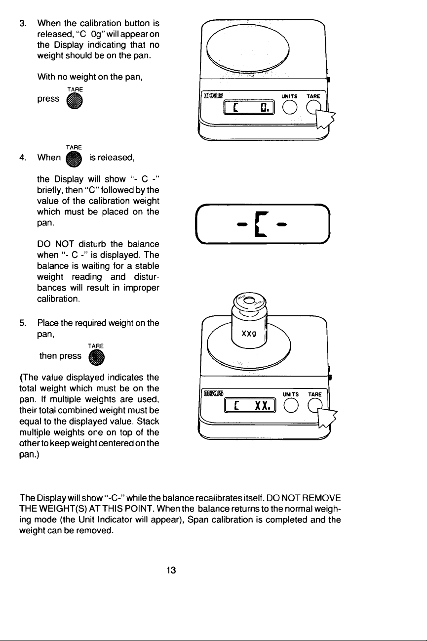
Page 3
Page 4
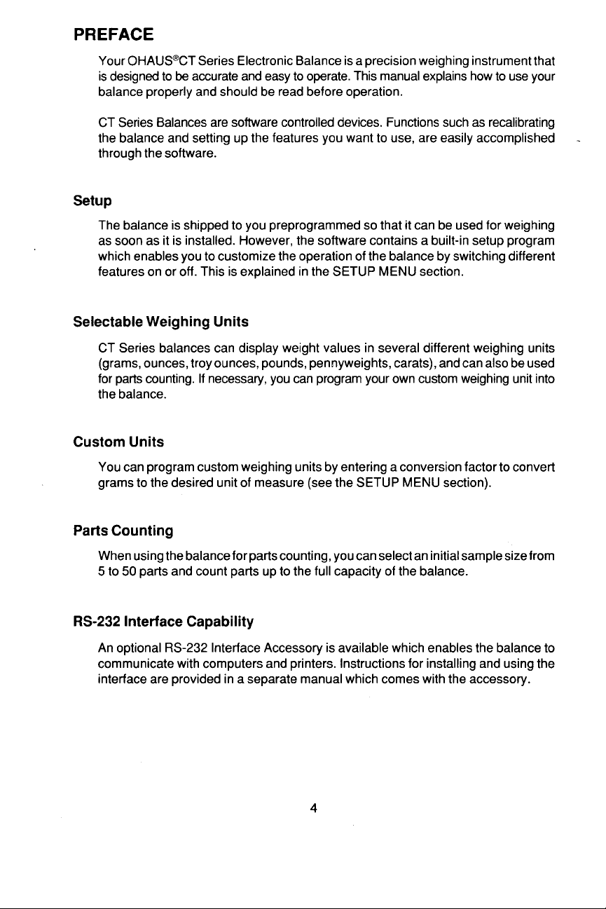
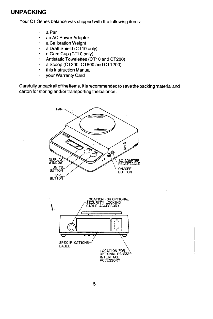
Page 5
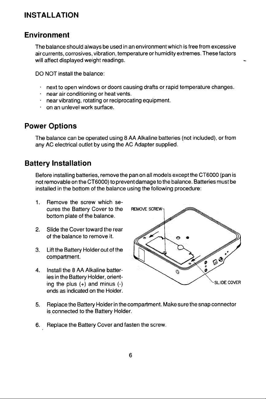
Page 6
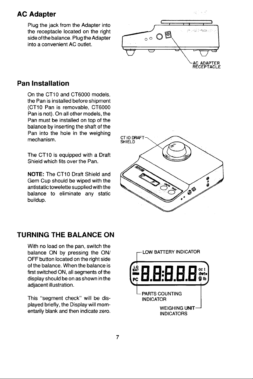
Page 7
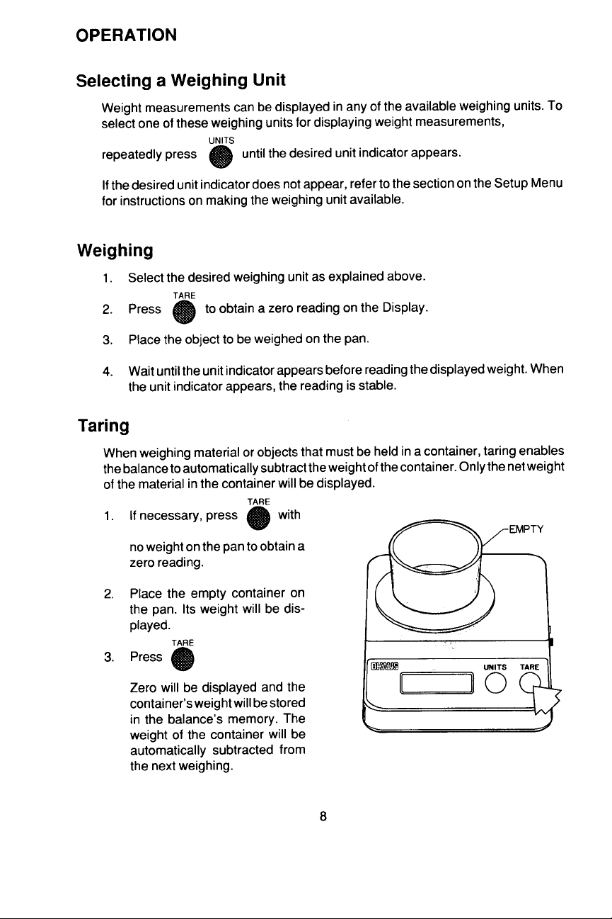
Page 8
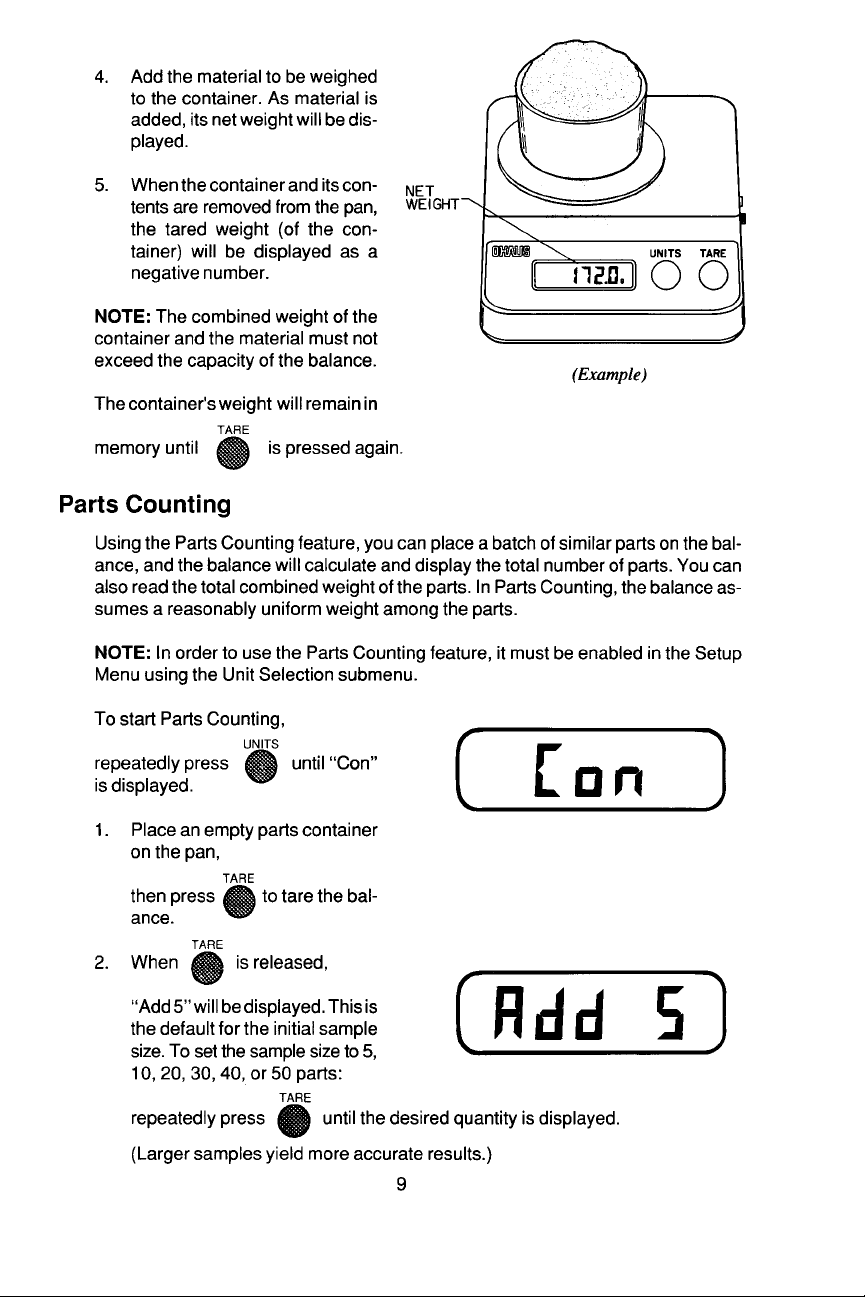
Page 9
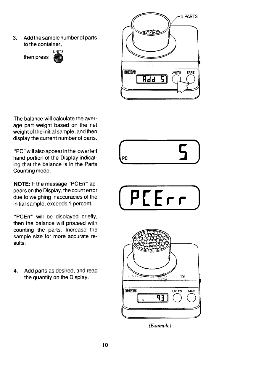
Page 10
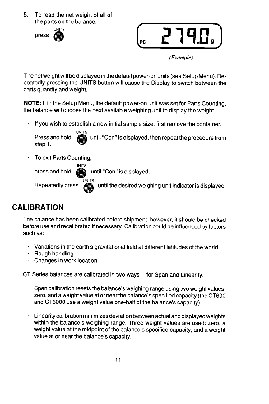
Page 11
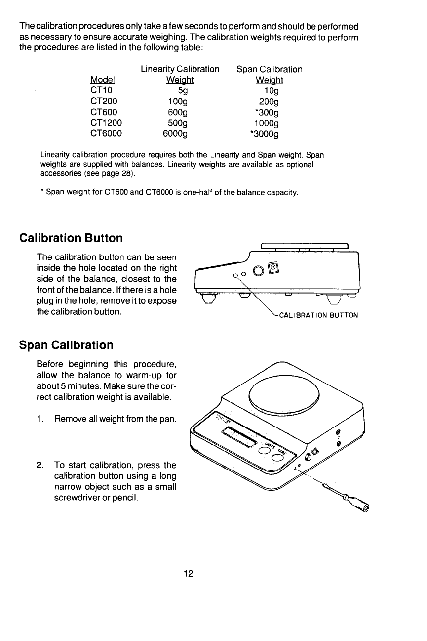
Page 12
Page 13
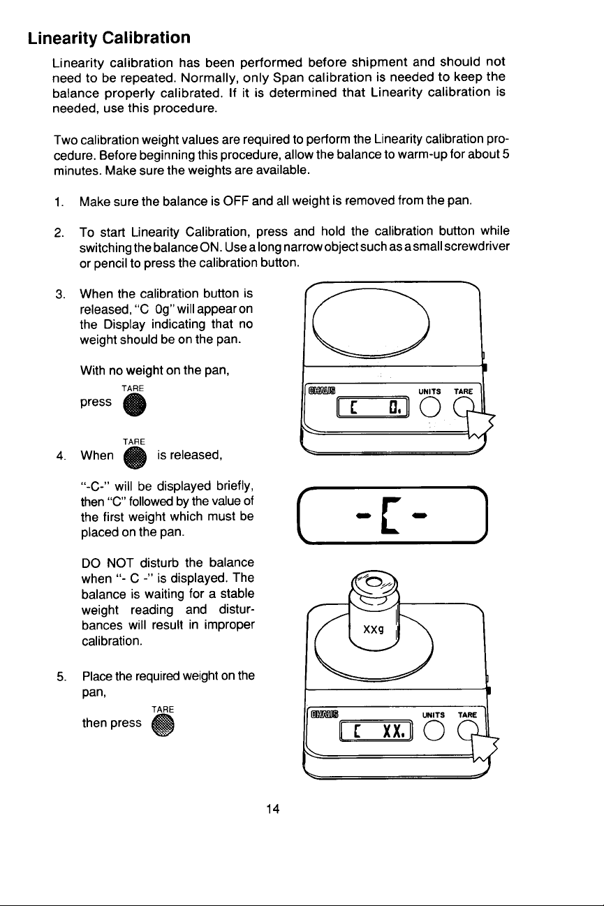
Page 14
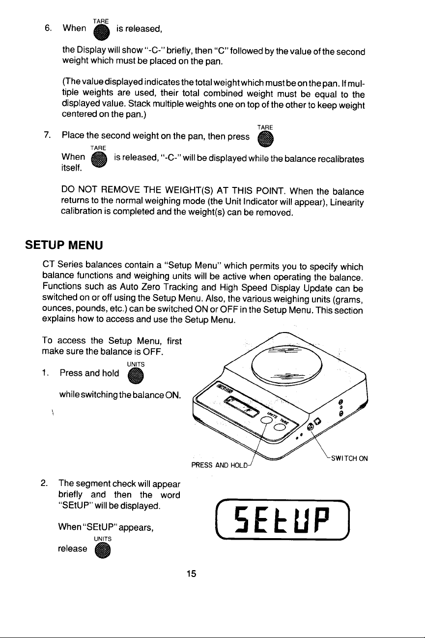
Page 15
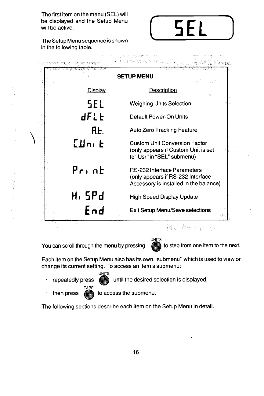
Page 16
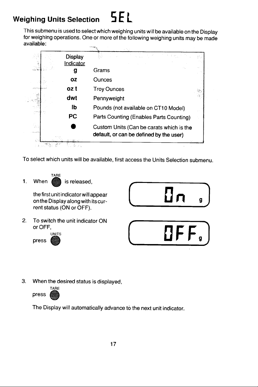
Page 17
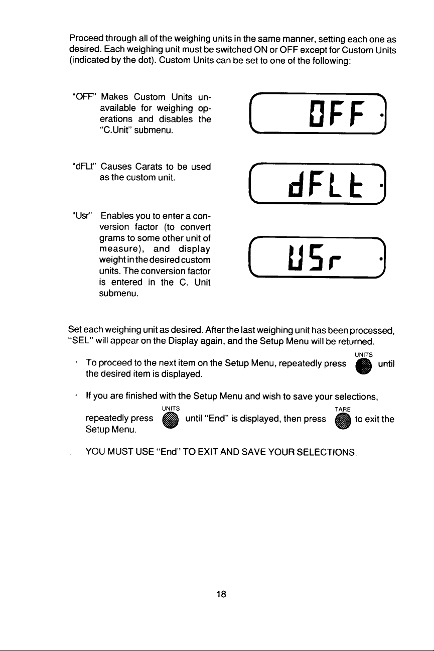
Page 18
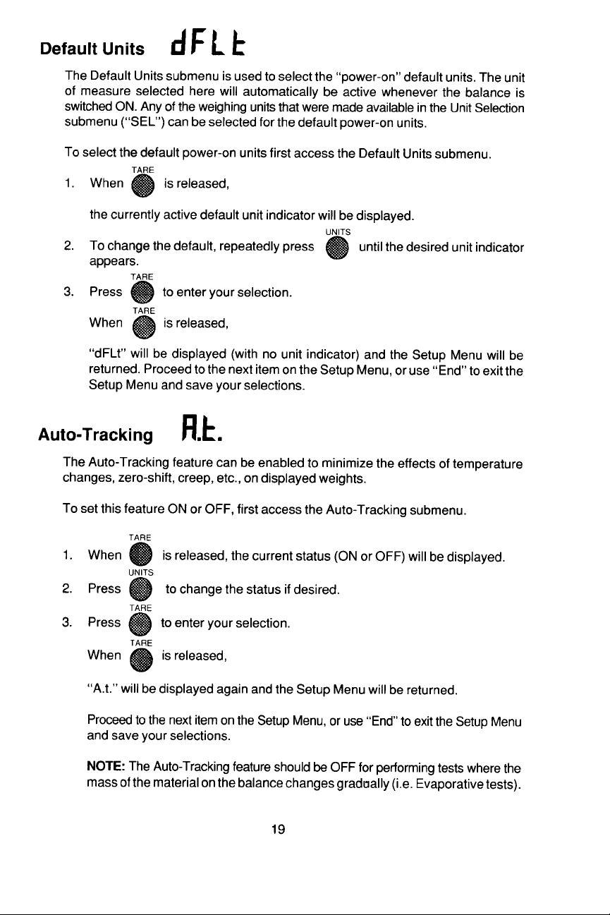
Page 19
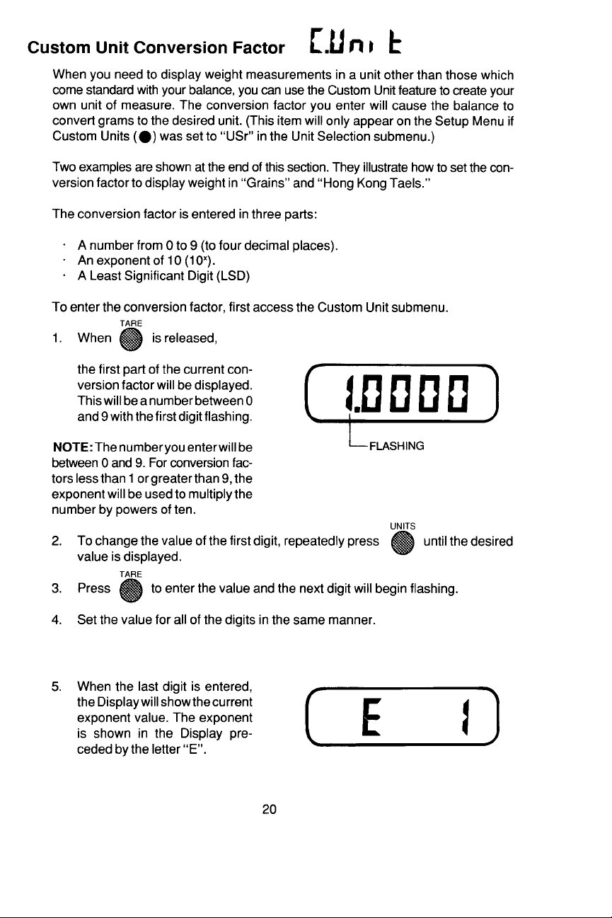
Page 20
Page 21
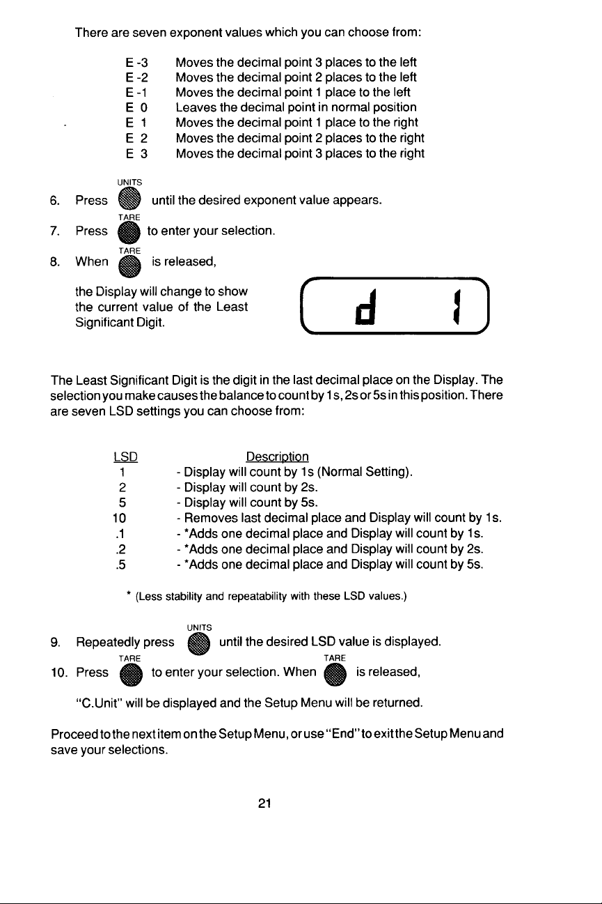
Page 22
Page 23
Page 24
Page 25
Page 26
Page 27
Page 28
Page 29
Page 30

Page 31

Page 32

CT SERIESCT SERIES
CT SERIES
CT SERIESCT SERIES
RS-232 INTERFRS-232 INTERF
RS-232 INTERF
RS-232 INTERFRS-232 INTERF
KITKIT
KIT
KITKIT
AA
A
AA
CECE
CE
CECE
For use with Models
CT10, CT200, CT600, CT600L
CT1200, CT3000L and CT6000
Instruction ManualInstruction Manual
Instruction Manual
Instruction ManualInstruction Manual
WARNING:WARNING:
WARNING: THIS EQUIPMENT GENERATES, USES, AND CAN RADIATE RADIO
WARNING:WARNING:
FREQUENCY ENERGY AND IF NOT INSTALLED AND USED IN ACCORDANCE
WITH THE INSTRUCTION MANUAL, MAY CAUSE INTERFERENCE TO RADIO
COMMUNICATIONS. IT HAS BEEN TESTED AND FOUND TO COMPLY WITH CLASS
“A” REQUIREMENTS IN BOTH PART 15 OF FCC RULES AND THE RADIO INTERFERENCE REGULATION OF THE CANADIAN DOC. THIS EQUIPMENT DOES NOT
EXCEED THE LIMITS FOR RADIO NOISE EMISSIONS. OPERATION OF THIS
EQUIPMENT IN A RESIDENTIAL AREA MAY CAUSE UNACCEPTABLE INTERFERENCE TO RADIO AND TV RECEPTION REQUIRING THE OPERATOR TO TAKE
WHATEVER STEPS ARE NECESSARY TO CORRECT THE INTERFERENCE.
LE PRÉSENT APPAREIL NUMÉRIQUE N’EMET PAS DE BRUITS RADIOÉLECTRIQUES DEPASSANT LES LIMITES APPLICABLES AUX APPAREILS NUMÉRIQUES
DE CLASSE A PRESCRITES DANS LE REGLEMENT SUR LE BROUILLAGE RADIOÉLECTRIQUE EDICTÉ PAR LE MINISTERE DES COMMUNICATIONS DU CANADA.
©©
©
©©
Ohaus Corporation 1989, all rights reservedOhaus Corporation 1989, all rights reserved
Ohaus Corporation 1989, all rights reserved
Ohaus Corporation 1989, all rights reservedOhaus Corporation 1989, all rights reserved
Page 33

The CT Series RS-232 Accessory is a bidirectional interface which enables the balance
to communicate with a printer or computer that is equipped with an RS-232 serial port.
The Interface assembly is easily installed in the balance and all communication
parameters are configured using the Setup Menu (reference the CT Series Manual).
Before installing the Interface assembly, observe the following:
WARNINGWARNING
WARNING
WARNINGWARNING
To prevent damage to the balance, be certain that the power supply is
disconnected before removing the cover.
Even though the balance may have been switched OFF, voltage is present
inside the balance as long as the power supply is connected.
If the AC Adapter is being used, disconnect it.
If batteries are installed, remove them.
INSTALLATIONINSTALLATION
INSTALLATION
INSTALLATIONINSTALLATION
To install the RS-232 Interface Accessory, first remove the Pan from the balance, and turn the balance upside down.
(Do not remove Pan on CT3000L and
CT6000 Models.)
1. The bottom plate is held by four
screws, one located in each corner.
Remove the four screws and lift off
the bottom plate.
NOTE:NOTE:
NOTE: On earlier models the bot-
NOTE:NOTE:
tom plate is held by one screw located toward the center of the plate.
2. On the rear of the balance, a protec-
tive label is provided which covers
the hole for the 9-pin RS-232 connector.
Peel off the label to expose the hole.
3. Place the circuit board and connec-
2
Page 34

tor assembly in the balance so that
the 9-pin connector fits through the
hole.
4. Fasten the assembly using the two
screws provided.
5. Slide the ribbon connector onto the
edge of the main circuit board as
shown in the diagram.
Replace the bottom plate and install
the batteries or AC Adapter. Replace the pan if it was removed.
9-PIN CONNECTOR9-PIN CONNECTOR
9-PIN CONNECTOR
9-PIN CONNECTOR9-PIN CONNECTOR
The balance can now be interfaced with
other equipment utilizing the 9-pin connector which has been installed. The
diagram shows the pin-out and pin de-
scriptions for the connector.
The balance will not output any informa-
tion unless pin 5 (CTS) is held in an ON
state (+3 to +15 VDC). Interfaces not
utilizing the CTS handshake may tie pin
5 to pin 6 to defeat it.
NOTE:NOTE:
NOTE: This interface does not strictly
NOTE:NOTE:
adhere to the official RS-232 standard
(particularly in the connector used). However, it is compatible with what is commonplace in the microcomputer industry.
3
Page 35

SETUPSETUP
SETUP
SETUPSETUP
Once installation is completed, the interface parameters must be entered using the
Setup Menu (reference the CT Series Manual). When the interface is installed in the
balance, the Setup Menu will include an additional item, the Print submenu. Using the
Print submenu to enter the interface parameters includes:
• Selecting a Baud Rate
• Selecting a Data Frame Format (data bits, parity, stop bits)
• Selecting the Auto Print Interval (1-99 seconds)
• Enabling or Disabling the “Print Stable Data Only” feature
To begin, access the Setup Menu as explained in the CT Series manual, then repeatedly
press the UNITS button until “Print” is displayed. When “Print” is displayed, press the
TARE button to access the Print submenu selections. (On Legal for Trade models, the
RE-ZERO button replaces the TARE button.)
The first item displayed will be the RS-232 parameter selection. Pressing the UNITS
button repeatedly enables you to scroll through the Print submenu. Pressing the TARE
button lets you access the displayed selection.
r S232 - Used to select baud rate and data frame
A.P.- Used to set Auto Print Interval (1-99 seconds)
Print
Submenu
S tb. - Used to set “Stable Data Only” feature ON or OFF
End- Used to exit Print submenu and return to main
Setup Menu
Use the following procedures to set each of these parameters.
RS-232 ParametersRS-232 Parameters
RS-232 Parameters
RS-232 ParametersRS-232 Parameters
This selection is used to select the desired baud rate and data frame format. There are
five available baud rates (300, 1200, 2400, 4800, 9600), and nine data frame formats
(numbered 0-8) to choose from. Use the following procedure to set these parameters:
1. Access the RS-232 Parameters selection. When the TARE button is
released, the current baud rate setting will be displayed. The baud rate
is preceded by the letter “b”.
2. Press the UNITS button repeatedly
until the desired baud rate is displayed. Then press the TARE button
to select the displayed baud rate.
4
Page 36

3. Once the baud rate is entered, the
Display will change to show the current frame format selection. This will
be the letters “Fr” followed by a number from 0 to 8.
The number corresponds to one of the following data frames:
Fr. 0Fr. 0
Fr. 0 START 7 STOP STOP
Fr. 0Fr. 0
Fr. 1Fr. 1
Fr. 1 START 7 EVEN STOP
Fr. 1Fr. 1
Fr. 2Fr. 2
Fr. 2 START 7 ODD STOP
Fr. 2Fr. 2
Fr. 3Fr. 3
Fr. 3 START 7 EVEN STOP STOP
Fr. 3Fr. 3
Fr. 4Fr. 4
Fr. 4 START 7 ODD STOP STOP
Fr. 4Fr. 4
BIT DATA BITS BIT BIT
BIT DATA BITS PARITY BIT BIT
BIT DATA BITS PARITY BIT BIT
BIT DATA BITS PARITY BIT BIT BIT
BIT DATA BITS PARITY BIT BIT BIT
Fr. 5Fr. 5
Fr. 5 START 8 STOP
Fr. 5Fr. 5
Fr. 6Fr. 6
Fr. 6 START 8 ODD STOP
Fr. 6Fr. 6
Fr. 7Fr. 7
Fr. 7 START 8 EVEN STOP
Fr. 7Fr. 7
Fr. 8Fr. 8
Fr. 8 START 8 STOP STOP
Fr. 8Fr. 8
BIT DATA BITS BIT
BIT DATA BITS PARITY BIT BIT
BIT DATA BITS PARITY BIT BIT
BIT DATA BITS BIT BIT
Press the UNITS button repeatedly until the desired frame number is displayed.
Then press the TARE button to select the displayed frame number.
When the TARE button is released, “rS232” will be displayed and the Print submenu
is returned.
5
Page 37

Auto Print IntervalAuto Print Interval
Auto Print Interval
Auto Print IntervalAuto Print Interval
The Auto Print feature enables the scale to automatically send displayed data to a printer
or computer, at a specified time interval. The interval can be set from 1 to 99 seconds.
Setting the interval to 0 disables the Auto Print feature. Use the following procedure to
set the Auto Print interval:
1. Access the Auto Print selection. When the TARE button is released, the current
Auto Print interval will be displayed. The number is preceded by the letters “A.P.”
2. Press the UNITS button repeatedly to increase the setting. Holding the UNITS
button down will cause the value to increase more rapidly.
3. Press the TARE button to select the displayed value.
When the TARE button is released, “A.P.” will be displayed and the Print submenu
will be returned.
Print Stable Data OnlyPrint Stable Data Only
Print Stable Data Only
Print Stable Data OnlyPrint Stable Data Only
When enabled, this feature restricts the balance to sending only stable display data
when requested. (Display data is stable when the Unit Indicator is shown in the Display.)
To turn this feature ON or OFF:
1. Access the Stable Data selection. When the TARE button is released, the current
status will be displayed.
2. Press the UNITS button to switch the status ON or OFF as desired.
3. Press the TARE button to select the displayed status.
When the TARE button is released, “Stb.” will be displayed and the Print submenu
will be returned.
NOTE:NOTE:
NOTE: On Legal for Trade models, “Stb.” does not appear. The feature is always ON.
NOTE:NOTE:
Exit Print SubmenuExit Print Submenu
Exit Print Submenu
Exit Print SubmenuExit Print Submenu
When you are finished making your selections, “End” must be used to exit the Print
submenu. Use the following procedure:
1. Access the “End” selection. When the TARE button is released, “Print” will be
displayed and the Setup Menu will be returned.
2. Press the UNITS button repeatedly until End is displayed on the Setup Menu.
3. Press the TARE button to exit the Setup Menu and save your selections.
6
Page 38

DIRECT CONNECTION TO A PRINTERDIRECT CONNECTION TO A PRINTER
DIRECT CONNECTION TO A PRINTER
DIRECT CONNECTION TO A PRINTERDIRECT CONNECTION TO A PRINTER
The balance can be connected directly to a printer using the RS-232 Interface. Display
data can be sent to the printer in the format shown below, using one of three methods:
• using the Auto Print feature
• using the UNITS button (balances with version 2.0 software or later)
• using an external print switch
To send data to the printer using the UNITS button, press and hold the button for at least
three seconds. The word “Print” will be displayed and the current display data will be
sent. If only one weighing unit is enabled (in the Setup Menu), the UNITS button
becomes a dedicated PRINT button and does not have to be held for three seconds.
An external print switch may be connected between pins 9 (PRINT) and 7 (GND) of the
9-pin connector. This must be a normally open switch. When the switch is closed, the
current display data will be sent.
1234567891011121314
±XXX. XXSpXXXStb. Cr Lf
POLARITY
Field is Blank if
positive.
CONNECTION TO A COMPUTERCONNECTION TO A COMPUTER
CONNECTION TO A COMPUTER
CONNECTION TO A COMPUTERCONNECTION TO A COMPUTER
The balance can be connected to a computer using the RS-232 Interface. This
configuration enables full control of balance functions from the computer, except for
switching the scale ON and OFF. The balance will respond to commands sent as ASCII
characters followed by a Carriage Return (CR) or Carriage Return Line Feed (CRLF)
character. The following table defines the accepted commands. Any other control
characters or commands will be ignored.
COMMAND SENT
BY COMPUTER DESCRIPTION BALANCE RESPONSE
P Print Display Data The balance responds by sending the
DISPLAYED VALUE
Number is right justified
padded with zeroes.
displayed data in the format illustrated in
“DIRECT CONNECTION TO PRINTER”.
This includes Polarity, Displayed Value,
Weighing Units, Stability Status followed by
a CRLF.
UNITS
G
OZ
OZT
DWT
LBS
PCS
USR
CT
STABILITY
Blank if stable.
? if unstable.
COMMAND SENT
7
Page 39

BY COMPUTER DESCRIPTION BALANCE RESPONSE
? Print Display Units The balance responds by sending the
current unit indicator and stability status in
the following format:
(Field)
(# of Chars.)
Units Stability CR
3 1 1
M UNITS Button This command has the same effect as
pressing the UNITS button on the front
panel. No data is output.
T TARE Button This command has the same effect as
pressing the TARE button on the front
panel. No data is output.
E Extended UNITS This command has the same effect as
Button pressing and holding the UNITS button on
the front panel.
* L Start Linearity Starts Linearity Calibration procedure (see
Linearity Calibration in CT Series Manual).
* C Start Calibration Starts Span Calibration procedure (see
Span Calibration in CT Series Manual).
0D Turn OFF 1 Second Disables the 1 second delay the balance
Delay waits before responding to a “P” command.
When disabled, the balance responds
immediately.
1D Turn ON 1 Second Enables a 1 second delay in the balance’s
Delay response to a “P” command. This is
provided for computers requiring such a
delay.
* 0S Turn OFF Disables the Stable Data Only printing
"Stable Data Only" feature. When disabled, the balance will
send display data in response to a “P”
command, regardless of the stability status.
* 1S Turn ON Enables the Stable Data Only printing
"Stable Data Only" feature. When the feature is enabled, the
balance will only send stable display data in
response to the “P” command.
* Does not apply to Legal For Trade models.
COMMAND SENT
8
Page 40

BY COMPUTER DESCRIPTION BALANCE RESPONSE
nnA Set Auto Print Set the Auto Print Interval to “nn” seconds
Interval (nn = 0 to 99). Setting the interval to 00
disables the Auto Print function.
* 0Z Turn OFF Auto Zero Disables the Auto Zero Tracking feature
Tracking (see Setup Menu in CT Series Manual).
* 1Z Turn ON Auto Zero Enables the Auto Zero Tracking feature
Tracking (see Setup Menu in CT Series Manual).
** V Print PROM Causes the balance to respond with the
Revision Level revision level of the PROM installed in the
balance. Output is in the format: “CT V_._”.
** N Disable Automatic Permits you to disable the automatic printing
Error Message of error messages output by the balance.
Printing This command is reset on power-off.
** <esc>D Revert to Factory Sets all balance menu selections to the
Default Settings following factory defaults:
All available units enabled
Default units = Grams
* Auto-Zero Tracking is ON
High Speed Display Update is OFF
* Custom Unit = Carats
* Custom Unit Conversion Factor is set to:
1.0000, LSD = 1, Exponent = 0
“Stable Data Only” printing is ON
Auto Print feature is OFF
* Does not apply to Legal For Trade models.
** Available only on balances with version 2.0 software or later.
RS-232 Error MessagesRS-232 Error Messages
RS-232 Error Messages
RS-232 Error MessagesRS-232 Error Messages
If the balance is in an error condition when a request for output occurs, the current error
message number (Err0 - Err6) will be sent in the following format:
(Field)
(# of Chars.)
Error # CR LF
5 1 1
9
Page 41

OPTIONAL ACCESSORIESOPTIONAL ACCESSORIES
OPTIONAL ACCESSORIES
OPTIONAL ACCESSORIESOPTIONAL ACCESSORIES
Ohaus
Part Number
Interface Cables:
Blunt End (User Defined) 90641-01
IBM® - PC 90641-02
Apple® IIe 90641-03
Epson HX-20 90641-04
Apple® IIc 90641-05
®
Apple is a registered trademark of Apple Corporation.
®
IBM is a registered trademark of International Business Machines Corporation.
OHAUS® is the registered trademark of Ohaus Corporation as are the following
trademarks: AUTOGRAM® , BRAINWEIGH® , CENT-O-GRAM® , CHECK-O-GRAM® ,
CUBE-O-GRAM® , DEC-O-GRAM® , DIAL-O-GRAIN® , DIAL-O-GRAM® , DU-OMEASURE® , GALAXY® , LUME-O-GRAM® , PORT-O-COUNT® , PORT-O-GRAM® ,
PRACT-O-GRAM® , PRIMER® , STO-A-WEIGH® , TOUCH-N-WEIGH® , 5-0-5® , and 1010® .
OHAUS CORP.OHAUS CORP.
OHAUS CORP.
OHAUS CORP.OHAUS CORP.
29 Hanover Road Broad Lane, Cottenham
Florham Park, N.J. 07932 Cambridge CB4 4SW
Tel: 201-377-9000 ENGLAND
Telex: 6853191 OHAUS UW Tel: 0954-51343
Fax: 201-593-0359 Telex: 817285 OSCALE G
OHAUS EUROPE, LTD.OHAUS EUROPE, LTD.
OHAUS EUROPE, LTD.
OHAUS EUROPE, LTD.OHAUS EUROPE, LTD.
Fax: 0954-50205
P/N 77171-00 R1289
Page 42

Ohaus CorporationOhaus Corporation
Ohaus Corporation
Ohaus CorporationOhaus Corporation
29 Hanover Road
Florham Park NJ
07932-0900
PORTABLE
Advanced
Electronic Balances
CT Series
Instruction Manual
Page 43

NOTICE:NOTICE:
NOTICE: THIS EQUIPMENT HAS BEEN TESTED AND FOUND TO COMPLY
NOTICE:NOTICE:
WITH THE LIMITS FOR A CLASS A DIGITAL DEVICE, PURSUANT TO PART 15
OF THE FCC RULES.
THESE LIMITS ARE DESIGNED TO PROVIDE REASONABLE PROTECTION
AGAINST HARMFUL INTERFERENCE WHEN THE EQUIPMENT IS OPERATED
IN A COMMERCIAL ENVIRONMENT. THIS EQUIPMENT GENERATES, USES,
AND CAN RADIATE RADIO FREQUENCY ENERGY AND, IF NOT INSTALLED
AND USED IN ACCORDANCE WITH THE INSTRUCTION MANUAL, MAY CAUSE
HARMFUL INTERFERENCE TO RADIO COMMUNICATIONS. OPERATION OF
THIS EQUIPMENT IN A RESIDENTIAL AREA IS LIKELY TO CAUSE HARMFUL
INTERFERENCE IN WHICH CASE THE USER WILL BE REQUIRED TO CORRECT THE INTERFERENCE AT HIS OWN EXPENSE.
THIS DIGITAL APPARATUS DOES NOT EXCEED THE CLASS A LIMITS FOR
RADIO NOISE EMISSIONS FROM DIGITAL APPARATUS AS SET OUT IN THE
INTERFERENCE-CAUSING EQUIPMENT STANDARD ENTITLED “DIGITAL APPARATUS”, ICES-003 OF THE DEPARTMENT OF COMMUNICATIONS.
CET APPAREIL NUMERIQUE RESPECTE LES LIMITES DE BRUITS
RADIOELECTRIQUES APPLICABLES AUX APPAREILS NUMERIQUES DE CLASSE
A PRESCRITES DANS LA NORME SUR LE MATERIEL BROUILLEUR : “APPAREILS
NUMERIQUES”, NMB-003 EDICTEE PAR LE MINISTRE DES COMMUNICATIONS.
Unauthorized changes or modifications to this equipment are not permitted.
2
Page 44

TABLE OF CONTENTSTABLE OF CONTENTS
TABLE OF CONTENTS
TABLE OF CONTENTSTABLE OF CONTENTS
INTRODUCTION.................................................................................................. 5
DESCRIPTION..................................................................................................... 5
FEATURES .......................................................................................................... 6
UNPACKING ........................................................................................................ 7
INSTALLATION.................................................................................................... 7
Environment .................................................................................................. 7
Power Options .............................................................................................. 8
Battery Installation ........................................................................................ 8
AC Adapter ................................................................................................... 8
Model CT200 Shipping Bracket .................................................................... 9
Platform Installation ...................................................................................... 9
Weigh Below Hook...................................................................................... 10
OPERATION ...................................................................................................... 10
Turning the Balance On and Off................................................................. 10
Checking Calibration ................................................................................... 11
Weighing ..................................................................................................... 1 1
Taring .......................................................................................................... 12
Parts Counting ............................................................................................ 13
Printing ........................................................................................................ 14
USING MENUS TO CONFIGURE THE BALANCE........................................... 15
CALIBRATION MENU ........................................................................................ 16
Calibration Menu Protection ....................................................................... 16
Calibration Masses ..................................................................................... 16
Span Calibration ......................................................................................... 17
Linearity Calibration .................................................................................... 1 8
End .............................................................................................................. 18
SETUP MENU.................................................................................................... 20
Accessing the Setup Menu ......................................................................... 21
Reset to Factory Settings ........................................................................... 21
Unit Selection .............................................................................................. 2 2
Taels ........................................................................................................... 22
Custom Units .............................................................................................. 23
3
Page 45

Custom Units Conversion Factor ................................................................ 24
Example ................................................................................................... 26
Averaging Level .......................................................................................... 27
Stability Range ............................................................................................ 28
Auto-Zero .................................................................................................... 29
Parts Counting Error Level ......................................................................... 30
Auto-Off ....................................................................................................... 31
End .............................................................................................................. 31
CALIBRATION LOCK-OUT PROTECTION ....................................................... 32
CARE AND MAINTENANCE ............................................................................. 33
TROUBLESHOOTING ....................................................................................... 33
Error Codes ................................................................................................. 34
SERVICE INFORMATION ................................................................................. 34
PARTS INFORMATION ..................................................................................... 35
REPLACEMENT PARTS ................................................................................... 35
SECURITY ......................................................................................................... 36
ACCESSORIES ................................................................................................. 36
SPECIFICATIONS ............................................................................................. 37
LIMITED WARRANTY ....................................................................................... 38
4
Page 46

INTRODUCTIONINTRODUCTION
INTRODUCTION
INTRODUCTIONINTRODUCTION
This manual covers installation, operation and troubleshooting for the OHAUS
Portable
CT6000. To ensure proper operation of the balance, please read this manual
completely.
DESCRIPTIONDESCRIPTION
DESCRIPTION
DESCRIPTIONDESCRIPTION
Advanced
Electronic Balances, Models CT10, CT200, CT600, CT1200 and
®
The Ohaus Portable
signed to provide years of service with virtually no maintenance. The Portable
Advanced
one piece solid-state precision electronics PC board, and a five digit LCD display which
is 0.5 inches in height. All Portable
measure in grams and can be set to measure in other units of measure as desired.
Each balance operates through a series of menus which enable precise calibration and
the selection of various parameters which enhance operation. A built in lock switch
prevents calibration settings from being changed. Power is supplied through an AC
adapter or batteries. Accessories include: an RS232 Interface Kit which allows printing
of results through an external computer or printer, security device, calibration masses,
scoops and carrying cases. See accessory section.
housing is constructed of a material which is impact resistant, contains a
Advanced
balances are precision weighing instruments, de-
Advanced
balances are initially factory set to
Portable
Advanced
5
Balance
Page 47

FEATURES
Portable
and configure the balance for specific operating requirements. When an optional
RS232 Interface is installed, a third menu is available.
•
•
•
When the balance is first turned on, it can be used to weigh in grams or tare items
without setting the menus. Refer to the individual menus in this manual for detailed
descriptions and procedures for programming.
Advanced
CALIBRATIONCALIBRATION
CALIBRATION Menu - Allows the balance to be calibrated by using either Span or
CALIBRATIONCALIBRATION
Linearity calibration methods.
SETUPSETUP
SETUP Menu - Allows the balance to be set for environmental conditions and
SETUPSETUP
customized for specific weighing functions.
PRINTPRINT
PRINT Menu - When an
PRINTPRINT
of parameters under which the balance will interface with a computer or a printer.
Instructions for installing and using the interface are provided in a separate manual
which comes with the accessory.
balances contain two display menus which enable you to calibrate
optional
RS232 Interface is installed, allows the selection
6
Page 48

UNPACKINGUNPACKING
UNPACKING
UNPACKINGUNPACKING
All Portable
adapter, instruction manual and warranty card. Items checked below are supplied with
specific models as follows:
Calibration MassCalibration Mass
Calibration Mass
Calibration MassCalibration Mass
Draft ShieldDraft Shield
Draft Shield
Draft ShieldDraft Shield
Gem CupGem Cup
Gem Cup
Gem CupGem Cup
Weigh Below HookWeigh Below Hook
Weigh Below Hook
Weigh Below HookWeigh Below Hook
Antistatic TowelettesAntistatic Towelettes
Antistatic Towelettes
Antistatic TowelettesAntistatic Towelettes
ScoopScoop
Scoop
ScoopScoop
Hex KeyHex Key
Hex Key
Hex KeyHex Key
Carefully unpack all items. The platform for models CT200, CT600 and CT1200 is
packed in the upper portion of the packing material. Be sure to remove the platform
and do not discard the packing material. It is recommended to save the packing
material and carton for storing and/or transporting the balance. The packing material
may also be used as an insert for the Vinyl carrying case (optional accessory) listed
in the accessory section of this manual.
Advanced
balances are supplied with a weighing platform, AC power
CT10CT10
CT10
CT10CT10
✓ ✓
✓
✓ ✓
✓ ✓
✓
✓ ✓
✓ ✓
✓
✓ ✓
✓ ✓
✓
✓ ✓
CT200CT200
CT200
CT200CT200
✓ ✓
✓
✓ ✓
✓ ✓
✓
✓ ✓
✓ ✓
✓
✓ ✓
✓✓
✓
✓✓
✓✓
✓
✓✓
CT600CT600
CT600
CT600CT600
✓ ✓
✓
✓ ✓
✓ ✓
✓
✓ ✓
✓ ✓
✓
✓ ✓
CT1200CT1200
CT1200
CT1200CT1200
✓ ✓
✓
✓ ✓
✓ ✓
✓
✓ ✓
Location for optional
security device
CT6000CT6000
CT6000
CT6000CT6000
Display
Window
INSTALLATIONINSTALLATION
INSTALLATION
INSTALLATIONINSTALLATION
EnvironmentEnvironment
Environment
EnvironmentEnvironment
Balance performance can be affected by excessive air currents, corrosives, vibration,
temperature or humidity extremes.
DO NOTDO NOT
DO NOT use the balance:
DO NOTDO NOT
• Next to open windows or doors causing drafts or rapid temperature changes.
• Near air conditioning or heat vents.
• Near vibrating, rotating or reciprocating equipment.
• On an non-level work surface.
• Near corrosive vapors (example: nitric acid).
AC Adapter
Receptacle
Calibration Menu
Lockout Switch
Specifications Label
7
Location for optional
RS232 interface
Page 49

Power OptionsPower Options
Power Options
Power OptionsPower Options
The balance can be operated using 8 AA alkaline batteries (not included), or from any
AC electrical outlet by using the AC adapter supplied.
Battery InstallationBattery Installation
Battery Installation
Battery InstallationBattery Installation
1. Remove the platform on all models except the CT6000 (platform is not removable
on the CT6000).
2. Turn the balance over.
3. Press the tabs on the battery cover inward and lift the cover off.
4. Remove the battery holder.
5. Install the 8 AA alkaline batteries in the battery holder, orienting the plus (+) and
minus (-) ends as indicated on the holder.
6. Replace the battery holder in the compartment. Make sure the snap connector is
connected.
7. Replace the battery cover.
NOTENOTE
NOTE: The illustration shows a balance
NOTENOTE
with four feet. Certain models contain
only three feet.
AC AdapterAC Adapter
AC Adapter
AC AdapterAC Adapter
Plug the jack from the adapter into the
receptacle located on the right side of the
balance. Plug the adapter into a convenient AC outlet.
Press tabs to
remove cover
8
Page 50

Model CT200 Shipping BracketModel CT200 Shipping Bracket
Model CT200 Shipping Bracket
Model CT200 Shipping BracketModel CT200 Shipping Bracket
The Model CT200 is factory packed
with a shipping bracket which must be
removed before installing the Platform.
1. Using the hex key provided, remove the screw which secures
the bracket to the transducer.
2. Slide the bracket out to remove it.
Platform InstallationPlatform Installation
Platform Installation
Platform InstallationPlatform Installation
On the CT10 and CT6000 models, the
platform is installed before shipment
(CT10 platform is removable, CT6000
platform is not). On all other models,
the platform must be installed on top of
the balance by inserting the shaft of the
platform into the hole in the weighing
mechanism.
CAUTION:CAUTION:
CAUTION: DO NOT ATTEMPT TO
CAUTION:CAUTION:
REMOVE THE DOWN STOP
ADJUSTMENT SCREW.
BRACKET
REMOVE SMALLER SCREW
(TURN COUNTERCLOCKWISE)
The CT10 is equipped with a draft
shield which fits over the platform.
NOTE:NOTE:
NOTE: The CT10 draft shield and gem
NOTE:NOTE:
cup should be wiped with the antistatic
towelette supplied with the balance to
eliminate any static buildup.
9
Page 51

Weigh Below HookWeigh Below Hook
Weigh Below Hook
Weigh Below HookWeigh Below Hook
A weigh below hook is provided with models CT200, CT600 and CT1200 for below
balance weighing applications.
To install the hook, turn the balance over
holding the platform in place. Screw the
hook into the platform shaft from the bottom of the balance. Tighten finger-tight.
Mount the balance on a suitable surface or
stand which permits below balance weighing.
OPERATIONOPERATION
OPERATION
OPERATIONOPERATION
Weigh Below Hook
Turning the Balance On and OffTurning the Balance On and Off
Turning the Balance On and Off
Turning the Balance On and OffTurning the Balance On and Off
With no load on the platform, press .
All segments of the display will turn on,
then the software version is displayed.
The display will momentarily blank and
then indicate zero.
NOTE: NOTE:
NOTE: Allow at least 5 minutes for the
NOTE: NOTE:
balance to temperature stabilize before
using. If the balance is moved to a different temperature environment, allow additional time to stabilize.
To turn the balance off, press and
hold until OFF is displayed, then
release it.
Low Battery Indicator
Parts Counting Indicator
Weighing Unit Indicators
&
Stability Indicators
10
Page 52

Checking CalibrationChecking Calibration
Checking Calibration
Checking CalibrationChecking Calibration
Before using the balance, its calibration
should be checked. The balance has
been calibrated before shipment, however, calibration is influenced by factors
such as:
• Variations in the earths gravitational
field at different latitudes of the world.
• Rough handling.
• Changes in work location.
• Height above sea level.
To check the balance’s calibration, place
a known mass on the center of the platform and read the displayed weight.
If the displayed weight differs from the
known mass by more than acceptable
limits, refer to the Calibration Menu and
the Specifications at the rear of the manual.
WeighingWeighing
Weighing
WeighingWeighing
1. Press to set the display to zero.
2. Place the object to be weighed on the
platform.
3. Wait until the unit indicator appears
before reading the displayed weight.
When the unit indicator appears, the
reading is stable.
11
Page 53

TaringTaring
Taring
TaringTaring
When weighing samples that must be held
in a container, taring enables the balance
to subtract the weight of the container and
display only the net weight of the sample.
1. Press
form to set the display to zero.
2. Place the empty container on the platform. Its weight will be displayed.
3. Press . Zero will be displayed
and the container’s weight will be stored
in the balance’s memory.
4. Add the sample to the container and
read its net weight on the display.
NOTE:NOTE:
NOTE: The combined weight of the con-
NOTE:NOTE:
tainer and the sample
capacity of the balance.
5. When the container and its con-
with no load on the plat-
must notmust not
must not exceed the
must notmust not
tents are removed, the container
weight will be displayed as a
negative number.
The tared weight will remain in
memory until is pressed
again or the balance is turned
off.
(Example)
12
Page 54

Parts CountingParts Counting
Parts Counting
Parts CountingParts Counting
Parts Counting must be enabled in the
Setup menu before using this procedure.
The balance will count parts based on the
weight of a reference sample, 5, 10, 20,
30, 40 or 50 parts. For optimum results,
the parts should be uniform in weight.
until
1. Repeatedly press
PC
CON
is displayed.
2. Place a container on the platform,
then press
plays
ADD 5 which is the preset
PC
. The balance dis-
reference quantity.
3. To change the reference quantity,
repeatedly press until the desired quantity is displayed.
Parts Counting Factory SettingsParts Counting Factory Settings
Parts Counting Factory Settings
Parts Counting Factory SettingsParts Counting Factory Settings
Parts Counting Mode ........... Disabled
PC Err ......................................... OFF
NOTE: NOTE:
NOTE: If you need to exit or restart parts
NOTE: NOTE:
counting at any time, press and hold
until PC CON is displayed, then release it.
Return to step 2 to restart, or press
for other weighing functions.
4. Add the displayed number of parts to
the container, then press
. The
balance will display the current number of parts.
13
Page 55

NOTENOTE
NOTE: If PCErr is displayed, the sample is
NOTENOTE
too small to provide accurate results within
the selected parts counting error level (PC
Err of the Setup menu).
5. Add parts to the container as desired
and read the quantity on the display.
NOTENOTE
NOTE: The reference quantity will remain
NOTENOTE
in memory until it is changed or the balance is turned off.
6. To switch between viewing the quantity and weight of the parts,
press .
PrintingPrinting
Printing
PrintingPrinting
If the optional RS232 interface is installed,
(Example)
display data can be output from the balance. The
different manner depending upon if more
than one measuring unit is selected.
When only one measuring unit is enabled, a short press on
printing when -P- is displayed. A long
press will turn the balance off. When
more than one measuring unit is enabled,
a short press on
suring unit, a one-second press will initate
printing, a long press will turn the balance
off. To print data, press and
hold
quickly release it.
button operates in a
will enable
changes the mea-
until -P- is displayed, then
14
Page 56

USING MENUS TO CONFIGURE THE BALANCEUSING MENUS TO CONFIGURE THE BALANCE
USING MENUS TO CONFIGURE THE BALANCE
USING MENUS TO CONFIGURE THE BALANCEUSING MENUS TO CONFIGURE THE BALANCE
The following illustration identifies the items in each menu and the factory default
settings are shown in bold type.
CAL
SPAN
LINEARITY
END
SETUP
RESET
Yes,No
UNIT SELECTION
gg
g, oz, oz t, dwt, lb,
gg
t, • (custom), PC
DFLT/USR
AVERAGING LEVEL
11
0,
1, 2
11
STABILITY
1d1d
.5d,
1d, 2d, 5d
1d1d
AUTO ZERO
.5d.5d
OFF,
.5d, 1d,
.5d.5d
3d
CUSTOM UNIT
CONVERSION
FACTOR
Mantissa
1.00001.0000
1.0000
1.00001.0000
Exponent
E0E0
E0,E1, E2,E3,
E0E0
E -3,E -2, E-1
LSD
.1d, .2d, .5d,
2d, 5d, 10d
PARTS COUNTING
ERROR LEVEL
OFFOFF
OFF, 1, 2.5, 5
OFFOFF
AUTO OFF
OFFOFF
OFF, 60, 120, 180
OFFOFF
PRINT
NOTE: Refer to instructions
provided with the optional
RS232 interface kit.
1d1d
1d,
1d1d
END
To access a menu, press and hold until desired menu appears, then release it.
Use these buttons to step through menus and select submenus:
next
selection
select
displayed item
15
Page 57

CALIBRATION MENUCALIBRATION MENU
CALIBRATION MENU
CALIBRATION MENUCALIBRATION MENU
Portable
Linearity calibration. Span calibration resets the balance’s weighing range using two
points: zero and a calibrated mass value at or near the balance’s capacity. Linearity
calibration minimizes deviation between actual and displayed weights within the
balance’s weighing range using three points: zero, a calibrated mass value within the
balances weighing range, and a value at or near the balance’s specified capacity. The
illustration below indicates the sequence in which submenus appear on the Calibration
menu.
Calibration Menu ProtectionCalibration Menu Protection
Calibration Menu Protection
Calibration Menu ProtectionCalibration Menu Protection
The Calibration menu may be locked out
to prevent unauthorized access. To lock
out calibration menu, refer to the section
titled Calibration Lock-Out Protection.
Calibration MassesCalibration Masses
Calibration Masses
Calibration MassesCalibration Masses
Before beginning calibration, make sure
calibrated masses are on hand. If you
begin calibration and realize masses are
not available, either turn the balance off, or
go through the procedure without masses.
The balance will use previously stored
calibration data. Calibration should be
performed as necessary to ensure accurate weighing. Masses required to perform the procedures are listed in the adjacent table.
Advanced
balances can be calibrated in two ways: Span calibration or
CAL
SPAN
LINEARITY
END
Required Calibration MassesRequired Calibration Masses
Required Calibration Masses
Required Calibration MassesRequired Calibration Masses
Model Span LinearityModel Span Linearity
Model Span Linearity
Model Span LinearityModel Span Linearity
Masses Masses Masses Masses
Masses Masses
Masses Masses Masses Masses
CT10 10g 5g, 10g
CT200 200g 100g, 200g
CT600 300g (2) 300g
CT1200 1000g 500g, 1000g
CT6000 2000g (3) 2000g
1000g 1000g
16
Page 58

Span CalibrationSpan Calibration
Span Calibration
Span CalibrationSpan Calibration
1. Press and hold until CAL is displayed, then release it. Balance will
display SPAN.
2. Press
will be displayed indicating that no
mass should be on the platform.
3. Press
-C- followed by the value of the mass
which must be placed on the platform.
NOTE: NOTE:
NOTE: Do not disturb the balance when
NOTE: NOTE:
-C- is displayed. Disturbances will result
in improper calibration.
4. Place the required mass on the platform and press . The display will
show -C- while the balance recali-
brates. When the mass on the plat-
. When released, C 0g
. The display will show
form is displayed along with the current unit indicator, the balance is recalibrated.
17
Page 59

Linearity CalibrationLinearity Calibration
Linearity Calibration
Linearity CalibrationLinearity Calibration
1. Press and hold until CAL is
displayed, then release. Balance will
display SPAN.
2. Press
LIN.
3. Press . When released, C 0g
will be displayed, indicating that no
mass should be on the platform.
4. Press
-C- followed by the value of the mass
which must be placed on the platform.
5. Place the required mass on the platform.
and the display will show
. The display will show
18
Page 60

6. Press
-C- momentarily, then C followed by
the next mass to be placed on the
platform. Do not disturb the balance
when -C- is displayed. Disturbances
will result in improper calibration.
7. Place the required mass on the plat-
. The display will show
form, then press
will show -C- while the balance reca-
librates. When the mass on the platform is displayed along with the current unit indicator, the balance is recalibrated.
EndEnd
End
EndEnd
If you have entered the Calibration menu
and do not wish to calibrate the balance,
use END to return to normal weighing
operations.
1. Repeately press
displayed.
2. Press
ance will returned to normal weighing
operations.
. When released, the bal-
. The display
until END is
19
Page 61

SETUP MENUSETUP MENU
SETUP MENU
SETUP MENUSETUP MENU
The Setup menu is used to customize the operation of the balance for your specific
requirements. It contains submenus which enable you to turn features on or off, and
program balance parameters. The illustration below indicates the sequence in which
submenus appear on the Setup menu.
SETUP
RESET
Yes,No
UNIT SELECTION
gg
g, oz, oz t, dwt, lb,
gg
t, • (custom), PC
DFLT/USR
AVERAGING LEVEL
11
0,
1, 2
11
STABILITY
1d1d
.5d,
1d, 2d, 5d
1d1d
AUTO ZERO
.5d.5d
OFF,
.5d, 1d,
.5d.5d
3d
CUSTOM UNIT*
CONVERSION
FACTOR
Mantissa
1.00001.0000
1.0000
1.00001.0000
Exponent
E0E0
E0,E1, E2,E3,
E0E0
E -3,E -2, E-1
LSD
.1d, .2d, .5d,
2d, 5d, 10d
PARTS COUNTING**
ERROR LEVEL
OFFOFF
OFF, 1, 2.5, 5
OFFOFF
AUTO OFF
OFFOFF
OFF, 60, 120, 180
OFFOFF
1d1d
1d,
1d1d
END
* C.UNIT only appears in menu if custom unit is enabled in SEL submenu.
** PC ERR only appears in menu if parts counting is enabled in SEL submenu.
20
Page 62

Accessing the Setup MenuAccessing the Setup Menu
Accessing the Setup Menu
Accessing the Setup MenuAccessing the Setup Menu
To access the Setup menu, press and hold
until SETUP is displayed, then re-
lease.
To access a submenu:
1. Repeatedly press
sired submenu is displayed.
2. Press
submenu.
NOTE:NOTE:
NOTE: You must use END to store any
NOTE:NOTE:
changes you make to the Setup menu.
The following sections describe each item
on the Setup menu in detail.
Reset to Factory SettingsReset to Factory Settings
Reset to Factory Settings
Reset to Factory SettingsReset to Factory Settings
This submenu enables you to reset all
Setup menu selections to the original factory settings outlined in the adjacent table.
To reset to factory settings:
1. Access the Reset submenu.
2. Press to enter RESET.
3. Press repeatedly to change the
setting from YES to NO. Selecting
YES resets the Setup menu to the
original factory settings.
to select the displayed
until the de-
SETUP MENUSETUP MENU
SETUP MENU
SETUP MENUSETUP MENU
FACTORY SETTINGSFACTORY SETTINGS
FACTORY SETTINGS
FACTORY SETTINGSFACTORY SETTINGS
Unit Selection g
Averaging Level 1
Stability 1d
Auto Zero .5d
Conversion Factor
Mantissa 1.0000
Exponent 0
LSD 1
PC Error Level OFF
Auto Off OFF
4. Press
setting.
to accept the displayed
21
Page 63

Unit SelectionUnit Selection
Unit Selection
Unit SelectionUnit Selection
The Unit Selection submenu permits you
to specify which weighing units and operating modes will be enabled for use during operation. The adjacent table lists the
units and modes available on Portable
Advanced
1. Access the Sel submenu.
2. Press , the display will show
balances.
the grams unit indicator (g) along
with the current status (ON/OFF).
Display Weighing Units and ModesDisplay Weighing Units and Modes
Display Weighing Units and Modes
Display Weighing Units and ModesDisplay Weighing Units and Modes
Indicator Indicator
Indicator
Indicator Indicator
g
oz ounces
ozt troy ounces
dwt pennyweight
lb pounds
t taels
• custom unit
pc parts counting
gramsgrams
grams
gramsgrams
3. Press
4. Press
status, when released, the display
will show the next unit indicator along
with the current status.
5. Set each unit or mode ON or OFF as
in steps 3 and 4.
TaelsTaels
Taels
TaelsTaels
If taels are enabled, you will be required
to choose one of three different taels:
Hong Kong, Singapore, or Taiwan.
1. When the display shows TAEL 1,
press
if desired.
2. Press to accept the displayed
tael.
to change the status.
to accept the displayed
to change to another tael
Hong Kong
Singapore
22
Taiwan
Page 64

Unit Selection (Cont.)Unit Selection (Cont.)
Unit Selection (Cont.)
Unit Selection (Cont.)Unit Selection (Cont.)
Proceed through all of the weighing units
in the same manner, setting each one as
desired.
Custom UnitsCustom Units
Custom Units
Custom UnitsCustom Units
Custom Units can be set to one of the
following:
DFLT Causes carats to be used as the
custom unit.
USR Enables you to enter a conversion
factor (to convert grams to some
other unit of measure), and display
weight in the desired custom units.
The conversion factor is entered in
the C. Unit submenu.
23
Page 65

Custom Unit Conversion FactorCustom Unit Conversion Factor
Custom Unit Conversion Factor
Custom Unit Conversion FactorCustom Unit Conversion Factor
When you need to display weight measurements in a weighing unit other than those
provided standard with the balance, this feature can be used to create your own custom
weighing unit. It permits you to enter a conversion factor which the balance will use to
convert grams to the desired unit of measure.
One example is shown at the end of this section. It illustrates how to set the conversion
factors to display weight in Grains.
Conversion Weight Weight
Factor x in = in
grams custom unit
Conversion factors are expressed in scientific notation and entered into the balance in three parts:
• A number between 0 and 9 to four
decimal places
• A power of 10 called the exponent.
• A least significant digit (LSD).
Use the following procedure to enter conversion factors:
1. Access the C.Unit submenu.
2. The mantissa of the current conversion factor will be displayed. This will
be a number between 0 and 9.9999
with the first digit flashing. For conversion factors outside of this range,
the exponent will be be used to move
the decimal point.
3. Press
to change the value of
SCIENTIFIC NOTATIONSCIENTIFIC NOTATION
SCIENTIFIC NOTATION
SCIENTIFIC NOTATIONSCIENTIFIC NOTATION
NumberNumber
Number
NumberNumber
BetweenBetween
Between
Conv.Conv.
Conv.
Conv.Conv.
FactorFactor
Factor
FactorFactor
BetweenBetween
0 and0 and
0 and
0 and0 and
9.99999.9999
9.9999
9.99999.9999
PowerPower
Power
PowerPower
of 10of 10
of 10
of 10of 10
Man-Man-
Man-
Man-Mantissatissa
tissa
tissatissa
Exp.Exp.
Exp.
Exp.Exp.
1234 = 1.234 x 1000 = 1.234 x 10
123.4 = 1.234 x 100 = 1.234 x 10
12.34 = 1.234 x 10 = 1.234 x 10
1.234 = 1.234 x 1 = 1.234 x 10
.1234 = 1.234 x .1 = 1.234 x 10
.01234 = 1.234 x .01 = 1.234 x 10
.00123 = 1.23 x .001 = 1.23 x 10
ExponentExponent
Exponent
ExponentExponent
FLASHING
3
2
1
0
-1
-2
-3
the first digit.
4. When the desired value is displayed,
press to accept it and the next
digit will begin flashing.
FLASHING
24
Page 66

5. Set the value of all digits in the same
manner.
6. After the last digit is entered, the display will show the current exponent.
The exponent is shown on the display
preceded by the letter E.
There are 7 exponent values which you
can choose from (see table).
7. Press
8. Press
to change the exponent.
to accept the displayed
exponent. When is released,
the display will show the current least
significant digit.
The least significant digit is the digit in the
last decimal place on the display. The
selection you make causes the balance to
count by 1’s, 2’s or 5’s in this position.
There are 7 LSD settings you can choose
from (see table).
9. Press to change the LSD.
10. Press
to accept the displayed
LSD. When is released, C.Unit
will be displayed again and the
Setup menu will be returned.
11. Proceed to the next item on the Setup
menu or use END to exit the Setup
menu and save your selections.
EXPONENTSEXPONENTS
EXPONENTS
EXPONENTSEXPONENTS
E-3 Moves decimal point 3
E-2 Moves decimal point 2
E-1 Moves decimal point 1
E0E0
E0
E0E0
E1 Moves decimal point 1
E2 Moves decimal point 2
E3 Moves decimal point 3
LSD .1 *Adds one decimal place
LSD .2 *Adds one decimal place
LSD.5 *Adds one decimal place
LSD 1 LSD 1
LSD 1
LSD 1 LSD 1
LSD 2 Display counts by 2’s.
LSD 5 Display counts by 5’s.
LSD 10 Removes last decimal
* Sensitivity to vibration is increased
places to the left.
places to the left.
place to the left.
Leaves decimal point inLeaves decimal point in
Leaves decimal point in
Leaves decimal point inLeaves decimal point in
normal position.normal position.
normal position.
normal position.normal position.
place to the right.
places to the right.
places to the right.
LSD’sLSD’s
LSD’s
LSD’sLSD’s
and Display counts by 1’s.
and Displayby counts by
2’s.
display counts by 5’s.
Display counts by 1’s.Display counts by 1’s.
Display counts by 1’s.
Display counts by 1’s.Display counts by 1’s.
(Normal Setting)(Normal Setting)
(Normal Setting)
(Normal Setting)(Normal Setting)
place and Display counts
by 1’s.
with this LSD setting.
25
Page 67

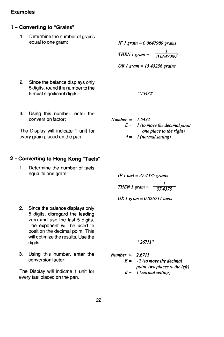
ExampleExample
Example
ExampleExample
Converting to “Grains”Converting to “Grains”
Converting to “Grains”
Converting to “Grains”Converting to “Grains”
1. Determine the number of grains equal
to one gram:
2. Since the balance displays only 5
digits, round the number to the 5 most
significant digits:
IF 1 grain = 0.0647989 grams
THEN 1 gram =
1
0.0647989
OR 1 gram = 15.43236 grains
3. Using this number, enter the conversion factor:
The display will indicate 1 unit for every
grain placed on the platform.
“15432”
Number = 1.5432
E = 1 (to move the decimal point
one place to the right)
d = 1 (normal setting)
26
Page 68

Averaging LevelAveraging Level
Averaging Level
Averaging LevelAveraging Level
Averaging level compensates for vibration or excessive air currents. During operation, the balance continually takes
weight readings from the weighing cell.
Successive readings are then digitally processed to achieve a stabilized display.
Use this submenu to specify how much
processing you need to obtain stable results.
NOTENOTE
NOTE: Averaging level does not affect
NOTENOTE
balance accuracy.
AVERAGING LEVELAVERAGING LEVEL
AVERAGING LEVEL
AVERAGING LEVELAVERAGING LEVEL
AL 0 Reduced stability, fastest
stabilization time.
AL 1AL 1
Normal stability, normalNormal stability, normal
AL 1
Normal stability, normal
AL 1AL 1
Normal stability, normalNormal stability, normal
stabilization timestabilization time
stabilization time
stabilization timestabilization time
..
.
..
Select one of three averaging levels using
the adjacent table as a guide.
To view or change the averaging level:
1. Access the AL submenu.
2. Press
ting.
3. Press
4. Press
setting, when released, AL will be
displayed again.
to display the current set-
to change the setting.
to accept the displayed
AL 2 More stability, slow
stabilization time.
27
Page 69

Stability RangeStability Range
Stability Range
Stability RangeStability Range
The stability range specifies how much a
displayed weight may change while the
stability indicator (unit indicator) remains
ON. When displayed weight changes
beyond the allowable range, the stability
indicator turns OFF indicating an unstable
condition. Portable
permit you to select one of four stability
ranges (in divisions) as shown in the table.
NOTENOTE
NOTE: When the RS232 interface is
NOTENOTE
configured to print stable data only, the
stability range also governs data output.
Displayed data will only be output if it is
within the selected stability range.
To view or change the stability range:
1. Access the Stb submenu to display
the current setting.
Advanced
balances
STABILITY RANGESTABILITY RANGE
STABILITY RANGE
STABILITY RANGESTABILITY RANGE
..
.5d Smallest range: stability indi-
..
cator is ON only when displayed weight is within .5 divisions.
1d1d
Normal range.Normal range.
1d
Normal range.
1d1d
Normal range.Normal range.
2d Increased range.
5d Largest range: stability indi-
cator is ON with displayed
weight changes up to 5 divisions.
2. Press to display the current setting.
3. Press
4. Press
setting, when released, Stb will be
displayed again.
to change the setting.
to accept the displayed
28
Page 70

Auto-ZeroAuto-Zero
Auto-Zero
Auto-ZeroAuto-Zero
Auto-Zero minimizes the effects of temperature changes and shift on the zero
reading. By defining a threshold level in
divisions, the balance maintains the zero
display until the threshold is exceeded.
This submenu permits you to select one of
three threshold levels, or turn the feature
OFF. Auto-zero only functions when the
display reads zero.
To view or change the auto-zero setting:
1. Access the Auto0 submenu.
AUTO ZEROAUTO ZERO
AUTO ZERO
AUTO ZEROAUTO ZERO
OFF Turns Auto-Zero OFF.
.5d.5d
Sets threshold to .5 divisions.Sets threshold to .5 divisions.
.5d
Sets threshold to .5 divisions.
.5d.5d
Sets threshold to .5 divisions.Sets threshold to .5 divisions.
1d Sets threshold to 1 division.
3d Sets threshold to 3 divisions.
2. Press
ting.
3. Press
4. Press
setting, when released, Auto0 will be
displayed again.
to display the current set-
to change the setting.
to accept the displayed
29
Page 71

Parts Counting Error LevelParts Counting Error Level
Parts Counting Error Level
Parts Counting Error LevelParts Counting Error Level
The parts counting error level is based on
the resolution (readability) of the particular
model balance and sample weight. The
adjacent table lists error levels that you
can choose from.
To view, change or disable the parts counting error level:
1. Access the PCErr submenu.
2. Press
to display the current set-
ting.
ERROR LEVELSERROR LEVELS
ERROR LEVELS
ERROR LEVELSERROR LEVELS
OFFOFF
OFF
OFFOFF
1 % ±1 % acceptable error.
2.5 % ±2.5 % acceptable error.
5 % ±5.0 % acceptable error.
Disables error level limits.Disables error level limits.
Disables error level limits.
Disables error level limits.Disables error level limits.
3. Press
4. Press
to change the setting.
to accept the displayed
setting, when released, PCErr will be
displayed again.
30
Page 72

Auto OffAuto Off
Auto Off
Auto OffAuto Off
Auto Off permits the selection of either
OFF, 60 seconds, 120 seconds or 180
seconds. When this function is selected,
the balance will turn off if it is idle for the
selected period of time (60, 120 or 180
seconds). This feature is especially useful
when the balance is operated from internal batteries.
To view, change or disable the auto off
feature:
1. Access the A. Off submenu.
TIMER SETTINGSTIMER SETTINGS
TIMER SETTINGS
TIMER SETTINGSTIMER SETTINGS
OFFOFF
OFF
OFFOFF
60 Turns off in 60 seconds.
120 Turns off in 120 seconds.
180 Turns off in 180 seconds.
Disables feature.Disables feature.
Disables feature.
Disables feature.Disables feature.
2. Press
to display the current set-
ting.
3. Press
4. Press
to change the setting.
to accept the displayed
setting. When is released,
A. Off will be displayed again.
EndEnd
End
EndEnd
You must use End to exit the Setup menu.
Changes you make in the Setup menuChanges you make in the Setup menu
Changes you make in the Setup menu
Changes you make in the Setup menuChanges you make in the Setup menu
are only stored in memory if you useare only stored in memory if you use
are only stored in memory if you use
are only stored in memory if you useare only stored in memory if you use
End.End.
End.
End.End.
To exit the Setup menu and store your
settings, press
played. When
when END is dis-
is released, the bal-
ance will be returned to normal weighing
operations.
31
Page 73

CALIBRATION LOCK-OUT PROTECTIONCALIBRATION LOCK-OUT PROTECTION
CALIBRATION LOCK-OUT PROTECTION
CALIBRATION LOCK-OUT PROTECTIONCALIBRATION LOCK-OUT PROTECTION
Access to the Calibration menu can be disabled using the lock out switch located on
the right side of the balance.
1. Turn the balance off and unplug the power cord.
2. Locate the access hole on the right side of the balance where the switch is located
and remove the plug from the hole.
3. Using a small screwdriver, slide the switch to the front of the balance for LOCKED
or towards the rear of the balance for UNLOCKED.
4. Replace the plug in the access hole.
5. Plug in the power cord and turn on the balance.
LOCK OUT
SWITCH
LOCK OUT SWITCH
ACCESS HOLE
UNLOCK
LOCK
32
Page 74

CARE AND MAINTENANCECARE AND MAINTENANCE
CARE AND MAINTENANCE
CARE AND MAINTENANCECARE AND MAINTENANCE
To keep the balance operating properly, the housing and platform should be kept
clean and free from foreign material. If necessary, a cloth dampened with a mild
detergent may be used. Keep calibration masses in a safe dry place.
Unplug the AC Adapter when not in use. For long term storage, remove the batteries.
TROUBLESHOOTINGTROUBLESHOOTING
TROUBLESHOOTING
TROUBLESHOOTINGTROUBLESHOOTING
SYMPTOM
No Display
LO BAT Indicator
- - -
Incorrect Weight
Reading
Calibration Procedure does not work
Unable to display
weight in a particular weighing unit
PROBABLE CAUSE
Power Adapter not
connected.
Batteries are dead.
Batteries are weak.
Underweight Indicator,
platform may be off of
balance.
Balance was not
rezeroed before weighing.
Balance has not been
properly calibrated.
Incorrect weights being
used.
Weighing unit not
enabled in Setup menu.
REMEDY
Connect Power Adapter.
Replace batteries.
Replace batteries.
Replace platform.
Press ON TARE with no
weight on the platform,
then weigh item.
Recalibrate correctly.
Use correct weights.
Use Unit Selection submenu to set desired units
ON (see Setup menu).
Unable to access
C. UNIT in Setup
menu to enter
Conversion Factor
Balance won't store
selections made in
Setup menu
Custom Units ( ● ) not
enabled in Setup menu,
or not set to USR.
END selection was not
used to exit Setup menu.
33
Use Unit Selection submenu to set Custom Units
( ● ) to USR.
You MUST use END to
exit Setup menu and save
selections.
Page 75

Error CodesError Codes
Error Codes
Error CodesError Codes
The following list describes the various error codes which can appear on the display
and the suggested remedy.
Display DescriptionDisplay Description
Display Description
Display DescriptionDisplay Description
Err 0Err 0
Err 0 This indicates a hardware error causing an invalid checksum on calibration
Err 0Err 0
data. The balance may need recalibration, particularly linearity calibration. If
the error persists after recalibration, the balance must be serviced.
Err 1Err 1
Err 1 Sample being weighed exceeds the capacity of the balance. If error occurs
Err 1Err 1
when the sample is within the balance capacity, balance may be incorrectly
calibrated. An underload such as the platform off of the balance could also
display Err1. Recalibrate the balance.
Err 2Err 2
Err 2 This indicates a hardware error causing an internal weight signal which is too
Err 2Err 2
high. The balance must be serviced.
Err 3Err 3
Err 3 This indicates a hardware error causing an internal weight signal which is too
Err 3Err 3
low. The balance must be serviced.
Error 3 appears on the display as "- - - ". It will be sent over the RS232 interface
as "Err3" if that accessory is installed.
Err 4Err 4
Err 4 Incorrect or no calibration weight used when performing calibration procedure.
Err 4Err 4
Error will flash momentarily, then balance will use previous calibration data.
Recalibrate correctly.
Err 5Err 5
Err 5 Value is too large to display; exceeds 99999 counts. Possibly caused by an
Err 5Err 5
invalid custom unit conversion factor.
Err 6Err 6
Err 6 Custom unit conversion factor exponent and LSD choices have placed the
Err 6Err 6
decimal point off of the display. The error flashes momentarily and the new
conversion factor will not be accepted.
Err 7Err 7
Err 7 Power-on load error caused by load on platform during power-up. The display
Err 7Err 7
appears for three seconds and the balance will use previously stored calibration
data. Remove load from platform and reapply power.
Err 9Err 9
Err 9 Internal data error. Return balance for servicing.
Err 9Err 9
SERVICE INFORMATIONSERVICE INFORMATION
SERVICE INFORMATION
SERVICE INFORMATIONSERVICE INFORMATION
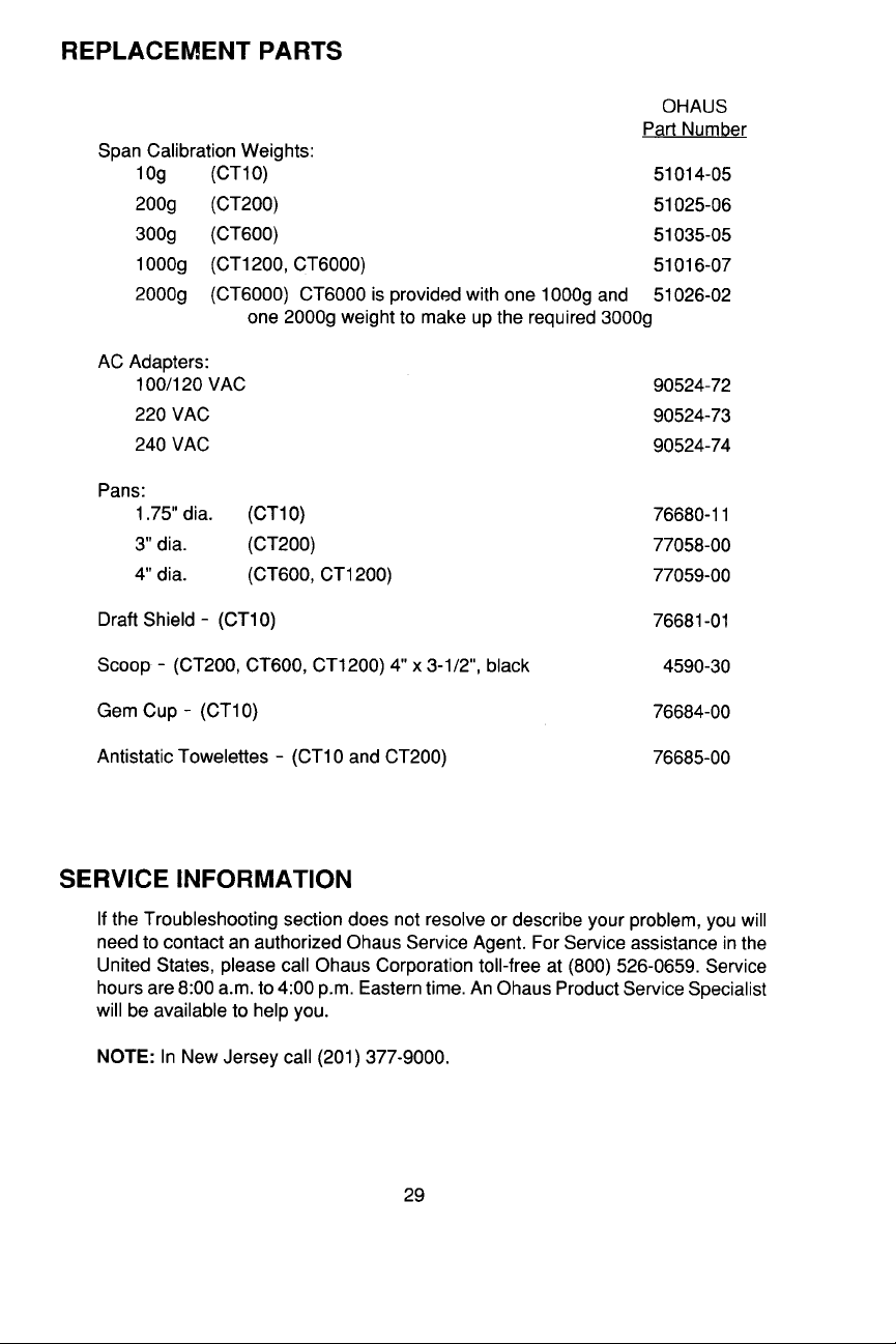
If the Troubleshooting section does not resolve or describe your problem, you will need
to contact an authorized Ohaus Service Agent. For Service assistance in the United
States, please call Ohaus Corporation toll-free at (800) 526-0659, an Ohaus Product
Service Specialist will be available to help you.
NOTE:NOTE:
NOTE: In New Jersey call (201) 377-9000.
NOTE:NOTE:
34
Page 76

PARTS INFORMATIONPARTS INFORMATION
PARTS INFORMATION
PARTS INFORMATIONPARTS INFORMATION
If you require replacement parts or would like to purchase accessories, please call
Ohaus Corporation toll-free at (800) 526-0659, an Ohaus Product Parts Specialist will
be available to help you.
REPLACEMENT PARTSREPLACEMENT PARTS
REPLACEMENT PARTS
REPLACEMENT PARTSREPLACEMENT PARTS
OHAUS
Part Number
Span Calibration Masses:
10g (CT10) 51014-05
200g (CT200) 51025-06
300g (CT600) 51035-05
AC Adapters:
100/120 V ac US Plug 90524-77
230/240 V ac European Plug 90524-75
230/240 V ac UK Plug 90524-79
240 V ac Australian Plug 90524-76
Platforms:
1.75" dia. (CT10) 76680-11
4" dia. (CT200) 77521-00
4" dia. (CT200V) 77576-01
4.75" dia. (CT600) 77261-01
4.75" dia. (CT600V) 77577-01
4.75" x 6.5" (CT1200) 77467-02
Draft Shield - (CT10) 76681-01
Scoop - (CT200, CT600, CT1200) 4" x 3-1/2", black 4590-30
Gem Cup - (CT10) 76684-00
Antistatic Towelettes - (CT10 and CT200) 76685-00
Weigh Below Hook 5227-04
35
Page 77

SECURITYSECURITY
SECURITY
SECURITYSECURITY
The balance can be secured to a stationary object using the Security Locking Cable
Accessory. The locking cable is equipped with a fastener which must be inserted in
the plugged hole in the back of the balance. The cable can be passed through the
fastener and secured to a stationary object.
ACCESSORIESACCESSORIES
ACCESSORIES
ACCESSORIESACCESSORIES
OHAUS
Part Number
RS232 Interface 77172-01
Security Locking Cable 76288-00
Span Calibration Mass Sets for CT1200 and CT6000
CT1200 - set includes one 1000g weight 76527-02
CT6000 - set includes one 1000g and one 2000g Mass 76527-00
Linearity Calibration Masses:
CT10 5g 53053-00
CT200 100g 51015-05
CT600 300g (use with 300g span mass 51035-05
provided to make 600g.)
CT1200 500g (1000g span mass also required) 51055-06
CT6000 2000g - 2 required (1000g and 2000g span 51026-02
masses also required)
Scoops:
4" x 3-1/2", gold 4590-00
4" x 3-1/2", aluminum 4590-10
1-1/2" x 2", aluminum 5076-00
2-1/4" x 3", gold 5077-00
2-1/4" x 3", black 5077-01
12" x 6", Stainless Steel, footed, (tare 190g), for CT6000 1078-03
12" x 6", Polypropylene, footed, (tare 125g), for CT6000 1101-20
Vinyl Carrying Case (used with original foam packing) 76525-02
Deluxe Hard Carrying Case 77256-01
36
Page 78

SPECIFICATIONSSPECIFICATIONS
SPECIFICATIONS
SPECIFICATIONSSPECIFICATIONS
MODELMODEL
MODEL
MODELMODEL
Capacity x Readability
grams (g) 10 x 0.002 202 x 0.01 602 x 0.1 1210 x 0.1 6010 x 0.5
ounces (oz) 0.35 x 0.0001 7.1 x 0.0005 21.2 x 0.005 42.6 x 0.005 212 x 0.02
ounces troy (oz t) 0.32 x 0.0001 6.5 x 0.0005 19.3 x 0.005 38.9 x 0.005 196 x 0.02
pennyweight (dwt) 6.4 x 0.002 130 x 0.01 387 x 0.1 778 x 0.1 3900 x 0.5
carats (ct) 50 x 0.01 999 x 0.05 3010 x 0.5 6050 x 0.5 30000 x 5
pounds (lb)
HK taels 0.2671/0.0001 5.396/0.0005 16.08/0.005 32.32/0.005 160.3/0.02
Singapore taels 0.2645/0.0001 5.344/0.0005 15.92/0.005 32.01/0.005 158.7/0.02
Taiwan taels 0.2666/0.0001 5.386/0.0005 16.05/0.005 32.26/0.005 160.0/0.02
Parts counting Standard
Custom unit Standard
Repeatability (std. dev.) (g)
Linearity (g) ±0.002 ±0.01 ±0.1 ±0.1 ±0.5
Tare range To capacity by subtraction
Over range capacity Capacity plus 9d
Stabilization time (Sec.) 3 3 2.5 2.5 2.5
Sensitivity drift (%/°C) ±0.005 ±0.003 ±0.01 ±0.003 ±0.005
Zero point drift (g/°C) ±0.002 ±0.02 ±0.2 ±0.2 ±1
Shift accuracy
(1/2 capacity, 1/2 distance) (g
Operating temperature 50° to 104°F/ 10° to 40°C
Calibration Auto calibration
Power requirements AC adapter (supplied with balance); 100, 120, 220, 240 V ac, 50/60 Hz
Typical battery life 50 hours (without optional RS232 accessory)
Display (in/cm) LCD (0.5/1.3 high)
Platform Size (in/cm) 1.75/4.4 dia. 4/10.2 dia. 4.75/12.1dia. 4.75 x 6.5/ 4.75 x 6.5/
Dimensions
(W x H x D) (in/cm) 7.0 x 2.5 x 7.7/17.8 x 6.3 x 19.6
Net weight (lb/kg) 2/0.9 1.5/0.7 1.7/0.8 2.3/1 2.3/1
Shipping weight (lb/kg) 3/2 4/2 4/2 4/2 4/2
CT10 CT10
CT10
CT10 CT10
0.002 0.01 0.07 0.1 0.5
)
±0.002 ±0.01 ±0.1 ±0.1 ±0.5
CT200CT200
CT200
CT200CT200
0.44 x 0.0001
or 8 AA Batteries (not included)
CT600CT600
CT600
CT600CT600
1.32 x 0.0002 2.6 x 0.0002 13.4 x 0.002
CT1200CT1200
CT1200
CT1200CT1200
12.1 x 16.5 12.1 x 16.5
CT6000CT6000
CT6000
CT6000CT6000
37
Page 79

LIMITED WARRANTYLIMITED WARRANTY
LIMITED WARRANTY
LIMITED WARRANTYLIMITED WARRANTY
Ohaus products are warranted against defects in materials and
workmanship from the date of delivery through the duration of the
warranty period. During the warranty period Ohaus will repair, or, at its
option, replace any component(s) that proves to be defective at no
charge, provided that the product is returned, freight prepaid, to
Ohaus.
This warranty does not apply if the product has been damaged by
accident or misuse, exposed to radioactive or corrosive materials, has
foreign material penetrating to the inside of the product, or as a result
of service or modification by other than Ohaus. In lieu of a properly
returned warranty registration card, the warranty period shall begin on
the date of shipment to the authorized dealer. No other express or
implied warranty is given by Ohaus Corporation. Ohaus Corporation
shall not be liable for any consequential damages.
As warranty legislation differs from state to state and country to
country, please contact Ohaus or your local Ohaus dealer for further
details.
38
Page 80

Ohaus Corporation
29 Hanover Road,
Florham Park, NJ 07932, USA
Tel: (973) 377-9000,
Fax: (973) 593-0359
With offices worldwide.
P/N 77145-03 R0698 © Ohaus Corporation 1998, all rights reserved.
39
Page 81

Ohaus Corporation
29 Hanover Road
Florham Park NJ
07932-0900
CT SERIESCT SERIES
CT SERIES
CT SERIESCT SERIES
RS232 INTERFRS232 INTERF
RS232 INTERF
RS232 INTERFRS232 INTERF
KITKIT
KIT
KITKIT
AA
A
AA
CECE
CE
CECE
For use with Models
CT10, CT200, CT600, CT600L
CT1200 and CT6000
Instruction ManualInstruction Manual
Instruction Manual
Instruction ManualInstruction Manual
NOTICE:NOTICE:
NOTICE: THIS EQUIPMENT HAS BEEN TESTED AND FOUND TO COMPLY WITH THE LIMITS FOR
NOTICE:NOTICE:
A CLASS A DIGITAL DEVICE, PURSUANT TO PART 15 OF THE FCC RULES.
THESE LIMITS ARE DESIGNED TO PROVIDE REASONABLE PROTECTION AGAINST HARMFUL
INTERFERENCE WHEN THE EQUIPMENT IS OPERATED IN A COMMERCIAL ENVIRONMENT.
THIS EQUIPMENT GENERATES, USES, AND CAN RADIATE RADIO FREQUENCY ENERGY AND,
IF NOT INSTALLED AND USED IN ACCORDANCE WITH THE INSTRUCTION MANUAL, MAY CAUSE
HARMFUL INTERFERENCE TO RADIO COMMUNICATIONS. OPERATION OF THIS EQUIPMENT IN
A RESIDENTIAL AREA IS LIKELY TO CAUSE HARMFUL INTERFERENCE IN WHICH CASE THE
USER WILL BE REQUIRED TO CORRECT THE INTERFERENCE AT HIS OWN EXPENSE.
THIS DIGITAL APPARATUS DOES NOT EXCEED THE CLASS A LIMITS FOR RADIO NOISE EMISSIONS FROM DIGITAL APPARATUS AS SET OUT IN THE INTERFERENCE-CAUSING EQUIPMENT
STANDARD ENTITLED “DIGITAL APPARATUS”, ICES-003 OF THE DEPARTMENT OF COMMUNICATIONS.
CET APPAREIL NUMERIQUE RESPECTE LES LIMITES DE BRUITS RADIOELECTRIQUES
APPLICABLES AUX APPAREILS NUMERIQUES DE CLASSE A PRESCRITES DANS LA NORME
SUR LE MATERIEL BROUILLEUR : “APPAREILS NUMERIQUES”, NMB-003 EDICTEE PAR LE
MINISTRE DES COMMUNICATIONS.
Unauthorized changes or modifications to this equipment are not permitted.
1
Page 82

INTRODUCTIONINTRODUCTION
INTRODUCTION
INTRODUCTIONINTRODUCTION
The RS232 Interface Accessory is a bidirectional interface which enables Portable
Advanced
with an RS232 serial port. The interface assembly is easily installed in the balance and
communication parameters are configured using the Print menu after installation.
INSTALLATIONINSTALLATION
INSTALLATION
INSTALLATIONINSTALLATION
Electronic Balances to communicate with a printer or computer equipped
Use the following procedure to install the
RS232 Interface accessory.
CAUTIONCAUTION
CAUTION
CAUTIONCAUTION
TO PREVENT DAMAGE TO THE BALANCE, BE CERTAIN THAT POWER IS
DISCONNECTED BEFORE REMOVING
THE COVER.
1. Disconnect power to the balance.
2. Remove the Platform from the balance, and turn the balance upside
down. (Do not remove Platform on
CT6000 Models.)
3. Remove batteries if installed.
4. The bottom plate is held by four
screws, one located in each corner.
Remove the four screws and lift off
the bottom plate.
5. At the rear of the balance, a protective
label is provided which covers the
hole for the 9-pin RS232 connector.
Peel off the label to expose the hole.
REMOVE 4 COVER SCREWS
REMOVE LABEL
6. The circuit board in the balance contains a circuit connector. Obtain the
RS232 Interface Accessory and carefully install the ribbon connector from
the Interface onto the edge of the
main circuit board as shown.
CONNECTOR FROM RS232 INTERFACE
2
Page 83

7. Place the RS232 circuit board and
connector assembly in the balance
so that the 9-pin connector fits through
the hole.
8. Fasten the Interface assembly to the
balance using the two screws provided with the Interface.
9 Replace the bottom plate and fasten
with the 4 screws previously removed.
INSERT CIRCUIT BOARD
AS SHOWN
10. Install the batteries (if removed) or
AC Adapter.
11. Replace the platform.
Cable ConnectionsCable Connections
Cable Connections
Cable ConnectionsCable Connections
It is recommended to use an Ohaus cable,
however, you may configure your own.
On the rear of the balance, a 9-pin subminiature “D” connector is provided for interfacing to other devices. The pinout and pin
connections are shown in the adjacent
illustration.
The balance will not output any data unless pin 5 (CTS) is held in an ON state (+3
to +15 V dc). Interfaces not utilizing the
CTS handshake may tie pin 5 to pin 6 to
defeat it.
Connect the cable from the balance to the
external device.
If communication parameters of the external device match the factory settings, the
Interface is ready for use. Refer to Printing. If not, refer to Configuring the Print
Menu to change the interface parameters.
FASTEN SCREWS
TARE *
PRINT *
1 Make no connection
2 Data Out (TXD)
3 Data In (RXD)
4* Tare (External signal)
5 Clear To Send (CTS)
6 Data Terminal Ready (DTR)
7 Ground
8 Request To Send (RTS)
9* Print (External signal)
* External PRINT and/or TARE
switches may be installed as shown
in the diagram. Momentary contact switches must be used.
3
Page 84

PRINTINGPRINTING
PRINTING
PRINTINGPRINTING
When the Interface is installed,
the switch on the balance can initate
print commands as follows:
1. Short press when only
2. Slightly extended press when
3. Longer press turns the balance
The display indicates -P- and the external device will print. Data output is in the format
shown under the P command in the RS232 Command Table.
Data output can also be initiated as follows:
1.Using the Auto Print feature.
2.Sending a print command (“P”) from a computer.
3.Using an external print switch.
When the interface is connected to a computer, two way communication between the
computer and balance is possible using the commands outlined in the RS232
Command Table.
oneone
one
measuring unit is set on.
oneone
more than onemore than one
more than one
more than onemore than one
offoff
off
.
offoff
measuring unit is on.
4
Page 85

CONFIGURING THE PRINT MENUCONFIGURING THE PRINT MENU
CONFIGURING THE PRINT MENU
CONFIGURING THE PRINT MENUCONFIGURING THE PRINT MENU
The Print menu is used to configure the RS232 Interface parameters and customize
the balance’s print functions for your requirements. The following illustration shows
the sequence in which submenus appear on the Print menu.
PRINT MENU
RESET
YES/NO
BAUD RATE
300, 1200,
4800, 9600
DATA BITS**
77
7 or 8
77
PARITY BIT**
Odd, Even,
STOP BITS**
1 or
AUTO PRINT
continuous, on stability,
OFFOFF
OFF
OFFOFF
24002400
2400,
24002400
NoneNone
None
NoneNone
22
2
22
Resets to original factory settings:
Baud Rate: 2400
Data Bits: 7
Parity Bit: None
Stop Bit: 2
Auto Print: OFF
Stable Data Output
Only: OFF
STABLE DATA OUTPUT ONLY *
END
ON or
OFFOFF
OFF
OFFOFF
Must be used to exit
and store changes
made.
* Not available on Legal for Trade models. Original factory settings apply.
**The total number of bits for Data, Parity and Stop must equal 9 or 10.
To access the Print menu, press and hold until Print appears, then release it.
Use these buttons to step through the menu and make selections:
next
selection
select
displayed item
5
Page 86

RS232 COMMAND TABLERS232 COMMAND TABLE
RS232 COMMAND TABLE
RS232 COMMAND TABLERS232 COMMAND TABLE
Only the characters shown in the following table are acknowledged by the balance. Any other
commands not shown in the table, balance responds with ES syntax error. Commands sent to
the balance must be terminated with a carriage return (CR) or carriage return-line line feed
(CRLF). Data output by the balance is always terminated with a carriage return - line feed (CRLF).
CommandCommand
Command
CommandCommand
CharacterCharacter
Character
CharacterCharacter
<Esc> D<Esc> D
<Esc> D Sets all balance menu selections to the factory defaults.
<Esc> D<Esc> D
PP
P Print display data in the following format:
PP
??
? Print display Unit in the following format:
??
MM
M This command has the same effect as pressing the left button (OFF
MM
TT
T This command has the same effect as pressing the Right button (On
TT
EE
E Exit parts counting mode.
EE
L*L*
L* Start a 3 point Linearity Calibration.
L*L*
DescriptionDescription
Description
DescriptionDescription
1 2 3 4 5 6 7 8 9 10 11 12 13 14
+ display value Sp units ? Cr Lf Sp=Space
(field) units stability Cr Lf
(# of char) 3 1 1 1
MODE) on the front panel.
TARE) on the front panel.
C*C*
C* Start Span Calibration.
C*C*
VV
V Print software version in the format: "CT V-.-".
VV
NN
N Toggle automatic error message printing ON or OFF. Current status
NN
0D/1D0D/1D
0D/1D Disable/Enable a 1 second delay in the balance's response to a "P"
0D/1D0D/1D
0S/1S0S/1S
0S/1S * Disable/Enable the Stable Data Only printing feature. This is equiva-
0S/1S0S/1S
nZ*, n=0,1,2,3nZ*, n=0,1,2,3
nZ*, n=0,1,2,3 Set Auto Zero Tracking to OFF, .5d, 1d or 3d. This is the equivalent
nZ*, n=0,1,2,3nZ*, n=0,1,2,3
nnAnnA
nnA Set Auto Print feature to nn. This is equivalent to the Auto.P sub-menu
nnAnnA
* Command is not available on Legal for Trade models.
after executing the command is shown as ON or OFF. Default is ON.
command.
lent to the StAbL sub-menu of the Print menu.
to the Auto.0 sub-menu of the Setup menu.
of the Print menu with the feature of "Interval Print" added.
nn=0, Off
nn=S, On Stable
nn=C, Continuous
nn=1 -99, Set interval to nn seconds.
6
Page 87

SERVICE INFORMATIONSERVICE INFORMATION
SERVICE INFORMATION
SERVICE INFORMATIONSERVICE INFORMATION
For Service assistance in the United States, please call Ohaus Corporation toll-free at
(800) 526-0659. An Ohaus Product Service Specialist will be available to help you.
LIMITED WARRANTYLIMITED WARRANTY
LIMITED WARRANTY
LIMITED WARRANTYLIMITED WARRANTY
Ohaus products are warranted against defects in materials and
workmanship from the date of delivery through the duration of the
warranty period. During the warranty period Ohaus will repair, or, at its
option, replace any component(s) that proves to be defective at no
charge, provided that the product is returned, freight prepaid, to
Ohaus.
This warranty does not apply if the product has been damaged by
accident or misuse, exposed to radioactive or corrosive materials, has
foreign material penetrating to the inside of the product, or as a result
of service or modification by other than Ohaus. In lieu of a properly
returned warranty registration card, the warranty period shall begin on
the date of shipment to the authorized dealer. No other express or
implied warranty is given by Ohaus Corporation. Ohaus Corporation
shall not be liable for any consequential damages.
As warranty legislation differs from state to state and country to
country, please contact Ohaus or your local Ohaus dealer for further
details.
7
Page 88

Ohaus Corporation
29 Hanover Road,
Florham Park, NJ 07932, USA
Tel: (973) 377-9000,
Fax: (973) 593-0359
With offices in England, France, Germany, Italy, Spain, Poland, Mexico, Japan,
Korea and China.
P/N 77171-02 R1198 © Ohaus Corporation 1996, 1998 all rights reserved.
8
Page 89

Page 90

Page 91

Page 92

Page 93

Page 94

Page 95

Page 96

Page 97

Page 98

Page 99

Page 100

 Loading...