

Page 1

ANALYTICAL
Menu
Menu
Electronic Balances
Models
AP1 10, AP210, AP310, AP250D,
AP1 10E, AP210E, AP310E and
AP250E
Plus
Instruction Manual
Page 2

NOTE: THIS EQUIPMENT HAS BEEN TESTED AND FOUND TO COMPLY WITH THE LIMITS FOR
Menu
Menu
A CLASS A DIGITAL DEVICE, PURSUANT TO PART 15 OF THE FCC RULES.
THESE LIMITS ARE DESIGNED TO PROVIDE REASONABLE PROTECTION AGAINST HARMFUL
INTERFERENCE WHEN THE EQUIPMENT IS OPERATED IN A COMMERCIAL ENVIRONMENT.
THIS EQUIPMENT GENERATES, USES, AND CAN RADIATE RADIO FREQUENCY ENERGY AND,
IF NOT INSTALLED AND USED IN ACCORDANCE WITH THE INSTRUCTION MANUAL, MAY
CAUSE HARMFUL INTERFERENCE TO RADIO COMMUNICATIONS. OPERATION OF THIS EQUIPMENT IN A RESIDENTIAL AREA IS LIKELY TO CAUSE HARMFUL INTERFERENCE IN WHICH
CASE THE USER WILL BE REQUIRED TO CORRECT THE INTERFERENCE AT HIS OWN EXPENSE.
THIS DIGITAL APPARATUS DOES NOT EXCEED THE CLASS A LIMITS FOR RADIO NOISE
EMISSIONS FROM DIGITAL APPARATUS AS SET OUT IN THE INTERFERENCE-CAUSING EQUIPMENT STANDARD ENTITLED “DIGITAL APPARATUS”, ICES-003 OF THE DEPARTMENT OF
COMMUNICATIONS.
CET APPAREIL NUMERIQUE RESPECTE LES LIMITES DE BRUITS RADIOELECTRIQUES
APPLICABLES AUX APPAREILS NUMERIQUES DE CLASSE A PRESCRITES DANS LA NORME
SUR LE MATERIEL BROUILLEUR: “APPAREILS NUMERIQUES”, NMB-003 EDICTEE PAR LE
MINISTRE DES COMMUNICATIONS.
Unauthorized changes or modifications to this equipment are not permitted.
The exclamation
point within the triangle is a warning
sign alerting you of
important instructions accompanying the product.
Page 3
TABLE OF CONTENTS
Menu
Menu
INTRODUCTION ............................................................................................................. 1
DESCRIPTION ................................................................................................................ 1
FEATURES ..................................................................................................................... 1
UNPACKING ................................................................................................................... 2
INSTALLATION ............................................................................................................... 3
Environment ............................................................................................................. 3
Weigh Below Hook ................................................................................................... 3
Leveling the Balance ................................................................................................ 4
Installing the Pan Assembly ..................................................................................... 4
In-Service Cover....................................................................................................... 4
RS232 Interface ....................................................................................................... 5
Hardware .............................................................................................................. 5
Output Formats..................................................................................................... 5
RS232 Commands ................................................................................................... 5
Connecting Power .................................................................................................... 8
Spare Fuse............................................................................................................... 8
Self Test ................................................................................................................... 8
OPERATION ................................................................................................................... 9
Switch Functions ...................................................................................................... 9
Symbols Used for Operation of the Balance .......................................................... 10
Navigating the Menus............................................................................................. 11
Operational Guide/Index ........................................................................................ 12
Turning the Balance On ......................................................................................... 13
Display Indications ................................................................................................. 13
Stabilization ............................................................................................................ 14
Auto Range (AP250D and E Only)......................................................................... 14
Weighing ................................................................................................................ 14
Taring ..................................................................................................................... 14
Percent Weighing ................................................................................................... 15
Parts Counting........................................................................................................ 16
Check Weighing ..................................................................................................... 17
Animal Weighing .................................................................................................... 18
Fill Guide ................................................................................................................ 19
Reference Weight ............................................................................................... 19
i
Page 4
Reference Number ............................................................................................. 20
Menu
Menu
High Point............................................................................................................... 20
Printing Data........................................................................................................... 21
Time and Date .................................................................................................... 21
List ...................................................................................................................... 22
Automatic Calibration Printout ............................................................................ 23
User Calibration Printout .................................................................................... 23
Calibration Test Printout ..................................................................................... 23
Statistics Printout ................................................................................................ 24
Sampling............................................................................................................. 24
Percent Weighing ............................................................................................... 25
Parts Counting .................................................................................................... 25
Check Weighing ................................................................................................. 26
FillGuide
MENUS.......................................................................................................................... 27
MENU LOCK-OUT PROTECTION................................................................................ 28
CALIBRATION MENU ................................................................................................... 29
Calibration Menu Protection ................................................................................... 29
Auto Calibration...................................................................................................... 29
User Calibration...................................................................................................... 30
Cal Test .................................................................................................................. 31
Cal End................................................................................................................... 31
TM
........................................................................................................... 26
USER MENU ................................................................................................................. 32
User Menu Protection............................................................................................. 32
Reset ...................................................................................................................... 32
Averaging Level...................................................................................................... 33
Stability Range ....................................................................................................... 33
Auto-Zero ............................................................................................................... 34
Dual Range Function.............................................................................................. 34
Exiting User Menu .................................................................................................. 34
ii
Page 5
SETUP MENU ............................................................................................................... 35
Menu
Menu
Setup Menu Protection........................................................................................... 36
Reset ...................................................................................................................... 36
Type Approved/LFT................................................................................................ 37
Unit Selection ......................................................................................................... 37
Functions................................................................................................................ 38
Statistics ................................................................................................................. 39
Net.......................................................................................................................... 40
Custom Unit or Volume Selection .......................................................................... 40
Good Laboratory Practices..................................................................................... 42
Parts Counting Error............................................................................................... 43
Check Weighing Options........................................................................................ 43
Sample Displays..................................................................................................... 44
Animal Weighing Options ....................................................................................... 46
Fill Option ............................................................................................................... 46
Time ....................................................................................................................... 47
Adjust ..................................................................................................................... 48
Date........................................................................................................................ 49
Lockswitch.............................................................................................................. 50
List.......................................................................................................................... 50
Exit Setup Menu ..................................................................................................... 50
PRINT MENU ................................................................................................................ 51
Print Menu Protection............................................................................................. 51
Reset ...................................................................................................................... 52
Communication ...................................................................................................... 52
Baud Rate........................................................................................................... 53
Data Bits ............................................................................................................. 53
Parity................................................................................................................... 54
Stop Bits ............................................................................................................. 54
Good Laboratory Practices (GLP) .......................................................................... 54
Print Options........................................................................................................... 55
Auto Print Feature .............................................................................................. 55
Initialize............................................................................................................... 56
iii
Page 6
Print Stable Data Only ........................................................................................ 57
Menu
Menu
Print Numeric Data Only ..................................................................................... 57
Time.................................................................................................................... 58
Date .................................................................................................................... 58
Reference ........................................................................................................... 58
Difference ........................................................................................................... 59
List ...................................................................................................................... 59
CARE AND MAINTENANCE......................................................................................... 60
TROUBLESHOOTING .................................................................................................. 60
Error Codes List ..................................................................................................... 61
SERVICE INFORMATION............................................................................................. 63
REPLACEMENT PARTS............................................................................................... 63
ACCESSORIES............................................................................................................. 63
SPECIFICATIONS......................................................................................................... 64
DECLARATION OF CONFORMITY.............................................................................. 65
LIMITED WARRANTY................................................................................................... 69
iv
Page 7
INTRODUCTION
Menu
Menu
INTRODUCTION
This manual covers Installation, Operation and Troubleshooting for the Ohaus ANALYTICAL Plus Series of Electronic balances, Models AP110, AP210, AP310, AP250D, AP110E,
AP210E, AP310E and AP250E. Suffixes after the basic model number are: D = Moveable
FineRange
Min, Class, etc.) on a serial number plate located on the side of the balance. To ensure proper
operation of the balance, please read this manual completely.
TM
and E= Type Approved with CE conformance and bear official markings (Max,
DESCRIPTION
The Ohaus ANALYTICAL Plus Series balances are high precision weighing instruments,
designed to be versatile, accurate, easy to operate and will provide years of service with
virtually no maintenance. The Analytical Plus series is constructed using a die-cast
aluminum base finished with a durable corrosion resistant epoxy powder paint. The weighing
area is protected from air currents by a draft shield. It contains solid-state precision
electronics PC boards, and a seven and a half, 0.5 inch digit, Vacuum Fluorescent display.
Each balance operates through a series of menus which enhances operation. A built in
lockswitch prevents preset settings from being changed.
FEATURES
Analytical Plus balances contain four main display menus which enable you to calibrate and
configure the balance for specific operating requirements. MENU When
pressed and released with MENU displayed, allows access to the calibration, user, setup
and print menus.
ON
TARE
switch is
CALIBRATION Menu - Allows the balance to be calibrated by using either Auto, User or
Test calibration methods. The test function is used to verify the last calibration.
USER Menu - Allows the balance to be set for environmental conditions. Reset,
averaging level, stability range and auto-zero functions can be set.
SETUP Menu - Allows the balance to be customized for specific weighing functions.
PRINT Menu - Allows the selection of parameters under which the balance will interface
to a computer or a printer.
Each of these menus contain selectable parameters which can be entered via the front panel
switches. Storing of the parameters is accomplished by selecting at the completion of all
selections in a particular menu. For a detailed description of each feature, refer to the
individual menus in this manual.
1
Page 8
INSTALLATION
Menu
Menu
UNPACKING
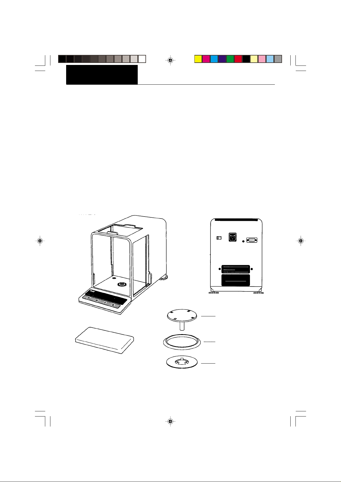
Your ANALYTICAL Plus balance was shipped with the following items:
• Pan assembly (including pan, shield, ring and assembly instructions)
• In-service cover
• AC power cord
• Spare fuse
• Instruction manual
• Warranty card
Remove the contents from the carton and carefully remove all packing material. It is
recommended to save the carton and packing material for storing and/or transporting the
balance. Verify that all of the components have been included and there has been no
damage during shipment.
ANALYTICAL
BALANCE
In-Service Cover
Plus
REAR VIEW
Pan
Ring
Shield
2
Page 9
INSTALLATION
Menu
Menu
INSTALLATION
Environment
The balance should always be used in an environment which is free from excessive air
currents, corrosives, vibration, and temperature or humidity extremes. These factors will
affect displayed weight readings.
DO NOT install the balance:
• next to open windows or doors causing drafts or rapid temperature changes.
• near air conditioning or heat vents.
• near vibrating, rotating or reciprocating equipment.
• near magnetic fields or devices that may generate magnetic fields (i.e. motors, alterna-
tors, etc.)
• on an unlevel work surface.
Install the balance in the location where it will be used before proceeding.
Weigh Below Hook
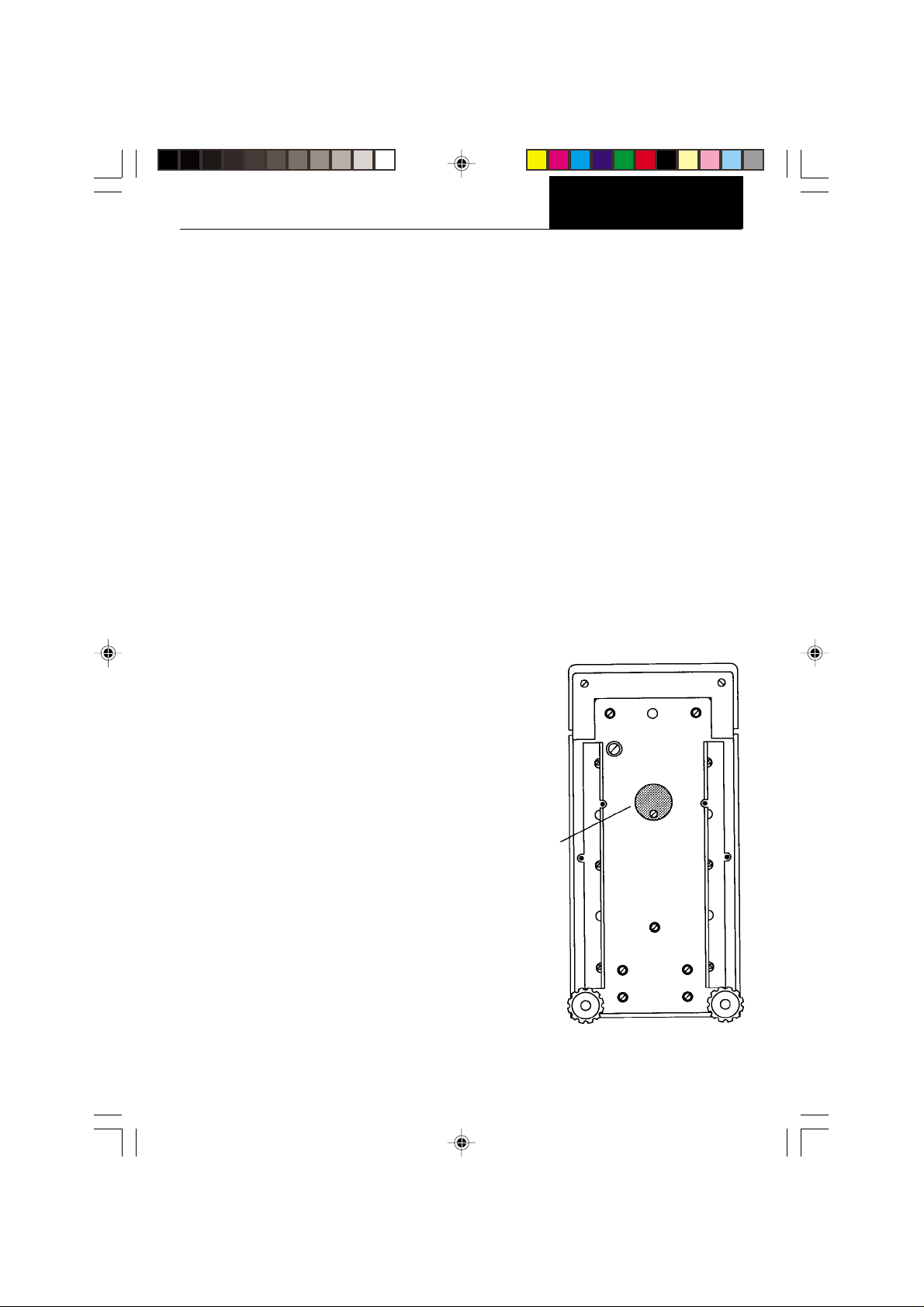
A weigh below hook is provided inside the
bottom cover under the protective plate
shown in the illustration.
To access the weigh below hook, carefully turn the balance on it's side, loosen
the screw which secures the cover plate,
rotate the plate to clear the hole, then
secure the plate in that position. Return
the balance to an upright position. Mount
the balance on a stable, level elevated
platform and install a hook.
Weigh Below
Hook Cover
Plate
3
Page 10
INSTALLATION
Menu
Menu
Leveling the Balance
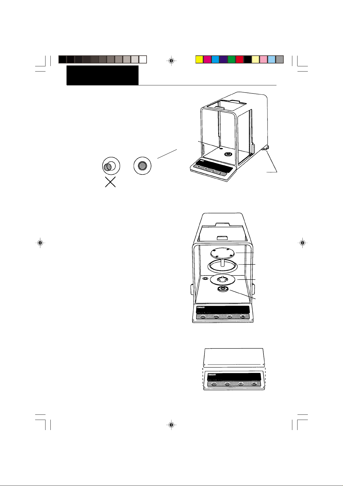
The balance is equipped with a level indicator on
the floor of the weighing chamber and two
adjustable leveling feet at the rear. Adjust the
leveling feet until the bubble appears in the
center circle of the level indicator.
Installing the Pan Assembly
1. Place the shield onto the keyed bushing
and press it down into place. The bent tabs
must be facing upward and the shield should
be flat against the chamber floor.
Level
Indicator
Leveling
Feet
2. Place the ring over the shield. The lip on the
bottom of the ring should fit against the
shield to keep it from moving.
3. Insert the pan in the load receiver hole,
matching the key on the pan shaft with the
slot in the hole. Gently press the pan down
into place.
In-Service Cover
Place the cover snugly over the display unit.
Pan
Ring
Shield
Keyed
Bushing
4
Page 11
INSTALLATION
Menu
Menu
RS232 INTERFACE
ANALYTICAL Plus balances are equipped with a bi-directional RS232 compatible interface
for communication with printers and computers. When the balance is connected directly to
a printer, displayed data can be output at any time by simply pressing PRINT, or by using
the Auto Print feature.
Connecting the balance to a computer enables you to operate the balance from the
computer, as well as receive data such as displayed weight, weighing mode, stability status,
etc.
The following sections describe the hardware and software provided with the balance.
Hardware
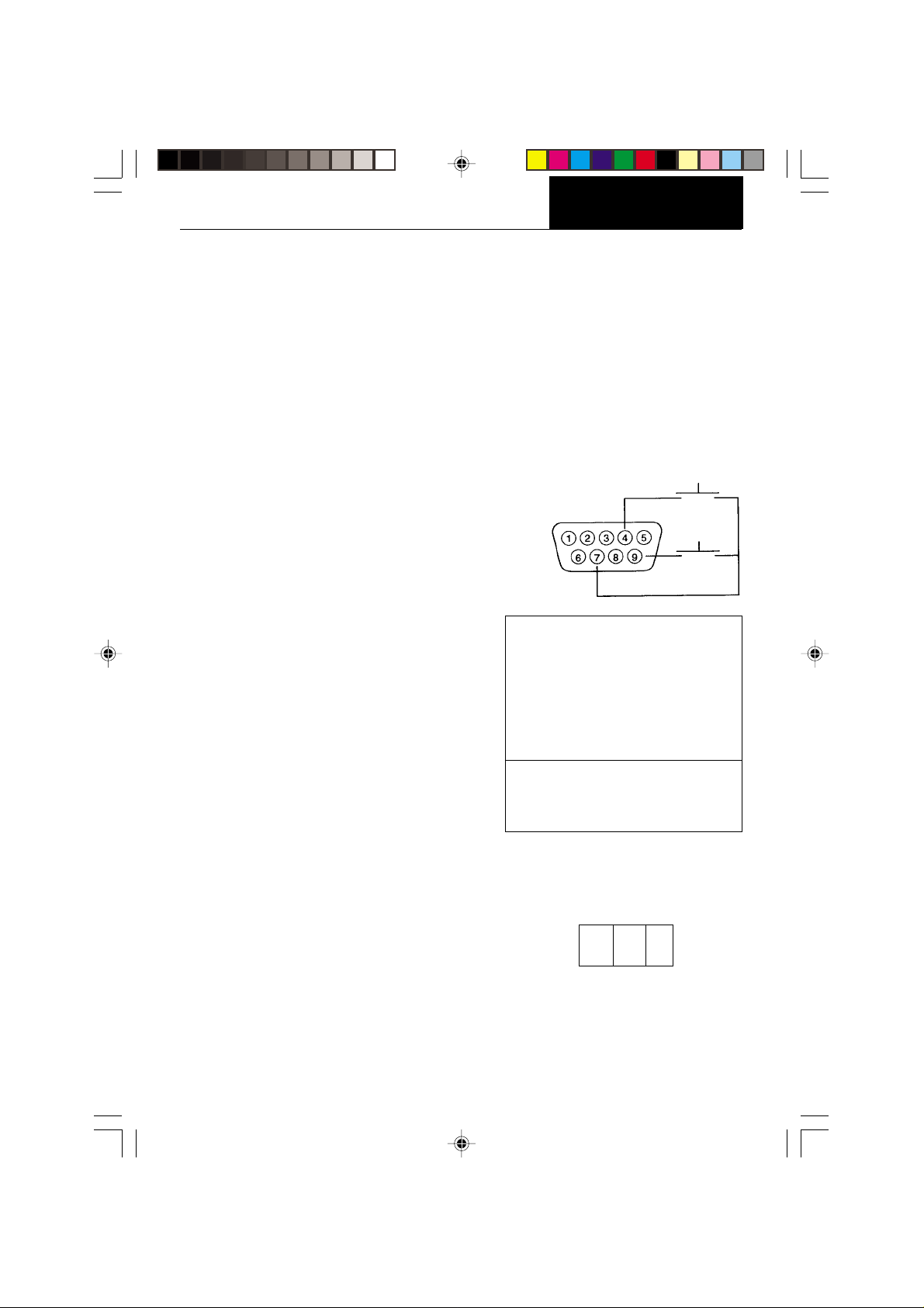
On the rear of the balance, a 9-pin subminiature “D” connector is provided for interfacing to
other devices. The pinout and pin connections
are shown in the adjacent illustration.
The balance will not output any data unless pin
5 (CTS) is held in an ON state (+3 to +15 V dc).
Interfaces not utilizing the CTS handshake
may tie pin 5 to pin 6 to defeat it.
Output Formats
Data output can be initiated in one of three
ways: 1) By pressing PRINT; 2) Using the Auto
Print feature; 3) Sending a print command
(“P”) from a computer.
The output format is illustrated in the RS232
command table which follows.
RS232 Commands
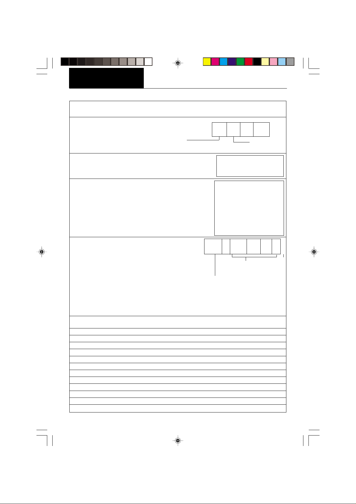
All communication is accomplished using standard ASCII format. Only the characters shown
in the following table are acknowledged by the
balance. Any other commands, control characters or spaces are ignored. Commands sent
to the balance must be terminated with a
carriage return (CR) or carriage return-line line
feed (CRLF). For example, a tare command
should appear as shown in the adjacent diagram. Data output by the balance is always
terminated with a carriage return - line feed
(CRLF).
TARE *
PRINT *
1 5 V dc (5 mA max.)
2 Data Out (TXD)
3 Data In (RXD)
4* Tare (External signal)
5 Clear To Send (CTS)
6 Data Terminal Ready (DTR)
7 Ground
8 Request To Send (RTS)
9* Print (External signal)
* External PRINT and/or TARE
switches may be installed as
shown in the diagram. Momentary
contact switches must be used.
TARE COMMAND
Field: T CR LF
Length: 1 1 1
5
Page 12
INSTALLATION
Menu
Menu
Command
Character Description
RS232 COMMAND TABLE
? Print current unit.
Grams, Dwt, Carat, Oz Av, Oz t, Grain, Tael 1,
Tael 2, Tael 3, Momme, Custom Unit
xI Set averaging level to “x”, where x = 0, 1, 2
xM Places balance in mode “x”, where x = 1 to 11
(see table).
If unit is not already enabled,
command will be ignored.
P Print display data
When “numeric only” displaydata is
selected for output in the RS232 menu,
the Mode field is not output.
hhmmss TIME Set current time to “hh: mm: ss”, hh is between 0 - 23.
TIME Print current time.
mmddyy DATE Set current date “mmddyy”.
DATE Print current date.
% Print current % ref.
# Print current ref., any function.
AC Abort calibration /Test.
C Start an auto calibration.
E Go to initial state of current function.
F Print current function.
M Same as mode button.
xD Set 1 second print delay (set x = 0 for OFF, or x = 1 for ON).
ID Print current ID string.
xxxxID Enter ID string (xxxx limit to 8 characters).
Field: Mode Stab CR LF
Length: 5 1 1 1
0 = minimum level
1=
2 = maximum level
1 = grams
2 = pennyweight
3 = carats
4 = avoidupois ounces
5 = troy ounces
6 = grains
7 = taels
8 = mommes
11 = custom unit
Field: Weight Mode Stab CR LF
Length: 10 1 5 1 1 1
Displayed weight sent right justified
w/lead zero blanking.
Nine characters include:
decimal point (1)
weight (7 max))
polarity (1): blank if positive
6
blank if stable
“ ? ” if unstable
Same as ?
command
“ - ” if negative
Page 13
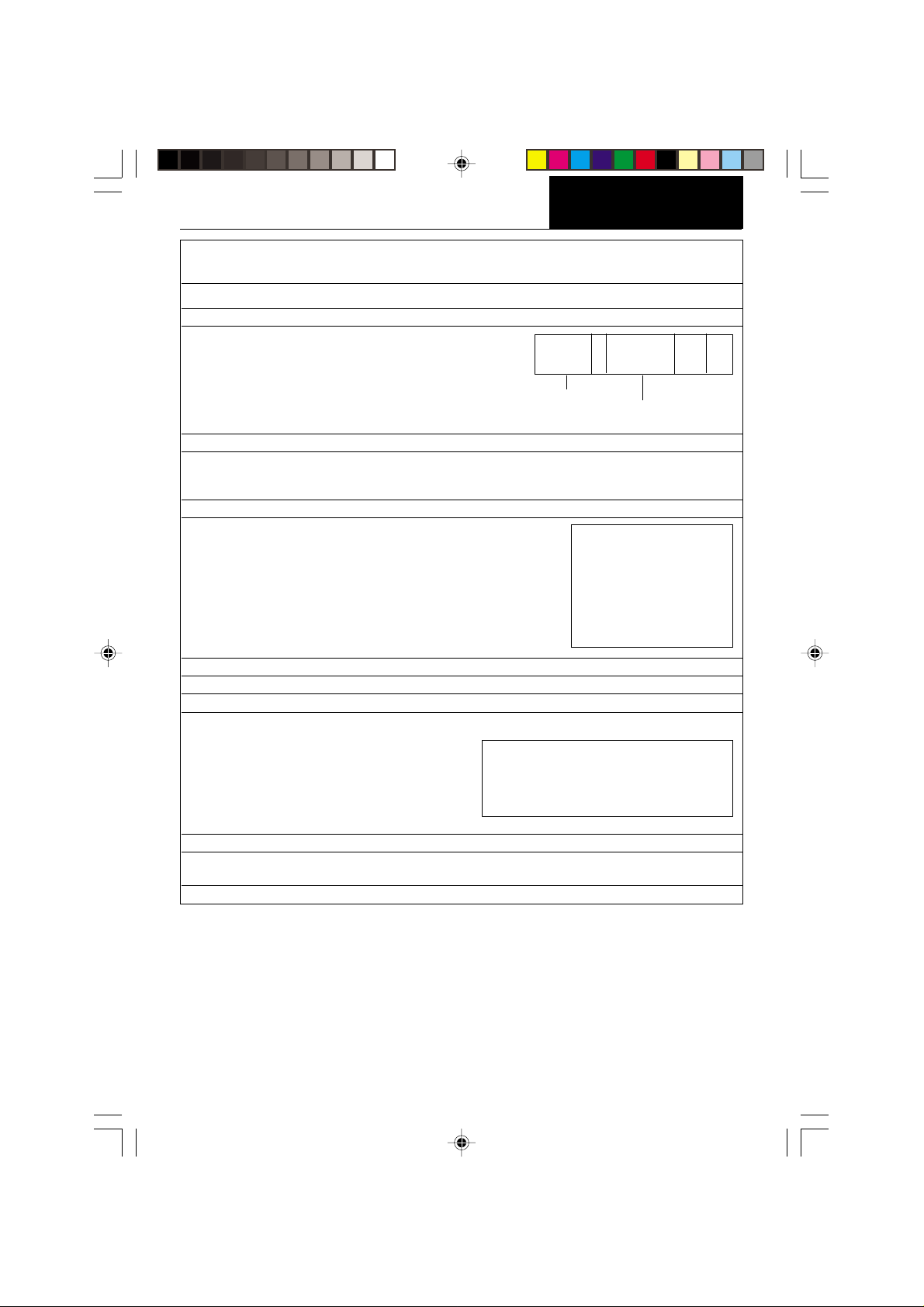
Command
Menu
Menu
Character Description
xS Set stable data only printing (set x = 0 for OFF, or x = 1 for ON.
T Same effect as pressing on tare button.
V Print EPROM version
Field: Model # 1 EPROM # CR LF
Length: 6 16 1 1
INSTALLATION
Balance Model
x# Set current ref., any function, CW takes two reference separated by a space.
x% Doanloads reference weight “x” for percent mode. “x” must be in grams. Command is
ignored if percent mode is disabled. If percent mode is enabled, balance will automatically
switch to percent mode display.
xF Set current function to “x”. x = 0 to 6. Setup menu must be unlocked.
xZ Set Auto Zero to “x”. x = 0 for OFF, x = 1 for ON
xSL Set stability level. User menu must be unlocked. x = 0 to 3
Z Zero request (Gross tare) if Net/Gross enabled.
nnnA Set Auto Print feature to “nnn” (see table).
nnn = 0 Turns feature OFF
nnn = S Output on stability
nnn = C Output is continuous
nnn = 1-256 Sets Auto Print interval
Esc L Prints listing of Setup and Print menu settings.
Esc R Resets Setup and Print menus to factory defaults.
CAUTION: This will reset RS232 configuration.
Esc S Save current settings.
“98101-xx Sr#x.xx”
0 = None
1 = Percent
2 = Parts Counting
3 = Check Weighing
4 = Animal Weighing
5 = Fill Guide
6 = High Point
7
Page 14
INSTALLATION
Menu
Menu
Connecting Power
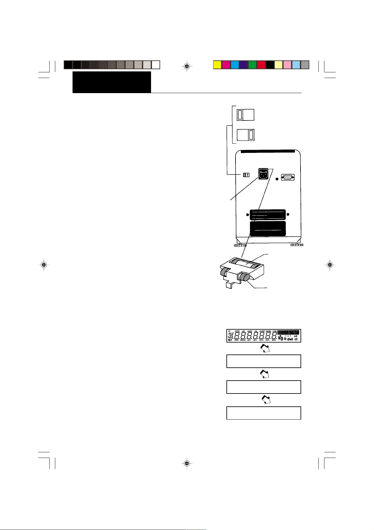
1. Before connecting the power cord, check
that the line voltage switch located at the
rear of the balance is set correctly for your
location. If not, use a small screwdriver to
set the switch correctly.
2. Make sure the doors to the weighing chamber are closed.
2. Connect the power cord receptacle to the
plug on the rear of the balance.
3. Plug the power cord only into a convenient
grounded AC outlet. The balance signals
one long beep to indicate power has been
applied.
Spare Fuse
A spare fuse is provided in the fuse holder as
shown in the diagram. All models use a
T 160 mA/250 V fuse.
Power
Connection
Fuse Holder
115V
230V
Line
Voltage
Switch
For 100-120 V∼
For 220 240 V∼
Active Fuse
Spare Fuse
Self Test
When power is applied to the balance, it begins
a self test cycle. During this time, the display
cycles as shown.
NOTE: Sr shown in the display is the software
revision and may be different in your balance.
After the self test is completed, the display turns
off. Allow the balance to stabilize for about 2
hours before using it.
s R 3.1
c h e c · ·
8
Page 15
OPERATION
Menu
Menu
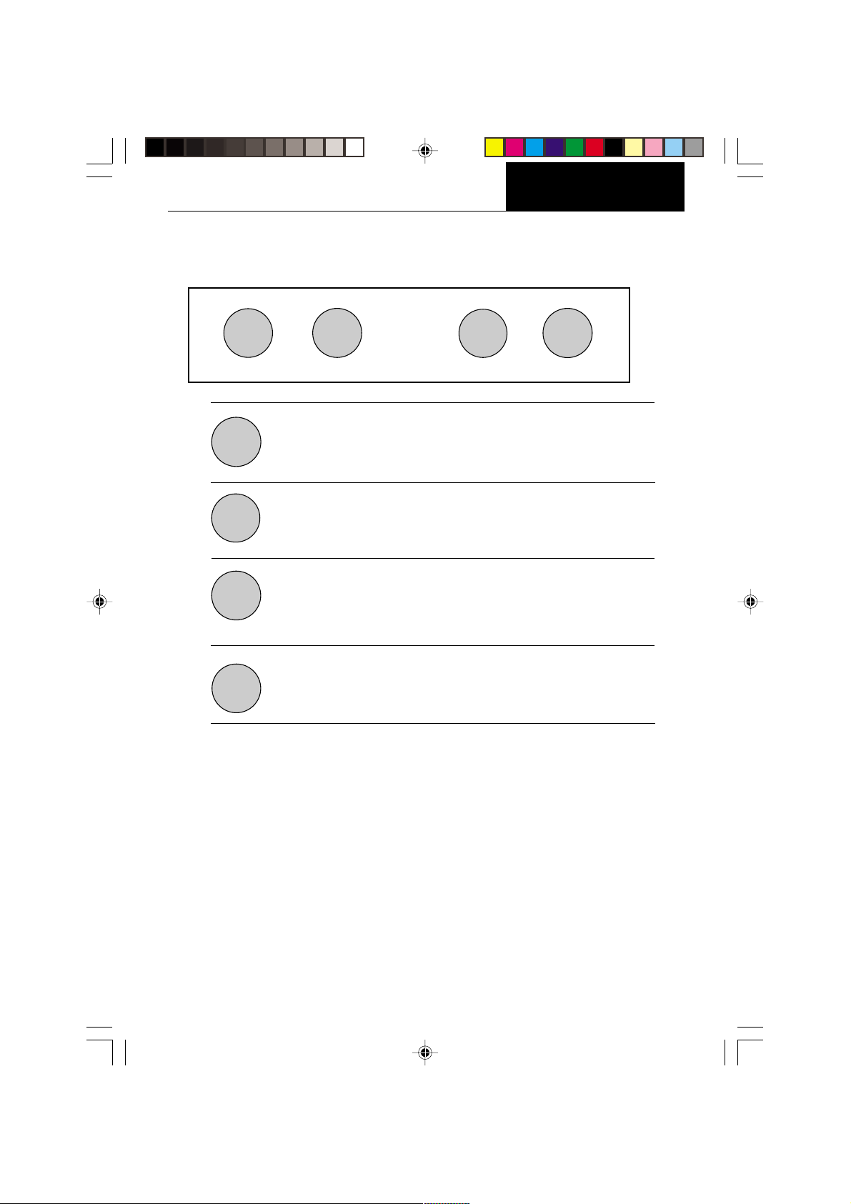
Switch Functions
OPERATION
PRINT
ON
TARE
OFF
MODE
PRINT
MODE
Press and Release:
Turns on the balance if it is off, zeros the balance. In the menu
system, this button is used to accept a choice or enter a submenu.
Press and Release:
Turns the balance off.
Press and Release:
Selects weighing units functions or options. In menus, changes to
next step or value.
Press and Release:
Sends weight data, statistical data, GLP data to computer/printer. In
menus, allows returning to a previous menu step.
OFF
ON
TARE
Before using the balance, carefully review the Symbols Used for Operation of the Balance
shown on page 10, Navigating the Menus on page 11and Operational Guide/Index on page
12.
Please read the entire manual as there are many features which can be enabled. The
balance is shipped from the factory ready to operate with default settings as shown in the
menus.
The balance is a high precision instrument and will give you years of service if kept clean
and handled carefully. If you have any problems operating the instrument or require
additional information, please feel free to contact our Customer Service Department at
(800) 526-0659.
9
Page 16
OPERATION
Menu
Menu
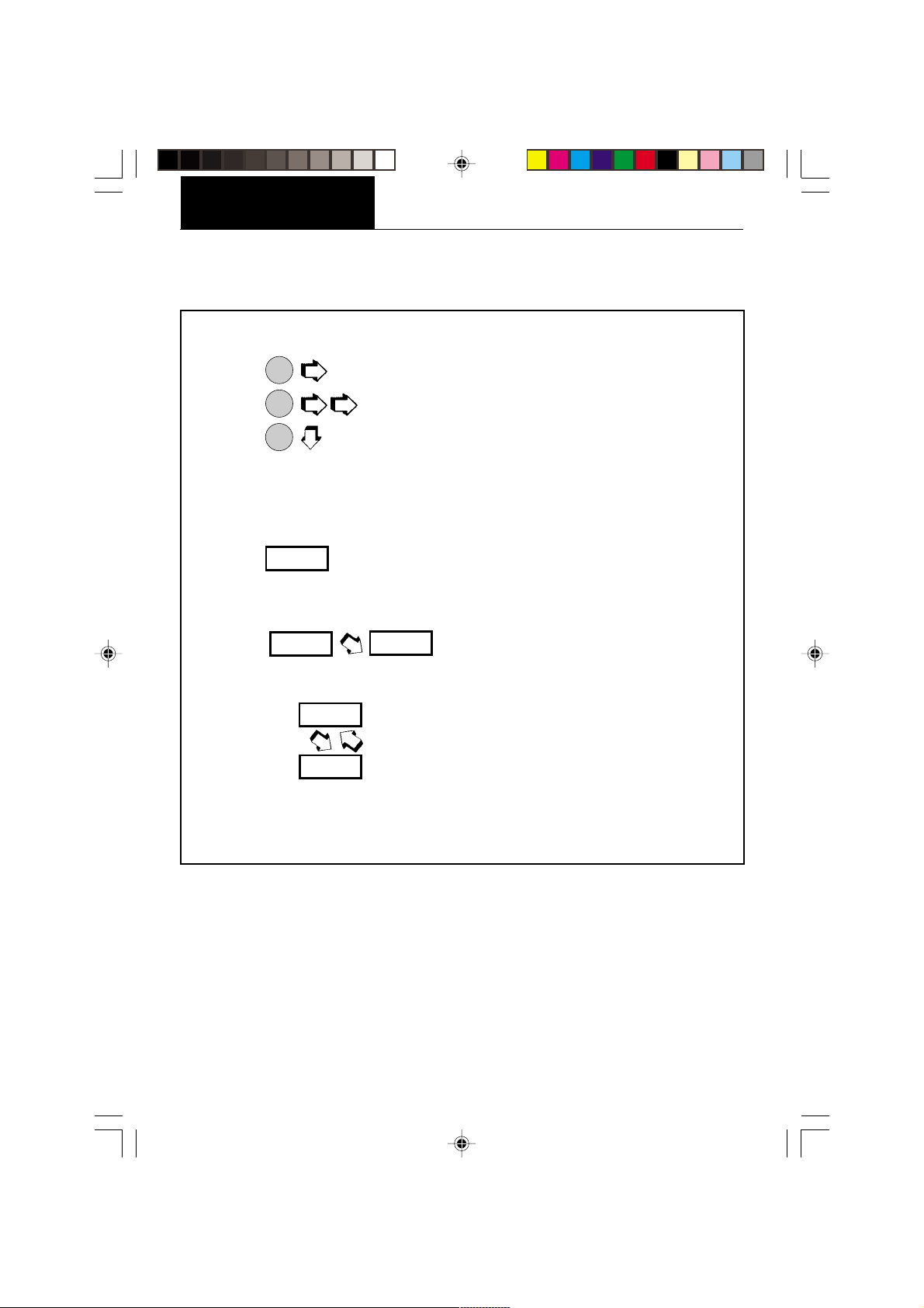
Symbols Used for Operation of the Balance
This instruction manual uses certain symbols to explain various operational procedures and
actions that occur. Examples of the symbols used are shown as follows:
Pushbutton Switches:
ON
= NORMAL PRESS AND RELEASE
TARE
ON
= MULTIPLE PRESS
TARE
ON
Display Area:
= PRESS AND HOLD FOR DESIRED DISPLAY
TARE
DISPLAY AREA - AS A RESULT OF USER ACTION
DISPLAY AREA - AUTO CHANGE OCCURS
DISPLAY AREA -SWITCHES BACK AND FORTH
10
Page 17
OPERATION
Menu
Menu
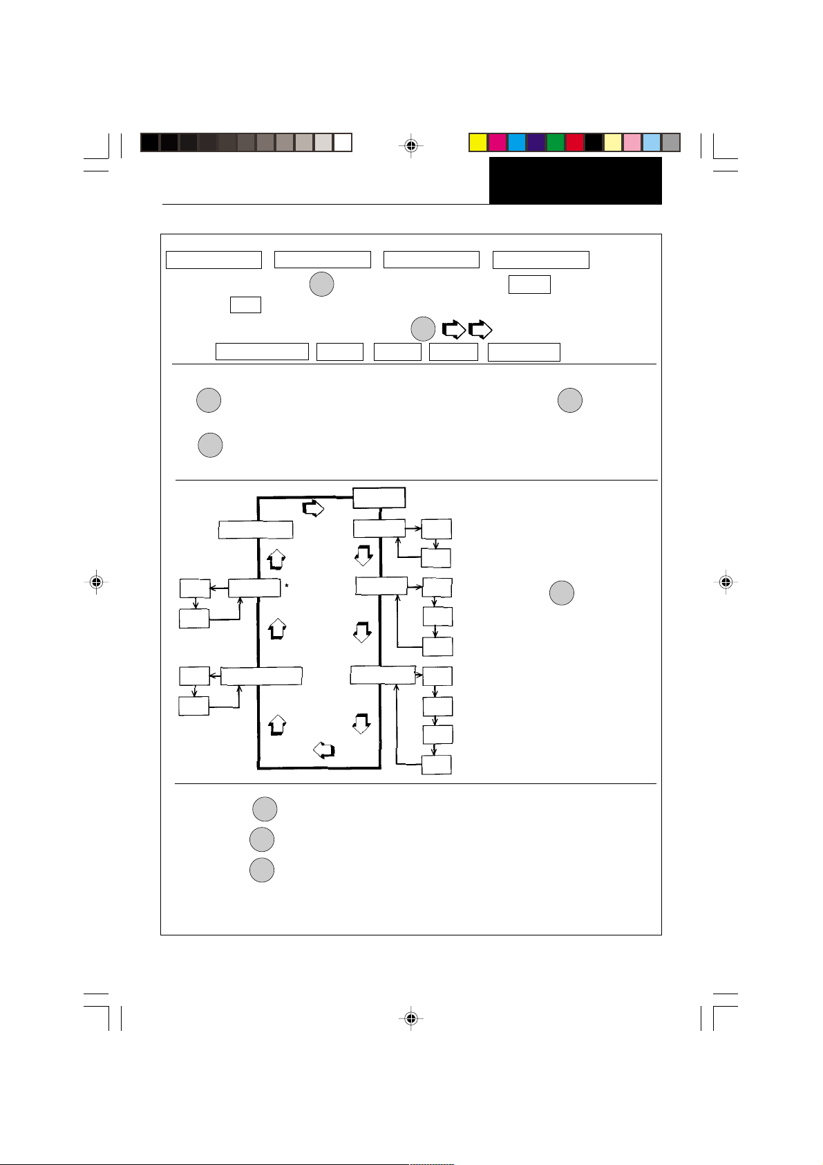
Navigating the Menus
There are four menus used in the balance:
CALIBRATION USER SETUP PRINT
To enter the menus, the
released, CAL is displayed which is the Calibration menu.
When in the menus, repeated pressing of
menus. CALIBRATION USER SETUP PRINT END
Each menu contains selections (submenus) which can be set for specific operations.
MODE
The
button is used to advance though the submenu selections. The
or accepts the submenu selection and returns to the beginning of the submenu selection.
PRINT
The
button is used to backup in the submenu if a change is desired.
The following sample illustrates the USER menu and submenu items
ON
button is pressed and held until MENU is displayed. When
TARE
MODE
advances through the
MENU
ON
button enters
TARE
END USER
ON
DUAL
OFF
AUTO ZERO
ON
OFF
RULES: Use
Use
Use
After selections are made, always exit menus through END
store settings.
USER
RESET
YES
NO
AL
STABILTY
MODE
button to advance.
ON
button to enter or accept submenu.
TARE
PRINT
button to backup.
NOTE:
Each menu is constructed
in the form of a loop.
Advancing from one
submenu item to the next
0
1
by using the
will eventually return to
the beginning of the menu
2
* Only on AP250D Models.
0
1
2
3
MODE
button
to
MENU
11
Page 18
OPERATION
Menu
Menu
Operational Guide/Index
The Operational Guide/Index lists the pages for all balance operations and options. After
settings are made, exit menus to save settings.
FUNCTION TO OPERATE SETUP
(See pages) (See pages)
1. Turning the Balance ON 13 ----
2. Weighing (grams) 14 ----
3. Taring 14 ----
4. Percent Weighing 15 38
5. Parts Counting 16 38, 43
6. Check weighing 17 38, 43
7. Animal Weighing 18 38, 46
8. Fill Guide 19 38, 46
9. High Point 20 38
10. Printing Data 21 to 26 50, 51, 55 to 59
11. List 22 50, 59
12. Menu Lockout 28 ----
13. Calibration 29 to 31 ----
14. Net/Gross Weighing ---- 40
15. Custom Units ---- 40
16. GLP ---- 42, 54
17. Time ---- 47, 48
18. Date ---- 49
19. Lockswitch ---- 50
20. Legal for Trade ---- 35, 37
21. Changing Units ---- 37
22. Statistics ---- 39
23. Averaging Level ---- 32, 33
24. Stability ---- 32, 33
25. Auto Zero ---- 32, 34
26. Dual Range (AP250D) ---- 32, 34
27. Reset User ---- 32
28. Reset Setup ---- 36
29. Reset Print ---- 52
30. Communications ---- 52 to 54
12
Page 19
OPERATION
Menu
Menu
Turning the Balance ON
1. After the Self Test in the Installation Section is completed (power applied to the
balance), make sure the pan on the balance is clear, then, close the chamber doors.
ON
TARE
ap25FD
sR3.1
2.
˛
0.00000
s
g
g
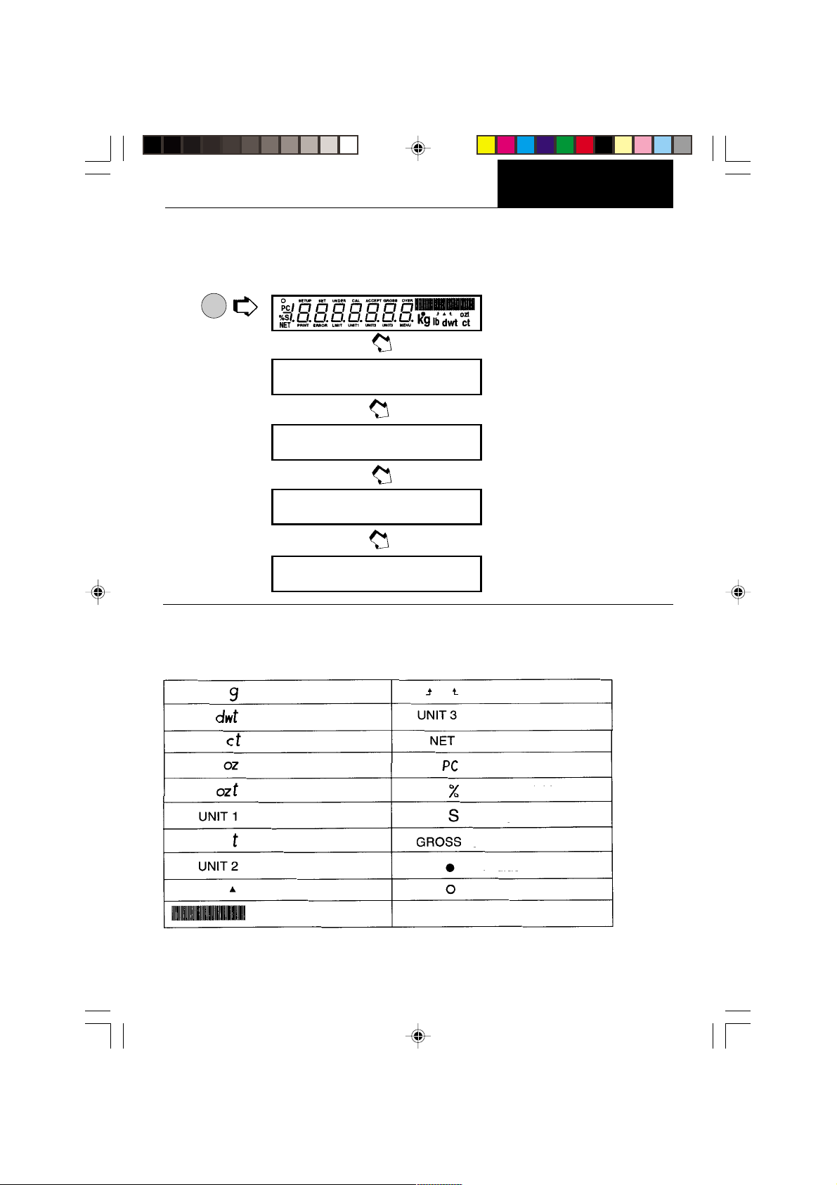
Display Indications
The following table describes each of the display indicators.
DISPLAY INDICATORS
grams check weighing limits
pennyweight custom unit/volume
carats net indicator
ounces parts counting
troy ounces percent weighing
grains stability indicator
taels gross (total) indicator
mommes fill guide
user calibration indicator center of zero
I
capacity guide
13
Page 20
OPERATION
Menu
Menu
Stabilization
Before initally using the balance, allow time for it to adjust to its new environment. The
balance only requires to be plugged in to warm up. Recommended warm up period is twenty
(20) minutes. The balance is powered whenever it is plugged into a power source.
Auto Range (AP250D and E Only)
Modes AP250D and E offer both a fine range (0.01 mg readability from 0 to 52 g) and a coarse
range (0.1 mg over 52 g). When first turned on, the balance is in the fine range. It remains
in this range until the weight on the pan exceeds 52 g. When weight on the pan is greater
than 52 g, the balance switches to the coarse range.
If weight on the pan falls below 52 g, it automatically switches back to the fine range.
Weighing
ON
1.
to rezero the display.
TARE
2. Place the object(s) or material to be weighed on the pan.
3. Wait for the stability indicator to appear before reading the weight.
STABILITY INDICATOR
200.0000
s
IIIIIIIIIIIIIIIIIIIIIIIIIIIIIIIIIIIIIIII I
g
NOTE: The capacity guide (bars) indicates the percentage of the current weight to the
balance capacity. The example above illustrates a 200 gram weight, (balance full capacity
210 grams).
CAPACITY GUIDE
Taring
When weighing material or objects that must be held in a container, taring stores the
container weight in the balance’s memory, separate from the weight of the material in the
container.
1. Place an empty container on the pan. Its weight is displayed.
ON
2.
3. Add material to the container. As material is added, its net weight is displayed.
4. Removing the container and material from the pan will cause the balance to display the
5.
, the display blanks until stable weight readings are received, then indicates
TARE
zero. The container’s weight is stored in memory.
container’s weight as a negative number.
ON
resets the balance to zero.
TARE
14
Page 21
Percent Weighing
Menu
Menu
OPERATION
Percent Weighing is
Percent Function is selected under the Setup
menu. Refer to page 38. Percent weighing
permits you to place a reference load on the
balance, then view other loads as a percentage of the reference. The load you place on the
platform as a reference may be displayed as
any percentage you select from 5% to 100%
enabled only
when the
EXAMPLE
A 10g reference load is set for 20%:
• A subsequent load of 100 g will be
displayed as 200%.
• A subsequent load of 200 g will be
displayed as 400%.
(in 1% increments). One hundred percent does
not necessarily have to represent the reference load. Subsequent loads, displayed as a
percentage of the reference are limited only by the capacity of the balance. The default
setting is Reference 100%.
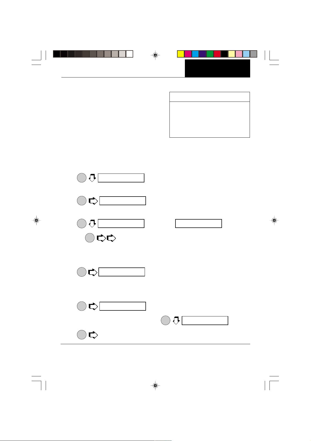
To perform percent weighing when in a weighing mode, use the following procedure:
ON
1.
TARE
pCT cON
.
%
IIIIIIIIIIIIIIIIIIIIIIIIIIIIIIIIIIIIIIII I
2. Place an empty container on the pan (if one will be used).
ON
3.
. This is the current reference percentage.
TARE
seT 100
%
IIIIIIIIIIIIIIIIIIIIIIIIIIIIIIIIIIIIIIII I
NOTE: The reference percentage can be changed to any value from 5 to 100.
MODE
4.
NOTE:
seT 5
increments to .
%
PRINT
does not return to a lower number. Instead, it sends Set x%
IIIIIIIIIIIIIIIIIIIIIIIIIIIIIIIIIIIIIIII I
seT 100
%
IIIIIIIIIIIIIIIIIIIIIIIIIIIIIIIIIIIIIIII I
command through the RS232 Interface, where x = 5 to 100.
5. When the selected reference value appears on the display, place the reference load
in the container (or directly on the pan if no container is used).
ON
8.
, display indicates the reference load as the percent-
TARE
100.0
%s
IIIIIIIIIIIIIIIIIIIIIIIIIIIIII II I
age entered. The bar graph indicates the load relative to the capacity of the balance.
9. Remove the reference load from the balance and replace it with another load. The
second load is displayed as a percentage of the reference.
10.
MODE
to view alternate display in units.
100.0000
%s
11.To restart percent weighing at any time,
ON
12.
to exit to a weighing mode.
TARE
IIIIIIIIIIIIIIIIIIIIIIIIIIII I
g
ON
TARE
pCT cON
.
%
IIIIIIIIIIIIIIIIIIIIIIIIIIIIIIIIIIIIIIII I
15
Page 22
OPERATION
Menu
Menu
Parts Counting
Parts Counting is
menu. Refer to page 38. In the parts counting mode, the balance displays the quantity of
parts you place on the pan. Since the balance determines the quantity based on the average
weight of a single part, all parts must be reasonably uniform in weight. The accuracy of parts
counting results is determined by the error level entered in PC Err of the Setup Options
submenu. Refer to page 43. The default setting for PC Err is off.
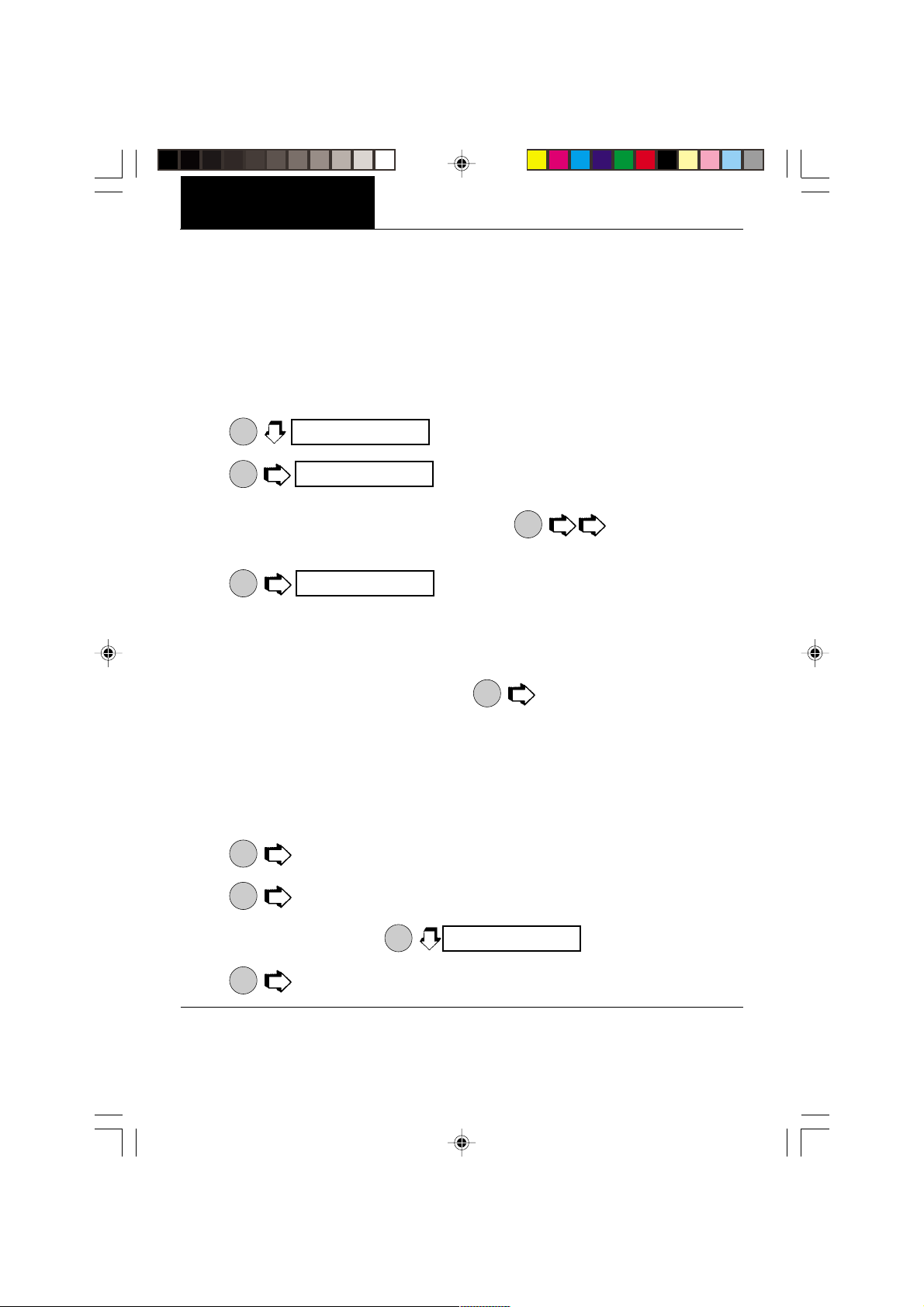
To perform parts counting when in a weighing mode, use the following procedure:
enabled only
when the Parts Counting Function is selected in the Setup
ON
1.
TARE
ON
2.
TARE
PC
.
. The balance requires a sample of the parts to use
pc cON
PC
aDD 5
IIIIIIIIIIIIIIIIIIIIIIIIIIIIIIIIIIIIIIII I
IIIIIIIIIIIIIIIIIIIIIIIIIIIIIIIIIIIIIIII I
as a reference for counting. The default for the sample size is 5 parts, but this can be
changed to 10, 20, 30, 40, 50, or 100 parts by
MODE
(Larger samples yield
more accurate results). Add the required number of sample pieces to the pan.
ON
3.
TARE
PC
(indicates 5 pieces).
5
5
IIIIIIIIIIIIIIIIIIIIIIIIIIIIIIIIIIIIIIII I
4. If Add X is displayed, the sample is too small to provide results within the selected error
level (PC Error of the Setup Options submenu).
NOTE:X represents the number of additional parts needed to provide a sufficient sample.
5. Add the required number of parts, then
ON
again.
TARE
6. To count additional pieces, add them to the pan. The display indicates the actual
number of pieces based on their sample size. Tolerance will be within whatever was
selected under the Parts Counting Error Level.
NOTE:If the balance controls are not touched, the sample size is stored in memory. You
can continue to use the balance to measure quantities as long as the samples to be
measured are of the same weight.
MODE
7.
to display the weight of the pieces on the pan.
MODE
8.
again to display the number of pieces.
9. To restart parts counting,
MODE
10.
, the balance returns to a weighing mode.
ON
TARE
PC
pc cON
.
16
IIIIIIIIIIIIIIIIIIIIIIIIIIIIIIIIIIIIIIII I
Page 23
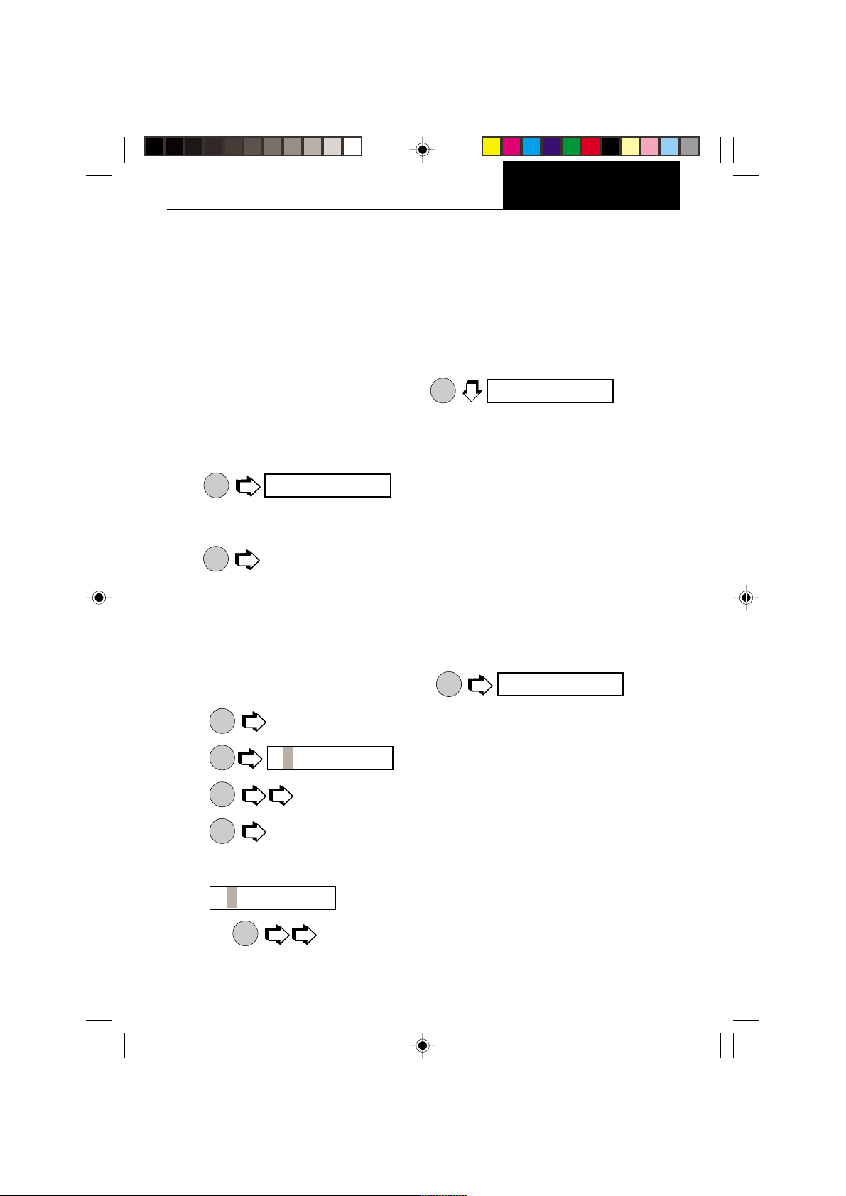
Check Weighing
Menu
Menu
OPERATION
Check Weighing is
enabled only
when the Check Weighing Function is selected in the
Setup menu. Refer to page 38. Refer to page 43, Check Weighing Options under the Setup
menu to set the Reference Type and Display Type options. In the check weighing mode, a
reference weight can be set into the balance either as a reference weight on the pan or as
a user entered number. The balance display shows either under, accept or over as each
sample is weighed.
If reference weight was selected under CW Options submenu:
1. With the balance in the weighing mode,
ON
.
TARE
seT Ref
IIIIIIIIIIIIIIIIIIIIIIIIIIIIIIIIIIIIIIII I
NOTE:If reference number was selected, go to step 7.
2. Place a sample weight on the pan which is considered to be the under limit for check
weighing.
ON
3.
.
TARE
seT Ref
IIIIIIIIIIIIIIIIIIIIIIIIIIIIIIIIIIIIIIII I
4. Place a sample weight on the pan which is considered to be the over weight limit for
check weighing.
ON
. The display blanks until a stable reading is achieved, then it goes to either
5.
TARE
the (Normal, None or Sign) display type previously selected in CW Options submenu
to indicate under, over or acceptacle limits of the objects being weighed.
6. Check weighing can now be made by removing a sample and placing a new sample
on the pan.
If reference number was selected under the CW Options submenu:
7. With the balance in the weighing mode,
ON
.
TARE
seT Ref
IIIIIIIIIIIIIIIIIIIIIIIIIIIIIIIIIIIIIIII I
MODE
8.
9.
10.
11.
to return to weighing.
ON
TARE
MODE
until the first digit (under weight) is correctly displayed.
ON
to accept the value.
TARE
UNDER
000.0000
indicates under value with first digit flashing.
g
12.Repeat steps 10 and 11and set all digits to the desired value. When the last digit is
entered, display changes to an over value to be entered with the first digit flashing
000.0000
NOTE:
PRINT
OVER
.
g
allows going back.
17
Page 24
OPERATION
Menu
Menu
Check Weighing (Cont.)
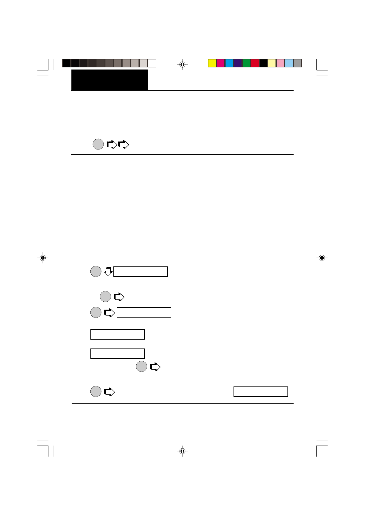
13. Repeat steps 10 and 11 to set the over value. When the last digit is entered, the display
indicates one of three display modes for check weighing.
14.Check weighing can now be performed by removing a sample and placing a new
sample on the platform.
MODE
15.
Animal Weighing
allows other weighing units to be displayed if previously selected.
Animal Weighing is
enabled only
when Animal Weighing Function is selected under the
Setup menu. Refer to page 38. To set options, refer to page 46, Animal Weighing Options
under the Setup Options submenu. Under normal weighing conditions, the movement of
animal subjects on the balance platform causes unstable fluctuating display readings and
corresponding inaccuracies in the weighing result. The Animal Weighing mode is a feature
designed to minimize these fluctuations through a combination of several digital signal
processing techniques.
When used in this mode, the balance automatically detects the presence of a subject placed
on the platform and starts an animal weighing cycle. The balance samples the weight data
for a variable sampling interval and processes the data to filter out the instabilities by the live
animal.
With the balance in a weighing mode, proceed as follows:
ON
1.
TARE
a_ıcON
(Animal Weighing Container).
IIIIIIIIIIIIIIIIIIIIIIIIIIIIIIIIIIIIIIII I
2. Place the container on the platform.
MODE
NOTE:
3.
TARE
to return to weighing mode.
ON
. The container weight is tared.
ReaDy
IIIIIIIIIIIIIIIIIIIIIIIIIIIIIIIIIIIIIIII I
4. Place the subject in the container. The balance indicates a countdown to
a_ı 0
IIIIIIIIIIIIIIIIIIIIIIIIIIIIIIIIIIIIIIII I
. This cycle accommodates for movement. The balance then
displays the actual weight of the subject with flashing unit indicator and returns to
ReaDy
another subject or
IIIIIIIIIIIIIIIIIIIIIIIIIIIIIIIIIIIIIIII I
ON
TARE
after approximately six seconds. Repeat steps 1 through 4 for
to start another weighing cycle.
NOTE:If Auto Print is enabled, the display returns to ready in approximately one second.
MODE
5.
to return to weighing mode while display shows .
ReaDy
IIIIIIIIIIIIIIIIIIIIIIIIIIIIIIIIIIIIIIII I
18
Page 25
OPERATION
Menu
Menu
Fill Guide
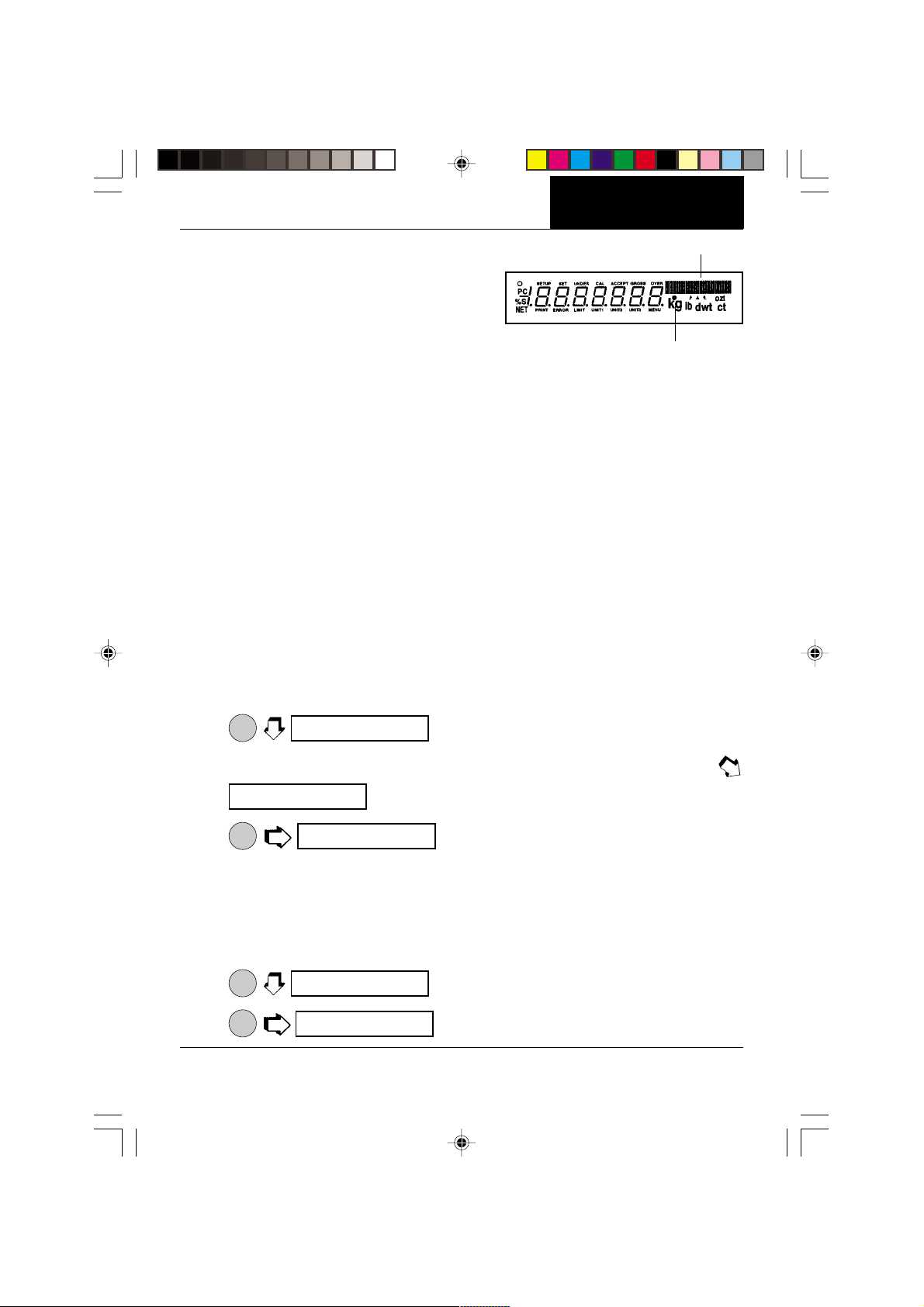
Fill Guide is
enabled only
when Fill Guide
FILLGUIDETM BAR GRAPH
Function is selected under the Setup menu.
Refer to page 38. To set options, refer to page
46, Fill Options under the Setup Options
submenu.
FILLGUIDE
TM
INDICATOR
The FillGuideTM is a bar graph which appears in the upper right hand portion of the display.
When the load on the balance is at the balance's capacity, all of the segments are on. When
the load is at half capacity, only the first half of the segments are on. During normal operation
of the balance, the bar graph displays the relationship between the load on the pan and the
capacity of the balance. In the Fill Guide mode, the bar graph can be set to a desired target
value. The FillGuide
TM
feature can be used in any one of the available weighing units.
The Fill Option under the Setup Options submenu provides two choices for a reference
weight (similar to check weighing). Either a mass can be placed on the pan and used as a
reference weight or a number can be entered to establish the weight value. Both methods
are used to establish a reference for a 100% bar graph reading. Target parameter provides
two choices, one is fill to the reference, the other to zero weight and Target = to reference..
With the balance in a weighing mode, proceed as follows:
Reference Weight
With the balance in a weighing mode, and if reference weight was selected under Fill Options
submenu proceed as follows:
ON
1.
.
TARE
seT Ref
IIIIIIIIIIIIIIIIIIIIIIIIIIIIIIIIIIIII I
2. Place a sample weight on the pan which is the reference weight
IIIIIIIIIIIIIIIIIIIIIIIIIIIIIIIIIIII I
s
. Assumes 50 grams weight reference.
50.00
IIIIIIIIIIIIIIIIIIIIIIIIIIIIIIIIIIIII I
•
g
3.
seT Ref
ON
. The display indicates a 50 gram mass (target =
TARE
reference. For target = to zero, display shows 0.0000 as the actual weight of the sample
with the bar graph at 100%.
4. The Fill Guide feature can now used by placing samples on the pan. If the sample is
equal to the reference weight used to calibrate the fill mode, the actual weight is
displayed with a full bar graph. When target is selected, the balance will show the
normal weight of the object on the pan.
ON
5.
6.
to exit the fill option mode.
TARE
MODE
, the balance is now in a weighing mode.
seT Ref
0.00000
s
IIIIIIIIIIIIIIIIIIIIIIIIIIIIIIIIIIIII I
IIIIIIIIIIIIIIIIIIIIIIIIIIIIIIIIIIIII I
g
19
Page 26
OPERATION
Menu
Menu
Fill Guide (Cont.)
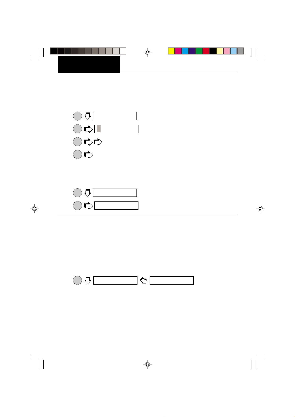
Reference Number
If reference number was selected under the Fill Option submenu with the balance in a
weighing mode, proceed as follows:
ON
1.
2.
3.
4.
.
TARE
ON
. Set the flashing digit to the desired weight value.
TARE
MODE
until the first digit is correctly displayed.
ON
to accept the digit.
TARE
seT Ref
00000.00
IIIIIIIIIIIIIIIIIIIIIIIIIIIIIIIIIIIIII I
g
5. Repeat steps 3 and 4 until all digits are set. When the last digit is entered , the balance
is automatically in the fill mode.
6. The fill mode can now be used by placing samples on the pan. If the sample weight
equals the reference weight, the bar graph indicates 100%, the weight is displayed.
ON
7.
8.
to exit the fill option mode.
TARE
MODE
, the balance is now in a weighing mode.
seT Ref
0.00000
s
IIIIIIIIIIIIIIIIIIIIIIIIIIIIIIIIIIIIII I
IIIIIIIIIIIIIIIIIIIIIIIIIIIIIIIIIIIII I
g
High Point
High Point is
Refer to page 38. High point is a feature which permits a number of samples to be weighed
with the balance
samples which are in between the low and high points are disregarded and not displayed.
NOTE: When using this function, the balance does not respond to weights below 100 digits.
enabled only
when High Point Function is selected under the Setup menu.
storing the lowest
sample weight and the
highest sample weight
. The
With the balance in a weighing mode, proceed as follows:
ON
1.
, LIMIT is dis played,
TARE
hi pT
s
LIMIT
0.00
IIIIIIIIIIIIIIIIIIIIIIIIIIIIIIIIIIIII I
g
indicating the function is on.
2. Place the first sample on the balance pan. When the balance has stabilized, the weight
is displayed. Remove the weight.
3. Place a second sample on the pan. After the balance stabilizes, the second sample
weight is displayed if it is greater than the first sample. This procedure can be continued
with a number of samples. The highest weight sample is always displayed.
20
Page 27
High Point (Cont.)
Menu
Menu
ON
4.
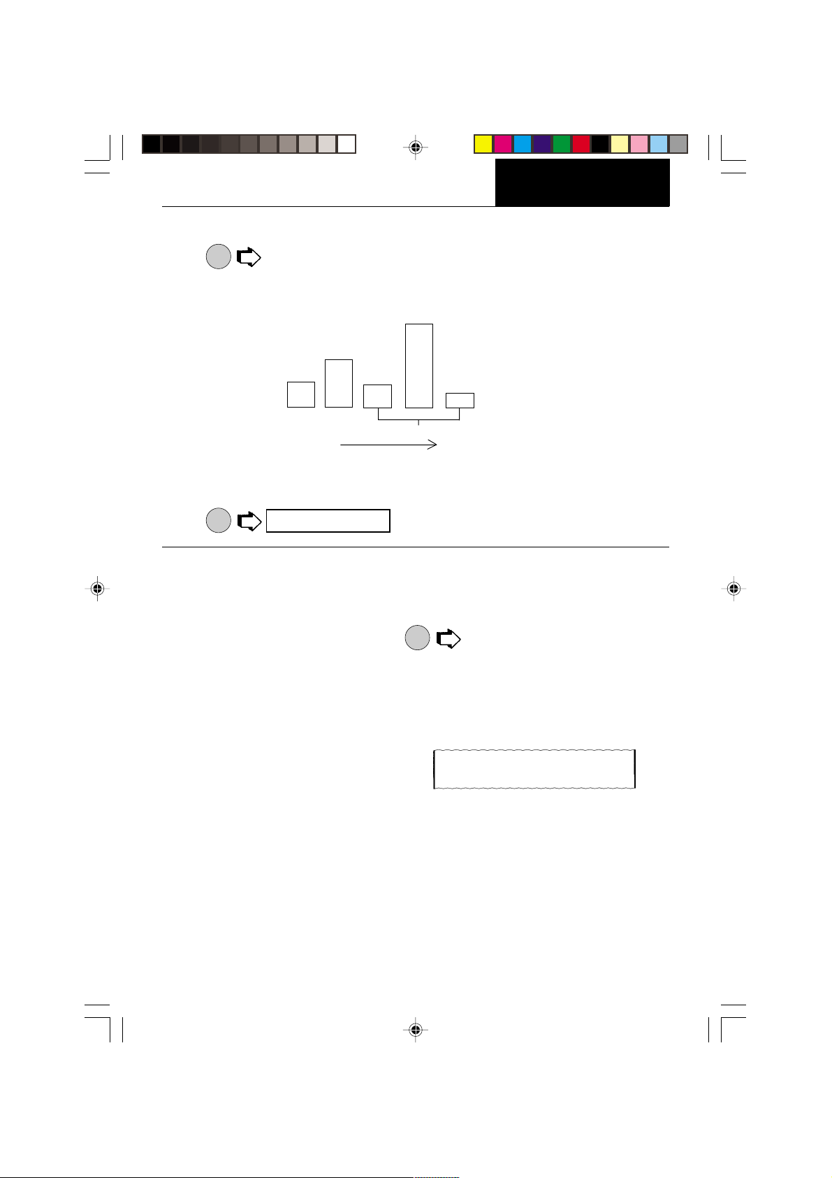
To view the lowest and highest sample weight. The display LIMIT flashes,
TARE
the lowest sample weight is displayed followed by two short beeps, the display then
indicates the highest sample weight for a few seconds then automatically changes
back to the normal weighing mode.
40g
20g
5g
ORDER SAMPLES TAKEN IN
5. To use the High Point function again, repeat steps 1 through 4.
4g
NOT DISPLAYED
2g
OPERATION
MODE
6.
to exit High Point and return to a weighing mode.
0.00000
s
g
Printing Data
Printing data to an external computer or printer requires that the communications parameters in the Print menu be set first. Refer to page 51 Print menu. A wide variety of printing
options are available, refer to page 55, Print Options under the Print menu and set the desired
options before proceeding. To print data,
This section defines the various printing setups with printing samples.
Time and Date
When time and date are entered in the
balance through the Setup menu and with
both Time and Date options set to ON
under the Print Options submenu, each
printout starts with the time and date on
the first line.
PRINT
.
6/22/95 1:00:30 PM
21
Page 28
OPERATION
Menu
Menu
Printing Data (Cont.)
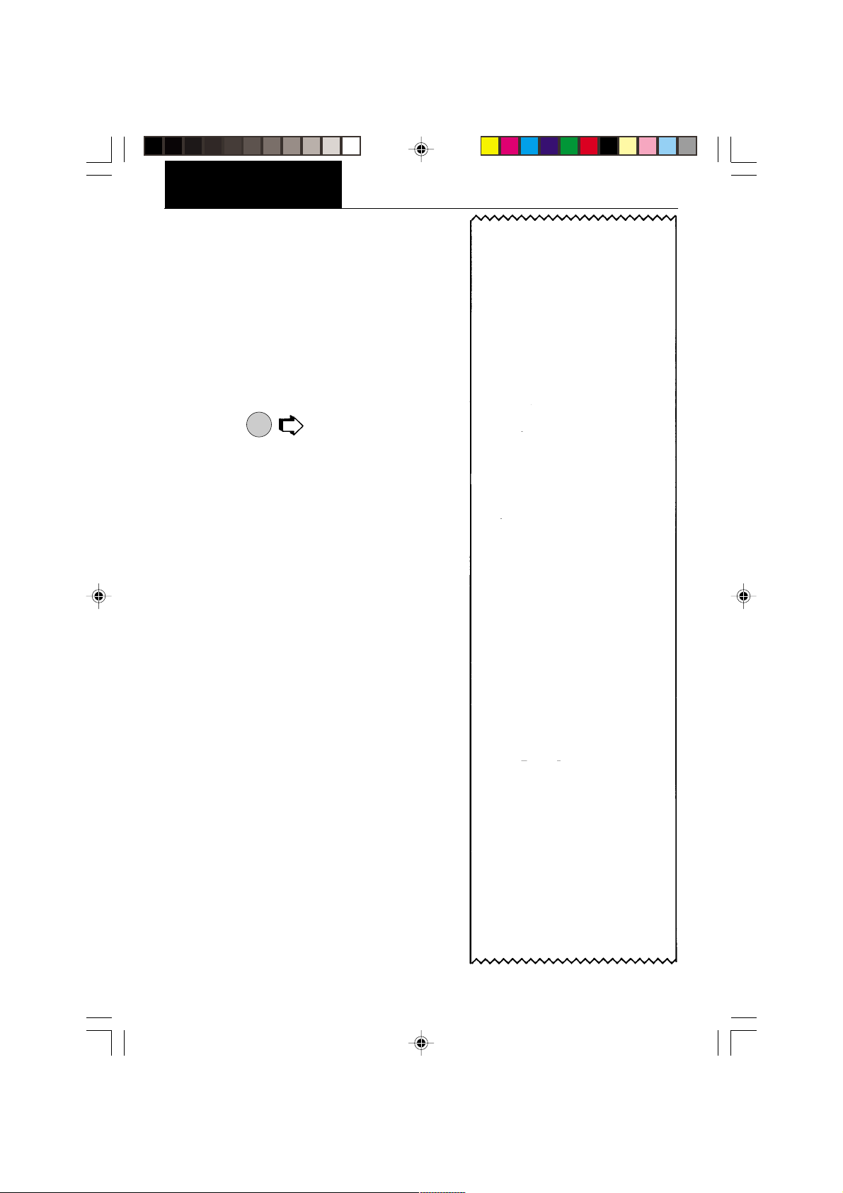
List
List is a convienent method of examining which
parameters are set up in the balance. The parameters do not show up on the display but print
out when selected. Both the Setup and Print
menus have a List function.
When LIST is displayed in either the Setup or
ON
Print Menu,
of the User, Setup and Print menus to be printed
on an external printer or computer screen.
The sample shown, indicates the status in three
menus.
causes the parameters
TARE
AP250D 98101-35 Sr# 3.0
183
User Menu
AL = 1, Stb = 1
AZT = On
Setup Menu
LFT is Off
Enabled Modes:
g, dwt,
ct, oz,
oz t, GN
custom
Tael = Hong Kong
Function = Animal Weighing
AW Lev = 1
Statistics On
Std Dev = Pop
Mean = On
Sum = On
Max = On
Min = On
Diff = On
Net = On
GLP
Time/Date On
Bal Id = On
User Id = On
Project # = On
Cal = On
Name = On
Time = US 8:24:06 AM
Date = US 6/22/95
Lock Switch is Off
22
Print Menu
RS-232 = 2400: N: 7: 2
Print Options
Auto Print = Off
Interval = 6
Non - PL = 100.0000g
Non - PH = 200.0000g
Stable Print = Off
Nu = Off
Time = On
Date = On
Print Ref = On
Print Ref = On
Print Diff = Off
Page 29
Printing Data (Cont.)
Menu
Menu
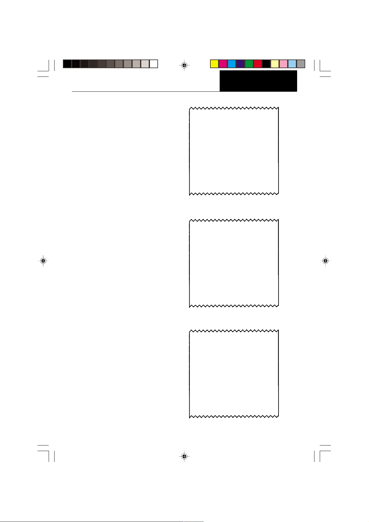
Automatic Calibration Printout
When performing an Automatic calibration with CAL option (GLP submenu of the
Setup Options submenu set to ON), a
printout is made after calibration is completed.
OPERATION
- - - - - AUTO SPAN CAL - - - - - 6/22/95 8:42:24 AM
Bal Id 183
Auto. Cal. completed !
Dif: - 0.00136g
ID 2000000
PR 10000
Name........................................
- - - - - END - - - - -
User Calibration Printout
When performing User calibration with
CAL option (GLP submenu of the Setup
Options submenu set to ON), a printout is
made after calibration is completed.
Calibration Test Printout
When performing a Calibration Test with
with CAL option (GLP submenu of the
Setup Options submenu set to ON), a
printout is available.
- - - - - USER SPAN CAL - - - - - 6/22/95 8:52:21 AM
Bal Id 183
Cal: 200.0000g
Old: 200.0398g
Dif: 0.0398g
Wt. Ref......................................
ID 2000000
PR 10000
Name........................................
- - - - - END - - - - -
- - - - - CAL TEST - - - - - 6/22/95 8:47:02 AM
Bal Id 183
Cal. test completed !
Dif: -0.00045g
ID 2000000
PR 10000
Name........................................
- - - - - END - - - - -
23
Page 30
OPERATION
Menu
Menu
Printing Data (Cont.)
Statistics Printout
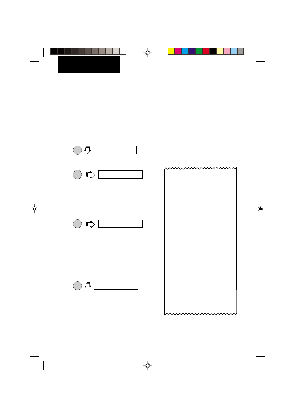
When statistics is enabled, a printout can be made with any of the major balance functions
such as; Percent, Parts Counting, Check Weighing, Animal Weighing and FillGuideTM. Under
the Setup Options menu, Statistics has parameters such as Enable, Standard Deviation,
Mean, Sum, High, Low and Difference which can be turned on or off. Statistics can be printed
any time the balance is operational and statistics is enabled (turned on).
For example, to weigh ten samples and obtain a printout, proceed as follows:
Sampling
PRINT
1.
2. Place the
3.
4. Remove the first sample.
5. Place the
6.
7. Remove the second sample.
NOTE:The weight of each sample is shown
8. Repeat procedure for as many samples
9.
.
to show.
PRINT
ap-
pears and the printer outputs the first
sample weight.
wait for the stability indicator S on the
display to show.
PRINT
ap-
pears and the printer outputs the second
sample weight.
on the display and printed. Maximum
sample size = 256.
as required.
PRINT
to end
the sampling procedure. Printout completes the data. See sample at right.
sTaRT
firs
t sample on the platform, wait for the stability indicator S on the display
sN 1
second
sample on the platform,
sN 2
sTop
- - - - - START - - - - 6/22/95 1:40:00 PM
1 200.0369 g
2 200.0372 g
3 200.0370 g
4 200.0369 g
5 200.0371 g
6 200.0372 g
7 200.0372 g
8 200.0369 g
9 200.0369 g
10 200.0371 g
- - - - - - - - - - - - - - - - - - - - -- SD Pop. 0.000119
Mean 200.037030
Sum 2000.03720
Max. 200.03720
Min. 200.03690
Diff 0.00030
Finish 1:43:17 PM
Bal Id 183
ID 2000000
PR 10000
Name......................................
- - - - - - END - - - - - -
24
Page 31
Printing Data (Cont.)
Menu
Menu
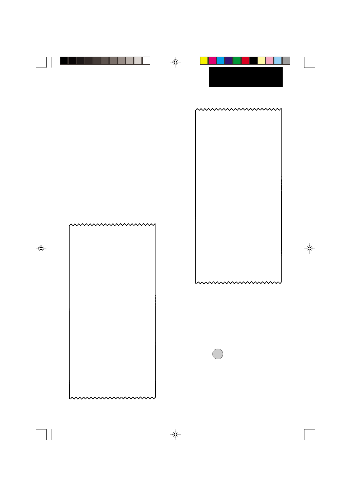
Percent Weighing
Statistical printouts of Percent Weighing
are similar to sampling statistics. Loads
on the balance platform may be displayed
as a percentage of a defined sample. To
obtain a printout in this mode, the balance
must be set up in Percent Weighing. Refer
to basic Sampling procedure for operation. The sample illustration shown at the
right had the balance reference set to
100% using a weight of 25.22573 grams.
- - - - - START - - - - 6/22/95 9:58:00 AM
1 20 Pcs
2 14 Pcs
3 11 Pcs
4 25 Pcs
5 23 Pcs
- - - - - - - - - - - - - - - - - - - - -- SD Pop. 5.31
Mean 18.60
Sum 93.0
Max. 25.0
Min. 11.0
Diff. 14.0
Finish 10:01:00 AM
PC Ref 0.888604 g
Bal Id 183
ID 2000000
PR 10000
Name....................................
- - - - - - - - END - - - - - -
OPERATION
- - - - - START - - - - -
6/22/95 10:53:24 AM
1 100.0%
2 148.9%
3 46.9%
4 70.4%
5 94.0%
- - - - - - - - - - - - - - - - - - - - -- SD Pop. 34.077
Mean 92.040
Sum 460.20
Max. 148.90
Min. 46.90
Diff 102.00
Finish 10:53:39 AM
Bal Id 183
ID 2000000
PR 10000
Name......................................
- - - - - - END - - - - - -
Parts Counting
When the balance is in a Parts Counting
mode, each time a batch of items are
counted, they can be recorded statistically
by pressing
pling procedure. The example shown on
the left used a five piece sample weight of
80.2273 grams.
PRINT
as described in the Sam-
25
Page 32
OPERATION
Menu
Menu
Printing Data (Cont.)
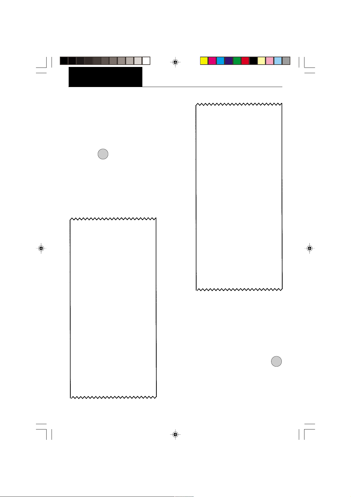
Check Weighing
When the balance is in a Check Weighing
mode, each sample can be checked to print
an under, accept or over weight on the
printout by setting the Print Options parameter Difference to ON. Use the procedure
described in Sampling to obtain data by
pressing
weighed.
- - - - - START - - - - 6/22/95 12:09:29 PM
1 17.28667 g
Fill Dif 7.95202 g
2 31.75109 g
Fill Dif 6.51240 g
3 13.85533 g
Fill Dif 11.38335 g
Fill Dif 174.7985 g
5 28.18002 g
Fill Dif 2.94133 g
- - - - - - - - - - - - - - - - - - - - - - - SD Pop. 71.216407
Mean 58.222062
Sum 291.11031
Max. 200.03720
Min. 13.85533
Diff 186.18187
Finish 1:30:25 PM
Fil Ref 25.23869 g
Bal Id 183
ID 2000000
PR 10000
Name.....................................
PRINT
each time a sample is
4 200.0372 g
- - - - - START - - - - 6/22/95 12:09:29 PM
1 5.96781 g
CW UNDER 0.00397 g
2 14.84395 g
CW OVER 2.98037 g
3 20.50947 g
CW OVER 8.64589 g
4 5.96424 g
CW UNDER 0.00753 g
5 8.93100 g
CW ACCEPT 8.93100 g
- - - - - - - - - - - - - - - - - - - - - - - SD Pop. 5.654601
Mean 11.243294
Sum 56.21647
Max. 20.50947
Min. 5.96424
Diff 14.54523
Finish 12:12:57 PM
Min Ref 5.97177 g
Max Ref 11.86358 g
Bal Id 183
ID 2000000
PR 10000
Name.....................................
- - - - - - END - - - - - -
FillGuide
When the balance is in the FillGuide
mode, each sample can be checked against
the defined FillGuideTM full capacity and to
print the difference on the printout by setting the Print Options parameter Difference
to ON. Use the procedure described in
Sampling to obtain data by pressing
each time a sample is weighed.
TM
PRINT
TM
- - - - - - END - - - - - -
26
Page 33
MENUS
Menu
Menu
MENUS
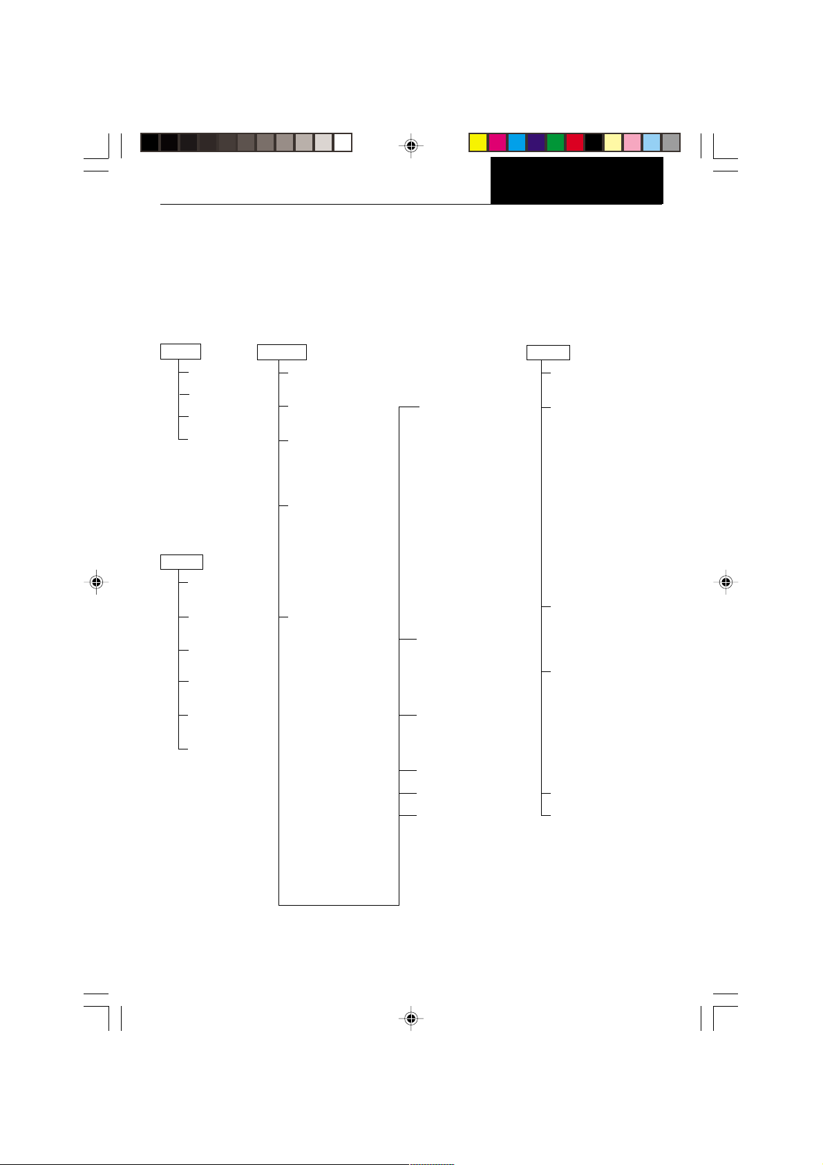
Each submenu of the AP Balance contains numerous selections which can be set for
specific operations. To customize the operation of the balance for specific measurements,
functions and printing, it is necessary to make selections in each menu. The following
illustration identifies the major items in each menu. The factory default settings are shown
in bold type.
CAL
AUTO
USR
TEST
END
USER
RESET
AL
STABILITY
AUTO ZERO
-dUAL-*
END, USER
YES/NO
0, 1, 2
0, 1, 2, 3
ON/OFF
ON/OFF
SETUP
RESET
YES/NO
LFT
ON/OFF
SEL
g, dwt, ct, oz, oz t,
UNIT 1 (grain), t
UNIT 2 (mommes),
UNIT 3 (custom)
FUNCTIONS
None
Percent
Parts Counting
Check Weighing
Animal Weighing
FillGuide
High Point
SETUP OPTIONS
Statistics
Enable
Standard Dev.
Mean
Sum
High
Low
Difference
End, Statistics
Net
Custom Units
Factor
Density
End
GLP
Time
BAL ID #
ID #
Project #
Cal
Name
End, GLP
PRINT
RESET
YES/NO
SETUP OPTIONS
(Cont.)
PC Error
CW Option
Reference Type
Displays Type
End, CW Opts.
AW Option
AW0, AW1, AW2,
AW3
TM
Fill Option
Reference Type
Target Direction
End, Fill Opts.
End
TIME
Type
Set
Adjust
End, Time
DATE
Type
Set
End, Date
LOCKSWITCH
LIST
END, SETUP
COMMUNICATION
Baud
300, 1200,
2400, 4800,
9600
Data Bits
7 or 8
Parity Bit
Odd, Even,
None
Stop Bits
1 or 2
End, Comm.
GLP
ID #
Project #
End
PRINT OPTIONS
Auto Print
Initialize Auto Pt.
Stable Data
Numeric Data
Time
Date
Reference
Difference
End, Print Opts.
LIST
END, PRINT
* For AP250D only.
27
Page 34
MENUS
Menu
Menu
MENU LOCK-OUT PROTECTION
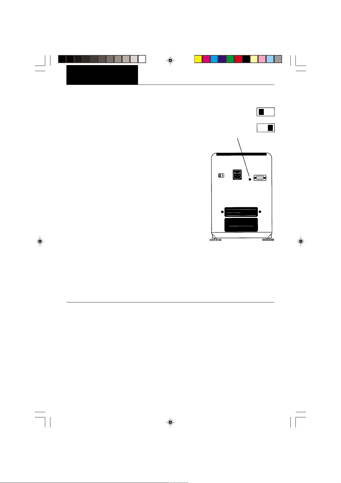
The menus can be locked out to prevent
settings from being changed. When locked
out, Setup and Print menus may still be
accessed for viewing but settings may not
be changed. The word SAFE will be displayed before the menus indicating they
have been locked out.
Before setting menus for Lock or Unlock in
the Loc SW section, this lock-out switch
must be set to Unlock. After selections are
made, set this switch to Lock.
1. Turn the balance OFF.
2. Locate the hole plug next to the
RS-232 Interface connector at the
rear of the balance.
3. Remove the hole plug to access the
switch.
4. Using a small screwdriver, slide the
switch to the right to lock out, or to the
left to unlock menus.
5. Replace the hole plug.
6. Turn the balance ON again.
Unlocked
Remove plug to
access switch.
For verified balances:
Place verification label over hole
with switch in locked position. Fully
verified balances are sealed with the
Setup menu locked out.
Locked
28
Page 35
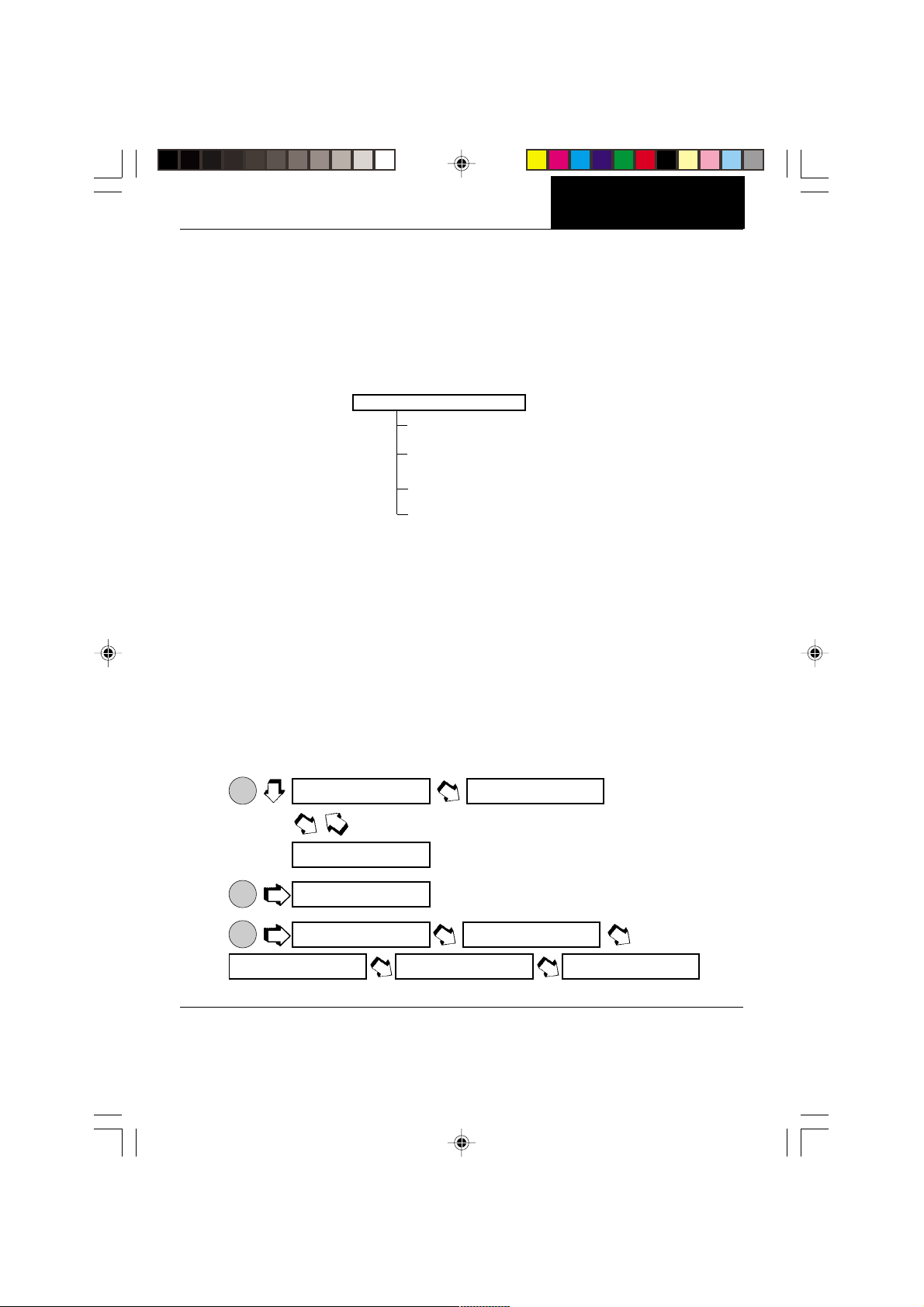
CALIBRATION MENU
Menu
Menu
MENUS
Analytical Plus balances features
method where the balance calibrates itself using internal calibrated masses.
Auto, USER
and
TEST
calibration methods.
Auto
USER
method where the balance can be calibrated using an external mass of known value by
entering that value into the balance.
Test
allows the stored calibration data to be tested
against the internal mass being used for the test. The following figure illustrates the
sequence in which submenus appear on the Calibration menu. Item shown bolded is a
default setting.
CALIBRATION MENU
AUTO
USR
Enter #
TEST
END, Calibration
Calibration Menu Protection
NOTES: 1. Calibration may be locked out to prevent unauthorized personnel from
changing calibration. If calibration has been locked out, you can only access
Test.
2. To lock out calibration menu, after calibration, refer to the section titled
Menu Lock-Out Protection.
Auto Calibration
Auto calibration is used when it is desired to calibrate the balance automatically. Proceed
as follows:
is a
is a
1. Make sure there is no load on the pan and close the chamber doors.
ON
2.
.
TARE
^]emu cal
.
g
NOTE: DO NOT DISTURB THE
BALANCE WHEN -C-
ON
3.
4.
.
TARE
ON
TARE
-c-
CAL
auTo
IIIIIIIIIIIIIIIIIIIIIIIIIIIIIIIIIIIIII I
-c-
IIIIIIIIIIIIIIIIIIIIIIIIIIIIIIIIIIIIII I
-c-
IIIIIIIIIIIIIIIIIIIIIIIIIIIIIIIIIIIIII I
IS DISPLAYED.
IIIIIIIIIIIIIIIIIIIIIIIIIIIIIIIIIIIIII I
-c-
0.00000
s g
29
IIIIIIIIIIIIIIIIIIIIIIIIIIIIIIIIIIIIII I
.
Page 36
MENUS
Menu
Menu
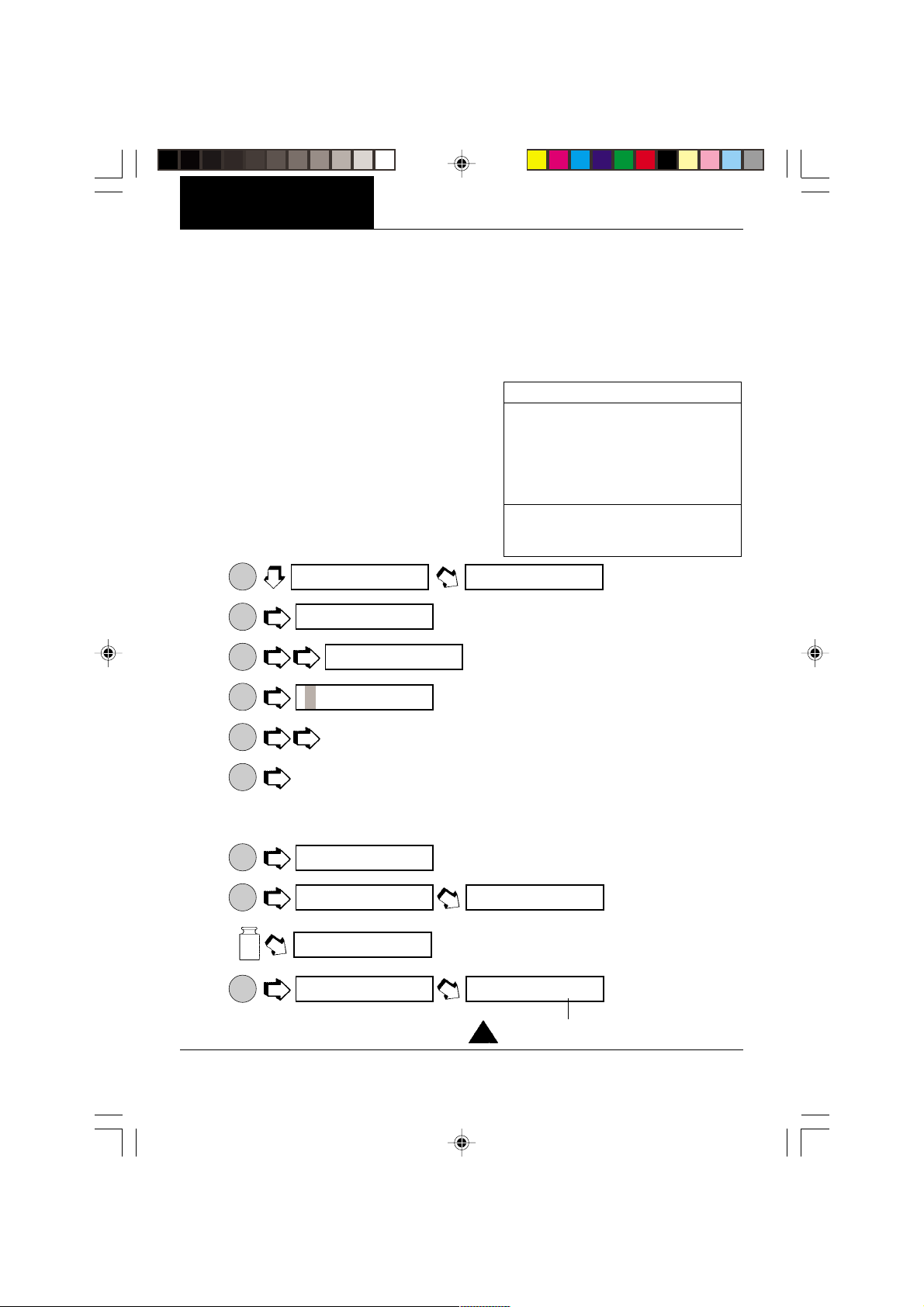
User Calibration
User calibration is used when it is desired to calibrate the balance using a mass of known
value.
NOTE: Before beginning user calibration, make sure masses are on hand.
If you are in the calibration menu and realize masses are not available or you do not want
to calibrate, exit the menus and return to normal weighing.
Refer to the adjacent table for correct mass
values to use with the balance. For optimum
calibration, the exact value of masses should
be known. The value will be entered to four
decimal places during the procedure.
USER CALIBRATION MASSES
MODEL MASS VALUE
AP110S 100 g
AP210S 200 g
AP310S 300 g
Proceed as follows:
1. Make sure there is no load on the pan
and close the chamber doors.
ON
2.
3.
4.
5.
6.
7.
.
TARE
ON
TARE
MODE
.
ON
the value of last calibration mass is displayed.
TARE
MODE
to change value of flashing digit.
ON
to accept value.
TARE
^]emu cal
CAL
auTo
CAL
useR
200.0000
g
AP250D 200 g
Calibration weights must meet or exceed ASTM Class 1 Tolerance. In Europe, use OIML Class E2 weights.
8. Repeat steps 6 and 7 and set the numbers to match the value of the selected calibration
mass.
ON
9.
.
TARE
cal 0
IIIIIIIIIIIIIIIIIIIIIIIIIIIIIIIIIIIIII I
g
10.
11.+
12.
ON
= required mass.
TARE
XXX
grams
ON
.
TARE
cal 200
.
IIIIIIIIIIIIIIIIIIIIIIIIIIIIIIIIIIIIII I
-c-
IIIIIIIIIIIIIIIIIIIIIIIIIIIIIIIIIIIIII I
g
IIIIIIIIIIIIIIIIIIIIIIIIIIIIIIIIIIIIII I
-c-
cal 200
200.0000
s
IIIIIIIIIIIIIIIIIIIIIIIIIIIIIIIIIIIIII I
g
IIIIIIIIIIIIIIIIIIIIIIIIIIIIIIIIIIIIII I
g
ä
= User Calibration Indicator
30
Page 37
MENUS
Menu
Menu
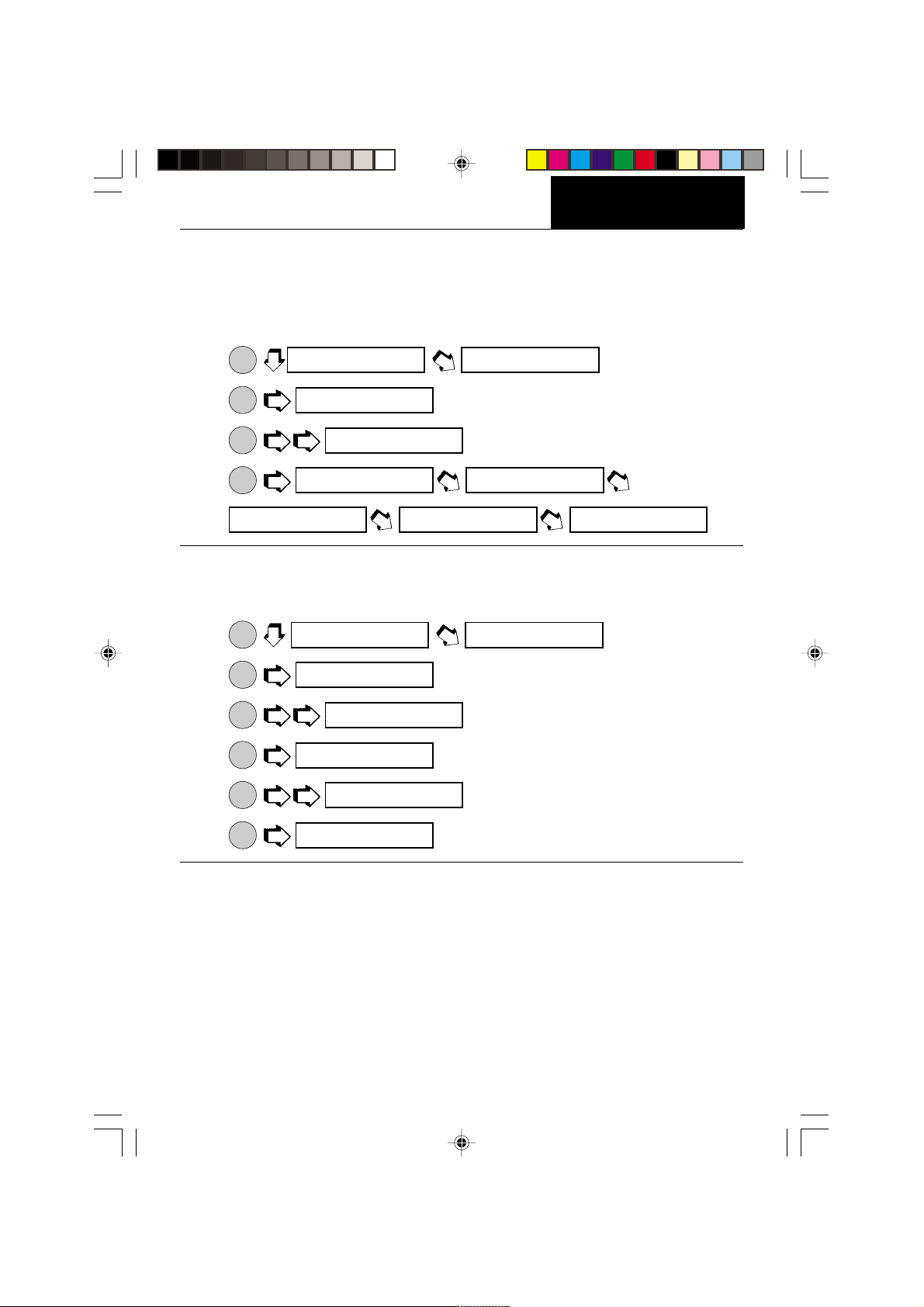
Cal Test
This feature checks the calibration against last stored calibration information. The Cal Error
display indicates the difference since the last automatic calibration.
1. Make sure there is no load on the pan and close the chamber doors.
ON
2.
.
TARE
^]emu cal
3.
4.
5.
ON
TARE
MODE
.
ON
TARE
CAL
0.00000
ERROR
auTo
g
CAL
-c-
CAL
TesT
IIIIIIIIIIIIIIIIIIIIIIIIIIIIIIIIIIIIII I
.
.
Cal End
To exit the calibration menus, proceed as follows:
ON
1.
2.
3.
4.
5.
6.
.
TARE
ON
.
TARE
MODE
.
ON
.
TARE
MODE
.
ON
.
TARE
^]emu cal
CAL
auTo
CAL
eND
cal
eND
MENU
0.00000
IIIIIIIIIIIIIIIIIIIIIIIIIIIIIIIIIIIIII I
gs
IIIIIIIIIIIIIIIIIIIIIIIIIIIIIIIIIIIIII I
-c-
g
0.00000
IIIIIIIIIIIIIIIIIIIIIIIIIIIIIIIIIIIIII I
gs
31
Page 38
MENUS
Menu
Menu
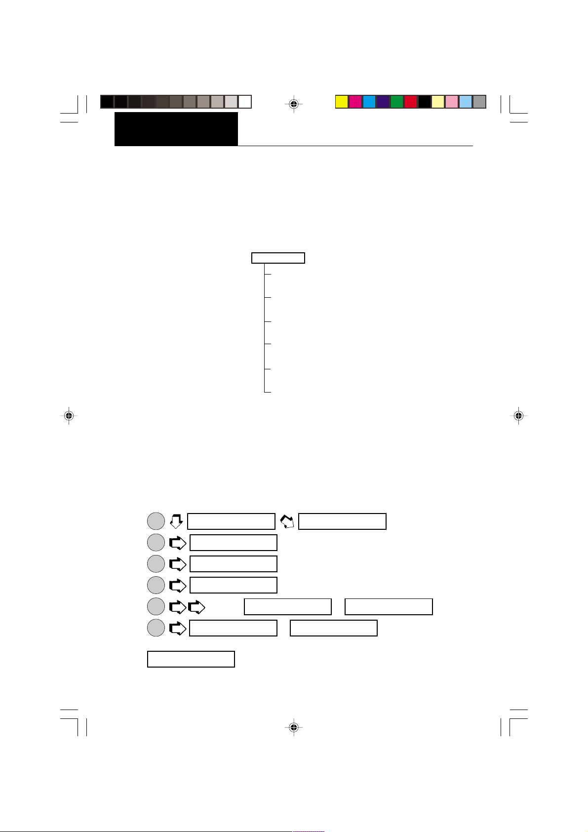
USER MENU
The User menu is used to adapt the balance to environmental conditions. It contains submenus which enable you to turn features on or off, and program balance parameters.
changes all submenus to original factory default settings.
been locked out. AL specifies the averaging level.
Auto Zero
on model AP250D.
sets the automatic zero threshold.
End User
is used to exit the User menu and store the selections. The
Dual,
following figure illustrates the sequence in which submenus appear on the User menu. Items
shown in bold type are the default settings.
USER MENU
RESET
YES/NO
AL
0, 1, 2
STABILITY
0, 1, 2, 3
AUTO ZERO
ON/OFF
-dUAL-
ON/OFF
User Menu Protection
END, User
The User menu may be locked out to prevent unauthorized personnel from changing the
settings. If -SAFE- is displayed, the User menu has been locked out. Settings may be viewed
but not changed. To lock out the User menu, refer to the section titled Menu Lock-Out
Protection.
Reset
Reset
does not appear if menu has
STB
specifies the desired stability range.
when set on, enables dual range function
Reset
This submenu enables you to reset all User menu selections to the
factory default settings:
Averaging Level 1, Stability Range 1, Auto-Zero Tracking ON and Dual Range ON. Reset
does not appear if the menu has been locked out.
ON
1.
TARE
MODE
2.
ON
3.
TARE
ON
4.
TARE
MODE
5.
ON
6.
TARE
signals a
.
.
.
.
to select or .
. If is selected, the balance
eND usR
^]emu
useR
ReseT
yes
yes NO
ReseT yes
long beep
. Reset values are stored only if exited through
.
cal
32
Page 39
MENUS
Menu
Menu
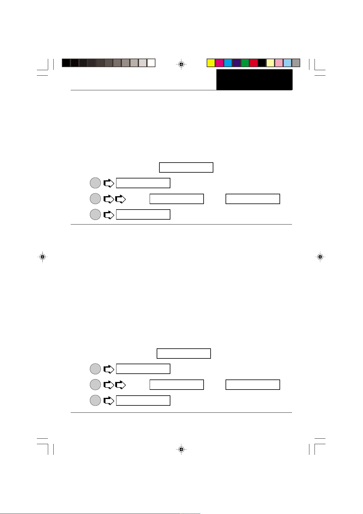
Averaging Level
Averaging level compensates for vibration or excessive air currents. Factory default setting
is shown in bold type.
AL 0 reduced stability, fastest stabilization time
AL 1 normal stability, normal stabilization time
AL 2 more stability, slow stabilization time
NOTE: Averaging level does not affect balance accuracy, but it does affect stabilization
To view or change the averaging level:
1. Access the Averaging Level
ON
2.
3.
4.
.
TARE
MODE
to select through .
ON
.
TARE
al 1
al
al 0 al 2
al
submenu.
Stability Range
The stability range specifies the weighing results must be within a preset tolerance limit for
a certain time to turn the stability indicator ON. When a displayed weight changes beyond
the allowable range, the stability indicator turns OFF, indicating an unstable condition.
Factory default setting is shown in bold type.
Stb 0 Smallest range: stability indicator is ON only when displayed
weight is within a preset tolerance limit for one second.
Stb 1 Normal range.
Stb 2 Larger range.
Stb 3 Largest range: stability indicator is ON when displayed
weight is within a preset tolerance limit for several seconds.
When the RS232 interface is configured to print stable data only, the stability range also
governs data output. Displayed data will only be output if it is within the selected stability
range.
To view or change the stability range:
1. Access the Stability Range
ON
2.
3.
4.
.
TARE
MODE
to select through .
ON
.
TARE
sTB 1
sTB
sTB
sTB 0 sTB 3
submenu.
33
Page 40
MENUS
Menu
Menu
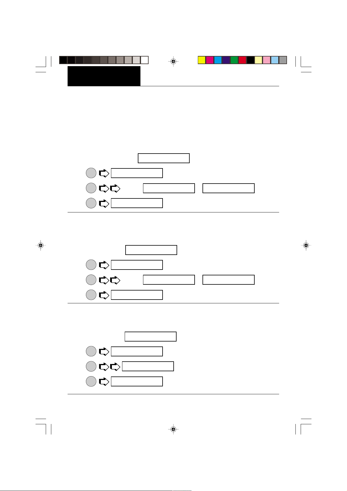
Auto-Zero
Auto-Zero minimizes the effects of temperature changes and shift on the zero reading. The
balance maintains the zero display until the threshold is exceeded. Factory default setting
is shown in bold type.
OFF Turns Auto-Zero OFF.
On Turns Auto-Zero ON.
To view or change the auto-zero setting:
oN
aUTO-0
submenu.
oN off
1. Access the Auto-Zero
ON
2.
3.
4.
.
TARE
MODE
to select or .
ON
.
TARE
aUTO-0
Dual Range Function
Enables dual range operation on model AP250D only. To turn the feature ON, proceed as
follows:
1. Access the Dual
ON
2.
3.
4.
.
TARE
MODE
to select or .
ON
.
TARE
-Dual-
-Dual-
oN
submenu.
oN off
Exiting User Menu
To exit the User menu and store settings, proceed as follows:
1. Access End Usr
ON
2.
3.
4.
.
TARE
MODE
.
ON
.
TARE
0.00000
s g
eND usR
useR
eND
submenu.
MENU
IIIIIIIIIIIIIIIIIIIIIIIIIIIIIIIIIIIIII I
34
Page 41
MENUS
Menu
Menu
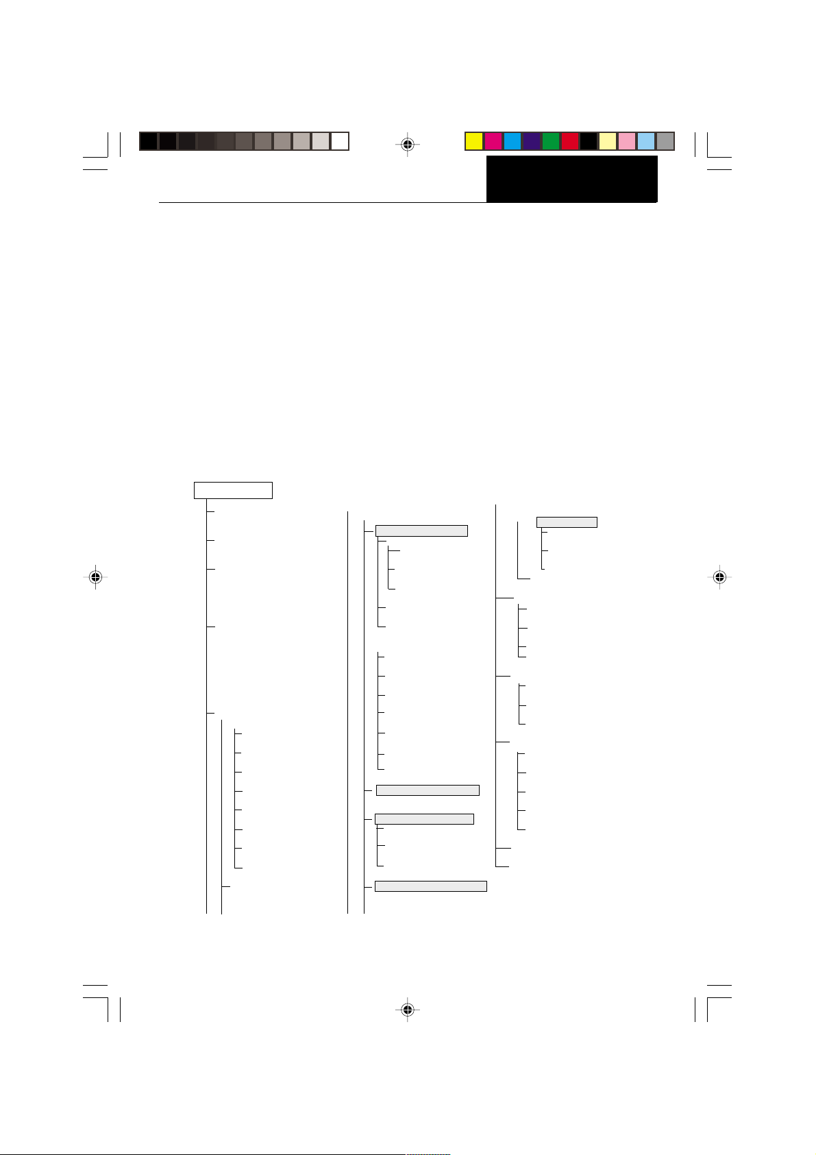
SETUP MENU
The Setup menu is used to customize the operation of the balance for your specific
requirements. It contains submenus which enable you to turn features on or off, and program
balance parameters.
does not appear if menu has been locked out.
operation.
SEL
specialized applications.
can be selected for operation. The functions are: Percent, Parts Counting, Check Weighing,
Animal Weighing, FillGuideTM or High Point. Several of these functions have submenus
under the Setup Options Menu which permit various options to be selected and printed.
Setup Options
tory Practices, Parts Counting Error, Check Weighing Options, Animal Weighing Options, Fill
Options, Time, Date, Lock Switch, List and End. The following figure illustrates the sequence
in which submenus appear on the Setup menu. Areas shaded only appear in the menu if the
appropriate function or weighing unit is selected. Items shown in bold type are the default
settings.
SETUP MENU
RESET
YES/NO
LFT
ON/OFF
SELECTION, UNITS
g, dwt, ct, oz, oz t,
UNIT 1 (grain), t,
UNIT 2 (mommes),
UNIT 3 (custom)
FUNCTIONS
None
Percent
Parts Counting
Check Weighing
Animal Weighing
FillGuide
High Point
SETUP OPTIONS
Statistics
Net
Reset
changes all submenus to original factory default settings.
LFT
sets the balance for type approved
(selection) specifies one of nine weighing units with a custom unit for
Functions
contains six mutually exclusive items, only one at a time
contains submenus as follows: Statistics, Net, Custom Units, Good Labora-
TM
Enable
ON/OFF
Standard Dev.
pop, sample, OFF
Mean
ON/OFF
Sum
ON/OFF
High
ON/OFF
Low
ON/OFF
Difference
ON/OFF
End, Statistics
ON/OFF
SETUP OPTIONS (Cont.)
Custom Units, Unit 3
Factor
Mantissa
Enter #
Exponent
-3, -2, -1, 0, 1, 2, 3
LSD
.5, 1, 2, 5, 10, 100
Density
none, l, ml, fl oz, qt
End
GLP
Time /Date
ON/OFF
Bal ID
ON/OFF
ID #
ON/OFF
Proj. #
ON/OFF
Cal
ON/OFF
Name
ON/OFF
End, GLP1
Parts Counting Error %
.1,. 25, .5, 1, 2.5, 5, OFF
Check Weighing Opts.
Reference.
Ref. Weight, #
Display.
norm, none, sign
End, CW Options
Animal Weighing Options
AW0, AW1, AW2, AW3
SETUP OPTIONS (Cont.)
Fill Options
Ref.
Weight, #
Target
To ref, to zero
End, Fill Options
End, Setup Options
TIME
Set
Enter #
Type
US, Euro
Adjust
End, Time
DATE
Set
Enter #
Type
US, Euro
End, Date
LOCKSWITCH
Cal
YES/NO
User
YES/NO
Setup
YES/NO
Print
YES/NO
End, Locksw
LIST
END, Setup
Reset
35
Page 42
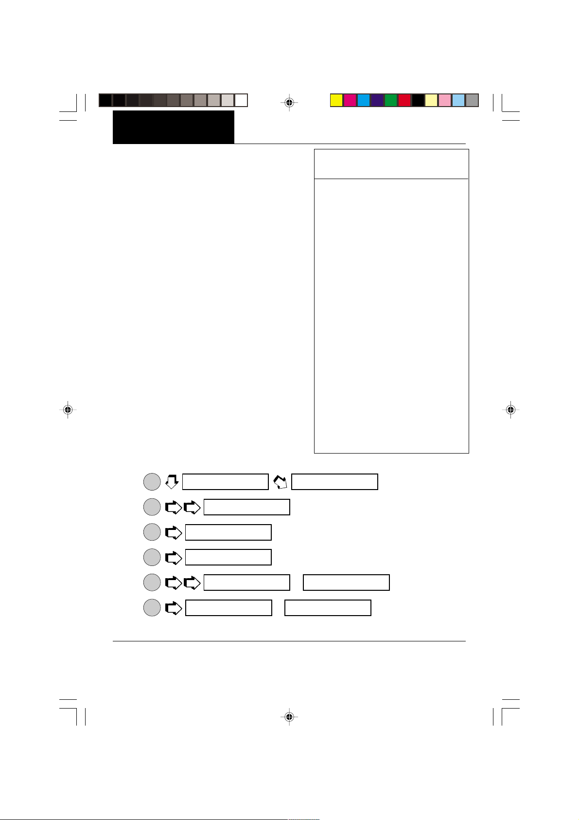
MENUS
Menu
Menu
Setup Menu Protection
The Setup menu may be locked out to
prevent unauthorized personnel from
changing the settings. If -SAFE- is displayed, the Setup menu has been locked
out. Settings may be viewed but not
changed. To lock out the Setup menu, refer
to the section titled Menu Lock-Out Protec-
tion.
Reset
This submenu enables you to reset all
Setup menu selections to the factory default settings shown in the table. Reset
does not appear if the menu has been
locked out.
NOTES:
1. Default settings of the Lockswitch menu
only appear if the hardware Lock-out
switch is set to the locked position.
2. Function related options shown in itailics
in the table only appear if that function
is enabled.
SETUP MENU
FACTORY DEFAULTS
Unit Selection grams
Functions None
Statistics All-Off
Net Off
Conversion Factor
Mantissa 1.000000
Exponent 0
LSD 1
Density None
GLP Off
Animal Weighing AW1
PC Error Level OFF
Check Weighing
Reference Ref Wt.
Display Normal
Fill Options
Reference Ref Wt.
Target To Ref
Time U.S.
Date U.S.
Lockswitch Menu
Cal Yes
User No
Setup Yes
Print No
1.
2.
3.
4.
5.
6.
ON
.
TARE
MODE
.
ON
.
TARE
ON
.
TARE
MODE
or .
ON
. If is selected, the balance
TARE
signals a
^]emu cal
seTup
ReseT
yes
yes NO
ReseT yes
long beep
.
36
Page 43
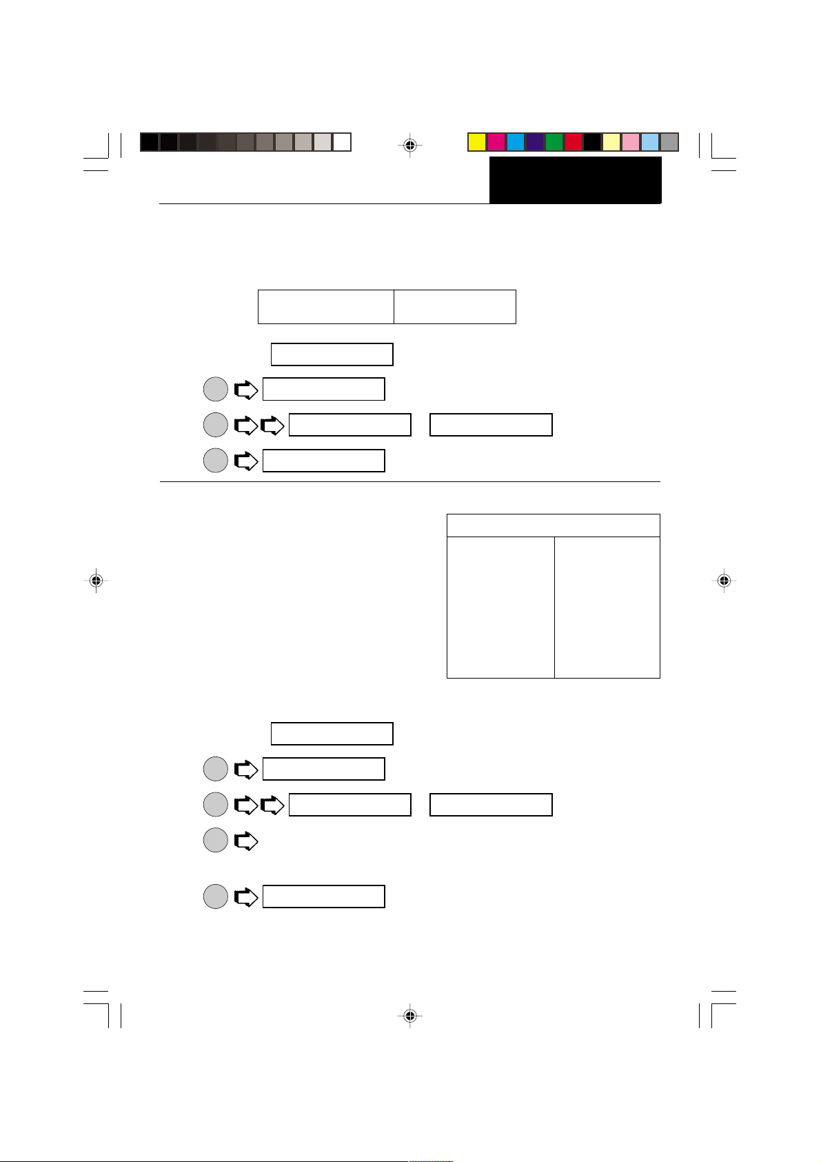
MENUS
Menu
Menu
Type Approved/LFT
LFT can be set to ON or OFF. Selecting ON automatically sets the parameters shown in the
table to conform to type approved requirements. For sealing method, refer to Type Approved
Sealing section. Default setting are shown as follows:
Lockswitch Menu Setup Locked
Print Stable Data Only ON
1. Access the submenu.
ON
2.
3.
4.
.
TARE
MODE
or .
ON
.
TARE
lfT
oN
oN off
lfT
Unit Selection
The Unit Selection (SEL) submenu permits
the selection of weighing units for use during operation. The balance can display
weights in every unit of measure listed in
table. The default setting is shown in bold
type.
NOTE:
If Taels is enabled, see next page before
exiting the menu.
To view or change the various weighing units:
1. Access the
sel
Weighing Units
g Grams
dwt Pennyweight
ct Carats
oz Ounces
ozt Troy ounces
UNIT1 Grains
t Taels (see note)
UNIT2 Mommes
UNIT3 Custom
submenu.
ON
2.
3.
4.
.
TARE
MODE
or .
ON
for next unit status.
TARE
oN"
g
oN" off"
gg
5. Repeat steps 2 through 4 for each unit.
ON
6.
.
TARE
sel
37
Page 44
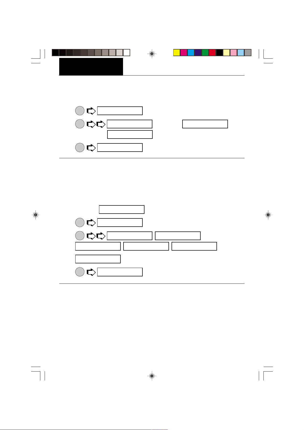
MENUS
Menu
Menu
Unit Selection (Cont.)
Taels
If taels are enabled, choose one of three different taels: Hong Kong, Singapore, or Taiwan.
ON
1.
2.
3.
.
TARE
MODE
(Hong Kong),
(Singapore), or (Taiwan).
ON
.
TARE
oN
Tael 1 Tael 2
Tael 3
oN
t
tt
t
t
Functions
The Functions submenu permits the selection of only one function. These functions are:
Percent, Parts Counting. Check Weighing, Animal Weighing, FillGuideTM, High Point or
None. The default setting is none.
operation.
Selection of a function, other than None or Percent, requires additional selections
to that function be reviewed in the section titled Setup Options.
1. Access the
ON
2.
3.
.
TARE
MODE
, ,
fUNCTN
NONe
c_ı a_ı fIll
Only one function at a time can be selected for balance
submenu.
pcT pc
, , ,
hi pT
ON
4.
.
TARE
fUNCTN
.
38
Page 45
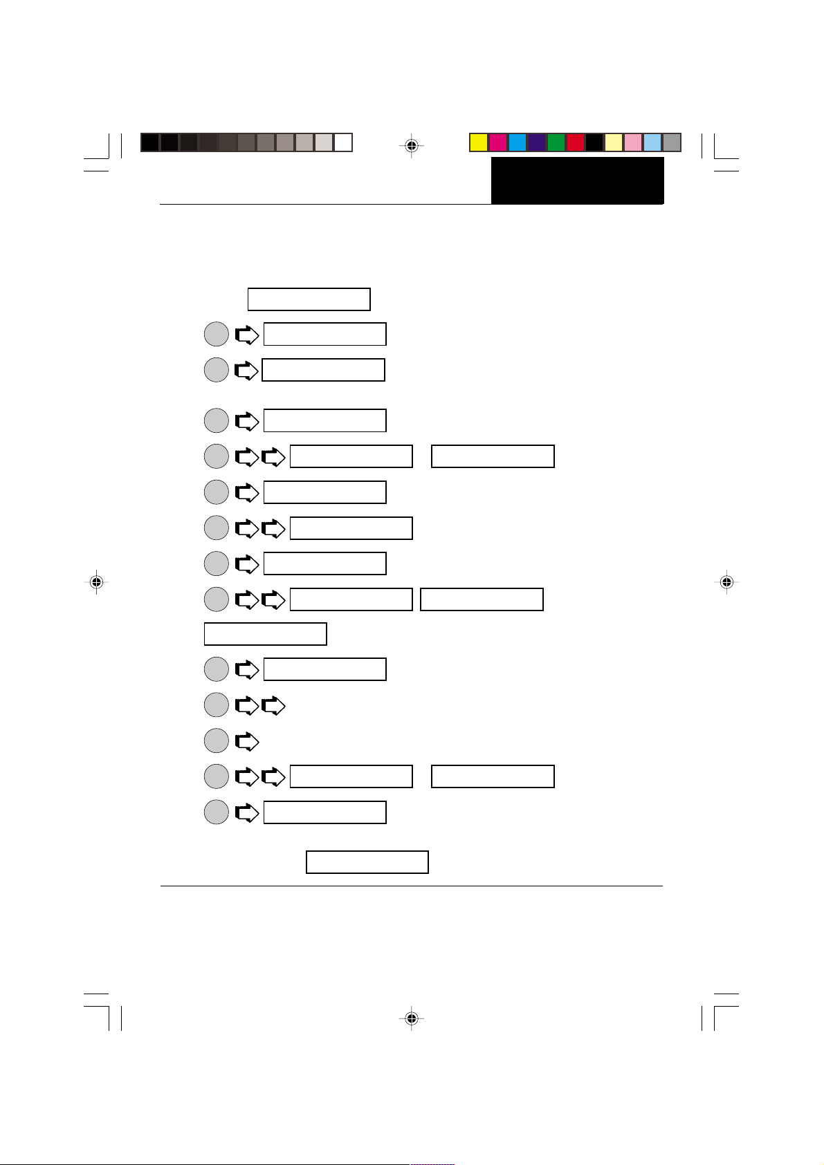
MENUS
Menu
Menu
Statistics
Statistics provides printed display data of: Standard Deviation either population or sample,
Mean, Sum, High, Low and Difference readings. Each can be individually set ON or OFF.
1. Access
ON
2.
TARE
ON
3.
TARE
SETUP
opT ION5
.
. Enable allows the statistics feature to be turned off
sTaT5
emaBle
menu.
without losing the individual settings programmed into memory.
4.
5.
6.
7.
8.
9.
10.
ON
.
TARE
MODE
or .
ON
.
TARE
MODE
.
ON
.
TARE
MODE
, ,
pop.
ON
.
TARE
oN
oN off
emaBle
sTD D
sa^]ple
sa^]ple off
.
sTD D
MODE
11.
12.
13.
14.
to select other parameters.
ON
to accept.
TARE
MODE
or .
ON
.
TARE
^]eam
oN off
15.Continue the same procedure to set Sum, High, Low and Difference parameters and
finish by selecting .
eND
39
Page 46
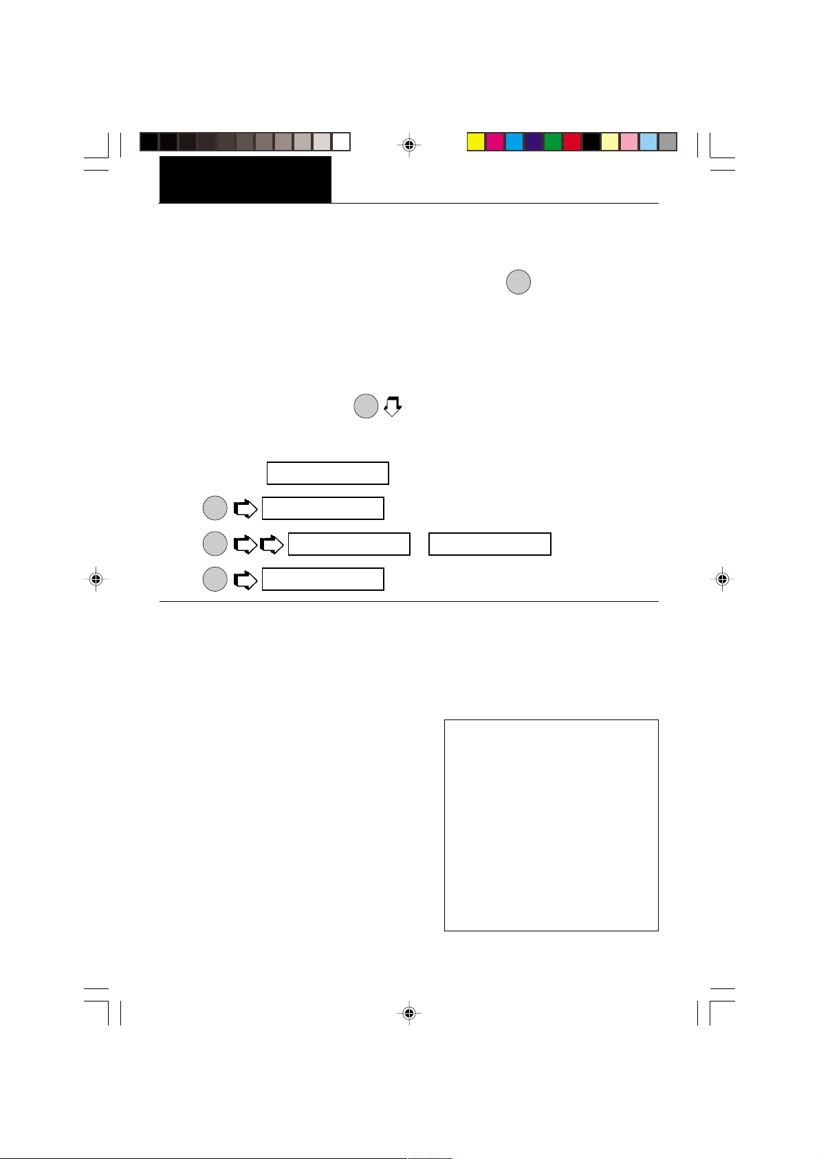
MENUS
Menu
Menu
Net
Weight shown on the display can be referred to as a zero value (gross value) or tare value
(net value). When enabled the display value also has GROSS/NET Indicator turned ON, this
feature will allow you to obtain a zero value by a long press on
Net Weight - the weight of a material or sample after deducting the weight of its packaging
or container with which it had previously been weighed.
Gross Weight - the weight of object or sample (Net Weight) including container or
packaging.
MODE
NOTE: When in a weighing mode,
switches between Gross weight and Net weight.
The Net function can be set either ON or OFF.
ON
. A short press is a tare.
TARE
1. Access the
ON
2.
3.
4.
.
TARE
MODE
or .
ON
.
TARE
meT
oN
oN off
meT
menu under the Setup Options menu.
Custom Unit or Volume Selection
Custom Unit is enabled when Unit 3 under Unit Selection is selected. When you need to
display weight measurements in a weighing unit other than those provided standard with the
balance, this feature can be used to create your own custom weighing unit. It permits you
to enter a conversion factor which the balance will use to convert grams to the desired unit
of measure.
Conversion Weight Weight
Factor x in = in
grams custom unit
Conversion factors are expressed in scientific notation and entered into the balance in
three parts:
• a number between 0.1 and 1.999999
called the mantissa
• a power of 10 called the exponent
• a least significant digit (LSD)
SCIENTIFIC NOTATION
Number
Between
Conv. 0.1 and Power Man-
Factor 1.999999 of 10 tissa Exp.
123.4 = .1234 x 1000 = .1234 x 10
12.34 = .1234 x 100 = .1234 x 10
1.234 = .1234 x 10 = .1234 x 10
.1234 = .1234 x 1 = .1234 x 10
.01234 = .1234 x .1 = .1234 x 10
.001234 = .1234 x .01 = .1234 x 10
.000123 = .123 x .001 = .123 x 10
3
2
1
0
-1
-2
-3
40
Page 47
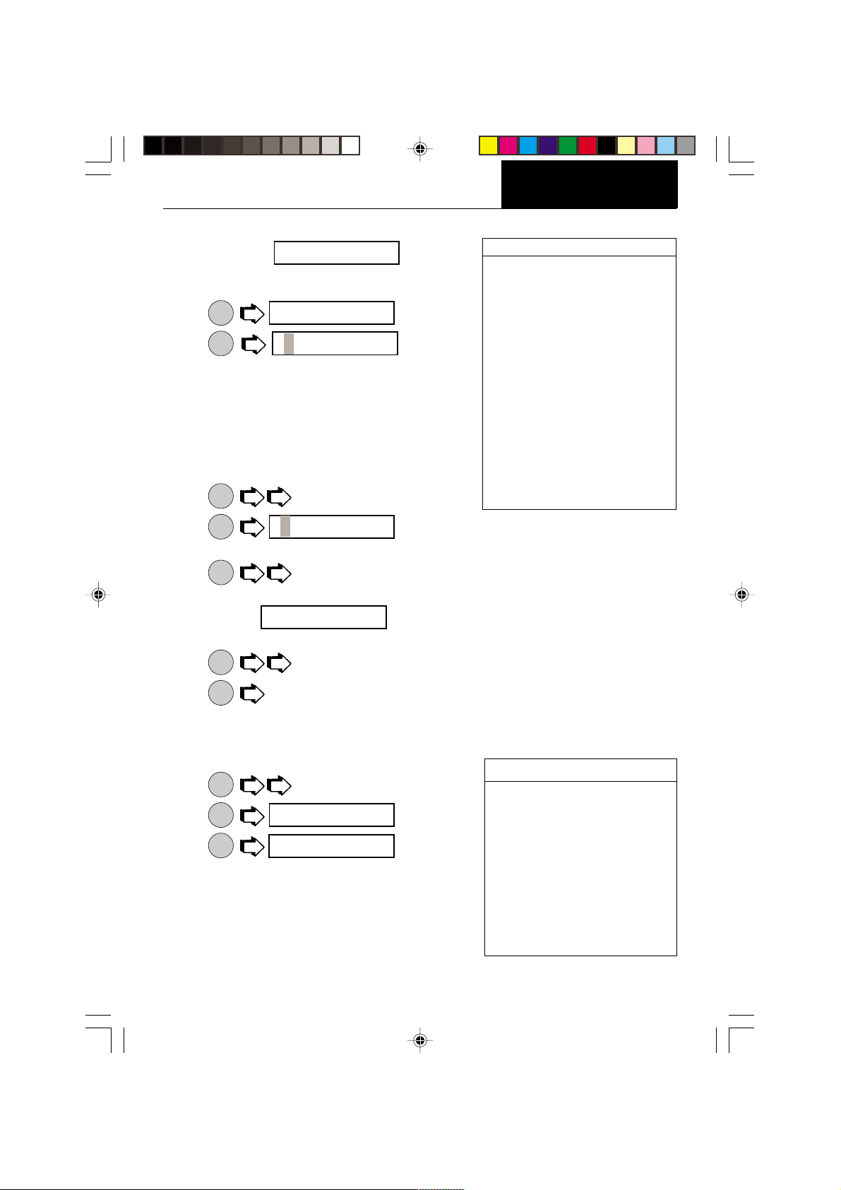
MENUS
Menu
Menu
Custom Unit or Volume Selection (Cont.)
1. Access the
submenu under the Setup Options
cuNIT
UNITS
E-3 Moves decimal point 3
menu.
ON
2.
3.
.
TARE
ON
. The
TARE
facTOR
1.000000
UNITS
E-2 Moves decimal point 2
E-1 Moves decimal point 1 place
mantissa of the current conversion is
displayed. The mantissa of the current
E0 Leaves decimal point in
conversion factor is displayed. This is a
number between 0.1 and 1.999999 with
E1 Moves decimal point 1 place
the first digit flashing. For conversion
factors outside of this range, the exponent will be used to move the decimal
E2 Moves decimal point 2
point.
MODE
4.
5.
changes first digit.
ON
TARE
1.000000
. next digit flashes.
UNITS
E3 Moves decimal point 3
6. Repeat steps 4 and 5, and set value of all digits.
PRINT
7.
to backup for errors.
8. After the last digit is entered, the display indicates the current exponent preceded by
the letter
e 0
UNITS
. There are 7 exponent value which you can choose
from (see table).
MODE
9.
10.
to change the exponent.
ON
. When released, the display shows the current least significant digit. The
TARE
least significant digit is the digit in the last decimal place on the display. The selection
you make causes the balance to count by 1’s, 2’s or 5’s in this position. There are 6
LSD settings you can choose from (see
table).
MODE
11.
12.
13.
to change the LSD.
ON
.
TARE
MODE
. Den-
facTOR
DeNsITy
sity permits the selection of the density of
a liquid by measuring the volume by
weight. If the Factor is the density of a
liquid, the appropriate unit of volume can
be selected for printing.
EXPONENTS
places to the left.
places to the left.
to the left.
normal position.
to the right.
places to the right.
places to the right.
LSD’s
LSD .5* Adds one decimal
place display counts by 5’s.
LSD 1 Display counts by 1’s.
LSD 2 Display counts by 2’s.
LSD 5 Display counts by 5’s.
LSD 10 Display counts by 10’s.
LSD 100 Display counts by
100’s.
* Sensitivity to vibration is in-
creased with this LSD setting.
41
Page 48
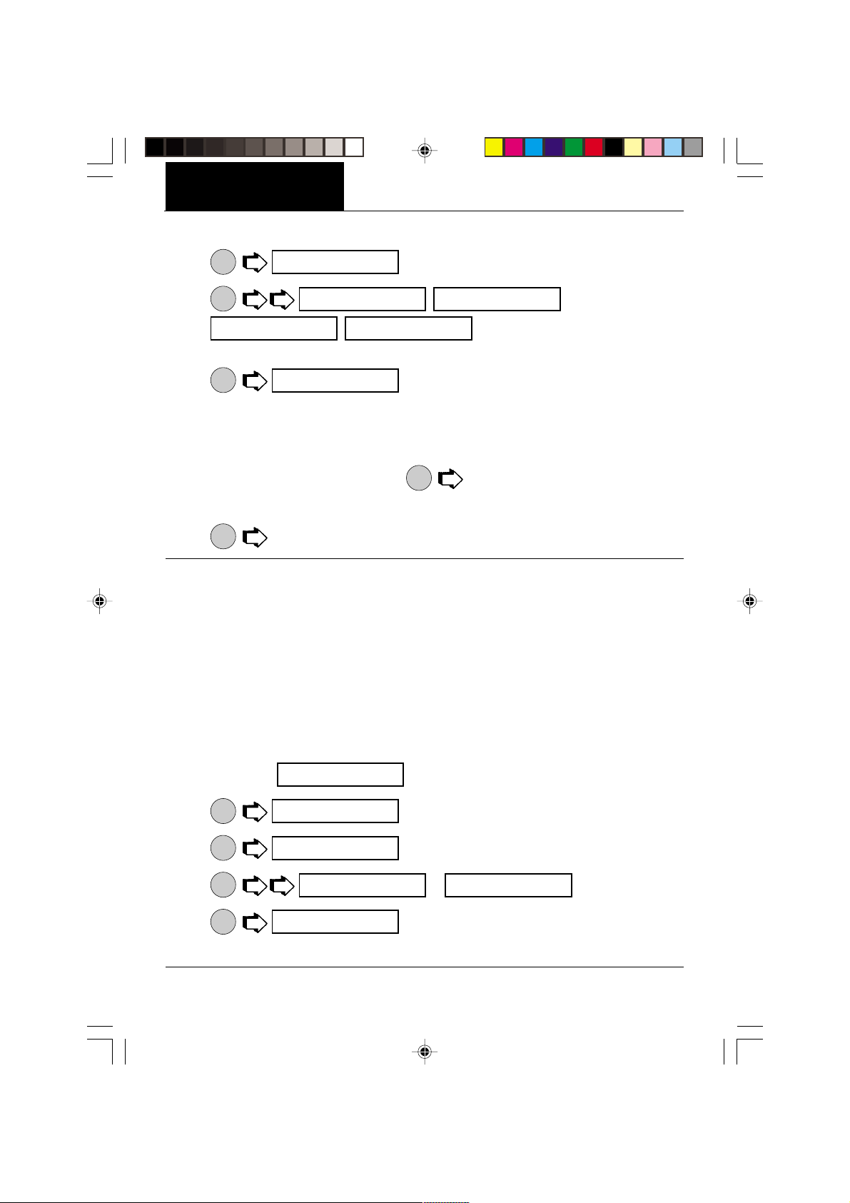
MENUS
Menu
Menu
Custom Unit or Volume Selection (Cont.)
14.
15.
ON
.
TARE
MODE
, ,
fl 02 ·uaRT
NONe
lITeR ^]l
, . Selecting NONE disables the
volumetric units.
16.
ON
.
TARE
DeNsITy
NOTE: To use this function the printer must be on and all communication parameters
must be set first.
Operating Procedure
ON
1. Place a container on the platform,
to tare the container .
TARE
2. Fill the container.
PRINT
3.
, printer will now print out quantity of selected unit of measurement.
Good Laboratory Practices
Good Laboratory Practices (GLP) submenu allows the selection of Time, Balance Identification Number, Identification Number, Project Number, Calibration and Name data to be
printed. The purpose of this submenu is to permit the printing of the above selected items.
These items are not displayed. The default setting is off.
When an external printer is used, and all items are set ON and the balance is calibrated, the
printer will print out calibration data for audit trail purposes and will indicate date, and time.
The Balance ID number is entered through the RS232 command xxxxID. It should be noted
that the ID number and Project number must be entered in the Print/GLP submenu before
printed data is available. Since all of the settings for the GLP submenu are done in a similiar
manner, only one example is shown.
1. Access the
ON
2.
3.
4.
5.
.
TARE
ON
.
TARE
MODE
or .
ON
.
TARE
9lp
TI^]e
oN
TI^]e
submenu under
oN off
SETUP
Options menu.
6. Repeat steps above for Balance ID#, ID#, Project#, Calibration and Name.
42
Page 49
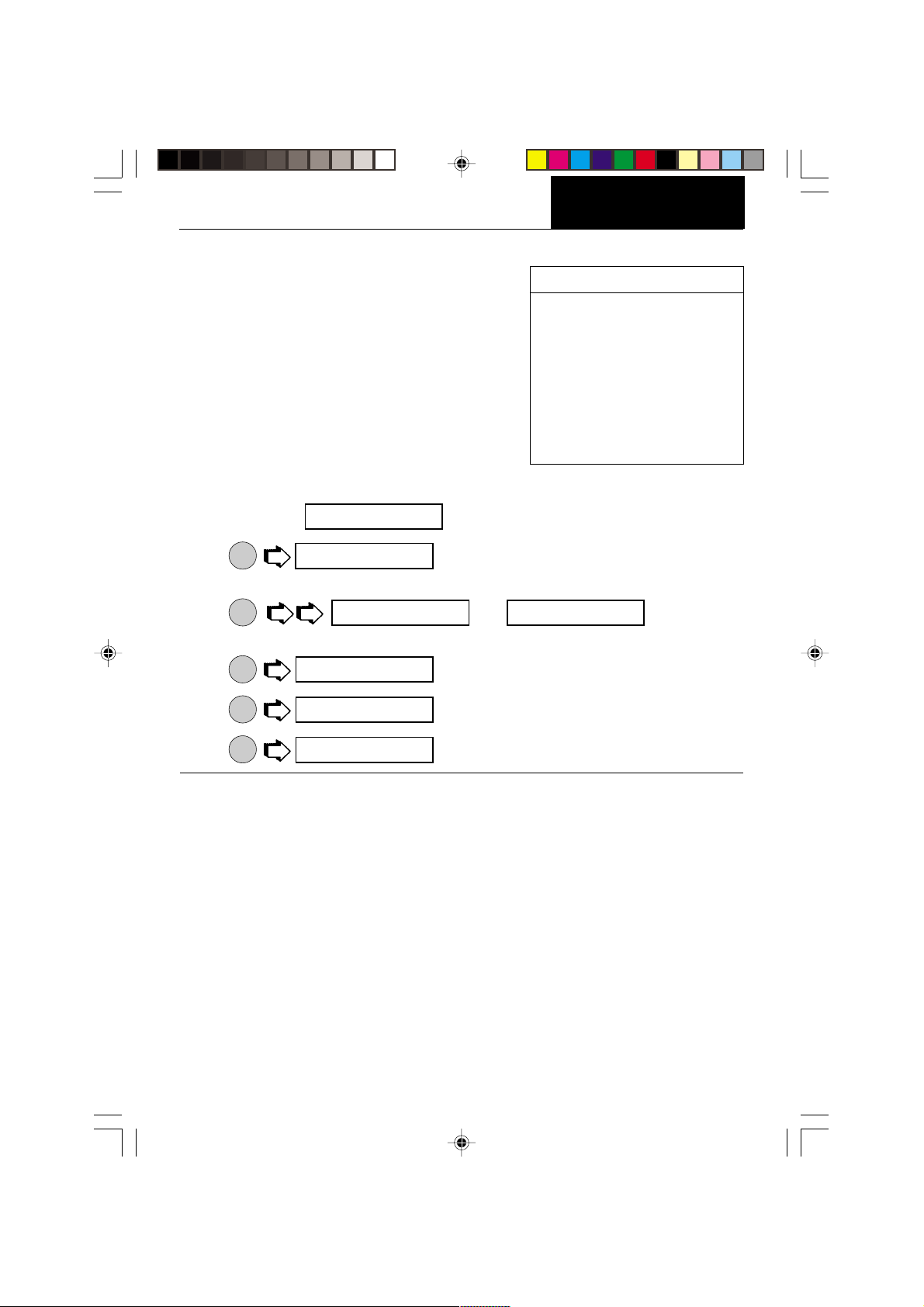
Parts Counting Error
Menu
Menu
MENUS
Parts counting Error is enabled only when the
Parts Counting Function is selected.
The parts counting error level is the level of
accuracy you consider acceptable for parts
counting results. The adjacent table lists error
levels that you can choose from. The default
setting is shown in bold type.
EXAMPLE: With 5 Pct selected, 100 parts on
the platform may yield a displayed count from
95 to 105 parts.
To view, change or disable the PC Error Level:
PC
1. Access the
ON
2.
indicates percentage of acceptable error. Settings
TARE
pC eRR
seT .1
%
submenu under the Setup Option submenu.
are shown in table.
MODE
3.
••• to change the
seT .1 seT 5
%%
percentage error limits,
ON
4.
TARE
MODE
5.
PC
when the desired setting is reached.
.
pC eRR
eND
ERROR LEVELS
OFF Disables error level limits.
.1 % ±0.1% acceptable error.
.25 % ±0.25% acceptable error.
.5 % ±0.5% acceptable error.
1 % ±1.0% acceptable error.
2.5 % ±2.5% acceptable error.
5 % ±5.0% acceptable error.
ON
6.
.
TARE
SETUP
opT ION5
Check Weighing Options
Check Weighing is enabled only when the Check Weighing Function is selected. This feature
may be used for check weighing or package weight control in any one of the available
weighing units. When in use, the display will show the relationship between the load on the
pan, and the selected target weight. The bar graph will visibly display where the weight of
the load falls in relationship to the under, acceptable, and over limits. The balance also
displays UNDER, ACCEPT, and OVER messages as appropriate. The default settings are:
Reference = Reference weight, Display = normal.
Two choices are provided for programming the Reference Weight. One choice is the use of
a mass (package, container, etc,) and the other is a number which can be entered as a high
and low limit.
Three choices are provided for programming the display: normal, none, and sign. Sample
displays are shown on the next page.
43
Page 50
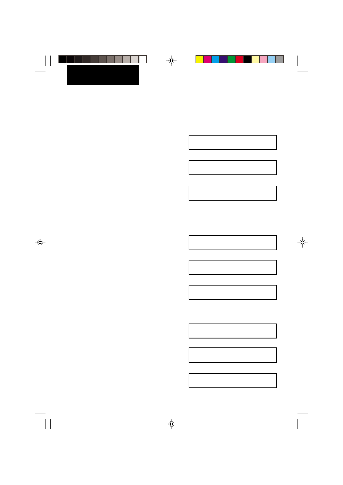
MENUS
Menu
Menu
SAMPLE DISPLAYS
NOTE: Samples of the displays for check weighing are shown as follows using a reference
weight of 50 grams. The over limit was set at 55 grams, and the lower limit was set at 45
grams.
NORMAL DISPLAYS
When normal is selected, the display indicates the actual weight.
NONE DISPLAYS
When none is selected, the numeric section of the display is blank if the values
exceed the limits. Numbers appear only if
they are within the limits.
55.0000
s
50.00000
s
45.00000
s
55.00000
s
50.00000
s
UNDER
55.00000
s
UNDER
OVER
IIIIIIIIIIIIIIIIIIIIIIIIIIIIIIIIIIIIIIIIII
g
áà
ACCEPT
IIIIIIIIIIIIIIIIIIIIIIIIIIIIIIIIIIIIIIIIII
áà
IIIIIIIIIIIIIIIIIIIIIIIIIIIIIIIIIIIIIIIIII
áà
OVER
IIIIIIIIIIIIIIIIIIIIIIIIIIIIIIIIIIIIIIIIII
g
áà
ACCEPT
IIIIIIIIIIIIIIIIIIIIIIIIIIIIIIIIIIIIIIIIII
áà
IIIIIIIIIIIIIIIIIIIIIIIIIIIIIIIIIIIIIIIIII
g
áà
SIGN DISPLAYS
When sign is selected, the display spells in
words; HIGH, LOW or ACCEPT with no
weight values showing.
44
hi6h
s
accepT
s
lo_ı
s
UNDER
ACCEPT
OVER
IIIIIIIIIIIIIIIIIIIIIIIIIIIIIIIIIIIIIIIIII
g
áà
IIIIIIIIIIIIIIIIIIIIIIIIIIIIIIIIIIIIIIIIII
g
áà
IIIIIIIIIIIIIIIIIIIIIIIIIIIIIIIIIIIIIIIIII
g
áà
Page 51
MENUS
Menu
Menu
Check Weighing Options (Cont.)
The following procedure describes how to set up the balance for all choices. Before starting,
the Check Weighing option must have been selected under the Functions submenu.
1. Access the
ON
2.
3.
4.
(reference).
TARE
ON
(reference weight).
TARE
MODE
. If REF WT is
c_ı opT
submenu under the Setup Options submenu.
Ref
Ref _ıT
Ref _ıT NU^]BeR
selected, a sample reference is used later to set the weight parameter into the balance.
If NUMBER is selected, a number representing the sample weight has to be entered
manually. See section titled Check Weighing.
5.
6.
7.
8.
9.
10.
11.
ON
.
TARE
MODE
.
ON
.
TARE
MODE
, , .
ON
.
TARE
MODE
.
ON
.
TARE
Ref
Display
NOR^]al
NOR^]al NONe si9m
Display
eND
c_ı opT
12.
13.
MODE
.
ON
.
TARE
eND
SETUP
opT ION5
45
Page 52
MENUS
Menu
Menu
Animal Weighing Options
Animal Weighing Options is enabled only when Animal Weighing Function is selected. The
balance samples the weight data for a variable sampling interval and processes the data to
filter out the instabilities by the live animal.
The strength of the filtering activity as well as the duration of the sampling period can be
adjusted by selecting one of four AW OPT levels, 0 through 3. 0 is the least amount of
processing, as well as the shortest sampling interval while level 3 is the maximum processing
amount and the longest sampling interval. AW3 should be used for an active subject. The
default setting is AW1.
1. Access the submenu under the Setup Option submenu.
ON
2.
3.
4.
5.
6.
.
TARE
MODE
, ,
a_ı 3 a_ı 0
ON
.
TARE
MODE
.
ON
.
TARE
a_ı opT
a_ı 1
a_ı 1 a_ı 2
a_ı opT
eND
SETUP
opT ION5
, for desired sensitivity.
Fill Option
Fill Option provides two choices for a reference weight (similar to check weighing). Either a
mass can be placed on the pan and used as a reference weight or a number can be entered
to establish the weight value. Both methods are used to establish a reference for a 100% bar
graph reading. Target parameter provides two choices, one is fill to the reference, the other
to zero. The following procedure describes how to set up the balance for all choices. Before
starting, the Fill Function must have been selected.
MODE
1.
to select the desired weighing unit, g, dwt, oz, etc.
2. Access the
ON
3.
4.
(reference).
TARE
ON
(reference weight).
TARE
f IllopT
Ref
Ref _ıT
submenu under the Setup Options submenu.
46
Page 53
Fill Option (Cont.)
Menu
Menu
MODE
5.
6.
. If REF WT is
selected, a sample reference weight is used later to set the weight parameter into the
balance. If NUMBER is selected, a number representing the desired sample weight
has to be entered. Select either REF WT or NUMBER.
ON
.
TARE
MENUS
Ref _ıT NU^]BeR
Ref
MODE
7.
. When target is selected, the balance will show the
TaR9eT
normal weight of the object on the pan.
ON
8.
9.
.
TARE
MODE
or . When zero is se-
TO Ref TO 2eR0
lected, the balance indicates the weight as a negative number after the reference is set
in the main menu. When an object is placed on the balance that weighs exactly what
the reference was set to, the display shows zero with a full bar graph.
10.
11.
12.
13.
14.
ON
.
TARE
MODE
.
ON
.
TARE
MODE
.
ON
.
TARE
TaR9eT
eND
f IllopT
eND
SETUP
opT ION5
Time
Time is a feature which enables the balance to be set to the current time in either U.S.A.
standards (12 hour periods) or European/Military standards (24 hour periods). The default
setting is US Standard. To enter time, proceed as follows:
1. Access the
ON
2.
3.
4.
5.
.
TARE
ON
.
TARE
MODE
or .
ON
.
TARE
T I^]e
Type
us
Type
submenu which is under the Setup menu.
us euRo
47
Page 54
MENUS
Menu
Menu
Time (Cont.)
6.
7.
8.
9.
10.
11.
12.
13.
MODE
.
ON
first two digits are flashing.
TARE
MODE
or
ON
flashes the last two digits.
TARE
NOTE:
MODE
MODE
PRINT
or
ON
to accept. AM or PM is flashing, A for AM, P for PM.
TARE
to select AM or PM.
ON
.
TARE
seT
12 00 a
MODE
to change flashing digits to current local hour.
1 00 a
will back up display.
MODE
changes minutes display.
seT
Adjust
Adjust is a feature which enables the internal clock of the balance to be corrected + or - 59
seconds a day. The internal clock is accurate to within 8 seconds a day. To enter or subtract
time, proceed as follows:
1. Access the
aD∆`usT
submenu which is under the Time submenu.
ON
2.
3.
4.
5.
6.
7.
8.
. First digit is flashing.
TARE
MODE
to change first digit (ten seconds) from 0 to +5 or -5.
ON
, seconds digit is flashing.
TARE
MODE
to change seconds from 0 to 9.
ON
.
TARE
MODE
.
ON
.
TARE
aD` 00
aD` 00
aD∆`usT
eND
T I^]e
48
Page 55
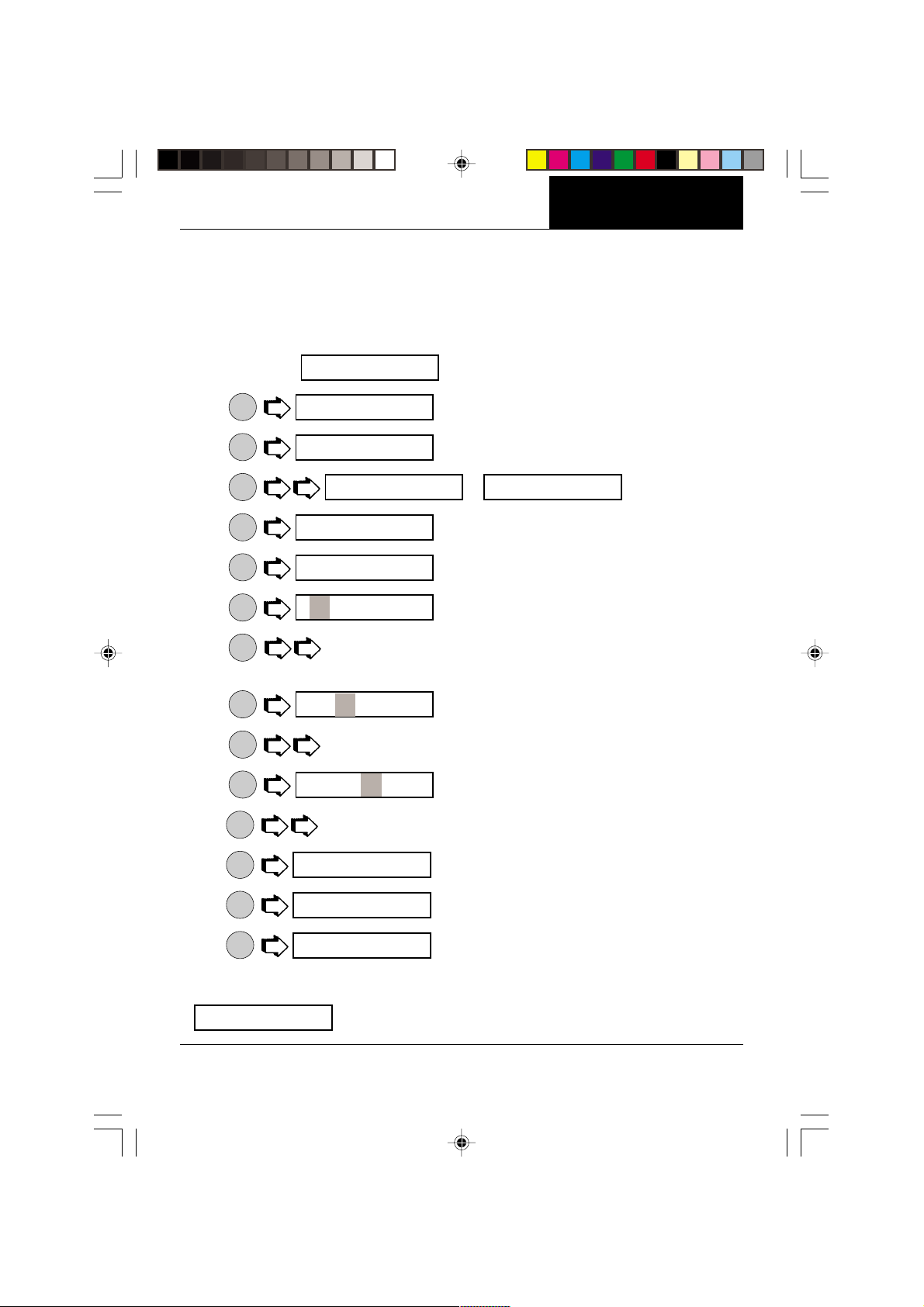
MENUS
Menu
Menu
Date
Date is a feature which enables the balance to be set to a U.S.A. date standard or European
date standard. U.S. standard has the month, date followed by the year each separated by
(/) in the printout. The European date standard has the day first, followed by the month and
then the year each separated by a period. The default setting is US Standard.
1. Access the
ON
2.
3.
4.
5.
6.
7.
8.
.
TARE
ON
.
TARE
MODE
or .
ON
.
TARE
MODE
.
ON
flashes first two digits.
TARE
MODE
to change the first flashing digit to current month for US or day for
European standard.
ON
9.
10.
11.
.
TARE
MODE
to change flashing digit.
ON
.
TARE
DaTe
Type
us
Type
seT
00.00.00
3.00.00
3.1.·5
submenu which is under Setup menu.
us euRo
MODE
12.
13.
14.
15.
to change year.
ON
.
TARE
MODE
.
ON
.
TARE
seT
eND
DaTe
NOTE: At power up, if Time in the GLP submenu is set to ON, the display flashes
SET
T I^]e
for about 1.5 seconds to prompt setting of time and date.
49
Page 56
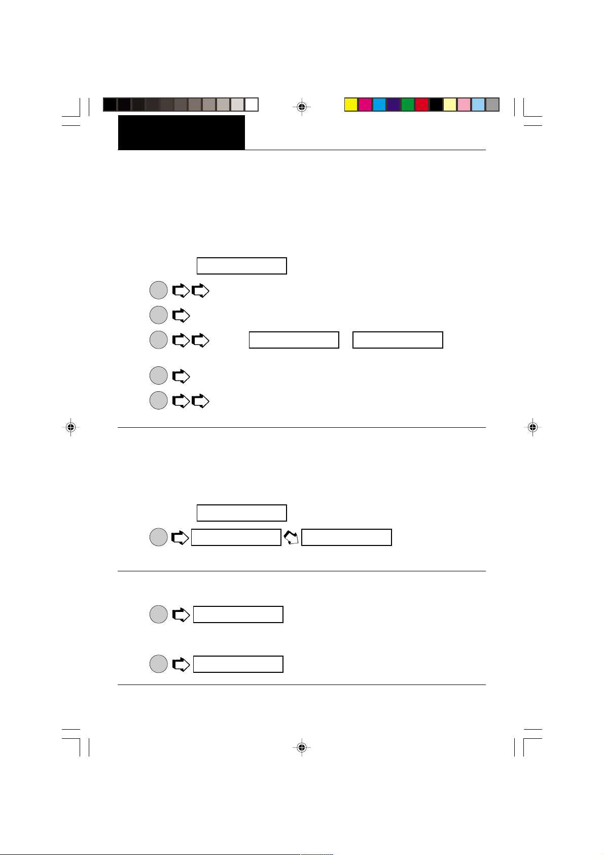
MENUS
Menu
Menu
Lockswitch
Lockswitch enables you to lock out one or more menu selections. Each menu can be
individually locked on or off
Setup and Print menus can be individually locked on or off by selecting the appropriate
menu and then locked by the switch located under the front of the control panel. See Menu
Lockout Section. Cal Test under Calibration remains functional with the Lockswitch On or
Off. Before performing the lockout procedure, decide which functions of the balance are to
be locked on or off.
after all functions have been set
. The Calibration, User,
1. Access the
MODE
2.
3.
4.
to access either Calibration, User, Setup or Print menus.
ON
to access selected desired menu.
TARE
MODE
to select or .
locs_ı
submenu which is under the Setup menu.
yes NO
YES = locked, NO = not locked.
ON
5.
6.
to accept.
TARE
MODE
to change to other menus.
7. To change other menus, repeat steps 2 through 5.
List
This submenu can be used to output a listing of current menu settings via the RS232
interface. When selected, all menu settings for the User, Setup and Print menus will be
output either to an external printer or computer. To use this feature, your balance must be
connected to a computer or printer.
1. Access the
ON
2.
. The display indicates a
TARE
l IsT
l IsT . . . . . . .
series of dots traveling right to left when the balance is sending information.
submenu under the Setup or Print menus.
Exit Setup Menu
MODE
1.
.
NOTE:If any Setup parameter is different from previous settings, indicator SETUP in the
display flashes while the balance is storing new settings. Proceed with next step.
ON
2.
.
TARE
SETUP
seTup
eND
50
Page 57
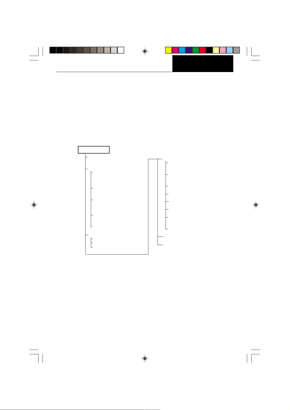
MENUS
Menu
Menu
PRINT MENU
The Print menu provides a number of options which includes: reset, communications, good
laboratory practices, print options, and list.
menu to factory default settings.
parity bit type and stop bits.
Communication
GLP
Good laboratory practices permits the entering of your own
identification number and project number which shows up on printing.
disables Auto print feature, specifies time interval for automatic output of displayed data and/
or exclude a range of weights from being output. The following items can be turned on or off:
Stable data-only feature, numeric only or full display data for output, time and date. Items
shown in bold type are default settings. Items shown in italics in the print menu below appear
only if the appropriate Functions are turned on.
PRINT MENU
RESET
YES/NO
COMMUNICATION
Baud
300, 1200, 2400,
4800, 9600
Data Bits
7 or 8
Parity Bit
Odd, Even, None,
1, 0
Stop Bits
1 or 2
End, Comm.
GLP
ID #
Project #
End,GLP
Reset
sets all submenus contained in the Print
specifies baud rate, number of data bits,
Print Options
PRINT OPTIONS
Auto Print
Cont, interval,
on stb,off
Initialize Auto Print
Interval, non print lo,
non print hi
Stable Data
ON/OFF
Numeric Data
ON/OFF
Time
ON/OFF
Date
ON/OFF
Reference
ON/OFF
End, Print Options
LIST
END, PRINT
Enables/
Print Menu Protection
The Print menu may be locked out to prevent unauthorized personnel from changing
settings. If SAFE is displayed, the Print menu has been locked out. Settings may be viewed
but not changed. To lock out the Print menu or unlock, refer to the section titled Menu LockOut Protection.
51
Page 58
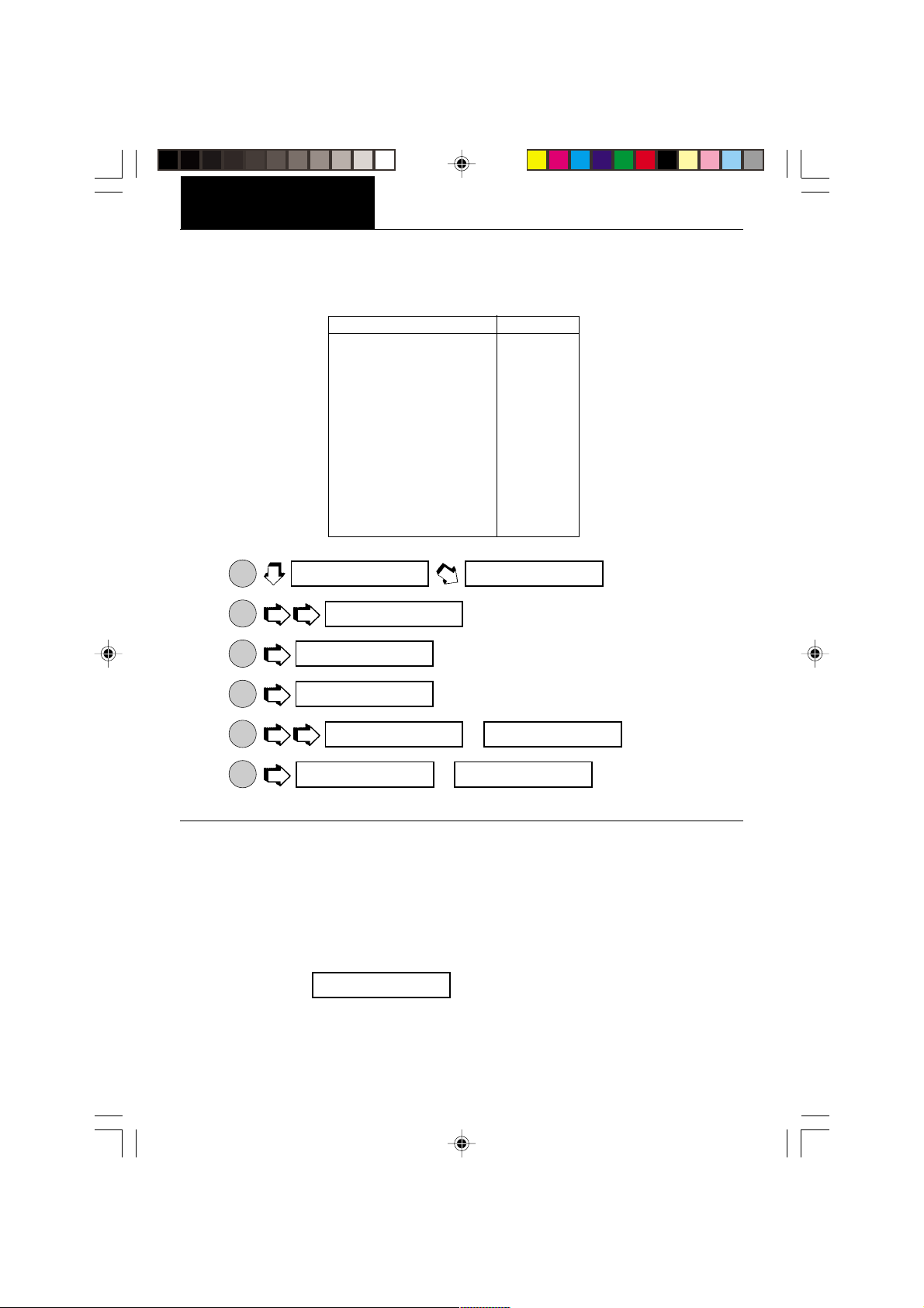
MENUS
Menu
Menu
Reset
This submenu enables you to reset all Print menu selections to the factory default settings
shown below. Reset does not appear if the menu has been locked out.
Function Default
Baud Rate br2400
Data Bits 7 data
Parity none
Stop Bits 2 stop
Auto Print OFF
Auto Print interval 1 second
Non Print Low Limit 0
Non Print High Limit 0
Stable data Only OFF
Numeric Data Only OFF
Time OFF
Date OFF
1.
2.
3.
4.
5.
6.
ON
.
TARE
MODE
.
ON
.
TARE
ON
.
TARE
MODE
or .
ON
. If is selected, the balance
TARE
signals a
^]emu cal
pR INT
ReseT
yes
yes NO
ReseT yes
long beep
and all selections reset to factory settings.
Communication
The Communication submenu contains submenus which permit the setting of: baud rates,
data bits, parity and stop bits necessary for communications to an external printer or
computer.
Access the
co^]
submenu under the Print menu.
52
Page 59
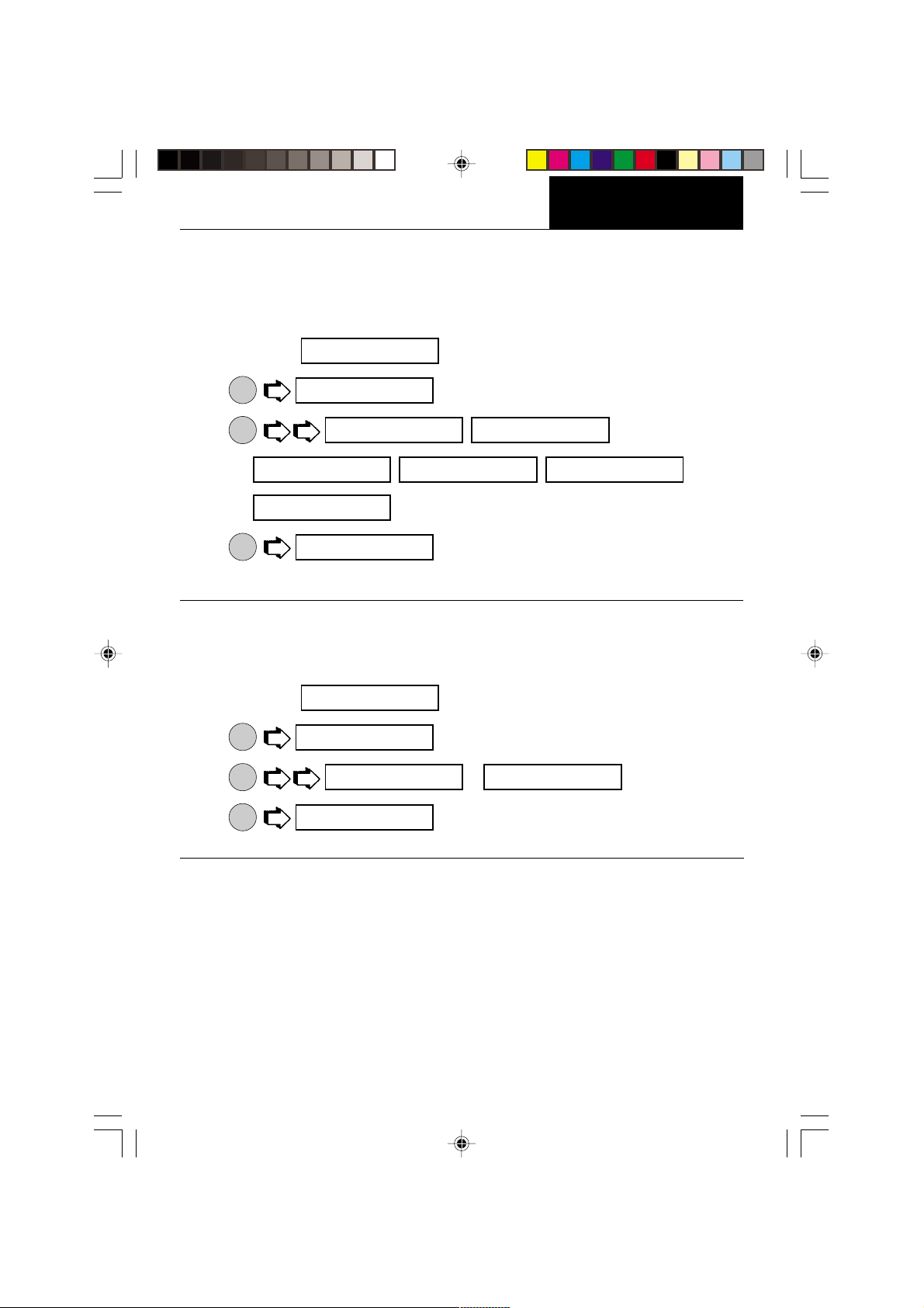
MENUS
Menu
Menu
Baud Rate
This submenu is used to select the desired baud rate. There are five available baud rates
to choose from: 300, 1200, 2400, 4800 and 9600. The default setting is 2400 baud.
To view or change the baud rate:
1. Access the submenu.
ON
2.
3.
4.
.
TARE
MODE
, ,
BR 4800 BR ·600 BR 300
BR 1200
ON
.
TARE
BaUD
BR 1200
BR 1200 BR 2400
, , ,
. Normal baud rate is 2400.
BaUD
Data Bits
To set the number of data bits to 7 or 8:
1. Access the
ON
2.
3.
.
TARE
MODE
or .
DaTa
7 DaTa
7 DaTa 8 DaTa
submenu.
ON
4.
.
TARE
DaTa
53
Page 60
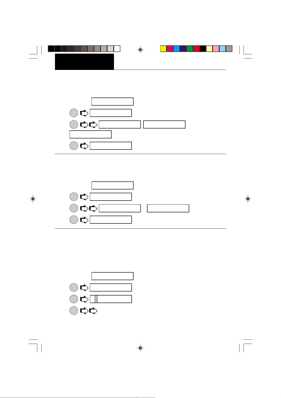
MENUS
Menu
Menu
Parity
Parity can be set to Odd, Even or None. The default setting is None. To set parity, proceed
as follows:
1. Access the submenu.
ON
2.
3.
4.
.
TARE
MODE
, ,
-oDD-
ON
.
TARE
paR ITy
NONe
NONe -e-
.
paR ITy
Stop Bits
The number of stop bits can be set to 1 or 2. The default setting is 2. To set stop bits, proceed
as follows:
1. Access the
ON
2.
3.
4.
.
TARE
MODE
or .
ON
.
TARE
sTop
2 sTop
2 sTop 1 sTop
sTop
submenu.
Good Laboratory Practice (GLP)
This submenu enables the storage of an identification number and/or a project number.
When entered into the balance, the identification number and project number are available
when printing. The reason the entries are made under the Print submenu, is that when legal
for trade operation (LFT) is enabled, the Setup submenu is locked out, leaving the Print
submenu free to make entries.
1. Access the
ON
2.
3.
4.
.
TARE
ON
first digit is flashing.
TARE
MODE
changes the value of the first digit.
9lp
iD NO
0000000
submenu.
54
Page 61
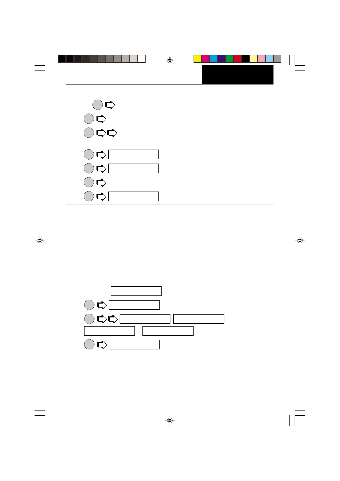
Good Laboratory Practice (GLP) (Cont.)
Menu
Menu
MENUS
NOTE:
5.
6.
MODE
allows going back to the previous digit for correction.
ON
accepts value and moves to second digit.
TARE
MODE
to change next digit.
7. Repeat steps 4 through 6 to change all digits.
8.
9.
10.
11.
ON
.
TARE
MODE
to enter project number.
ON
and repeat steps 3 through 7.
TARE
MODE
.
iD NO
pR NO
pR NO
Print Options
This submenu contains additional features which can be set and include Auto Print, Initialize
Auto Print, Stable Data only, Numeric Data only, Time, Date and Reference data and
Difference. To change any of the above listed options, enter the submenu.
Auto Print Feature
When enabled, the Auto Print feature causes the balance to automatically output display
data in one of three ways: continuously, at user specified time intervals, or upon stability.
To select one of these Auto Print methods, or to turn the feature off:
1. Access the submenu.
ON
2.
3.
4.
.
TARE
MODE
, ,
iNTeR oN sTB
ON
.
TARE
aUTOp
off
off cONT
or .
aUTOp
NOTE: If you select interval to automatically output data at user specified time intervals, the
interval is entered in the Initialize submenu which follows.
55
Page 62
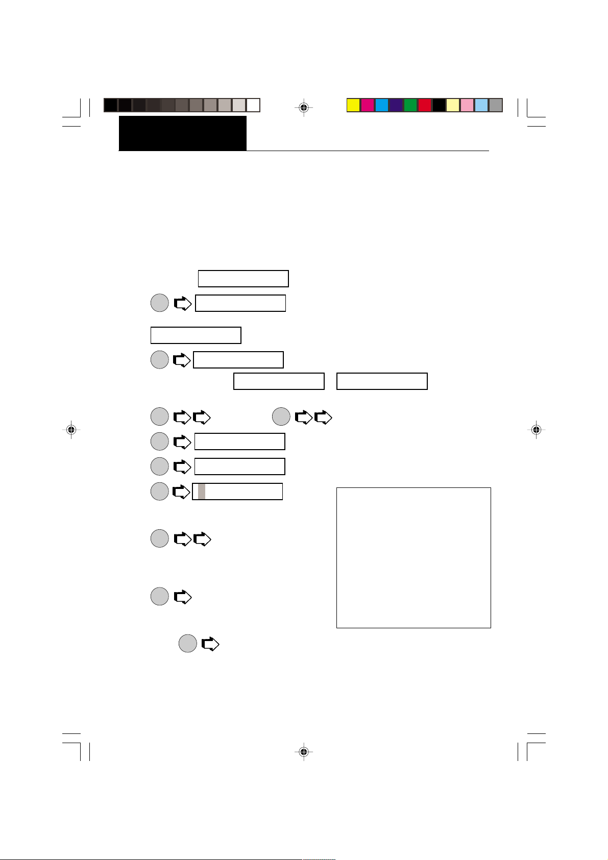
MENUS
Menu
Menu
Initialize
This submenu allows you to:
• Specify a time interval (in seconds) for automatic output.
• Exclude a range of weights from being output, or specify a range for output, by the Auto
Print feature.
It does not appear on the Print menu if Auto Print is set to OFF. Use the following procedure
to set these features:
1. Access the
ON
2.
displays if Interval was selected in the Auto Print
TARE
iN IT
iNTeR
submenu under the Print Options submenu.
submenu and you may continue with step 3. If interval was not selected,
NON-pl
ON
3.
to enter time interval for automatic data output. The
TARE
iNT 1
current interval from to (in seconds) is
is displayed. Proceed to step 7.
iNT 1 iNT 256
displayed.
MODE
4.
5.
6.
7.
to increase or
ON
.
TARE
MODE
to enter a range of non printing values.
ON
, the current
TARE
iNTeR
NON-pl
000.0000
value for the low end of the range is displayed
with the first digit flashing.
MODE
8.
to change the number, start
with the first digit (flashing). Change the value
to any number from -9 to +9. A minus sign will
light to indicate a negative value.
ON
9.
to accept it and the next digit will
TARE
begin flashing.
PRINT
to decrease the interval number.
To exclude data
WITHIN SELECTED RANGE:
SET non-PL < non-PH
Example: non-PL=7g, non-PH=11g
Values <7 OR >11 will be output.
To exclude data
OUTSIDE SELECTED RANGE:
Set non-PL > non-PH
Example: non-PL=11g, non-PH=7g
Values >7 AND <11 will be output.
10.Set all digits in the same manner. If an error is
PRINT
made,
to backup to the desired digit and change it.
56
Page 63
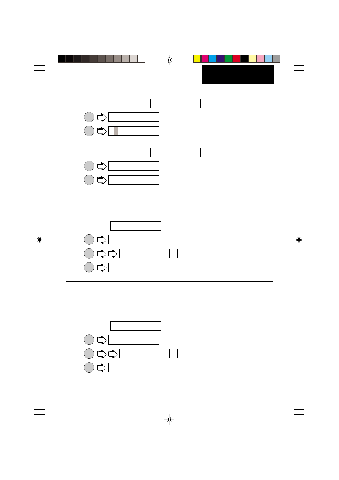
Initialize (Cont.)
Menu
Menu
MENUS
11.After the last digit is entered,
12.
13.
MODE
for the high limit.
ON
indicates current high end value.
TARE
NON-ph
0000000
NON-pl
is displayed again.
14.Repeat steps 8 through 10 to change the numbers as required.
15.After the last digit is entered,
16.
17.
MODE
.
ON
.
TARE
eND
iN IT
NON-ph
displayed again.
Print Stable Data Only
When enabled, this feature permits only stable display data to be output. To set the feature
ON or OFF, proceed as follows:
1. Access the
ON
2.
3.
4.
.
TARE
MODE
or .
ON
.
TARE
sTaBle
off
off oN
sTaBle
submenu under the Print Options menu.
Print Numeric Data Only
This submenu is used to select numeric data only, or full display data for RS232 output. Set
this feature ON to output numeric display data only, or OFF to output full display data as
follows:
1. Access the
ON
2.
3.
4.
.
TARE
MODE
or .
ON
.
TARE
NU
off
off oN
NU
submenu under the Print Options menu.
57
Page 64
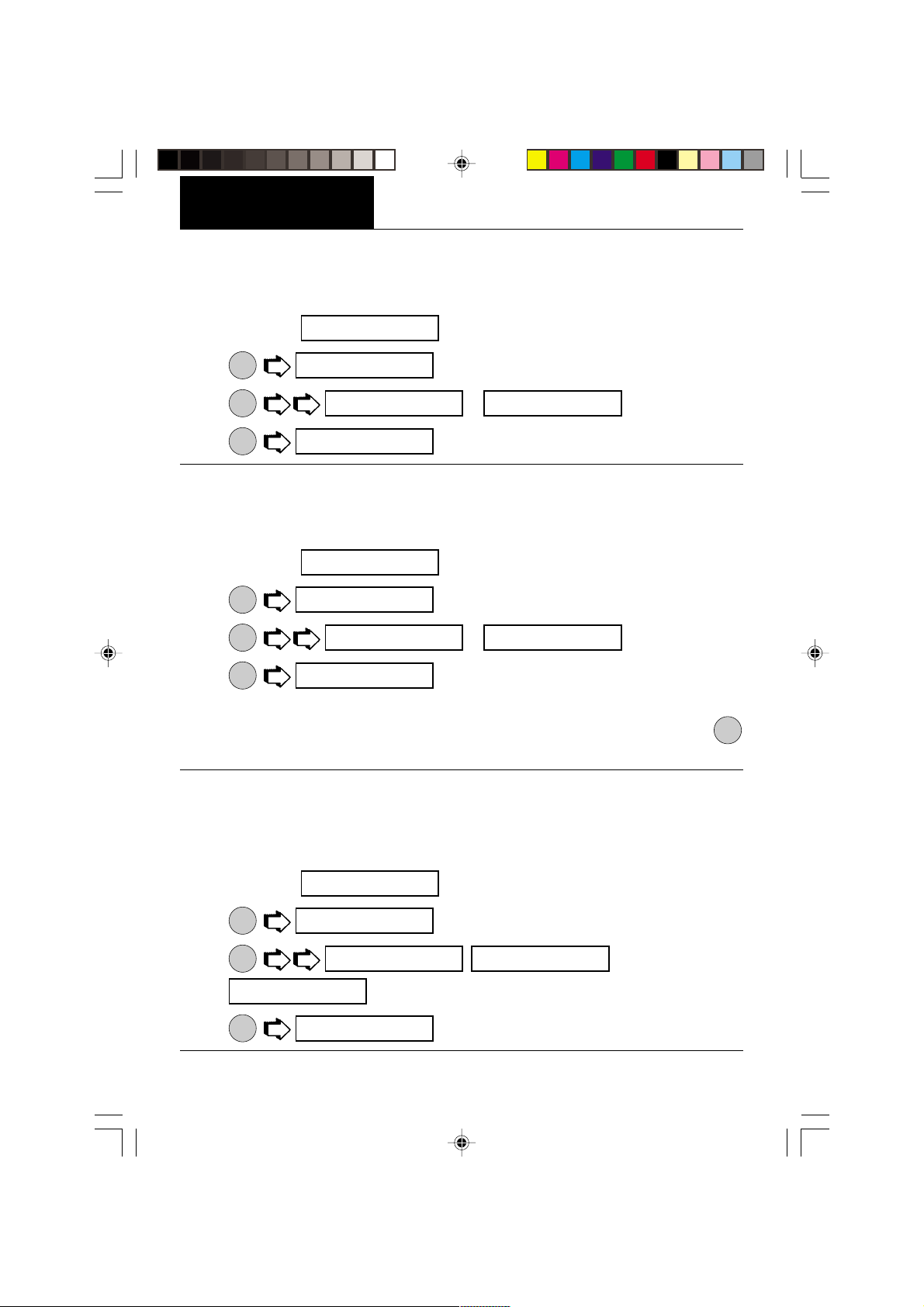
MENUS
Menu
Menu
Time
When the Time function is set ON, allows the balance to output the current time to the printer.
To set the Time feature ON or OFF, proceed as follows:
1. Access the
ON
2.
3.
4.
.
TARE
MODE
or .
ON
.
TARE
T I^]e
off
off oN
T I^]e
submenu under the Print Options menu
Date
When the Date function is set ON, allows the balance to output the current date to the printer.
To set the Date feature ON or OFF, proceed as follows:
1. Access the
ON
2.
3.
4.
.
TARE
MODE
or .
ON
.
TARE
DaTe
off
off oN
DaTe
submenu under the Print Options menu
NOTE: With Print Time or Date set to ON, if either current Time or Date has not been set in
Setup menu, “Set Time/Date !” is sent through the RS232 Interface with each press of
PRINT
button.
Reference
When the Reference function is set ON, prints the value of weight used as a reference in
either Check Weighing, Fill Guide, Percent and Parts Counting modes. When set to Current,
the printer prints the current reference immedediately.
1. Access the
ON
2.
3.
4.
.
TARE
MODE
, or
cURReNT
ON
.
TARE
Ref
off
off oN
.
Ref
submenu under the Print Options menu
58
Page 65
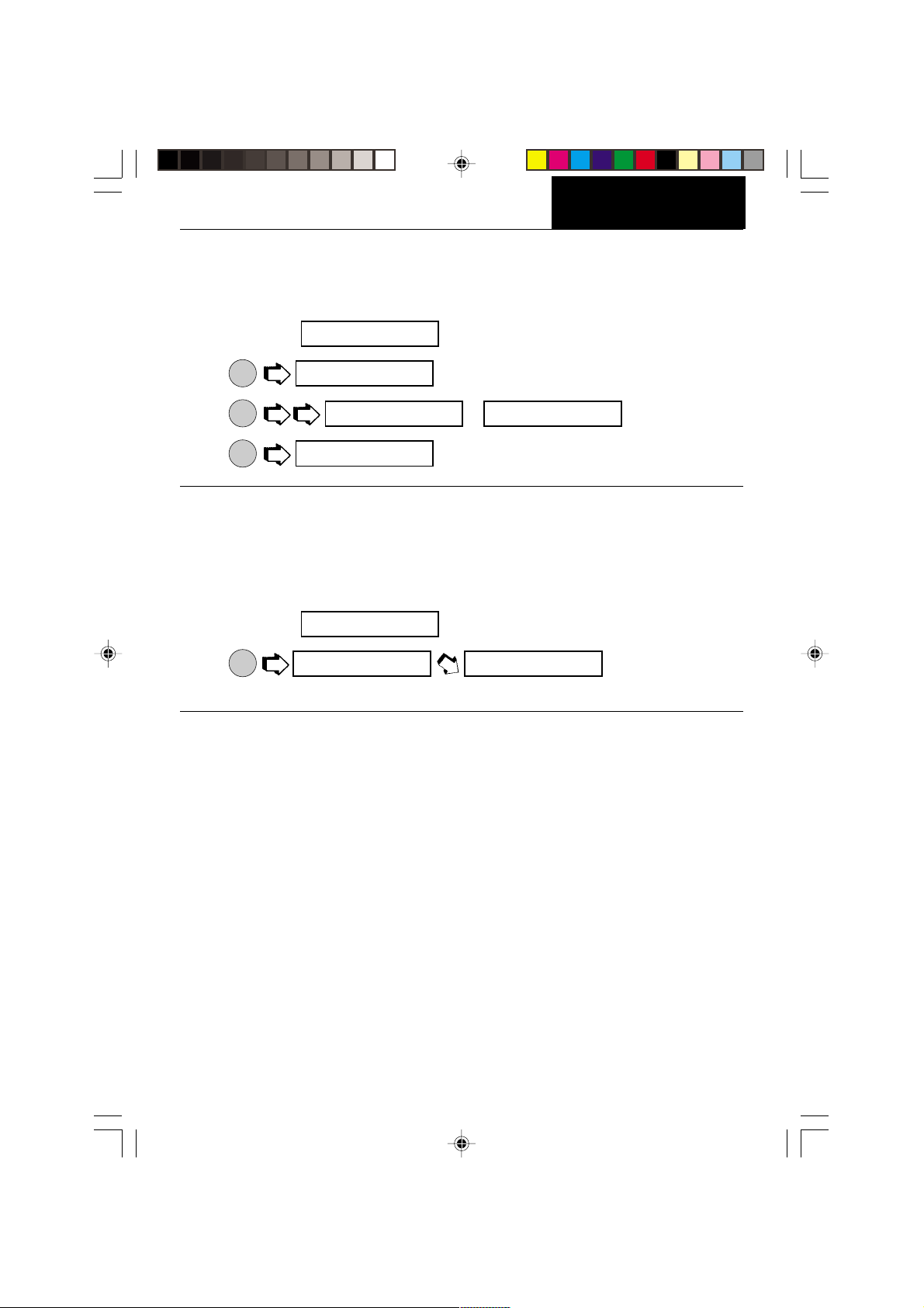
MENUS
Menu
Menu
Difference
Difference data is only output to the printer when Check Weighing or Fill Guide
selected.
TM
mode was
1. Access the
ON
2.
3.
4.
.
TARE
MODE
or .
ON
.
TARE
D Iff
off
off oN
D Iff
submenu under the Print Options menu
List
This submenu can be used to output a listing of current menu settings via the RS232
interface. When selected, all menu settings for the User, Setup and Print menus will be
output either to an external printer or computer. To use this feature, your balance must be
connected to a computer or printer.
1. Access the
ON
2.
The display indicates a
TARE
l IsT
l IsT . . . . . . .
series of dots traveling right to left when the balance is sending information.
submenu under the Setup or Print menus.
59
Page 66
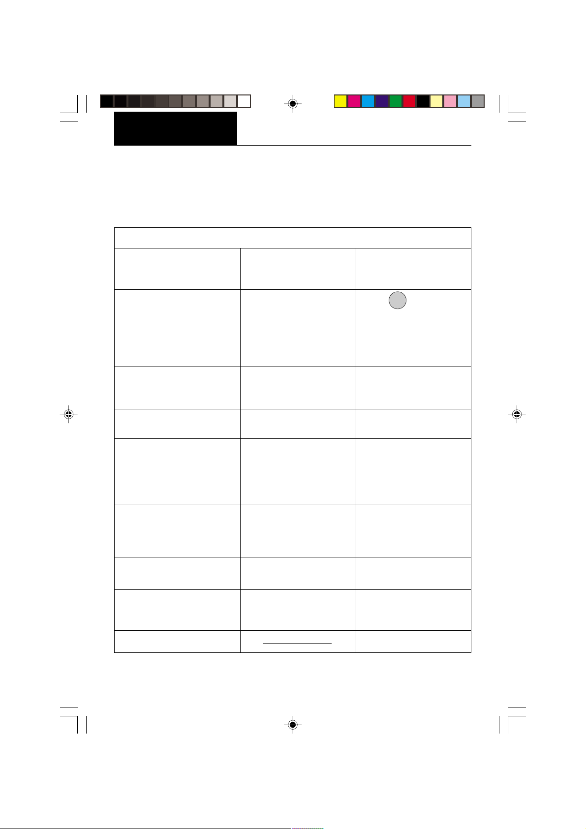
MAINTENANCE
Menu
Menu
CARE AND MAINTENANCE
To keep the balance operating properly, the housing and platform should be kept clean and
free from foreign material. If necessary, a cloth dampened with a mild detergent may be
used. Keep calibration masses in a safe dry place.
TROUBLESHOOTING
SYMPTOM
Unit will not turn on.
Incorrect weight reading.
Cannot display weight in
desired unit or cannot access
desired weighing mode.
Unable to store menu
settings/changes.
RS232 interface not working.
Random segments displayed
or display
locks up.
PROBABLE CAUSE(S)
Power cord not plugged in
or properly connected to
balance.
Balance was not re-zeroed
before weighing.
Balance not properly
calibrated.
Desired unit/mode not
set to ON in Unit Selection
of Setup menu.
End not being used to exit
menus.
Print menu settings not
properly set up.
Cable connections.
Microprocessor locks up.
REMEDY
Check power cord
connections.
Press
on the pan, then weigh
item.
Recalibrate correctly.
See Unit Selection section
of Setup menu.
You MUST use End to exit
menus and save settings.
Verify interface settings in
Print menu correspond to
those of peripheral device.
Check cable connections.
Turn power off, then turn
on again. If condition
persists, unit must be
serviced.
ON
with no weight
TARE
Unable to change
settings.
Unstable readings.
Error message display.
Lock set ON.
(LFT set ON)
Vibration on table surface.
60
Set Lock switch to OFF.
Place balance on a stable
surface or change
averaging level.
See Error Codes list.
Page 67
MAINTENANCE
Menu
Menu
Error Codes List
The following list describes the various error codes and which can appear on the display and
the suggested remedy.
Data Errors
0.0 Internal data errors. If error persists, the balance must be serviced.
1.0 Internal data errors. If error persists, the balance must be serviced.
Tare Errors
2.0 Illegal tare operation or balance is unable to stabilize within time limit after taring.
Environment is too hostile or balance needs recalibration.
Calibration Errors
3.0 Incorrect or no calibration weight used for User calibration. Recalibrate with correct
weights.
5.0 Auto calibration failed. Environment is to hostile, recalibrate the balance.
RS232 Errors
4.4 RS232 buffer is full (if installed). May occur if no printer or computer is connected to
the interface. To clear buffer, turn balance off or enter Print menu and select END.
4.5 Function is disabled by the Lock switch.
User Errors
7.0 User entry out of range (custom factor, non-pH, non-pL, etc...)
7.1 Bad percent (%) mode, sample too low.
7.2 Number outside of display capacity.
Over-Under Load Errors
8.0 Hardware error causing an internal weight signal which is too low. Check if platform
or platform support is off. If not, the balance must be serviced.
8.2 Internal power on error. Turn the power off, then turn it back on.
8.3 Hardware error caused by an internal weight signal which is too high. Check load on
the platform which may be excessive. If error persists, the balance must be serviced.
61
Page 68
MAINTENANCE
Menu
Menu
Error Codes List (Cont.)
System Errors
5.1 thrrough 5.9
System errors. Turn the power off, then turn it back on. If error persists, have the balance
serviced.
Checksum Errors
9.7 Invalid setup data checksum. Check Setup, User, and Print menus settings. If
possible, try to enter menus and exit using END to restore menu settings. May
be caused by a faulty component, or in rare cases, a severe static charge. If
error persists, balance must be serviced.
If your balance displays ERR 9.7 briefly at switch-on, please follow the
procedure below:
Switch balance on:
1.
2.
3.
4.
5.
6.
7.
8.
9.
10.
ON
TARE
MODE
ON
TARE
ON
TARE
ON
TARE
PRINT
ON
TARE
MODE
ON
TARE
ON
TARE
eND usR
^]emu
useR
ReseT
yes
ReseT
useR
seTup
ReseT
yes
11.
12.
13.
14.
15.
16.
17.
18.
19.
20.
ON
TARE
PRINT
ON
TARE
MODE
ON
TARE
ON
TARE
ON
TARE
PRINT
ON
TARE
MODE
ReseT
eND
seTup
pR INT
ReseT
yes
ReseT
eND
pR INT
eND
62
21.
ON
TARE
Page 69
MAINTENANCE
Menu
Menu
SERVICE INFORMATION
If the Troubleshooting section does not resolve or describe your problem, you will need to
contact an authorized Ohaus Service Agent. For Service assistance in the United States,
please call Ohaus Corporation toll-free at (800) 526-0659. An Ohaus Product Service
Specialist will be available to help you.
If you have to dispose of the instrument, contact your OHAUS agency.
REPLACEMENT PARTS
OHAUS
Part No.
Power Cords:
U.S. 120 V∼ 6569-00
European 230 V∼ 76212-00
European 240 V∼ 76448-00
Pan (AP110, AP210 and AP250D models) 9773-00
Pan (AP310 models) 9773-01
Pan Shield 9773-02
Pan Ring 9773-03
Leveling Foot 9773-04
In-Service Cover 9773-78
Fuse (T 160 mA/250 V for all models) 90167-42
ACCESSORIES
Anti-Theft Device 77401-00
Density Determination Kit 77402-00
Storage Cover 9773-79
Calibration Masses - ASTM Class 1 Tolerance:
100 g 49015-11
200 g 49025-11
63
Page 70
MAINTENANCE
Menu
Menu
SPECIFICATIONS
MODEL AP110 AP210 AP310 AP250D
Capacity (g) 110 210 310 52/210
Readability (mg) 0.1 0.01/0.1
Weighing modes g, oz, ct, dwt, (3) taels, oz t, gn, mommes,
1 custom unit, parts counting, percent weighing,
Repeatability (Std. dev.) (mg) 0.1 0.2 0.02/0.1
Linearity (mg) ±0.2 ±0.5 ±0.03/0.2
Tare range To capacity by subtraction
Stabilization time (sec) 4 8 12/5
Sensitivity drift (10 - 30 °C) ±2 ppm/ °C
Operating temperature range 50° to 104°F/10° to 40°C
Relative humidity max. 80 %
Installation category II
Pollution degree 2
Calibration Motorized internal and manual external
Internal calibration weights Stainless steel - measured to ±0.1 mg at an
air density of 1.2 mg/cm
on virtual mass with density 8.0 g/cm
Power requirements 100-120 V∼, 110 mA, 50/60Hz
220-240 V∼, 55 mA, 50/60Hz
Display (in/cm) Vacuum fluorescent (0.5/1.3 high)
Pan size (in/cm) 3.5/9
Free height above pan (in/cm) 9.5/24
Dimensions 7.7 x 12.2 x 15.7
(WxHxD) (in/cm) 19.5 x 31 x 40
Net weight (lb/kg) 22.5/10.2
64
3
3
Page 71
Ohaus Corporation, 19A Chapin Road, Pine Brook, New Jersey, 07058-9878, USA
Menu
Menu
Declaration of Conformity We, Ohaus Corporation, declare under our sole responsibility that the balance
models listed below marked with “CE” - are in conformity with the directives and standards mentioned.
Konformitätserkärung Wir, die Ohaus Corporation, erklären in alleiniger Verantwortung, dass die unten-
stehenden Waagentypen, gekennzeichnet mit “CE” - mit den genannten Richtlinien und Normen überein-
stimmen.
Déclaration de conformité Nous, Ohaus Corporation, déclarons sous notre seule responsabilité, que les
types de balance ci-dessous cité - munis de la mention “CE” - sont conformes aux directives et aux normes
mentionnées ci-après.
Declaración de Conformidad Nosotros, Ohaus Corporation, declaramos bajo responsabilidad exclusiva
que los modelos de balanzas indicados a continuación - con el distintivo “CE” - están conformes con las
directivas y normas citadas.
Dichiarazione di conformità
Noi, Ohaus Corporation, U.S.A, dichiariamo sotto nostra unica responsabilità,
che i tipi di bilance specificati di seguito - contrassegnati con la marcatura “CE” - sono conformi alle direttive
e norme citate.
Balance Type/Waagentyp/Type de balance/Modelo de balanza/Tipo di biliancia AP
Marked with: Directive Standard
gekennzeichnet mit: Richtlinie Norm
munis de la mention: Directive Norme
con el distintivo: Directiva Norma
contrassegnati con la marcatura: Direttiva Norma
EEC 73/23 & SR734.26 EN61010-1:1993+A2:1995, CAN/CSA-C22.2 No. 1010.1-92
Low Voltage UL Std. No. 3101-1 Safety requirements
EWG 73/23 & SR734.26 EN61010-1:1993+A2:1995, CAN/CSA-C22.2 No. 1010.1-92
Niederspannung UL Std. No. 3101-1 Sicherheitsbestimmungen
CEE 73/23 & SR734.26 EN61010-1:1993+A2:1995, CAN/CSA-C22.2 No. 1010.1-92
Basse tension UL Std. No. 3101-1 Règles de sécurité
Year of attachment Baja tensión UL Std. No. 3101-1 Disposiciones sobre seguridad
of the CE mark CEE 73/23 & SR734.26 EN61010-1:1993+A2:1995, CAN/CSA-C22.2 No. 1010.1-92
Jahr der ersten Bassa tensione UL Std. No. 3101-1 Norme di sicurezza
Eichung
Année de EEC 89/336 & SR 734.5 EN61326-1:1997 (class B) +A1:1998
la premère Electromagnetic compatibility FCC, Part 15, class A, AS/NZS4251.1 Emissions
vérification EN61326-1:1997+A1:1998, AS/NZS4252.1 Immunity
Año de la primera EWG 89/336 & SR 734.5 EN61000-4-11:1994 Disturbance
verificación Elektromagnetische Verträglichkeit EN61326-1:1997 (class B) +A1:1998
annodella prima FCC, Part 15, class A, AS/NZS4251.1 Funkstörungen
verifica CEE 89/336 & SR 734.5 EN61326-1:1997+A1:1998, AS/NZS4252.1 Immunität
01
CEE 73/23 & SR734.26 EN61010-1:1993+A2:1995, CAN/CSA-C22.2 No. 1010.1-92
Compatibilité électromagnétique EN61000-4-11:1994 Rückwirkung
CEE 89/336 & SR 734.5 FCC, Part 15, class A, AS/NZS4251.1 Emissions parasites
Compatibilidad electromagnética EN61326-1:1997+A1:1998, AS/NZS4252.1 Immunité
CEE 89/336 & SR 734.5 EN61326-1:1997 (class B) +A1:1998
Compatibilità elettromagnetica FCC, Part 15, class A, AS/NZS4251.1 Radiointerferencias
EEC 90/384 NAWI EN45501 Non Automatic Weighing Instruments
EWG 90/384 FNSW EN45501 für nicht selbsttätige Waagen
CEE 90/384 BFNA EN45501 balances à fonctionnement non automatique
CEE 90/384 PBNA EN45501 para balanzas no automátäcas
T2110
CEE 90/384 BFNA EN45501 per bilance a funzionamento non automatics
EN61326-1:1997 (class B) +A1:1998
EN61000-4-11:1994 Perturbation
EN61326-1:1997+A1:1998, AS/NZS4252.1 Inmunidad
EN61000-4-11:1994 Perturbacion
EN61326-1:1997 (class B) +A1:1998
FCC, Part 15, class A, AS/NZS4251.1 Radiointerferenze
EN61326-1:1997+A1:1998, AS/NZS4252.1 Immunità
EN61000-4-11:1994 Perturbazioni
65
Page 72
ISO 9001 Certificate for Ohaus Corporation. Ohaus Corporation, USA, was examined and evaluated in 1994 by the
Menu
Menu
Bureau Veritas Quality International, BVQI, and was awarded the ISO 9001 certificate. This certifies that Ohaus
Corporation, USA, has a quality system that conforms with the international standards for quality management and quality
assurance (ISO 9000 series). Repeat audits are carried out by BVQI at intervals to check that the quality system is operated
in the proper manner.
ISO 9001-Zertifikat für Ohaus Corporation. Die Firma Ohaus Corporation, USA, wurde 1994 durch das Bureau Veritas
Quality International BVQI geprüft, und erhielt das ISO 9001 Zertifikat. Dieses bescheinigt, dass Ohaus Corporation, USA
über ein Qualitätssystem verfügt, welches den internationalen Normen für Qualitätsmanagement und Qualitátssicherung
(ISO 9000er-Reihe) entspricht. Anlässlich von Wiederhol-Audits durch das BVQI wird periodisch überprüft, ob das
Qualitätssystem zweckmässig gehandhabt wird.
Certificat ISO 9001 pour Ohaus Corporation. La société Ohaus Corporation, USA, a été contrôlée en 1994 par Bureau
Veritas Quality International BVQI et a obtenu le certificat, degré ISO 9001. Celui-ci atteste que Ohaus Corporation, USA,
dispose d’un système qualité correspondant aux normes internationales pour la gestion de la qualité et pour I’assurance
qualité (degré ISO 9000). Des audits réguliers effectués par la BVQI vérifient si le système qualité est appliqué de facon
appropriée.
Certificado ISO 9001 para Ohaus Corporation. La firma Ohaus Corporation, USA, ha sido inspeccionada por la Bureau
Veritas Quality International (BVQI) y ha obtenido el certificado ISO 9001. Esto acredita que Ohaus Corporation, USA,
dispone de un sistema de calidad que cumple las normas internacionales para gestión y garantfa de calidad (ISO serie
9000). Con ocasión de las inspecciones de repetibilidad por parte de la BVQI, se comprueba periódicamente si el sistema
de calidad se manipula de forma correcta.
Certificato ISO 9001 per la Ohaus Corporation. ll sistema di garanzia della qualità della Società Ohaus Corporation,
USA è certificato ISO 9001 sin dal 1994 dall Bureau Veritas Quality International BVQI, e così fomice la dimostrazione che
il suo sistema die Garanzia Qualità soddisfa i massimi requisite. ll sistema della garanzia della qualità Ohaus Corporation
viene verificato periodicamente dall BVQI, dando cosi evidenza di.
66
Page 73
Notice
Menu
Menu
Certified scales,scales used for legal applications have the general type designation E...5 / V ...5
and EU type Approval (T2110). The year of the initial verification is shown next to the CE mark.
Such scales are verified in the factory and carry the “M” mark on the actual scale and the
packaging. The year of the initial verification is shown next to the CE mark. If the letter M is
shown against a solid background, the scale may be put into operation immediately. Should the
background be partitioned and hatched, the scale must be verified at its place of use by the
certified Ohaus service. If national regulations limit the duration of the validity of the verification
certificate in individual countries, the end user of such a scale is personally responsible for
arranging the repeat verification in good time.
Hinweise
Geeichte/eichpflichtige Waagen tragen die allgemeine T ypenbezeichnung E... 5 / V...5. Für sie
liegt eine EU Bauartzulassung vor (T2110). Das Jahr der ersten Eichung ist neben dem CE
Zeichen aufgeführt. Solche Waagen sind ab Werk geeicht und tragen die Kennzeichnung “M”
auf dem Gerät selbst und auf der Verpackung. Erscheint der Buchstabe M auf vollem Grund,
darf die Waage sofort in Betrieb genommen werden. Ist der Grund geteilt und schraffiert, muss
die Waage am Verwendungsort durch den zertifizierten Ohaus Service ortsgeeicht werden.
Sofern gemäss den nationalen Vorschriften in den einzelnen Staaten die Güitigkeitsdauer der
Eichung beschränkt ist, ist der Betreiber einer soichen Waage für die rechtzeitige Nacheichung
selbst verantwortlich.
Remarques
Les balances vérifiées/admissibles à la vérification portent la désignation de modèle générale
E...5 / V ... 5. Elles font l’objet d’une approbation de modèle UE (T21 10). L’année de la vérification
primitive est indiquée à côté de la marque CE. Ces balances sont vérifidées d’origine et portent
la marque “M” sur I’appareil lui-même et sur l’emballage, Si la lettre M apparaît sur un fond
totalement vert, la balance peut être mise en service immédiatement. Si le fond est divisé et
hachuré, la balance doit être vérifiée sur le lieu d’ustilisation par le service après-vente Ohaus
certifié. Dans les pays où la durée de validité de la vérification est limitée par des prescriptions
nationales, l’utilisateur est lui-même responsable de la vérification ultérieure d’une telle balance
en temps voulu.
Notas
Las balanzas verificadas/verificables llevan la designatión general E...5 / V ...5 y cuentan con
una aprobación de modelo UE (T2110). EL año de la primera verficación está indicado al lado
del distintivo CE. Estas balanzas están verificadas en fábrica y Ilevan la designatión “M” sobre
el propio aparato y sobre el embalaje. Cuando la letra M aparece sobre fondo sólido, la balanza
se puede poner inmediatamente en funcionamiento. Si el fondo está dividido y rayado, la balanza
ha de ser verificada en el lugar de uso por el sevicio técnico Ohaus certificado. Si la duración de
la validez de la verificación está limitada de acuerdo con las normas de los distintos países, el
propio usuario de tal balanza es responsable de la verificación posterior a su debido tiempo.
67
Page 74
Avvertenza
Menu
Menu
Le bilance approvate hanno la denominazione del modello E... 5 / V ...5. Per esse esiste
un’appprovazione CE del tipo (T2110). L’anno delia prima verifica è indicato a fianco della
marcatura CE. I tipi marcati con un contrassegno “M” su sfondo verde pieno possono essere
impiegati da subito. I tipi marcati con ii contrassegno “M” su sfondo nero/barrato diagonalmente
dovranno essere verificati sul luogo d’installazione da parte d’un tecnico autorizzato dal Servizio
Assistenza Ohaus o ispettore dell’Ufficio Metrico. Queste bilance sono state verificate in fabbrica
e recano il contrassegno “M” sull’apparecchio stesso, e sull’imballo. É obbligo dell’untente
denunciare la detenzione dello strumento all’ufficio metrico competente per territorio e sottoporio
alia prescritta verifica periodica come da disposizioni ministeriali.
68
Page 75
LIMITED WARRANTY
Menu
Menu
Ohaus products are warranted against defects in materials and workmanship from the date
of delivery through the duration of the warranty period. During the warranty period Ohaus will
repair, or, at its option, replace any component(s) that proves to be defective at no charge,
provided that the product is returned, freight prepaid, to Ohaus.
This warranty does not apply if the product has been damaged by accident or misuse,
exposed to radioactive or corrosive materials, has foreign material penetrating to the inside
of the product, or as a result of service or modification by other than Ohaus. The warranty
period shall begin at the date of installation, or three months from shipment to the buyer,
whichever occurs first. A properly completed Warranty Registration Card must be received
by Ohaus within 30 days from date of purchase to initiate coverage under the warranty. No
other express or implied warranty is given by Ohaus Corporation. Ohaus Corporation shall
not be liable for any consequential damages.
As warranty legislation differs from state to state and country to country, please contact
Ohaus or your local Ohaus dealer for further details.
Page 76
Ohaus Corporation OHAUS UK Ltd
Menu
Menu
19A Chapin Road, 64 Boston Road
Pine Brook, NJ 07058-9878, USA Beaumont Leys
Tel: (973) 377-9000, Leicester LE4 1AW
Fax: (973) 593-0359 England
With offices worldwide.
www.ohaus.com
© Ohaus Corporation 2001, all rights reserved.
709101E 0102/2.12
 Loading...