

Ofna Racing X2 TRUGGY Instruction Manual

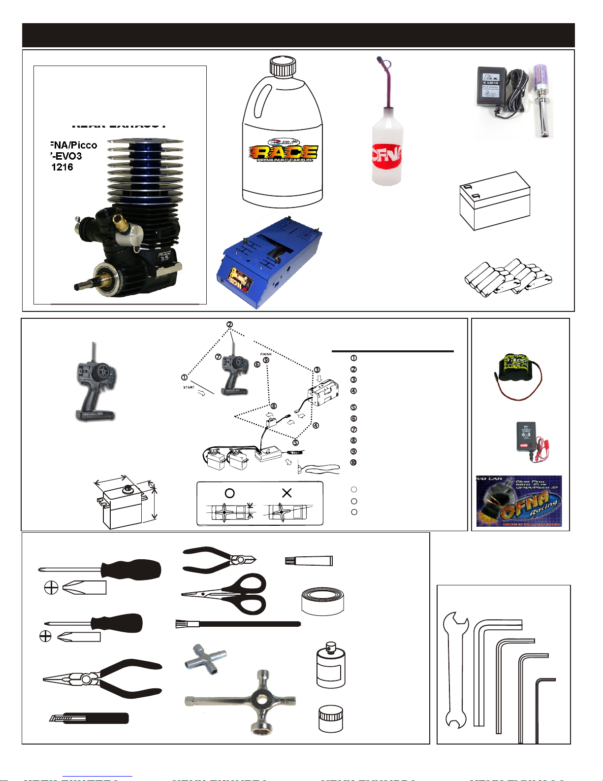
THINGS REQUIRED FOR OPERATION
OPTION PART
3.5 cc (21 Class) ENGINE
REAR EXHAUST
OPTION THINGS NEED BESIDES THE KIT
OFNA/Picco
P7-EVO3
#51216
RADIO CONTROL UNIT
Note: Carefully read the instruction manual of your
2 channel radio controller before using.
SUITABLE SERVO SIZE
4 m
- 1m
m
6m
3
15mm - 21mm
29mm - 42mm
Bottle’s with spout
# 10160 - large 500cc
# 10161 - large 500 ccAuto Stop
# 10162 - small 250cc
# 10164 - CNC spout 500CC
# 10167 - CNC spout 800CC
Off-Road Starter Box, 12V motor
# 10250 - 1/8 scale Starter Box
# 10253 - 1/8 scale Starter Box w/ Panel
Off-Road Starter Box, two 550 motors
# 10248 - 1/8 scale Starter Box
# 10249 - 1/8 scale Starter Box,RTR
Optional Parts
# 92571 - Power Panel Glow Heater
# 92572 - Cable for Glow Plug
Radio must be set at neutral position
before installing in the kit.
SEQUENCE TO SET NEUTRAL
Install AA batteries in Radio.
Extend the antenna.(Transmitter)
Install batteries into Car receiver .
After installing the battery, connect the
battery box.
Extend the antenna. (Receiver)
Set the trim-lever at center.
Turn on the switch. (Transmitter)
Turn on the switch. (Receiver)
Make sure the servos are in command.
When the operation stick is in neutral,
servo horns must be in neutral as well.
*Adjustment can be made by re installing the servo horn.
1111
Turn off the switch. (Receiver)
Turn off the switch. (Transmitter)
12
13
Retract the antenna. (Transmitter)
Glow Plug Heat with Battery & Charger
# 10227....$$19.95
(please note OFNA Glow Heats available)
12V Battery for Starter Box
(must have)
AA Batteries ( 12 pcs ) for radio
More Optional Parts . . .
#10201
1700 NimH Battery Hump
Pack .. $34.95
# 10214 NiMh Battery Pack
Charger.. $7.95
# 51007 or 08 OFNA/Picoo
Glow Plug .. $13.95
TOOLS NOT INCLUDED IN KIT
Cutter
Phillips Type Screw Drivers ( L )
Curved Scissors
Brush
Phillips Type Screw Drivers ( S )
Needle Nose Pliers
Glow Plug & 17MM Cross Wrench
Knife
#10801 $6.95
Cross Wrench
#17109 $3.95
Instant Cement
Masking Tape
Paints
Grease
INCLUDED WITH KIT
7mm and 5.5mm
Hex Wrench
5mm
Hex Wrench
3mm
Hex Wrench
2.5mm
Hex Wrench
1.5mm
Hex Wrench
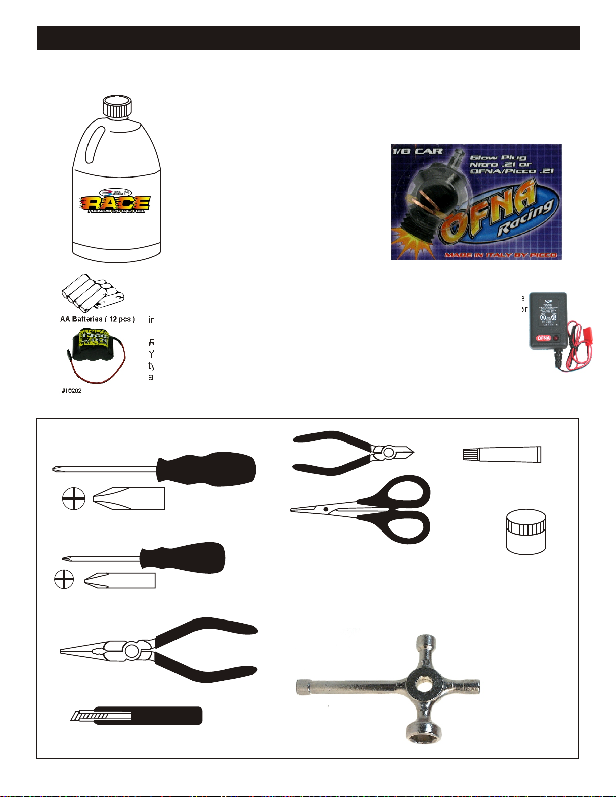
RTR KITS - REQUIRED FOR OPERATION
THINGS NEEDED
AA Batteries ( 12 pcs )
#10202
1700 Ni-Mh Hump Pack,
You will need to buy a few items to start the engine and run the car.
• Use 20% nitro CAR fuel. Do not use airplane or heli fuels, they will
over heat the engine.
• Buy LONG glow plugs, like OFNA/PICCO Plug (#51007 or 51008).
Use plugs WITHOUT idle bar. Do NOT use plugs, like the MC-59 or
OS-8
In your box you will find..
• #10163 - Bottle, spout top
• #10219 - Red “D” size glow heater
You need to get batteries for the radio transmitter and the car receiver packs.
• Radio TX needs (8) eight AA batteries.
• Car needs (4) four AA Alkaline., Alkaline type batteries will work, but braking will be
reduced and 30 minute life. The best for car, is to use a 5 cell hump receiver pack for
increased voltage and longer life..
Recommended Option:
You may want to upgrade the car battery pack to a Ni-Cad or Ni-Mh 5 cell
type(600AE). This will give more run time. OFNA #10202 1700Ni-Mh Hump Pack
and Ni-Mh Battery Charger #10214
10214
Over-nite
Charger
TOOLS NOT INCLUDED IN KIT,
BUT NEEDED TO MAINTAIN YOUR CAR.
Phillips Type Screw Drivers ( L )
Phillips Type Screw Drivers ( S )
Needle Nose Pliers
Knife
Instant Cement
Cutter
Curved Scissors
#91009 $5.95
Grease
Cross Wrench
#17109 $3.95
Glow Plug & 17MM Cross Wrench
#10801 $6.95

MUST READ THIS BEFORE RUNNING
Running a nitro kit is fun and easy, but to make this a safe • Clean oil and dirt from chassis with a degreaser like
and good experience you must observe a few rules. This
kit is extremely fast, easily over 40MPH, and can seriously
injure someone if you are not careful.
Where to run car?
• Any running area you choose must be dry. Do not run
car near any water or wet dirt.
• Do not run on public streets. It is very easy to have the
car run over or damaged by hitting the curb.
• Do not operate car in tight confined places. The car is
very fast and will easily hit something.
• Do not run near people or animals.
and will too easily hit someone.
• Due to noise, you will want to consider the surrounding
area when operating the car.
• Do not operate the car at night. You will not be able to
drive it without hitting something.
• Do not operate the car indoors. Engine exhaust is not
healthy.
Glow Fuel
• Glow fuel is poisonous!
• Glow fuel is flammable!
• Do not leave in fuel bottle with lid off at any time. fuel label for additional precautions.
• Do not use any fuel other than glow fuel in this engine.
First Time Starting the Engine
Caution! When starting engine make sure the following is
observed. • Always turn off the car BEFORE turning off radio.
• Set engine Master needle to 3 turns (rich setting)
• Do not do this alone, get an experienced friend to help at • DAMAGE DUE CAR RUN AWAY IS NOT A WARRANTY
first. ISSUE.
• Fill fuel tank, try not to spill fuel. Do not spill fuel on
receiver
• Hold car off the ground, so it will not runaway when first
started
• Turn on Radio and check the linkage before starting
engine.
• Turn on car receiver battery switch.
• Always have an air filter on the carburetor to keep dirt
out of engine.
Engine Break-in
• See Engine Page.
The car is very fast
Simple Green.
Precautions
• This kit is not a toy. Always run car with a second
person as a spotter and pitman.
• Hot Parts - The pipe, manifold, engine and head are very
hot and will cause burns.
• Rotating Parts - Keep hands away from the drive train,
wheels, and engine when engine is running.
• Radio - Check batteries life before running the car. If
radio does not have full control of the car with steering
and/or throttle/brake do not run until corrected. Failure to
correct this will result in possible injury and damage to the
car or property.
• Glow fuel - Do not leave the glow fuel unattended with
the lid off. Fuel contains Methanol and Nitro Methane
both are flammable and poisonous.
•Store fuel in cool ventilated location. Refer to the glow
• Car Fuel tank - Never store fuel in car tank, it will ruin the
engine if left in tank.
IF YOU DO NOT BREAK-IN ENGINE
CORRECTLY, MAINLY AT LOW RPM,
YOU WILL BREAK THE CONNECTING
ROD!
FAILURE TO NOT READ AND
FOLLOW BREAK-IN ENGINE
Emergency Stopping Engine When Running
• Remove air filter and cover carb. intake.
• Squeeze fuel line and hold until engine stops.
• With a rag, cover exhaust outlet.
Storing Car After Running
• Remove fuel from tank and fuel lines
• Turn off radio in car
• Put a few drops of after run in engine to keep it from
rusting.
INSTRUCTIONS WILL VOID
WARRANTY!
CHECK RADIO SETTING,
LINKAGE BEFORE STARTING.
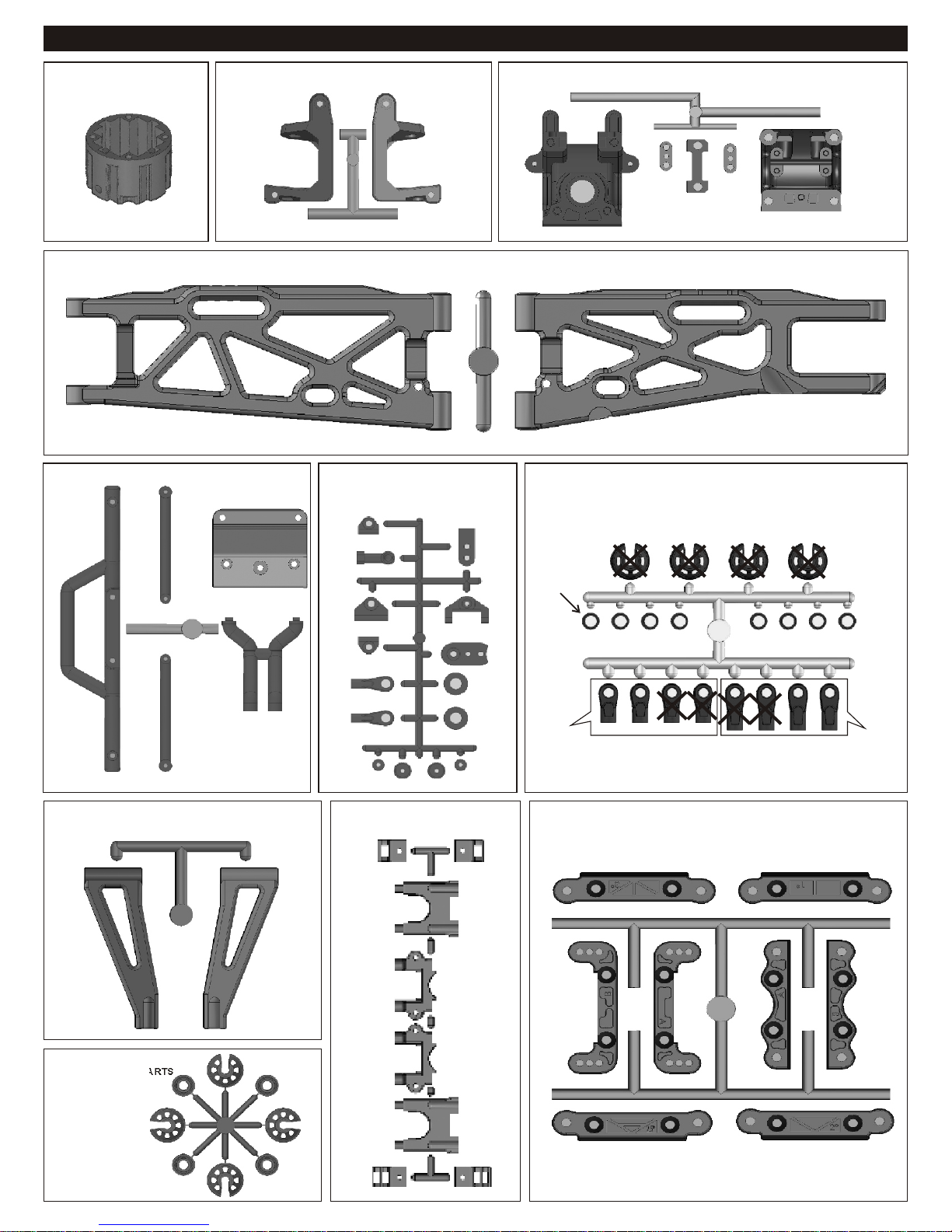
PLASTIC PARTS USED
40538
DIFF. CASE
40668
FRONT AND REAR LOWER ARM
40669
BUMPER
40536
FRONT C HUB
30802
Throttle Linkage Plastic
40533
FRONT AND REAR GEAR BOX
40643
SHOCK PLASTIC PARTS
41053
FRONT UPPER ARM
41036
CENTER DIFF. MOUNT
40643
Shock Cap
Washer
40643
Shock Plastic
Ball End
(Short)
40534
ARM HOLDER
40643
Shock Plastic
Ball End
(Long)
41008
SHOCK PLASTIC PARTS
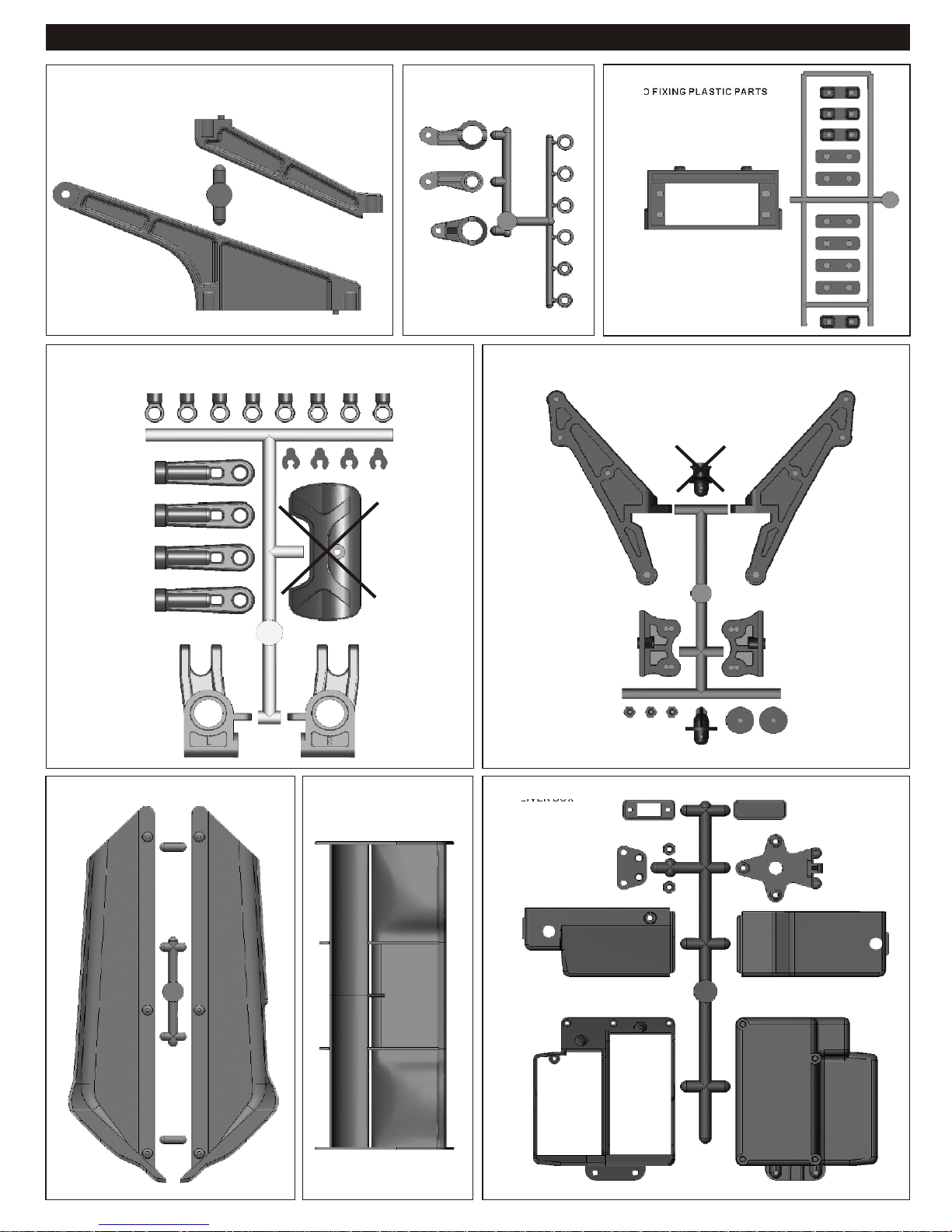
PLASTIC PARTS FOR USE
41034
CHASSIS BRACE
40540
REAR UPPER RIGHT/FRONT BUMPER
41052
SERVO SAVER
40542
WIN STAY
34026
PLASTIC PARTS SERVO FIXING
41033
STONE GUARD
16015
WING
40541
RECEIVER BOX
1
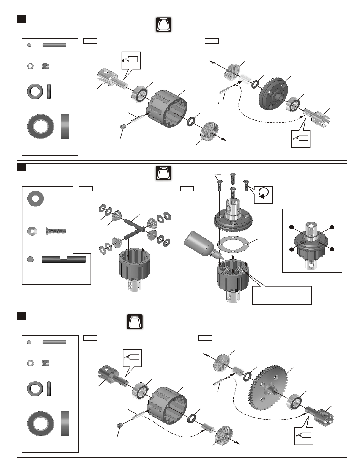
ASSEMBLY OF THE FRONT AND REAR DIFF.
Builds two differentials for front and rear.
BAG
NO.1
Step 1
40010
2.5x13.8mm Pin
94034
4x4mm
Set Screw
40009
P6 O-Ring
36053
8x16mm Ball Bearing
2
ASSEMBLY OF THE FRONT AND REAR DIFF.
30776
4x10mm Washer
.....x4
.....x2
.....x4
.....x4
.....x16
Oil
40596
40010
4x4mm
Step 1 Step 2
30776
40513
30774
36053
BAG
NO.1
40538
40513
Step 2
40009
3x12mm
40010
40513
40009
Tighten
41031
36053
40596
Oil
Tight the diff screws in this order.
1
3
94020
3x12mm
Flat Head Hex Screw
30774
4mm
Alum. Cross Pin
3
ASSEMBLY OF THE CENTER DIFF.
40010
2.5x13.8mm Pin
94034
4x4mm
Set Screw
40009
P6 O-Ring
.....x8
.....x4
Step 1
.....x2
.....x1
40605
.....x2
40010
BAG
Oil
NO.1
36053
40538
D
i f
.
Of
il
Step 2
40513
40010
40009
40011
4
*Put the Diff. Oil #7000 for front
and the #3000 for rear.
*Fill the Diff. case to approx. 80%
with the Diff. Oil.
40009
40518
2
36053
40605
36053
8x16mm Ball Bearing
.....x2
4x4mm
Oil
40513
1
4
ASSEMBLY OF THE CENTER DIFF.
Step 1 Step 2
30776
4x10mm Washer
.....x8
30776
40513
BAG
30774
NO.1
3x12mm
Tighten
Tight the diff screws in this order.
1
3
94020
3x12mm
Flat Head Hex Screw
30774
4mm
Alum. Cross Pin
5
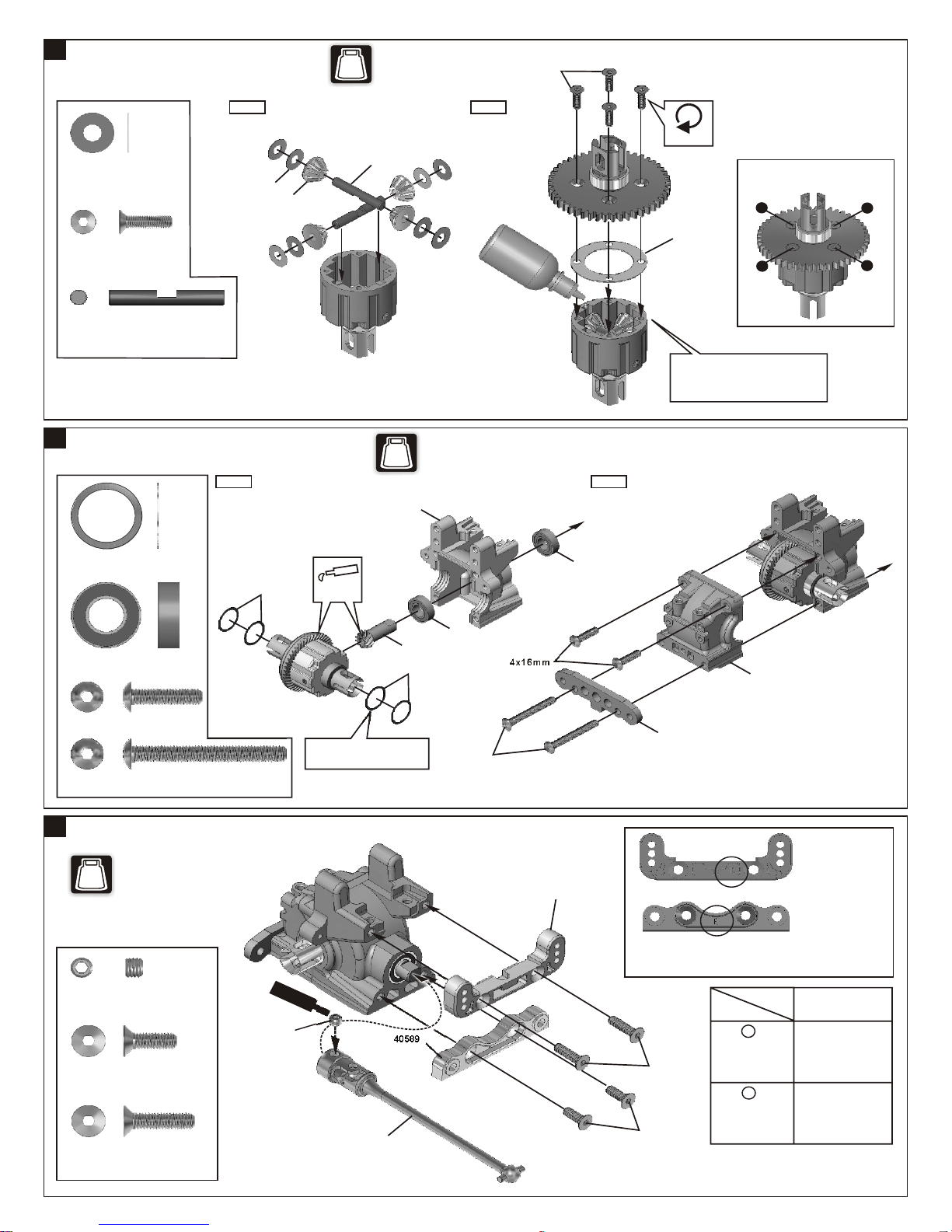
ASSEMBLY OF THE FRONT GEAR CASE
40024
13x16x0.2mm Shim
36053
8x16mm Ball Bearing
.....x4
.....x4
Step 1
.....x4
40024
.....x2
Apply
Grease
BAG
40533
41032
40024
NO.2
36053
Di f.
f Oi
4x16mm
40011
l
**Use 10000 weight diff. oil in the
center.
Fill the Diff. Case to approx. 80%
with the Diff.Oil.
Step 2
36053
4
40533
2
94011
4x16mm Hex Screw
94015
4x35mm Hex Screw
6
ASSEMBLY OF THE FRONT ARMS HOLDER
NO.2
BAG
94036
5x4mm
Set Screw
94026
4x12mm
Flat Head Hex Screw
94027
4x16mm
Flat Head Hex Screw
.....x2
.....x2
.....x1
.....x2
.....x2
5x4mm
Adjust the backlash with
the shims.
S
c
ew r
C m
e t
en
41044
40589
4x35mm
40534
40688
A
A
NB. use only as matched set "A"
with"A"and "B" with "B".
A
Caster
(High/22 Degree)
4x16mm
B
Caster
(Low/20 Degree)
4x12mm
Caster angle can
be changed with
A or B
Steering
Characteristics
Steering response
becomes milder.
Steering response
becomes quicker.
2
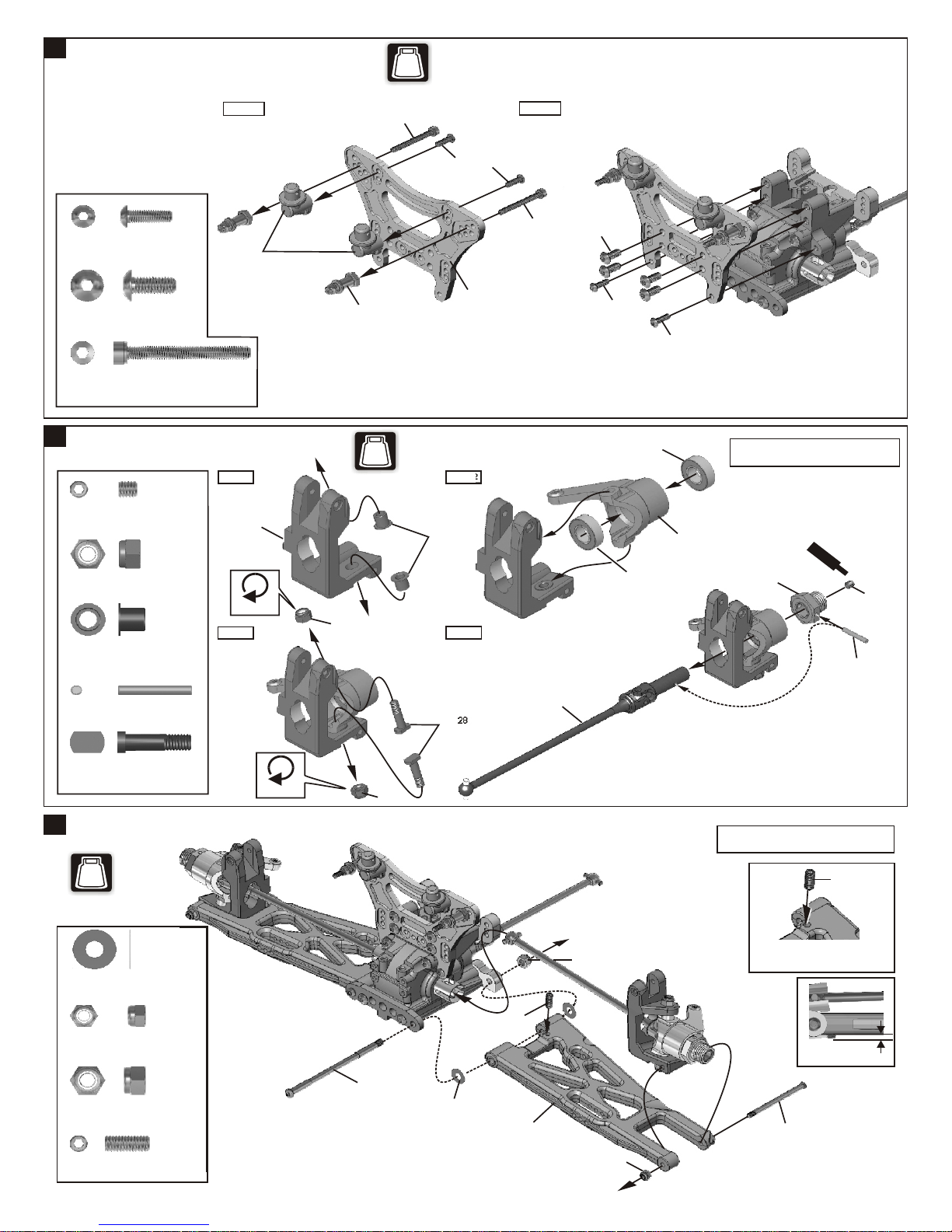
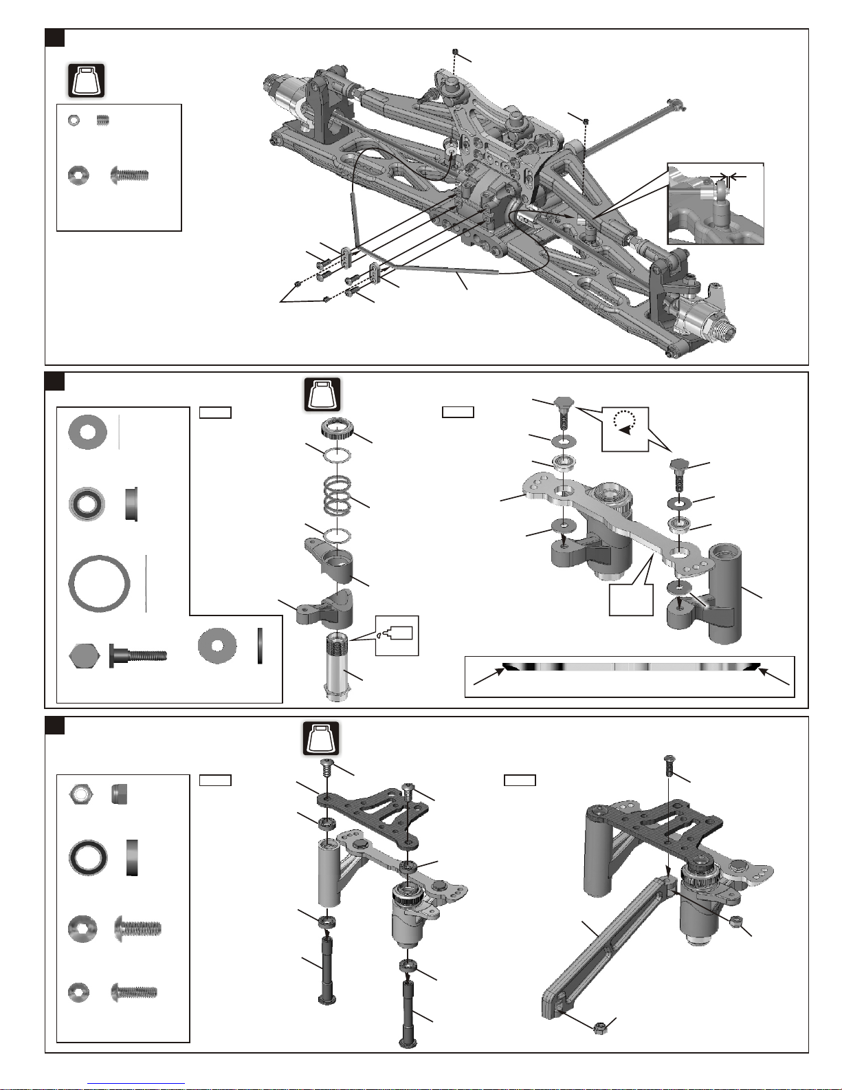
7
ASSEMBLY OF THE FRONT SHOCK STAY
BAG
NO.2
Step 1
94003
3x10mm
Hex Screw
94009
4x10mm
Hex Screw
41009
3x28mm
Cap Screw
8
ASSEMBLY OF THE KNUCKLE ARMS
94034
4x4mm
Set Screw
94042
4mm
Nylon Nut
40527
Knuckle Arm
Bushing
.....x4
.....x4
.....x2
.....x2
.....x4
.....x4
41035
Step 1
40536
Tighten
Step 3
4mm
41010
BAG
41009
NO.2
40527
3x10mm
40691
Step 2
Step 4
Step 2
41009
4x10mm
3x10mm
36053
36053
3x10mm
40570
Assemble both right and left sides
Sc
Cemen
r
ew
t
40526
4x4mm
36055
36055
2.5x16.8mm
Pin
40528
King Pin Screw
9
ASSEMBLY OF THE KNUCKLE ARMS INTO FRONT LOWER ARMS
NO.2
BAG
30776
4x10mm Washer
94041
3mm
Nylon Nut
94042
4mm
Nylon Nut
36870
4x10mm
Set Screw
.....x2
.....x4
.....x1
.....x2
.....x2
.....x2
Tighten
4mm
40604
Insert two 30776 washer
into arm shaft before
assembly.
40528
4x10mm
30776
40668
40657
4mm
3mm
Assemble both right and left sides
4x10mm
Set Screw
*A 4x10mm set screw is used
to adjust ride-height.
Approx 2mm
40602
(Short)
3
10
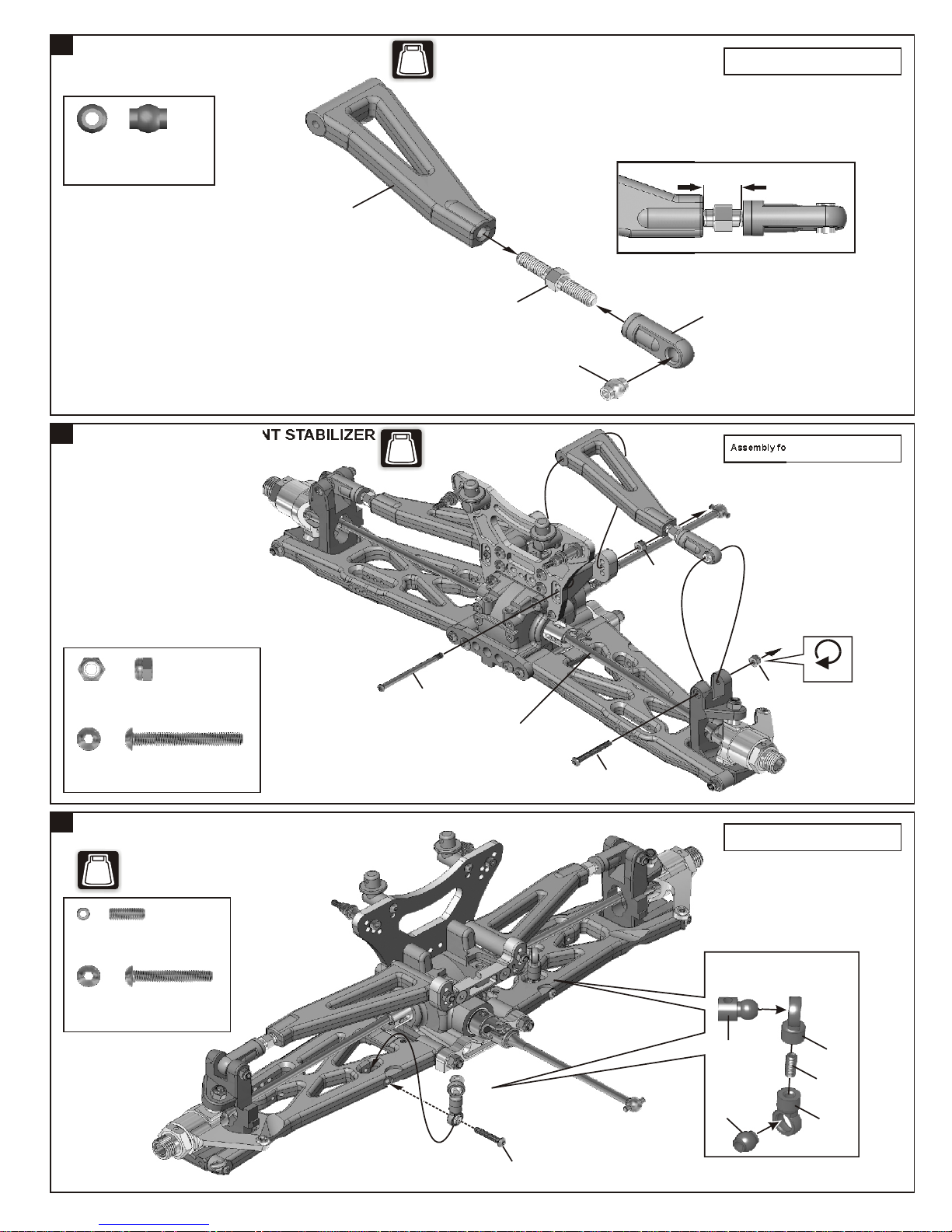
ASSEMBLY OF THE FRONT UPPER ARMS
36850
7mm
Ball and Socket
.....x2
41053
BAG
NO.2
Assembly for both right and left side.
11¡G
Approx. 9mm
11
ASSEMBLY OF THE FRONT STABILIZER
94041
3mm
Nylon Nut
94008
3x25mm
Hex Screw
.....x4
.....x2
BAG
NO.2
40602
Insert the drive shaft
into cap joint before
assembly.
36861
36850
3x25mm
3mm
36690
Assembly for both right and left side.
Tighten
3mm
12
ASSEMBLY OF THE FRONT STABILIZER
NO.2
BAG
94035
3x8mm
Set Screw
94006
3x18mm
Hex Screw
.....x2
.....x2
Assembly for both right and left side.
Makes two rods for left
and righthand-side.
30341
30403
3x18mm
40540
3x8mm
40540
4
13
ASSEMBLY OF THE FRONT STABILIZER
NO.2
BAG
94033
3x3mm
Set Screw
94035
3x8mm
Hex Screw
.....x4
.....x4
3x8mm
3x3mm
3x3mm
0.5mm
40533
14
ASSEMBLY OF THE SERVO SAVER
Step 1
30776
4x10mm Washer
40073
4x8mm Ball Bearing
40024
3x8mm Washer
40037
Steering Plat Screw
.....x2
.....x2
.....x2
.....x2
3x10x1.0mm
Washer
41052
.....x2
3x3mm
40024
40024
BAG
NO.4
40677
3x8mm
40034
41040
41052
Oil
40533
Step 2
40685
40560
40037
30776
40073
3x10mm
* Notice the direction of the servo saver connecting plate.
Do Not
Over Tighten
Ensure
Free
Movement
40037
30776
40073
3x10mm
41052
15
ASSEMBLY OF THE SERVO SAVER
40568
40074
40074
40511
94041
3mm
Nylon Nut
40074
6x10mm Ball Bushing
94009
4x10mm
Hex Screw
94003
3x10mm
Hex Screw
Step 1
.....x2
.....x4
.....x2
.....x1
BAG
NO.4
4x10mm
5
4x10mm
40074
40074
40511
Step 2
3x10mm
41034
3mm
3mm
 Loading...