

OFNA Racing Ultra LX Pro GT LX User Manual
1:8 SCALE GAS POWERED OFF-ROAD BUGGY
PLEASE READ INSTRUCTIONS CAREFULLY BEFORE ASSEMBLING
THIS MODEL.
KEEP THIS MANUAL FOR PARTS NUMBERS WHEN ORDERING.
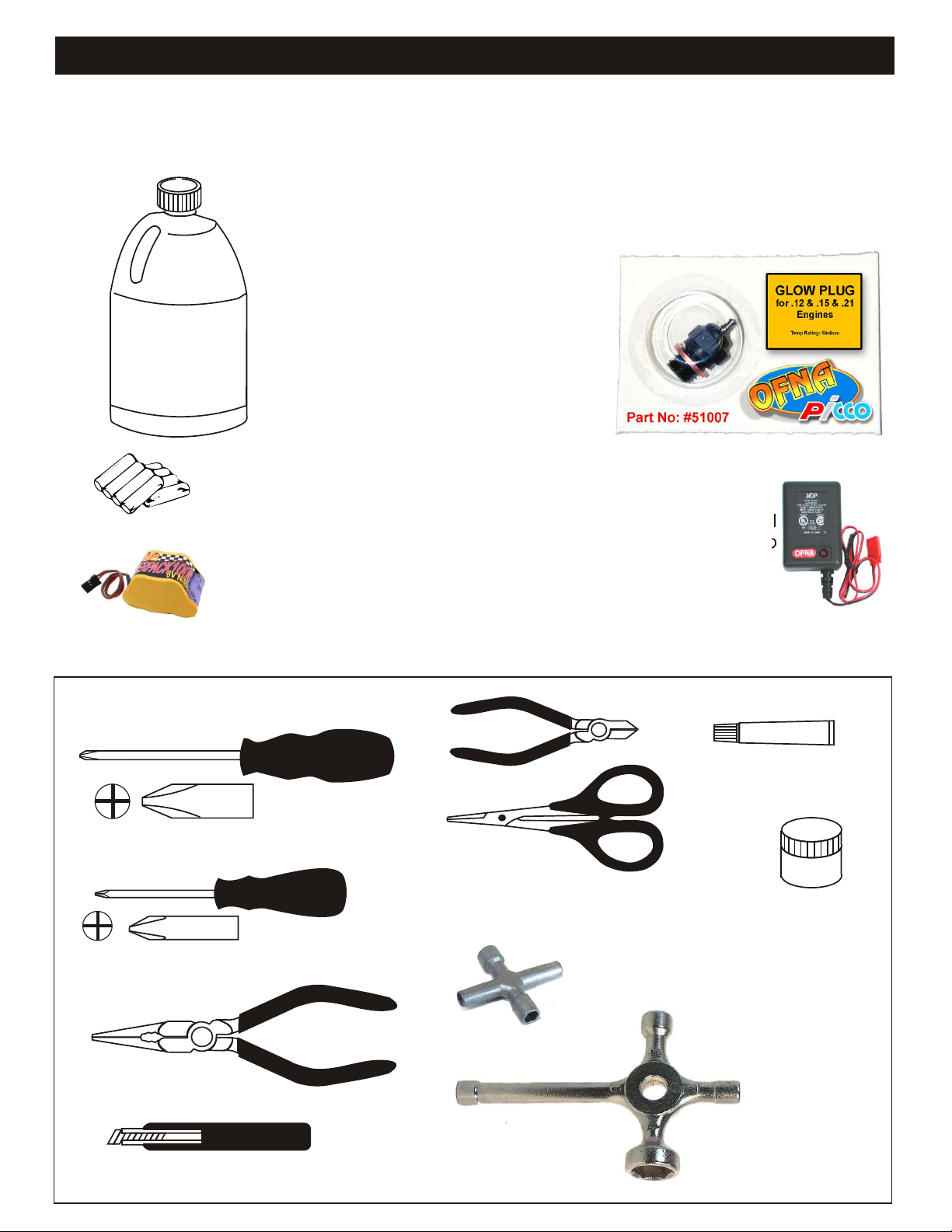
REQUIRED FOR OPERATION
THINGS NEEDED
Glow Fuel
20%
AA Batteries ( 12 pcs )
You will need to buy a few items to start the engine and run the car.
• Use 20% nitro CAR fuel. Do not use airplane or heli fuels, they will
over heat engine.
• Buy LONG glow plugs, like OFNA/PICCO Plug (#51007). Use plugs
without idle bar. Do NOT use plugs, like the MC-59 or OS-8
In your box you will find..
• #10163 - Bottle, spout top
• #10218 - Red “C” size glow heater
You need to get batteries for the radio transmitter and the car receiver
packs.
• Radio TX needs (8) eight AA batteries.
• Car needs (4) four AA Ni-cad batteries, Alkaline type batteries will
work, but braking will be reduced. The best is to use a 5 cell hump
pack for increased voltage..
Recommended Option:
#10212 NiHm Hump Pack,
see charger 10214.
TOOLS NOT INCLUDED IN KIT,
BUT NEEDED TO MAINTAIN YOUR CAR.
Phillips Type Screw Drivers ( L )
Phillips Type Screw Drivers ( S )
You may want to upgrade the car battery pack to a Ni-Cad or NiHm 5
cell type(600AE). This will give more run time. OFNA #10212
10214
Over-nite
Charger
Instant Cement
Cutter
Curved Scissors
Grease
Cross Wrench
#17109 $3.95
Needle Nose Pliers
Knife
Glow Plug & 17MM Cross Wrench
#10801 $6.95

MUST READ THIS BEFORE RUNNING
Running a nitro kit is fun and easy, but to make this a safe rusting.
and good experience you must observe a few rules. This
kit is extremely fast, easily over 40MPH, and can seriously
injure someone if you are not careful.
Where to run car?
• Any running area you choose must be dry. Do not run
car near any water or wet dirt.
• Do not run on public streets. It is very easy to have the
car run over or damaged by hitting the curb.
• Do not operate car in tight confined places. The car is
very fast and will easily hit something.
• Do not run near people or animals.
and will too easily hit someone.
• Due noise, you will want to consider the surrounding
area when operating the car.
• Do not operate the car at night. You will not be able to
drive it without hitting something.
• Do not operate the car indoors. Engine exhaust is not
healthy.
Glow Fuel
• Glow fuel is poisonous!
• Glow fuel is flammable!
• Do not leave in fuel bottle with lid off at any time. label for additional precautions.
• Do not use any fuel other than glow fuel in this engine.
First Time Starting the Engine
Caution! When starting engine make sure the following is
observed. • Always turn off the car BEFORE turning off radio.
• Set engine Master needle to 3 turns (rich setting)
• Do not do this alone, get an experienced friend to help at • DAMAGE DUE CAR RUN AWAY IS NOT A WARRANTY
first. ISSUE.
• Fill fuel tank, try not to spill fuel. Do not spill fuel on
receiver
• Hold car off the ground, so it will not runaway when first
starts
• Turn on Radio and check the linkage before starting
engine.
• Turn on car receiver battery switch.
• Always have an air filter on the carburetor to keep dirt
out.
Engine Break-in
• See Engine Page.
The car is very fast
• Clean oil and dirt from chassis with a degreaser.
Precautions
• This kit is not a toy. Always run car with a second
person as a spotter and pitman.
• Hot Parts - The pipe, manifold, engine and head are very
hot and will cause burns.
• Rotating Parts - Keep hands away from the drive train,
wheels, and engine when engine is running.
• Radio - Check batteries life before running the car. If
radio does not have full control of the car with steering
and/or throttle/brake do not run until corrected. Failure to
correct this will result in possible injury and damage to the
car or property.
• Glow fuel - Do leave the glow fuel unattended with the lid
off. Fuel contains Methanol and Nitro Methane and is
flammable and poisonous.
Store fuel in cool ventilated location. Refer the glow fuel
• Car Fuel tank - Never store fuel in car tank, it will ruin the
engine if left in tank.
IF YOU DO NOT BREAK-IN ENGINE
CORRECTLY, MAINLY AT LOW RPM,
YOU WILL BREAK THE CONNECTING
ROD!
FAILURE TO NOT READ AND
FOLLOW BREAK-IN ENGINE
Emergency Stopping Engine When Running
• Remove air filter and cover carb. intake.
• Squeeze fuel line and hold until engine stops.
• With a rag, cover exhaust outlet.
Storing Car After Running
• Remove fuel from tank and fuel lines
• Turn off radio in car
• Put a few drops of after run in engine to keep it from
INSTRUCTIONS WILL VOID
WARRANTY!
CHECK RADIO SETTING AND
LINKAGE BEFORE STARTING
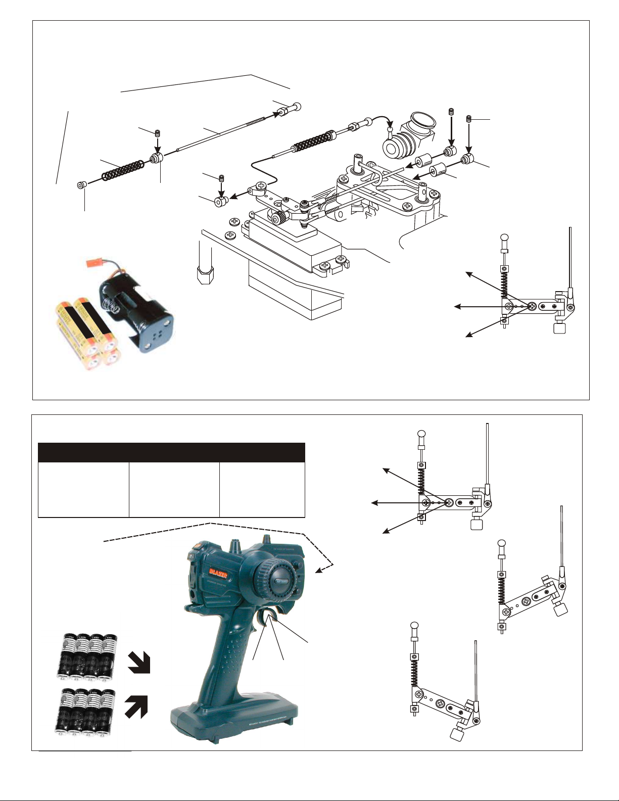
ASSEMBLY OF THE THROTTLE LINKAGE SYSTEM
#30800
Plastic Throttle
kit
Throttle
Spring
Plastic Collar
* Take the plastic collar
from brake system plastic
parts.
3X3mm
Set Screw
#30530
2mm Rod
3X3mm
Set Screw
Plastic Throttle
Ball Joint
* Snap On.
#10300
Alum.Stopper
Note:
Battery life is short when using Alkaline batteries. For safety, we recommend using
Alkaline batteries for only 30 minutes before testing; mostly changing. Battery strength
affects braking power and radio range. If voltage drops while running the car, you will
loose control and destroy your car! This is NOT covered under warranty.
To increase run time, upgrade receiver battery to a 5-cell hump pack. Also, install a
battery fail safe (OFNA # 91002) to further protect your car. But, the most important step
you can make, “is to always use fully charged or fresh batteries when running your car”.
Brake
Idle Position
Full Throttle
3X3mm
Set Screw
#10300
Alum.Stopper
Fuel
Tube
( 6mm )
* Align throttle servo same
as shown.
CHECKING ENGINE THROTTLE
A
1. Insert AA batteries into
transmitter (8 Pcs).
2.Turn on transmitter.
3.Turn on receiver.
4.Center throttle trims as
shown .
IMPORTANT
CHECK RADIO THROTTLE
AND STEERING SWITCHES
BEFORE RUNNING CAR
* Insert into transmitter.
1. Pull Full Throttle.
B
C
1. Push trigger to full
brake position.
2. Adjust alum. Stopper to
increase or decrease
the brake.
B
A
* Align throttle servo same
as shown.
Brake (C)
A
Idle Position (A)
Full Throttle (B)
• Full throttle arm position.
Spring rod pulls throttle
barrel open and brake
rods release pressure on
brake cams.
C
C
B
• Full brake arm position.
Spring compresses
forward and brake rods
pull brake levers.
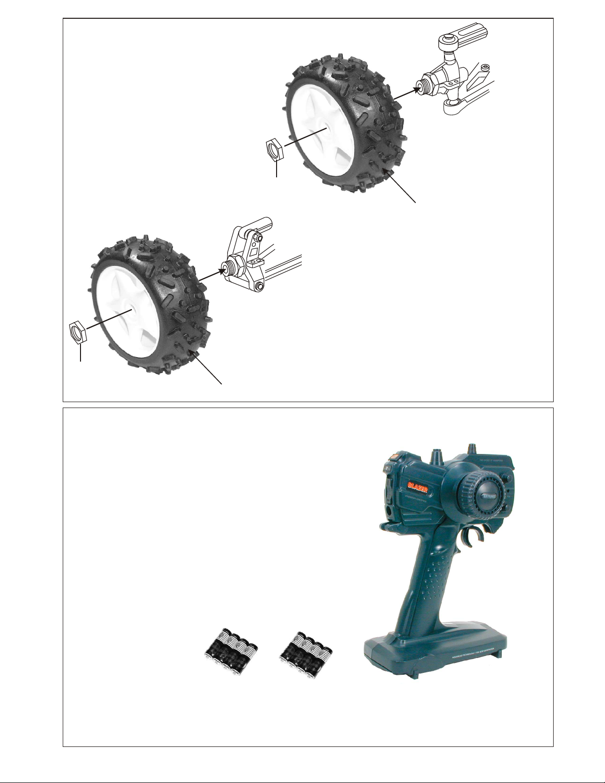
INSTALLATION OF THE TIRES AND WHEELS
15072
Nut, Blue
Wheel Nut
Rear Hub Assembly
Front Knuckle Arm
Assembly
Notice direction of the tire.
Note:
Make sure wheel nuts are tight before running your car.
Use a 17MM socket wrench to tighten these nuts. Spare nuts
in blue color are OFNA #15072.
Wheel Nut
Notice direction of the tire.
Note:
Battery life is short when using Alkaline batteries. For safety, we recommend checking
Alkaline batteries after 30 minutes. Battery strength affects radio range. If voltage drops
while running the car, you will loose control and destroy your car! This is NOT covered
under warranty.
To increase run time, upgrade receiver batteries to AA Ni-Cad or NiMH type. But, the most
important step you can make, “is to always use fully charged or fresh batteries when
running your car”.
Insert 8 pcs AA batteries into transmitter.
Radio shown may vary depending on
availability. Therefore radio pictured on
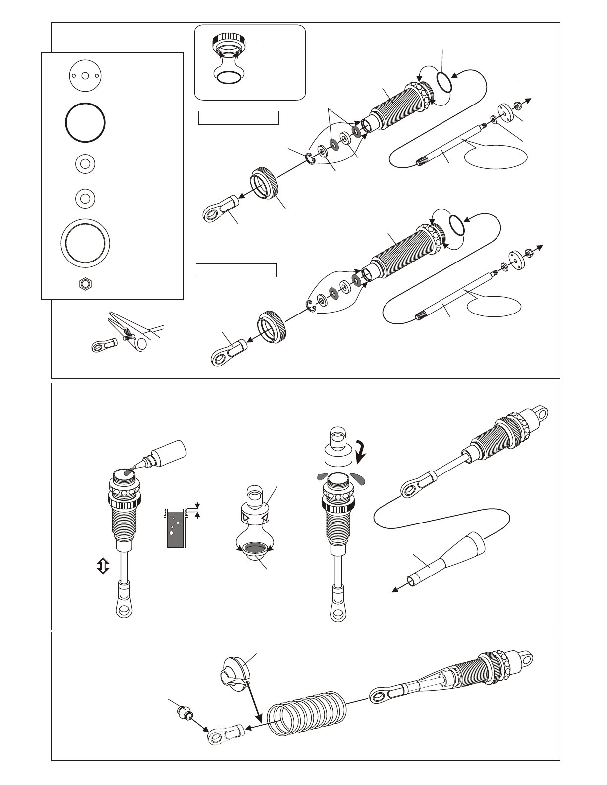
SHOCK ASSEMBLY
32235
Shock Piston.........4
40059
14.7mm O-Ring....4
40090
1mm Washer.............4
40090
2mm Washer..........4
49041
Spring Adjuster....4
40060
2.5mm Nylon Nut........4
49041
Spring
Adjuster
40059
14.7mm
Fit the O-ring into groove.
Make PAIR for Front
O-Ring
40056
Shock Plastic
Rod End
Make PAIR for Rear
40056
Shock Plastic
Rod End
40090
7mm R-Ring
49041
Spring
Adjuster
40090
3.5mm
O-Ring
40090
1mm
Washer
40076
Front Shock
Body
40090
2mm
Washer
40077
Rear Shock
Body
40059
Oil Seal
* Short shaft
for front.
40054
Short Shaft, Front
40055
Long Shaft, Rear
40060
2.5mm
Nylon Nut
32235
Shock
Piston
2.6 x 5mm
Washer
* Long shaft
for rear.
* Be careful not to damage shock shaft
or over tighten threads.
FILLING THE SHOCKS WITH OIL
1. Pull down piston and pour oil into
shock cylinder. Remove air bubbles
by slowly moving piston up and down.
OIL
*Leave 3mm.
UP
down.
*Move Slowly.
ASSEMBLY OF THE SPRING
30411
6mm Ball
* Push 6mm ball joint
into ball end.
2. Pull down piston, attach pressure top
and shock oil overflow with tissue
paper.
3. Tighten up shock cap.
40093
Shock caps, Hard coated
Cap
40058
Shock Shaft
Dust Cover
32033
Pressure Top
Fit into the groove.
*
40063
Spring Holder
40069
Shock Spring, Black
4. Assembly the dust cover.
40052 - Front Shock Set
40053 - Rear Shock Set
40069 - Spring Set, black (stock)
40070 - Spring Set, Green (soft)
40071 - Spring Set, Blue (med)
40072 - Spring Set, White (hard)
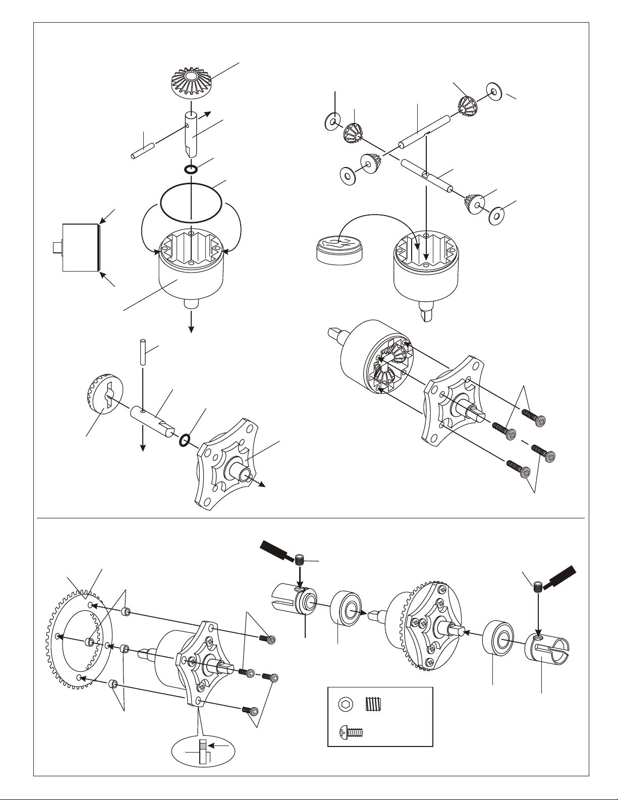
ASSEMBLY OF THE FRONT AND REAR AND CENTER DIFFERENTIALS
31324 - FRONT OR REAR DIFF UNIT
31325 - CENTER DIFF UNIT
30779
2 x 12.8mm
Pin
* Position the O-ring
as shown.
30751 Diff. Case ( Front/Rear )
30761 Diff. Case (Center )
30779
2 x 12.8mm
Pin
30771
Diff. Shaft
30769
Diff.
Bevel Gear
( Large )
30769
Diff. Bevel Gear
( Large )
30771
Diff. Shaft
30779
P5 O-Ring
( Orange )
30779
0.5 x 26mm
O-Ring
30779
P5 O-Ring
( Orange )
30779
4 x 10mm
Washer
Grease
* Apply diff. Gear grease to the
differential, during assembly.
* Fill the diff. Case to
approx 70% with grease.
30751 Diff. Case ( Front/Rear )
30761 Diff. Case (Center )
30769
Diff.
Bevel Gear
( Small )
30773
4mm
Cross Pin
30769
Diff.
Bevel Gear
( Small )
30773
4mm
Cross Pin
30779
4 x 10mm
Washer
30769
Diff.
Bevel Gear
( Small )
30779
4 x 10mm
Washer
Note:
Always use shims as shown.
30779
3x10mm
Screw
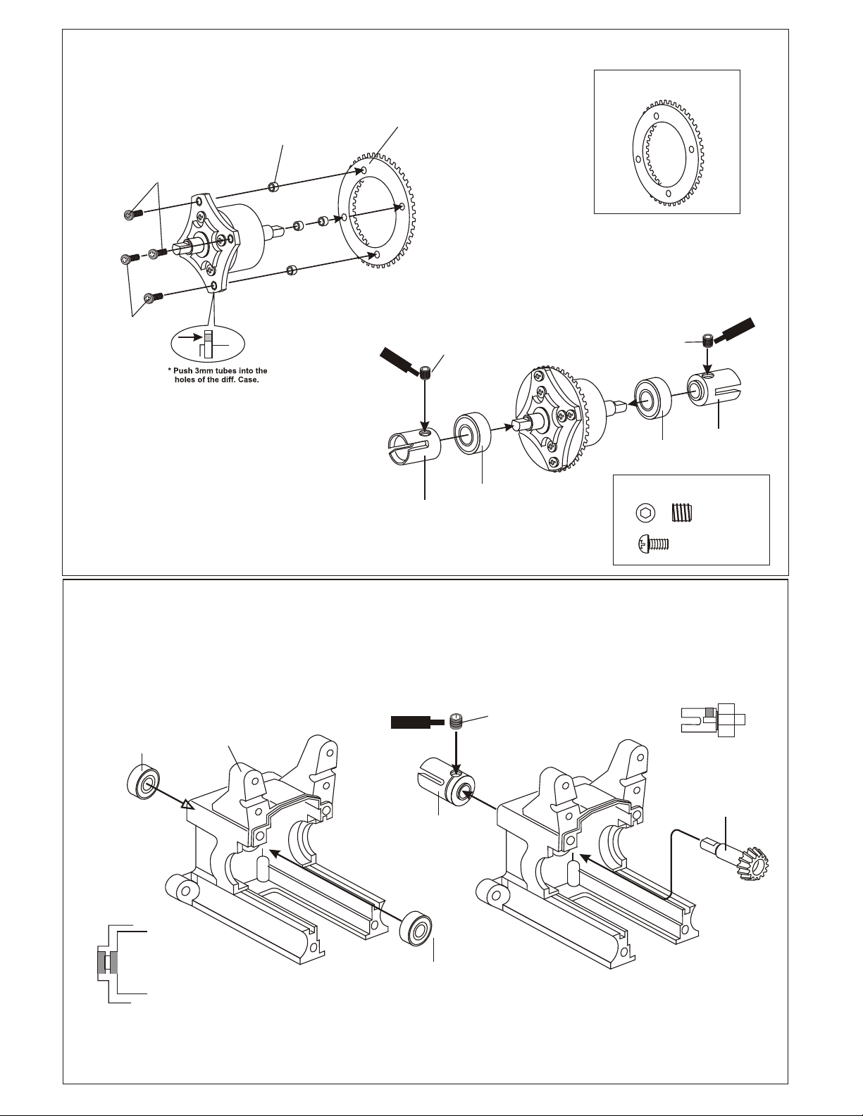
ASSEMBLY OF THE BEVEL GEAR
30120
Bevel Gear
(Large/Metal)
* Push 3mm tubes into
holes of the diff. Case.
31010
Optional - Bevel Gear
(Harden Steel)
30121
3mm
Tube
30121
3mm
Tube
* Notice the straight holes
are for front and rear.
( Builds two differentials, for front and rear. )
Screw
Cement
90026
5 x 5mm
30121
Set Screw
3 x 5mm
Screw
36730
Cap Joint
30620
7 x 19mm
Bal lbearings
30121
3 x 5mm
Screw
(Small Head)
30701 - Hex Screws, Misc. Sizes
5 x 5mm
Set Screw
3 x 5mm
Screw
30779
3x10mm
Screw
90026
5 x 5mm
Set Screw
30620
7 x 19mm
Ball bearings
Sc
39730
Cap Joint
w
t
re
men
Ce
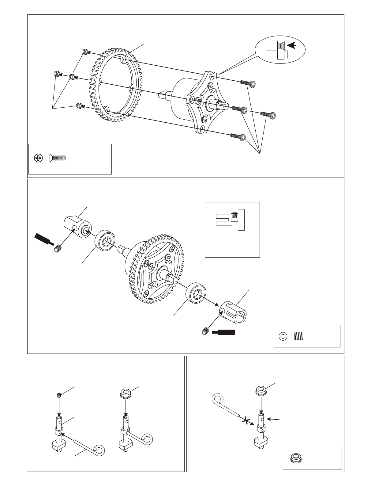
ASSEMBLY OF THE SPUR GEAR
35314
M3 Nylok Nut
30111
Spur Gear Mount
Hardwares
Note case direction for screw head.
31040
Spur Gear, Steel
30111
3X10mm
Screws
ASSEMBLY OF THE CENTER BRAKE CAP JOINT
30170
Joint Cap, Flat,
Center Brake Disc.
Sc
rew
Ce
m
ent
30620
30711
Misc. Hex Screw
Bag
30620
7x19x5mm
7x19x5mm
Ball Bearing
Ball Bearing
30620
7x19x5mm
Ball Bearing
Joint cap
Tighten hex screw on
flat of shaft. Always
check, if not sure. Car
will move if loose.
30711
Misc. Hex Screw
Bag
Screw
Cement
30111
3X10mm
Screws
30170
Joint Cap, Flat,
Center Brake Disc.
30701
Misc. Hex Screw
Bag
ASSEMBLY OF THE BRAKE CAM FOR FRONT ASSEMBLY OF THE BRAKE CAM FOR REAR
30211
30701
M3x3
Hex Screw
30213
Cam, Brake
30171
Lever, Brake Cam
30211
5x8x2.5mm
Bushing
30212 (option)
5x8x2.5mm
Ball Bearing
30171
Lever, Brake Cam
5x8x2.5mm
Bushing
30212 (option)
5x8x2.5mm
Ball Bearing
Use top hole in cam for lever.
Place bearing and plate first
before tightening lever.
30212 (option)
5x8x2.5mm
Ball Bearing
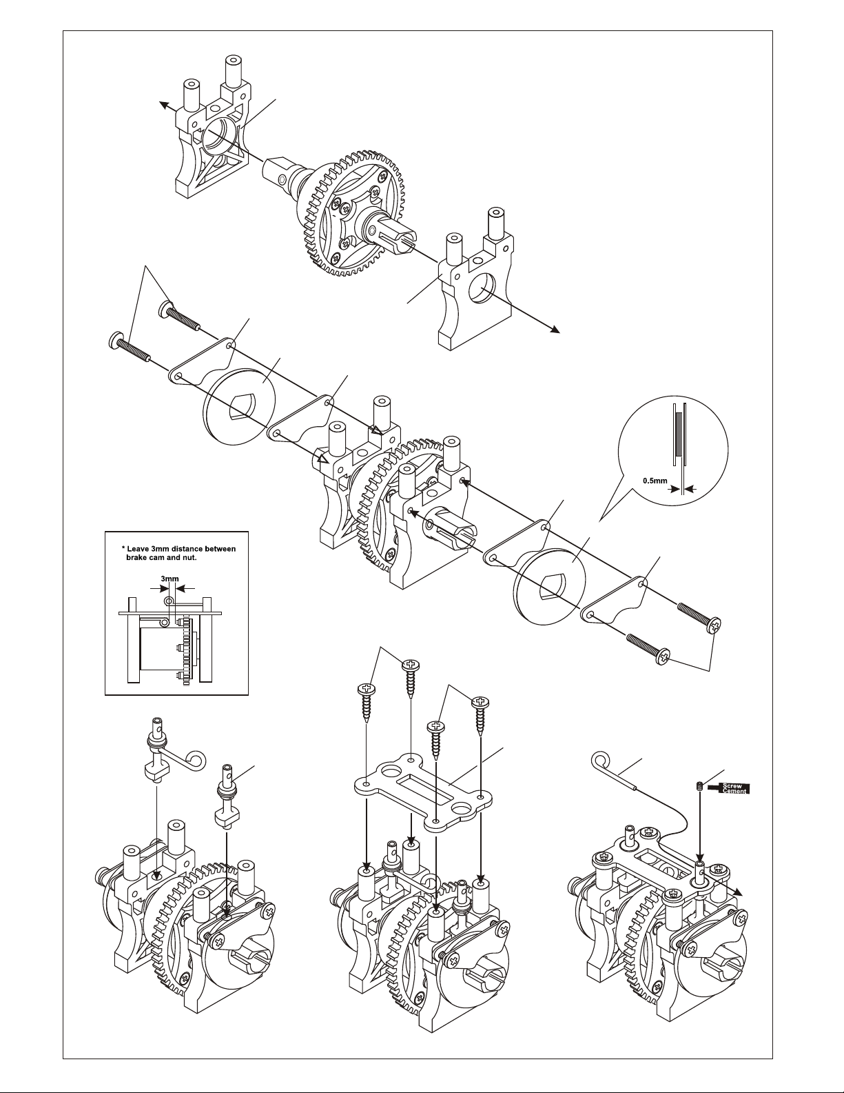
ASSEMBLY OF THE CENTER DIFF. MOUNT
30201
Center Diff. Mount
3x15mm
Screws
30180
Brake Pads
31020
Brake Disc.
30201
Center Diff. Mount
30180
Brake Pads
M3x12
Tapping Screws
Note:
Adjust brake pads for a o.5mm gap. If gap is
to big, the lever not move enough to apply
braking.
30180
Brake Pads
31020
Brake Disc.
30180
Brake Pads
M3x12
Tapping Screws
3x15mm
Screws
Rear Cam
Lower Hole Used
Front Cam
30652
Center Plate
Diff must turn freely.
Check brake pad
spacing.
Front
30171
Lever, Rod
3x3mm
Hex Screw
ASSEMBLY OF THE BEVEL GEAR
30121
Mounting Hardware
insert tubes, 4 pcs.
30121
Mounting Hardware
31010
Bevel Gear. Large, Harden
30120
Bevel Gear. Large
ASSEMBLY OF THE GEAR BOX
( Assemble two gear boxes, front and rear. )
1
30630
6 x 13 x 5mm
Ball Bearing
30010
Gear Box
Ce
Sc
me
rew
n
Screw
Cement
t
30082
Joint Cap
90026
5x5mm
Hex Screw
2
30620
7x10mm
Ball Bearing
90026
5 x 5mm
Set Screw
90026
5x5mm
Hex Screw
Tighten hex screw on
flat of shaft.
ent
crew
S
em
C
30082
Joint Cap
90026
5x5mm
Hex Screw
30121
Mounting Hardware
The Pinion Gear is held in place
by two bearings.
30130
Pinion Gear,
Harden Steel
30082
Cap Joint
30630
6 x 13 x 5mm
Ball Bearing
 Loading...