


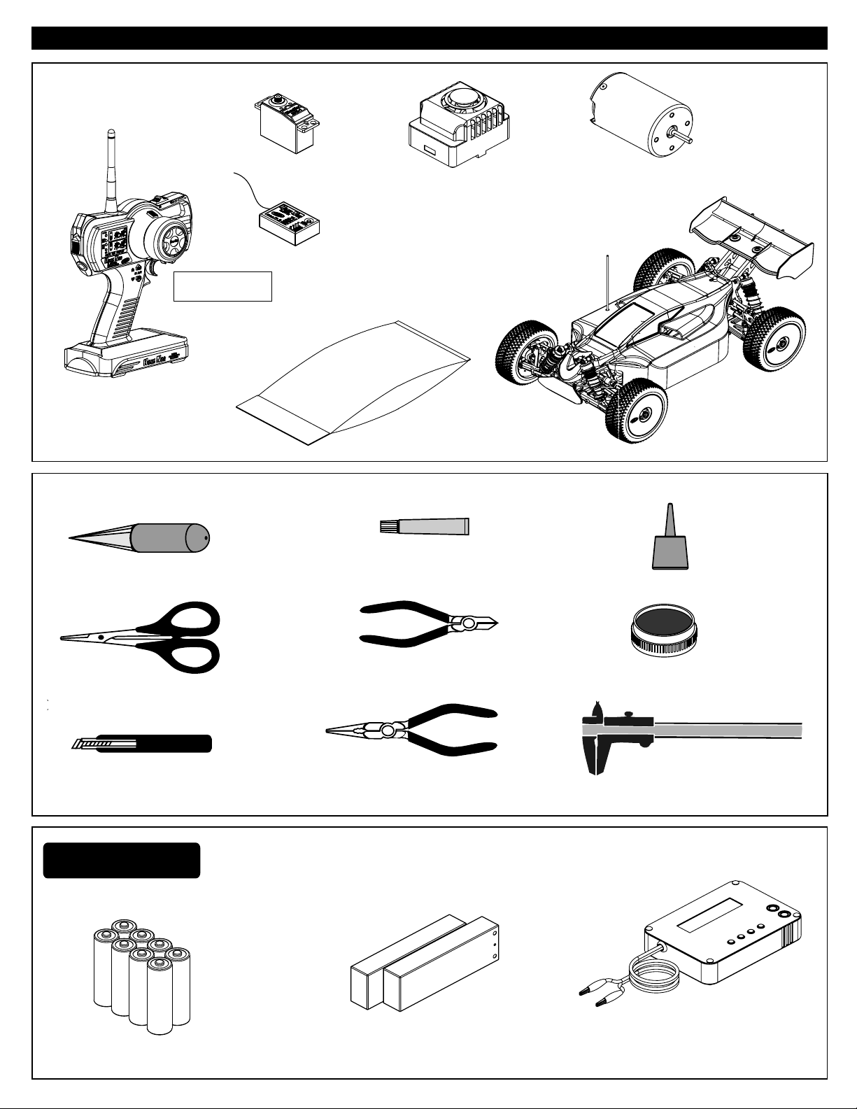
Components
OVERVIEW
Transmitter
Body Reamer
Radio System
40991
Servo
Receiver
Parts Bag
Brushless Electric
Speed Controller (30693)
Radio Control Car
TOOLS NOT INCLUDED IN THE KIT
Screw Cement
Screw Cement
Brushless Motor,1900KV
( 30694)
CA
Instant Cemment
Curved Scissors
Craft Knife
Equipment Needed
AA Batteries
( 8 pcs )
Cutter
Needle Nosed Pliers
7.4V L
i-Po Battery
(Hard Case x2 pcs)
GEAR
GREASE
Gear Grease
Precision Caliper
TOOLS NOT INCLUDED IN THE KIT
Included Item
s
1.5mm Allen Wrenc
h
2mm Allen Wrenc
h
2.5mm Allen Wrenc
h
Cutte
r
Curved Scissors
Craft Knife
Precision Caliper
Needle Nosed Pliers
Equipment Neede
d
L Battery Chargeri-Po
ATTENTION
•Before plugging in your batteries and turning on your radio
please read this page!
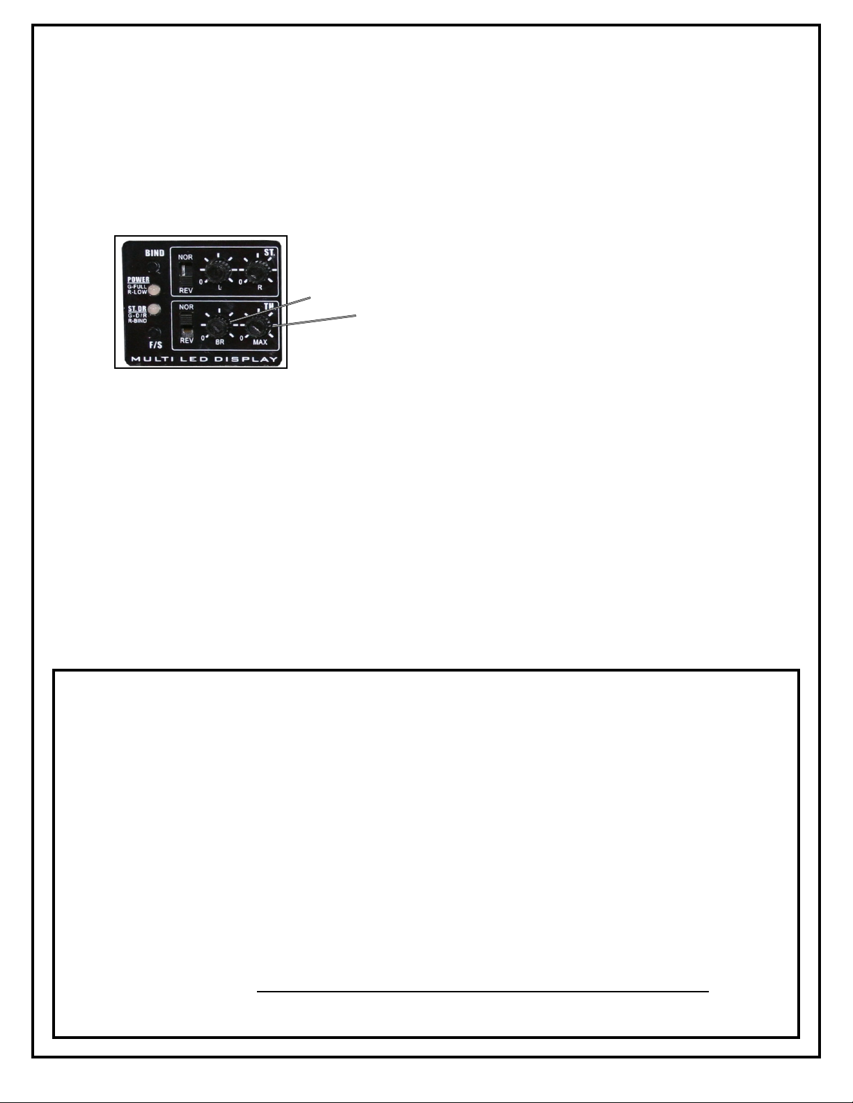
1. Check your brake and throttle dial on transmitter, and make sure it at MAX.
Brake
Forward
2. Turn on your transmitter.
3. Plug in your two 7.4v Lipo batteries.
4. Turn the switch to ON (Electronic Speed Control)
A. It will beep twice and LED will flash RED
B. Then the LED will go to solid Green on both LED
5. Now check your Throttle and Brake by slowly pulling the trigger.
(Make sure you don’t free wheel the buggy drive it around slowly)
6. Now everything should sync up you are ready to play.
For more instruction on all the function on your radio please refer to
pages 5-11 of this manual.
NOTE!
This model comes equipped with
a 14 tooth pinion gear. Do not
change the pinion gear to a higher
number tooth count. This can
cause motor and E.S.C. Damage
and will VOID THE WARRANTY!

5
HNT-3 2.4GHz RADIO SYSTEM OVERVIEW
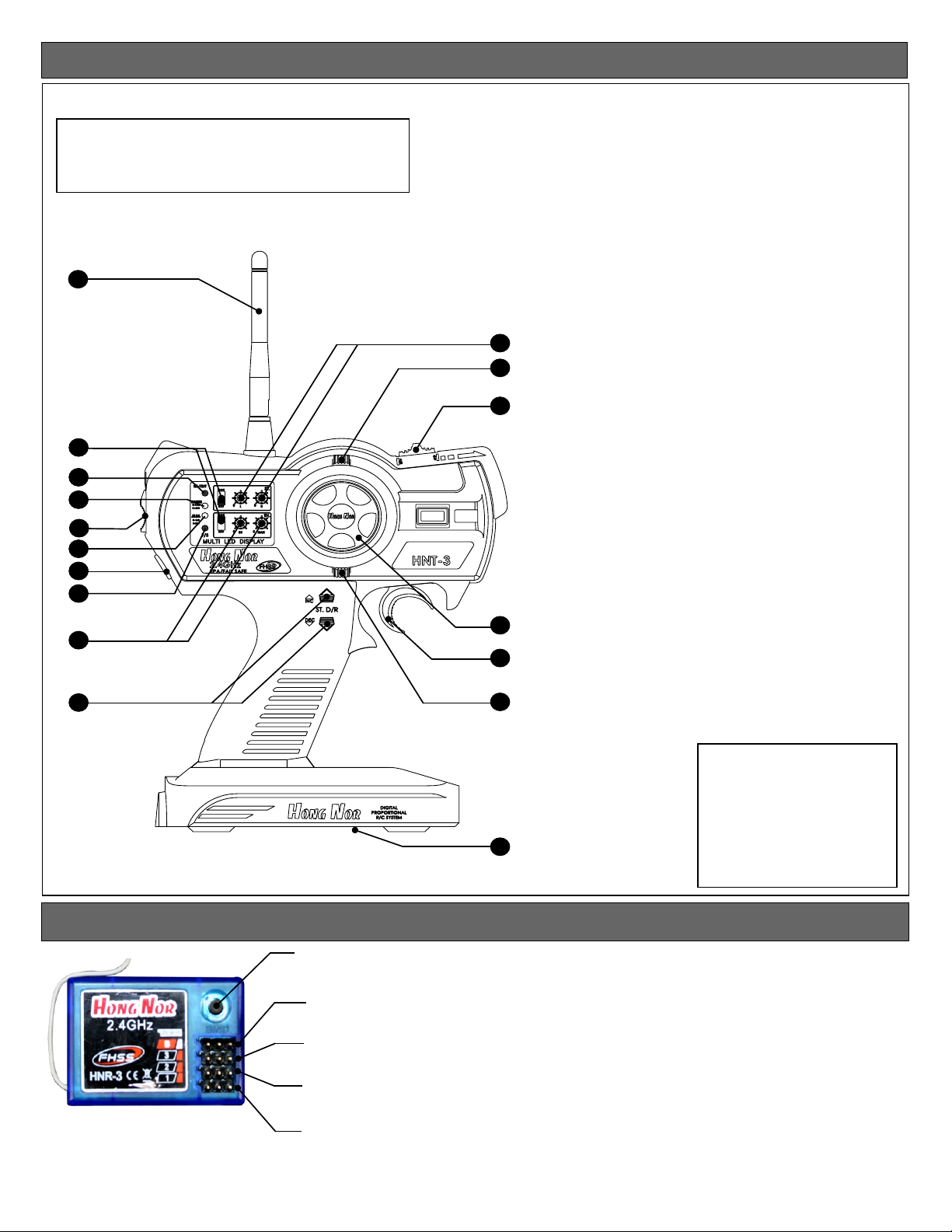
HNT-3 Transmitter
*Carefully read the instruction manual of your
radio controller before using and keep it in a
safe place as a reference introduction in the
future.
1
2
3
4
5
6
7
8
10
12
14
1.Transmitter Antenna
2.Servo Reverse Switches
3.TX RF Module And Binding Button
4.Power LED
5.Power Switch
6.Steering Dual Rate Trim LED
7.External Charging Jack
8.Fail Safe Button
9.Throttle End Point Adjustment Knob
10.Steering End Point Adjustment Knob
11.Steering Dual Rate Adjustment Button
12.Steering Trim
13.Throttle Trim
14.AUX Channel Switch
9
11
Receiver Connection Diagram
Bind Button
Battery Port
Auxiliary Channel
Throttle Channel
Steering Channel
15
16
13
17
15.Steering Wheel
16.Throttle Trigger
17.Battery Cover
Specification Data
•Transmitter
Channels: 3
Frequency: 2.4Ghz
Power DC: 9.6V - 12V
Measurement: 280 x 190 x 85mm
(Packing Meas.)
Net Weight: 510g
Specification:
Channels:3Ch
Frequency:2.4GHz
DC:12V/ 8 cell AA Type
Battery
Meas.:310*170*75mm
Net weight:530g
•Receiver
Channels: 3
Frequency: 2.4Ghz
Power DC: 4.8 - 5.6V
Net Weight: 13.5g
6
CAUTION
• To use your Radio with your models correctly and safely, read this manual carefully and keep it in a
safe place for future reference.
Warning:
1. This product is only equipped for radio controlled cars;
2. The usage of this product should be approved by local law or regulations;
3. We will not be responsible for the damages caused by unauthorized modification, adjustment
or replacement of parts on this product;
4. The manual may be change without prior notice. Please contact us if you have any corrections
or clarifications that should be made in the manual;
• Before turning on the transmitter, make sure the transmitter batteries are fresh. The voltage of the
transmitter batteries is should never be lower than 9.6V, and please check and confirm that the servos
are all well and properly connected.
• Keep the radio system away from moist, high temperature and strong vibrations. Do not clean radio
with any solvent.
• Make sure antenna does not touch anything when power switch is turned on. Do not leave this radio
in reach of small children.
• Please use this product according to your local laws and regulations, we are not responsible for any
incidents or damages.
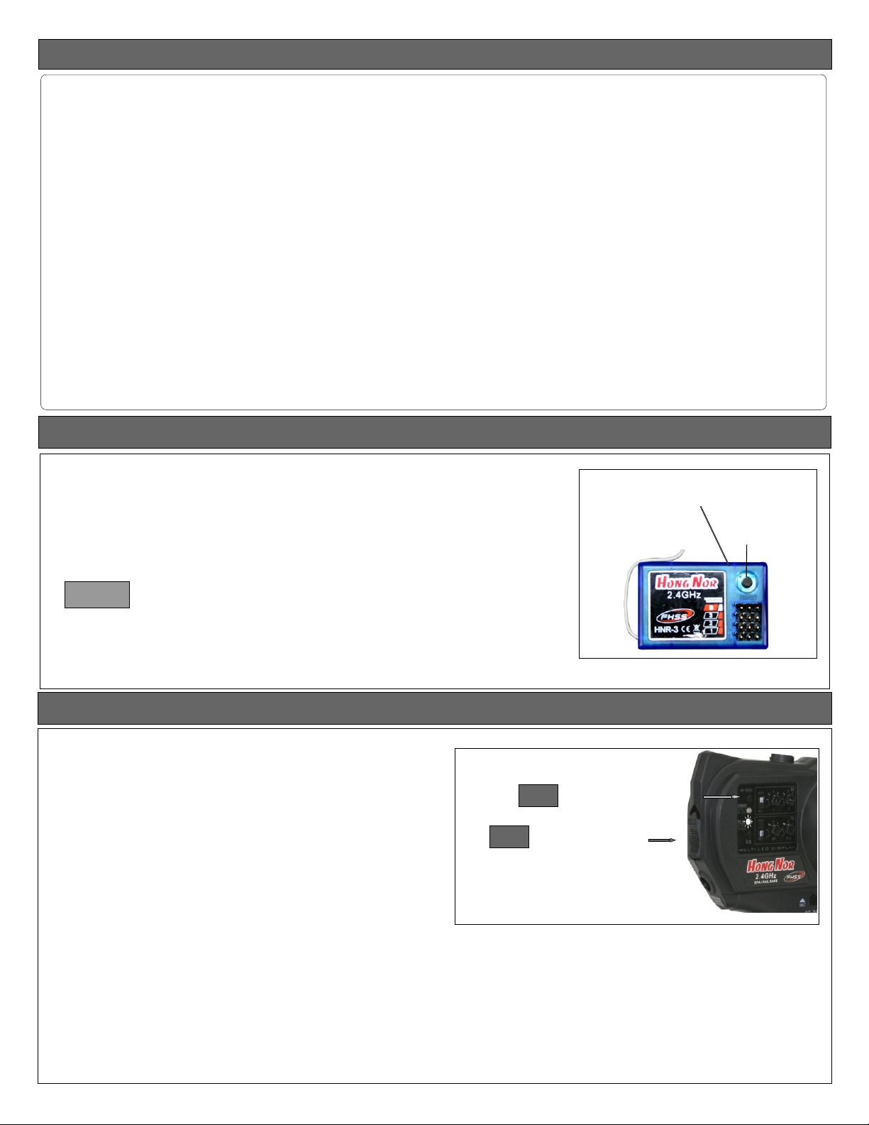
2.4Ghz Binding
•Binding your RX to Transmitter
Turn on the transmitter, then turn on your ESC (speed control)
or receiver power switch. Then push the bind button located on
the receiver until LED light turns solid green which is about 3 sec.
Green which means the binding is successful. After that, it’s un necessary to bind again.
LED
BIND
Caution:
When binding make sure that the RX and TX is no more
than a yard or 3 feet from each other, also no other similar FHSS
system or device is being use within 10 yard of your RX and TX
or it could accidentally pair up or bind with your vehicle.
Reducing Power
• Reducing output power setting.
• Push the RF-TEST button, while holding it down turn on your transmitter,
the “ST-D/R” LED “RED” should light up. Now your output power of the
transmitter is reduce to a lower mode of 18dbm, which reduce the range
of the radio but save in battery consumption
.
•Now press the RF-TEST button again, the LED on the “ST-D/R should turn off, and
output power becomes normal 20dbm which can control your vehicle with more
range but more battery consumption.
STEP 1
STEP 2
Power Switch (turn on)
RF-TEST (Press and hold)
7
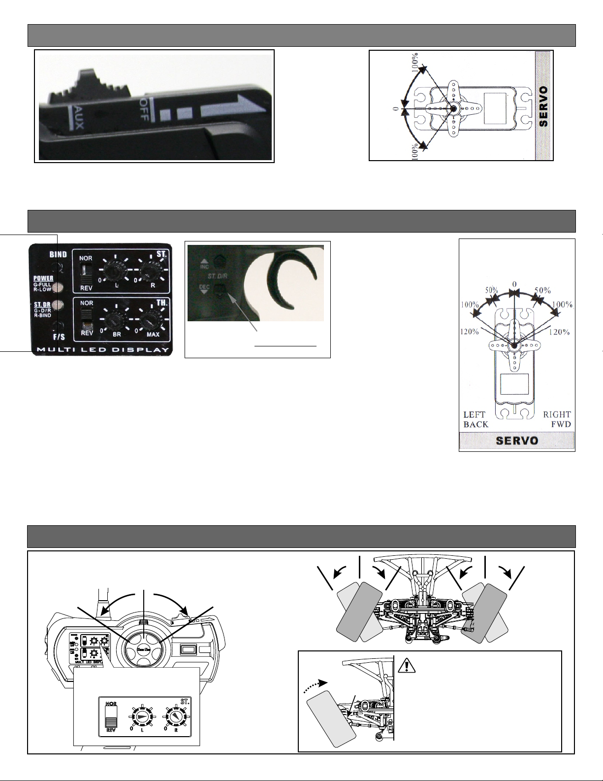
AUX Channel Function (CH3)
•This switch control the transmitter’s third channel. A servo plugged in this Channel 3 will move to full travel in one
direction when the switch is in the “AUX” position, then move the switch to the “OFF” position the servo will move
in the opposite position . This channel can be use to turn on all sort of things in your vehicle. For example, lights,
on board camera etc..... l
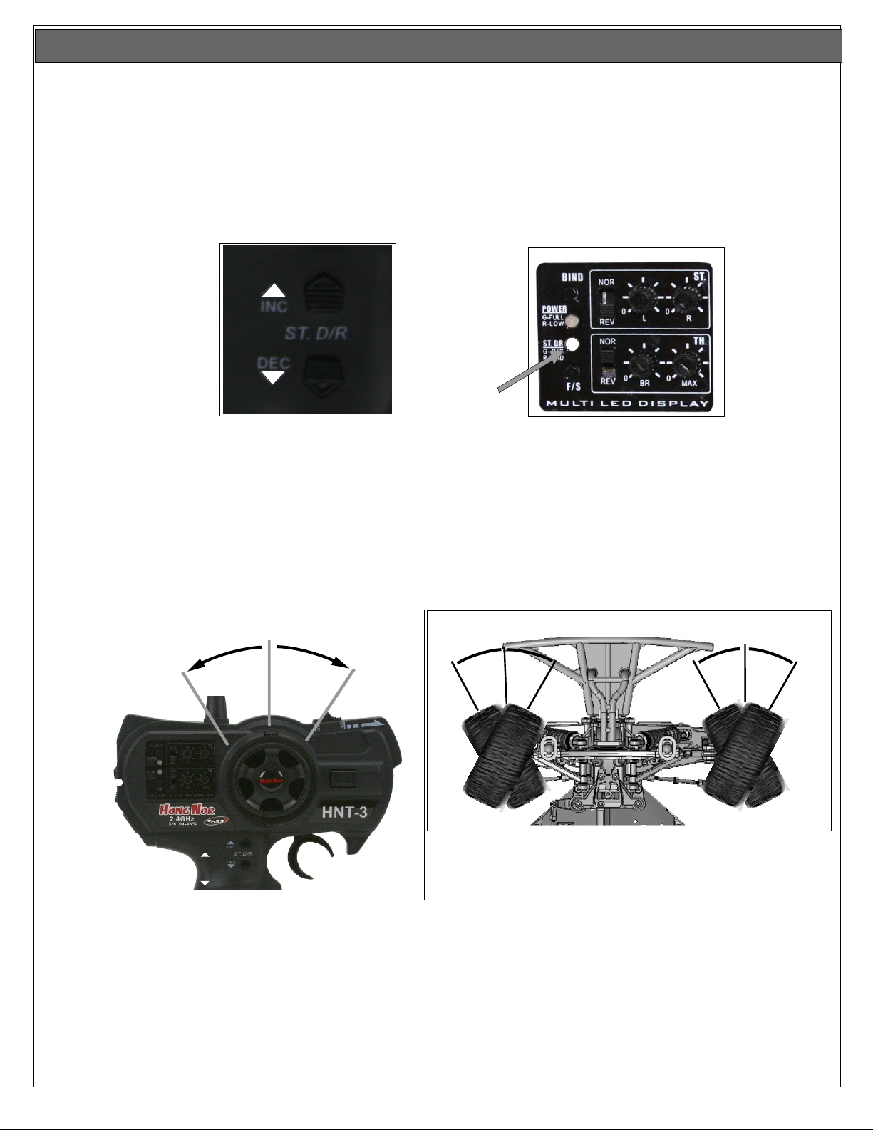
Steering Dual Rates Setup
INC
ST.DR
DEC
ST.D/R SW
•DEFINITION:
Steering Dual Rate (ST. DR): Is the adjustment that allows the dual rate value
(maximum servo travel) to be increased (INC) or decreased(DEC) with in a range
of 0% to 100% of the steering servo. This functions very useful in a race
conditions as it allows you to tailor the steering radius and sensitivity for the
current track conditions.
•ADJUSTMENT:
1.Press and hold the “INC” (Increase) button until the LED on the “ST.DR” blinking green
into a blinking red indicating maximum turning radius or value of 100%.
2.Press and hold the “DEC” (Decrease) button until the LED on the ‘ST.DR” start blinking green
and goes to a blinking red LED indicating minimum turning radius or value 0%.
Steering End Point Adjustment (EPA)
Steering End Point Adjustment (ST.EPA)
Left turn
Straight (neutral)
L R
Right turn
L R
*L/R Steering end point adjustment
(ST. EPA)knob.
Max Max
Use the "EPA" to adjust steering tie-rod to
the steering stopper.
Steering
Stopper
*After adjusting "D/R" to Max position then adjust
both "ST EPA" knob to the correct position as
picture shown.
*The steering stopper may vary for different
brand models. Follow the steering stopper
set-up for max position. The steering servo
may be damaged if it is overload.
8
CHECKING YOUR DUAL RATE
•To Check Your Dual Rate:
1. Turn your radio “ON” then turn “ON” your vehicle.
2. Check your steering on your radio by turning left and right several times.
3. Now turn your steering wheel all the way to the left or right whichever you choose
and hold it while pushing the “DEC” button ( see fig. 1) on the “ST-DR” and
hold it down, you should see that the wheel on your vehicle decrease in radius
(see fig. 2) and that the LED on “ST-DR” will start blinking Green and turn to a
blinking Red indicating it is at 0% or minimal steering radius
FIG. 1
INC
ST. D/R
DEC
FLASHING
.
4. To increase the dual rate turn the wheel left or right all the way and hold it while
pushing the “INC” button this will increase the turning radius of the and the LED
on ST-DR will start blinking Green and turning to the FIRST Blinking Red indicating
that the“Dual Rate” is at 80%, Holding the increase button past the FIRST Blinking
Red will turn to Blinking Green again then to the SECOND Blinking Red indicating
your “Dual Rate” is at 100%. When running your vehicle try to run the “Dual Rate”
at maximum radius (100%). Then if you have too much steering then decease as
needed.
FIG. 3
ST.DR
0%
%
001
INC
ST.D/R
DEC
100
%
FIG. 2
0
0
1
0%
%
10
0
%
0
0
1
0%
%
1
00
%
9

Steering Trim
Please turn on your transmitter, plug in your battery and turn on your esc while making the adjustment of these settings.
1.Connect the receivers, servos, and other components and then turn on the power switches of the transmitter and receiver.
2.Be sure the steering trim and throttle trim on the transmitter are at their neutral position.
3.When turning on your system make sure you turn on the transmitter first before turning on the receiver, while turning off the system
turn of receiver before turning off the transmitter.
•Steering Trim
Steering neutral adjustment can be made by moving the steering trim knob to the left or right.
•Finding Neutral position on the Steering
To find the center or neutral position on your transmitter, turn it on. Push the “ST-TRIM” left and notice the “ST-DR” will start flashing Green
then slowly turn to a flashing Red hold it there until you see a steady flashing Red, now you know you are at the end of left side trim. Now to
find the center or neutral position of the steering trim push the “ST-TRIM” to the right and hold it, you will notice that the “ST-DR” LED will start
flashing Green hold it their until you see that it will turn RED let go, now you are at center or neutral position, if you go past the RED light it
will start flashing GREEN again you are now off center or neutral and going toward the right.
•Racer Tip
Always check and be sure the servo is at it neutral position before installing a servo. Adjust the servo horn hole position and linkage so that
both are parallel. When a servo saver is used, place it as close to center position as possible. Be sure the steering trim on the transmitter is at
the neutral position.
•Trim Operation and Maximum Travel.
Changing the trim can effect the overall settings, when adjustments are made with the trims, please recheck your installation for maximum
servo travel. When Trim movement goes to extremes and your vehicle will not go straight.
That means if you make a lot of trim movement to get a servo to the neutral position, please reposition the servo horn or servo saver on the
servo and inspect your linkage installation.
1.When adjusting the ST-Trim button the ST-DR LED appears FLASHING GREEN.
2.When in the neutral position, the LED appears RED.
3.When in Max or Min position, LED appears FLASHING RED.
LEFT RIGHT
1
2
Throttle End Point Adjustment (EPA)
*Turn "BR" knob to set brake rate.
50%
0%
100%
100%
B
R
*We Suggest you to set the brake at 50%.
Too much brake may overheat and damage the
Electric Speed Controller and Motor.
*Turn "MAX" knob to maximize the throttle rate.
100%
M
X
A
10

Handling Procedure For Batteries
Handling Procedure For Batteries
•Battery Replacement
1) Remove the battery cover from the transmitter by sliding it in the direction of the arrow.
2) Remove the used batteries.
3) Load the new 8 AA size alkaline, or Nickel Metal Hydride (NimH) rechargeable batteries,
and pay very close attention to the polarity marking on the batteries.
4) Slide the battery cover back onto the case.
5) If you use rechargeable batteries OFNA make this charger 10210 it will charge your Transmitter
9.6v at 100mA and Receiver battery 4.8v-6v at 100mA at the same time.
NOTICE THE DIRECTION OF BATTERY COVER
•Caution
Always make sure you reinsert the batteries are in the correct polarity order. If the batteries are loaded
incorrectly, the transmitter may not work or can be damaged.
When the transmitter is not used for a long period of time remember to remove the batteries. If the batteries
do happen to leak, clean the batteries case and contacts thoroughly and make sure the contacts are free of
corrosion.
•Battery Disposal
Some countries and state require special handling of used batteries, please contact the agencies responsible
for recycling hazardous wastes in your local area.
•Battery low voltage alarm indicator. LED Power light will flash.
Turning R/C Unit Off
1
*Turn off the receiver first, then turn off the transmitter.
OFF
CAUTION
2
*If you switch off the transmitter first
before the receiver, you may lose control
of the R/C car.
10210 - DUAL CHARGER, 4.8V-6V/9.6V TRANSMITTER AND RECEIVER
(Not included)
ON
FOR MORE SUPPORT PLEASE CALL US AT (949)586- 2910 OR CHECKOUT OUR WEBSITE
WWW.OFNA.COM .
11

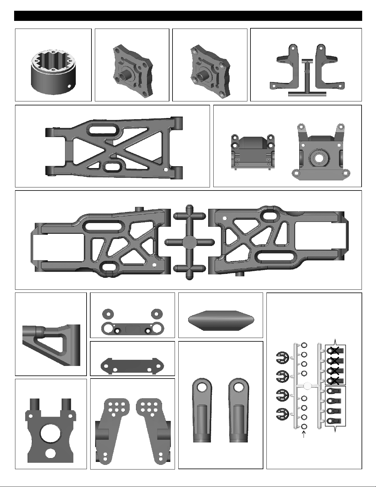
PLASTIC PARTS FOR USE
30751
DIFF. CASE
34063
REAR LOWER ARM
30657
FRONT LOWER ARM
30751
DIFF. CASE
FRONT & REAR
30761
DIFF. CASE
CENTER
40536
FRONT C HUB
30010
FRONT AND REAR GEAR BOX
36020
FRONT UPPER ARM
30201
CENTER DIFF. MOUNT
30351
REAR LOWER ARM HOLDER
30160
FRONT LOWER ARM HOLDER
36081
REAR WHEEL HUB
30240
BUMPER
40065
REAR UPPER ARM
PLASTIC ROD END
40643
SHOCK PLASTIC PARTS
40643
Shock Cap
Washer
40643
Shock Plastic
Ball End
(Long)
40643
Shock Plastic
Ball End
(Short)
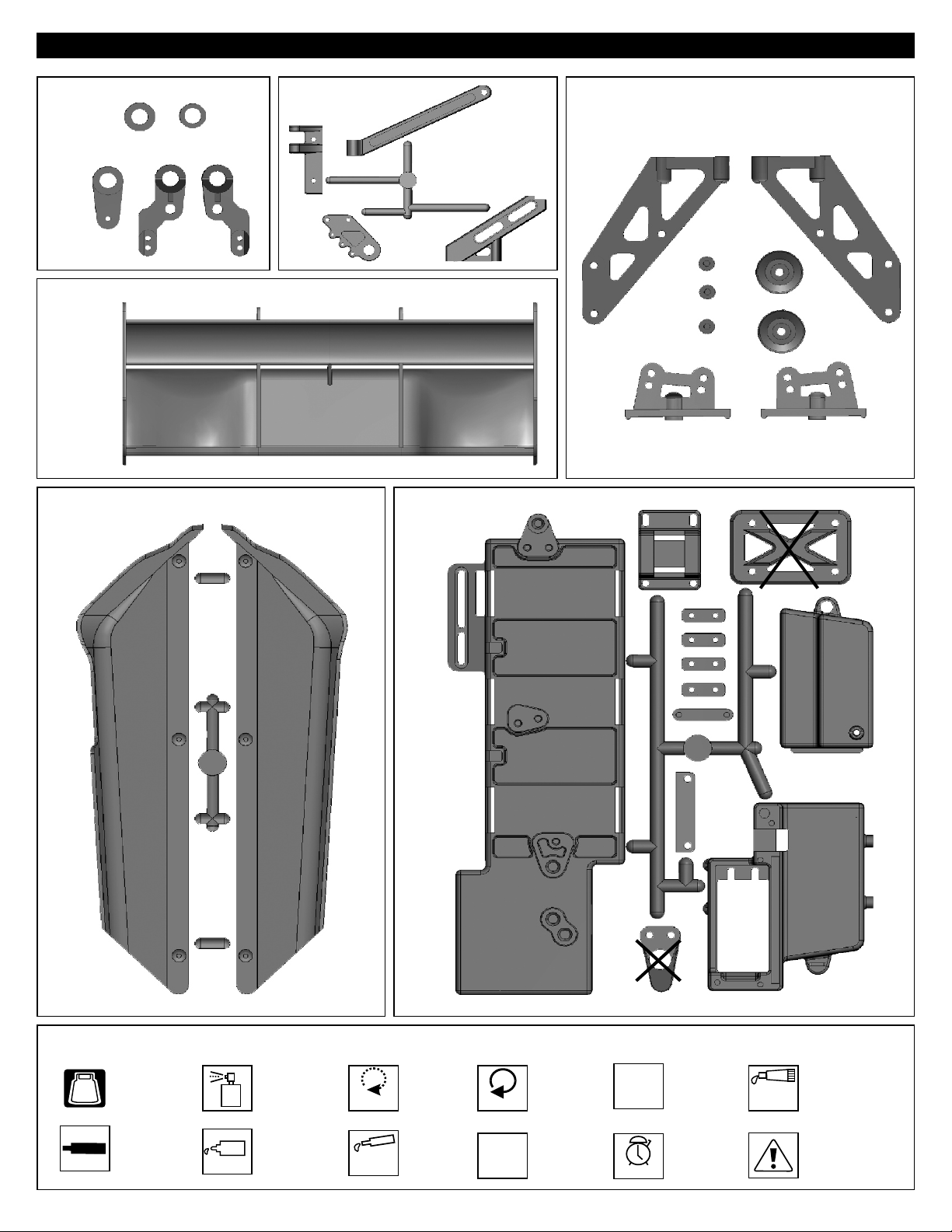
PLASTIC PARTS FOR USE
30674
SERVO SAVER
16015
WING
41033
STONE GUARD
30686
FRONT STIFFENER
30662BATTERY CASE
30270
WING STAY
SYMBOLS USED THROUGHOUT THE INSTRUCTION MANUAL
Degrease With
Motor Spray
Apply OilApply Screw
BAG
Screw
Cement
Parts Bag Used
Cement
Oil
Do Not
Over Tighten
Apply
Grease
Do Not
Over Tighten
Apply Lubricant
Tighten
1:1
Tighten
True-To-Scale
Ensure
Free
Movement
Time
Ensure Free
Movement
Contact
Adhesive
Contact Adhesive
Time Pay attention here

1
ASSEMBLY OF THE FRONT AND REAR DIFF.
Step 1
94034
4x4mm
Set Screw
30121
3x5mm Screw
94004
3x12mm
Hex Screw
30777
P5 O-Ring
30776
4x10mm Washer
30780
2x12.8mm Pin
.....x2
.....x8
.....x8
.....x4
.....x8
.....x4
30779
Step 3
Step 5
30769
30777
30751
30620
30773
30769
30901
30780
30776
Oil
4x4mm
30769
Notice the straight
holes are for the
front and rear only.
Step 2
30120
Build two differentials for front and rear.
30751
30777
Step 4
Apply diff. gear grease
to the differential, during
assembly.
Fill the diff. case to
approx 80% with grease.
Tighten the diff. screws
in this order.
30620
30901
Oil
30780
Tighten
3x12mm
30773
4mm Cross Pin
30121
3mm Tube
2
ASSEMBLY OF THE CENTER DIFF.
94034
4x4mm
Set Screw
94020
3x12mm
Flat Head Hex Screw
94004
3x12mm
Hex Screw
30777
P5 O-Ring
.....x4
.....x8
.....x1
.....x4
.....x4
.....x2
30779
Note: It is very important to remove
the 30776 washer if the gear
mesh is too tight.
*Push 3mm tubes into the
holes of the diff. case.
30121
30121
30911
30620
Step 1 Step 2
30769
Step 3
30777
30761
30773
30780
30769
4x4mm
30776
Oil
30769
Notice the tapered
holes are for the
center diff.
30777
1
3
30761
Apply diff. gear grease
to the differential, during
assembly.
Fill the diff. case to
approx 80% with grease.
30620
Step 4
4
2
30911
Oil
30780
Tighten
3x12mm
30776
4x10mm Washer
30780
2x12.8mm Pin
30773
4mm Cross Pin
.....x4
.....x2
.....x2
Step 5
3x12mm
30110
3mm
Tighten the diff. screws
in this order.
1
3
4
2

3
ASSEMBLY OF THE CENTER DIFF. MOTOR MOUNT
Note: The width of the
holes for front diff.
Mount.
94003
3x10mm
Hex Screw
94004
3x12mm
Hex Screw
4
ASSEMBLY OF THE FRONT GEAR CASE
.....x2
.....x2
Step 1 Step 2
94036
5x4mm
Set Screw
.....x1
30010
3x12mm
30653
3x10mm
30201
5x4mm
30630
C m
e
re
wSc
ent
Sc
em
C nt
30082
w
e
cr
S
t
en
e
C m
30675
er w
e
4x12mm
30673
94010
4x12mm
Hex Screw
.....x2
30630
30130
30630
6x13x5mm
Ball Bearing
5
ASSEMBLY OF THE FRONT GEAR CASE
.....x2
Apply
Grease
Step 1
94009
4x10mm
Hex Screw
94022
3x18mm
Flat Head Hex Screw
94029
4x25mm
Flat Head Hex Screw
41009
3x28mm
Cap Screw
.....x2
.....x2
.....x2
.....x2
4x10mm
3x18mm
30655
4x25mm
30010
Apply
Grease
Notice the direction.
41010
3x10mm
41010
Step 2
41009
30102
94003
3x10mm
Hex Screw
.....x1
94011
4x15mm
Hex Screw
.....x2
30160
4x16mm

6
ASSEMBLY OF THE KNUCKLE ARMS
Assemble both right and left side.
Step 1
94034
4x4mm
Set Screw
94042
4mm
Nylon Nut
40527
Knuckle Arm
Bushing
40528
King Pin Screw
36055
2.5x16.8mm Pin
7
ASSEMBLY OF THE FRONT SUSPENSION ARMS
36870
4x10mm
Set Screw
.....x2
.....x4
.....x4
.....x4
.....x2
.....x2
36053
Step 3
34053
40218
8x12x0.3mm Washer
Step 1 Step 2
.....x2
40520
8x12x0.3mm
36053
36055
30656
Step 2
40536
4x4mm
4mm
40528
4mm
ew cr
S
t
emen
C
Assemble both right and left side.
40527
40527
90020
2.5mm E-Ring
36850
7mm Ball
36861
5x35mm
Turnbuckle
36170
3x44.3mm Arm Shaft
8
ASSEMBLY OF THE FRONT SUSPENSION ARMS
94041
3mm Nylon Nut
94008
3x25mm
Hex Screw
90021
3mm E-Ring
.....x4
.....x2
.....x2
.....x2
.....x2
.....x2
.....x8
4x10mm
30657
2.5mm
36170
Step 1 Step 2
3mm
2.5mm
3mm
36020
1•1
Approx. 9.5mm
36861
36850
Assemble both right and left side.
3mm
3mm
36171
36690
36640
4x47mm Arm Shaft
36171
4x74.1mm Arm Shaft
.....x2
.....x2
3x25
36640
3mm
Insert the front drive shaft into
cap joint before assembly.

9
ASSEMBLY OF THE FRONT STABILIZER
Step 1 Step 2
94033
3x3mm
Set Screw
94035
3x8mm
Set Screw
94002
3x8mm
Hex Screw
.....x2
.....x2
.....x2
Assemble both right and left side.
3x3mm
94006
3x18mm
Hex Screw
94040
3x8x0.8mm
Washer
10
ASSEMBLY OF THE SERVO SAVER
94041
3mm Nylon Nut
94005
3x15mm
Hex Screw
36742
Servo Saver Bushing
36743
6mm E-Ring
40218
8x12x1mm Washer
.....x2
.....x2
.....x2
.....x2
.....x2
.....x4
.....x1
3x8x0.8mm
3x8mm
Step 1 Step 2 Step 3
8x12x1mm
3x8x0.8mm
30674
36741
30361
34027
36743
30674
36743
30674
30674
30361
36743
30674
36743
3x18mm
Makes two rods for left and right
hand-side
3x16mm
36742
30658
3mm
30341
40199
3x8mm
40199
30403
11
ASSEMBLY OF THE SERVO SAVER AND STEERING TIE-ROD
94003
3x10mm
Hex Screw
40038
7mm Ball
.....x3
.....x4
rew
30540
30380
Sc
em t
C en
Step 1 Step 2
3x10mm
e
Scr
C tem
34014
w
en
36700
40038
36790
Approx. 31mm
1•1
Make two steering rods
for left and right hand-side.
40038
36700

12
ASSEMBLY OF THE SERVO SAVER ONTO GEAR CASE
Step 1 Step 2
3x15mm
40039
94003
3x10mm
Hex Screw
.....x2
3x10mm
Screw
e
C
me
3x15mm
nt
40039
94021
3x15mm
Flat Head Hex Screw
40039
3mm
Tapered Washer(Alum.)
13
ASSEMBLY OF THE REAR GEAR CASE
.....x4
.....x4
Step 1
94036
5x4mm
Set Screw
.....x1
Apply
Grease
30630
30630
5x4mm
Screw
ment
Ce
30082
Screw
me
e
C
Step 2
3x15mm
nt
40039
30630
6x13x5mm
Ball Bearing
14
ASSEMBLY OF THE REAR GEAR CASE
.....x2
30130
Step 1 Step 2
94022
3x18mm
Flat Head Hex Screw
.....x2
3x18mm
94027
4x16mm
Flat Head Hex Screw
94029
4x25mm
Flat Head Hex Screw
.....x2
.....x2
4x25mm
30010
30010
30649
Apply
Grease
30351
4x16mm
30351

15
ASSEMBLY OF THE REAR GEAR CASE
Step 1 Step 2
41009
94019
3x10mm
Flat Head Hex Screw
94006
3x18mm
Hex Screw
94007
3x20mm
Hex Screw
41009
3x28mm
Cap Screw
16
ASSEMBLY OF THE WING STAY AND REAR WHEEL HUB
94036
5x4mm
Set Screw
94011
4x15mm
Hex Screw
90018
3x25mm
Cap Screw
.....x1
.....x2
.....x4
.....x2
.....x2
.....x2
.....x2
41010
3x10mm
41010
Step 1
3mm
4x15mm
34033
41009
3mm
3x20mm
3x18mm
Step 2
30270
36082
30270
36053
30270
30270
30270
30270
*Builds two rear wheel hubs for use.
36081
36055
30656
30270
3x20mm
3x18mm
94041
3mm Nylon Nut
36055
2.5x16.8mm
Pin
17
ASSEMBLY OF THE REAR WHEEL HUB AND UPPER ARM ROD
36870
4x10mm
Set Screw
94001
3x5mm
Hex Screw
34063
3x9.5x4mm
Plastic Washer
34055
3x42.6mm Arm Shaft
.....x2
.....x2
.....x4
.....x2
.....x2
.....x2
3x25mm
Step 1
4x10mm
4x15mm
34063
34063
34063
34055
3x5mm
Step 2
36850
36053
Assemble both right and left side.
40065
36861
36850
1:1
Approx. 18.9mm
5x4mm
40065

18
ASSEMBLY OF THE REAR LOW ARMS INTO GEAR BOX
Assemble both right and left side.
Step 1
94041
3mm Nylon Nut
90021
3mm E-Ring
94006
3x18mm
Hex Screw
94008
3x25mm
Hex Screw
19
ASSEMBLY OF THE REAR STABILIZER
.....x4
.....x4
.....x2
.....x2
3mm
Step 2
3x18mm
3mm
3x25mm
3mm
3mm
36171
34054
94002
3x8mm
Hex Screw
94040
3x8x0.8mm
Washer
20
ASSEMBLY OF THE REAR STABILIZER RODS
94033
3x3mm
Set Screw
94035
3x8mm
Set Screw
.....x2
.....x2
.....x2
.....x2
Makes two rods for left and right
hand-side
3x8x0.8mm
3x8mm
30341
3x8mm
3x8x0.8mm
40199
34027
Assemble both right and left side.
3x3mm
94006
3x18mm
Hex Screw
.....x2
40199
3x18mm
30403

21
ASSEMBLY OF THE FRONT GEAR CASE ONTO CHASSIS
94019
3x10mm
Flat Head Hex Screw
94023
3x25mm
Flat Head Hex Screw
94026
4x12mm
Flat Head Hex Screw
94027
4x16mm
Flat Head Hex Screw
22
ASSEMBLY OF THE CENTER DIFF. ONTO CHASSIS
.....x2
.....x2
.....x2
.....x4
30240
4x16mm
Insert drive shaft into cap
joint before assembly
center diff.
3x25mm
4x16mm
30676
4x12mm
3x10mm
94026
4x12mm
Flat Head Hex Screw
94027
4x16mm
Flat Head Hex Screw
.....x3
.....x2
36100 (90mm)
4x16mm
4x12mm

23
ASSEMBLY OF THE REAR GEAR CASE ONTO THE CHASSIS
Insert drive shaft into cap
joint before assembling
center diff.
94023
3x25mm
Flat Head Hex Screw
94027
4x16mm
Flat Head Hex Screw
.....x2
.....x4
36100 (86.5mm)
4x16mm
3x25mm
4x16mm
24
ASSEMBLY OF THE STONE GUARD
Assemble both right and left side.
41033
94019
3x10mm
Flat Head Hex Screw
.....x6
3x10mm
3x10mm
3x10mm

25
ASSEMBL OF THE REAR CENTER BRACEY
3x12mm
30686
30686
4x20mm
94042
4mm Nylon Nut
94004
3x12mm
Hex Screw
94012
4x20mm
Hex Screw
94027
4x16mm
Flat Head Hex Screw
26
ASSEMBLY OF THE MAGIC TAPE INTO BATTERY CASE
.....x2
.....x2
.....x1
.....x1
4mm
4x16mm
Step 1
Step 2
30662
30663

27
ASSEMBLY OF THE ELECTRIC SPEED CONTRTOL
Double side tape
28
ASSEMBLY OF THE BATTERY TRAY BRIDGE ONTO BATTERY CASE
3x8mm
30662
3x10mm
Electronic Speed Control
30693 90AMP ESC
94002
3x8mm
Hex Screw
94003
3x10mm
Hex Screw
29
ASSEMBLY OF THE ELECTRIC SPEED CONTROL WIRE INTO RADIO CASE
Step 1
.....x2
.....x2
30662
30662
Step 2

30
ASSEMBLY OF THE STEERING SERVO ONTO RADIO CASE
3x10mm
3x10mm
3x8x0.8mm
94003
3x10mm
Hex Screw
94040
3x8x0.8mm
Washer
31
ASSEMBLY OF THE SERVO WIRE INTO RADIO CASE
.....x4
30662
.....x4
3x8x0.8mm
Steering Servo
32
ASSEMBLY OF THE BATTERY CASE ONTO CHASSIS
94019
3x10mm
Flat Head Hex Screw
94026
4x12mm
Flat Head Hex Screw
94053
5x10mm
Flat Head Hex Screw
.....x3
.....x1
.....x2
4x12mm
5x10mm
3x10mm
3x10mm

33
ASSEMBLY OF THE RADIO CASE ONTO CHASSIS
94019
3x10mm
Flat Head Hex Screw
34
ASSEMBLY OF THE RECEIVER INTO RADIO CASE
Please carefully read the Receiver Instruction
Manuals before installation.
94002
3x8mm
Hex Screw
.....x4
*Plug in your speed controller
wire to CH2 and steering servo
wire to CH1 of your receiver.
.....x2
3x10mm
Receiver
3x10mm
Antenna Wire
40642
37410
30560
3x8mm
30662
30662
Do not cut or shorten antenna wire.
Step detail
Use a screwdriver to straighten the antenna wire so
it is easier to insert into antenna tube.
35
ASSEMBLY OF THE STEERING ROD ONTO STEERING SERVO
SAVOX
Sanwa/Airtronics
S J F
Choose the right servo horn adapter for your servo.
94004
3x12mm
Hex Screw
30411
6mm Ball Socket
JR
.....x2
.....x2
Futaba
HiTech
H
3x12mm
30401
30411
30661
30411
30401
38280(3x36mm)
3x12mm
30661
Approx. 19mm
13

36
MOTOR INSTALL
Electric Motor
(30694)
94034
4x4mm
Set Screw
37
MOTOR INSTALL
94038
3x12mm
Cap Screw
.....x1
.....x2
4x4mm
30665-(14T)
3x12mm
Do Not
Over Tighten
Step detail
*Approx. 20mm
94040
3x8x0.8mm
Washer
38
ADJUST MOTOR AND SPUR GEAR MAINTENANCE
.....x2
PUSH
Adjust the motor position to get proper gear mesh.
To get a perfect gear mesh , place a piece of notebook paper
between the gears and tighten the motor mount screws.
The spur gear will strip if the gear mesh is wrong.
Tighten
Tighten
3x8x0.8mm
30694
BRUSHLESS MOTOR
1900KV
EXTREMELY IMPORTANT
Notebook paper
Insert a piece of notebook paper between
spur gear and pinion gear to make correct
gear mesh.
Tighten the 3x12mm screw
temporary.
14

39
ASSEMBLY OF THE SHOCKS
40060
40060
2.6x6x0.5mm
41011
2.6x6x0.5mm
40054 (SHORT) 40055 (LONG)
2.6x6x0.5mm
2.6x6x0.5mm
41011
Step detail
Hold the shock rod at top of exposed
thread with side cutting needle nosed pliers.
Be careful not to damage the shock
shaft.
Assemble both left and right sides.
Do Not
Over Tighten
Use tools to tighten as shown.
40060
2.6mm
Nylon Nut
94059
2.6x6x0.5mm
Washer
40
ASSEMBLY OF THE SHOCKS
41012
1mm Washer
41012
2mm Washer
41012
3.5mm O-Ring
.....x2
.....x4
.....x4
.....x4
.....x8
FRONT SHOCK
Oil
Oil
REAR SHOCK
41008
41012(2mm)
41012
41012(1mm)
41012
40113
41003 (SHORT)
Step detail Step detail Step detail
41008
41012(2mm)
Oil
Oil
41012
41012(1mm)
41012
40113
41004 (LONG)
Assemble both left and right sides.
40113
P10 O-RING
41
ASSEMBLY OF THE SHOCKS
Oil
.....x4
(SHORT)
(SHORT)
REAR SHOCKFRONT SHOCK
Assemble both left and right sides.
(LONG)
Oil
Do not push the shock
shaft straight down;
O-ring can be damaged.
(LONG)
REAR SHOCKFRONT SHOCK
EXTREMELY IMPORTANT
Slowly twist the shock
shaft down to the
bottom.
15

42
ASSEMBLY OF THE SHOCKS
Assemble both left and right sides.
41007
P10 O-RING
43
ASSEMBLY OF THE SHOCKS
Step detail
.....x4
28mm
37.5mm
41007
Oil
Fit the o-ring into groove before
assembly.
40643
Do Not
Over Tighten
41006
30403
Step 2Step 1
Oil
Oil
Step detail
TOP
FRONT SHOCK
40643
Do Not
Over Tighten
30403
REAR SHOCK
Assemble both left and right sides.
Step detail
Attention distance.
30403
6mm Ball
44
SETTING THE SHOCK REBOUND TO 100% (HIGH REBOUND)
Step 1 Step 2
H
O K OILS
C
.....x4
3~5x
UP & DOWN
REAR SHOCKFRONT SHOCK
Step 3 Step 4
Leave the filled shock vertically for several
minutes with the shock shaft fully extended.
Time
The remaining air bubbles will release.
Step detail
41013
41005
14mm
Use tools to tighten as shown be
careful not to scratch the shock shaft.
Assemble both left and right sides.
TIGHTENED HALF WAY 50% TIGHTENED 100%
Step 5
Step 6
16

45
SETTING THE SHOCK REBOUND TO 50% & 0%
(MEDIUM REBOUND & LOW REBOUND)
TIGHTENED HALF WAY 50%
Step 1 Step 2
46
ASSEMBLY OF THE SHOCKS SPRING
Step 2 Step 3
50%
TIGHTENED 100%
Step 3 Step 1 Step 2 Step 3
50%
TIGHTENED HALF WAY 50% TIGHTENED 100%
Step 1 Step 2
Step 1
47
ASSEMBLY OF THE SHOCKS
40058
Cut 7mm
INTO THE SHOCK STAY
40643
94041
3mm Nylon Nut
.....x4
41015(SHORT)
41008
41015(LONG)
40058
REAR SHOCKFRONT SHOCK
41008
40643
94040
3x8x0.8mm
Washer
94007
3x20mm
Hex Screw
.....x4
.....x4
3mm
3x8x0.8mm
3x20mm
3x20mm
FRONT SHOCK REAR SHOCK
17
3mm
3x8x0.8mm

48
ASSEMBLY OF THE TIRES AND WHEELS
Step 1
Make four tires that are the same.
80025
IN
ST
G
AN
L E U
T
Step 2
Step detail
86056
49
ASSEMBLY OF THE TIRE ONTO THE FRONT
KNUCKLE AND REAR HUB
INST
G
A
L
NT
UE
Step 3
Use CA or “ Instant glue " and draw a round the
rim where it attaches the tire . When it is dry
glue the other side of the rim.
Repeat the step and ensure the rim and tire are
fully glued.
Agglutination place
Assemble both left and right sides.
40550
Wheel Nut
50
ASSEMBLY OF THE WING
94004
3x12mm
Hex Screw
.....x4
.....x2
26.5mm
26.5mm
Drill two 7mm holes for mounting.
16015 WHITE
16016 YELLOW
16017 RED
16018 BLACK
16019 ORANGE
40550
To tighten the Wheel Nut you can also
use 17mm Wheel Nut Tool.(10801)
3x12mm
30270
18

51
BATTERY INSTALL
Follow the manual instruction provided by ESC
manufacturer to install the wire.
52
MAKING HOLES AND CUTTING ON THE BODY SHELL
If use hard case battery , make a hole as picture shown.
15mm
8mm
Step 1 Step 2
Make 6mm hole
53
WASH THE INSIDE OF THE BODY SHELL
Step 1 Step 2
Body Reamet (not included)
10806 BLACK
10807 BLUE
Make 7.5mm holes on the body, Body Mount
as shown.
31143
For electric speed control cooling hole.
Cut the body shelll as shown.
Wash the inside of the body shell with mild detergent,
and then rinse and dry thoroughly.

54
PAINTING BODY SHELL
Mask the windows on the inside with masking tape.
55
PAINTING BODY SHELL
Paint the body with polycarbonate spray paints.
56
MOUNTING THE BODY SHELL
31159
31159
S
p
ra
y
Pa
i
n
t
When the paint is dry, remove the masking
tape.
When you have finished painting, peel off
the external protective films.

ULTRA LX2 ELECTRIC POWERED
EXPLODED VIEW
30540
41010
30655
30102
36740
36741
30361
30658
36742
30010
36743
36740
30380
30686
36740
30361
36742
36850
36700
36790
36740
40038
36700
40039
30151
30151
30689
30082
36171
30240
B-B
36171
34027
30403
30010
30160
A-A
30341
40528
40527
30657
30130
36850
40528
40527
30656
40520
40199
30403
36020
36861
36690
36170
34053
40536
C-C
40550

30560
40642
30662
38280(3x36mm)
30661
30401
30401
30411
30411
30661
37410
41033
30662
36100 (90mm)
30662
30662
30662
30653
30665-(14T)
36100 (86.5mm)
30675
E-E
30201
30676
E-E
30911
30110
30769
30620
30769
30761
30777
30777
30761
30620
30769
30773
30911
30662
30663
30662

30649
41010
30270
36171
A-A
30686
30901
34033
30082
30761
30751
30120
30121
30769
30779
30686
36171
36850
30769
40065
30773
30121
30130
30010
A-A
30769
36861
36850
30901
30403
D-D
30270
30351
34027
30341
30010
34054
40199
34063
34055
FRONT SHOCK ASSEMBLY
B-B
41015
41008
30403
41007
40643
30403
40113
41006
40102
41008
36082
36081
30270
30351
40058
41012
16015
41003
40102
41011
40054
41013
C-C
40550
30656
40643
41005
40060
C-C
B-B
80025
86056
REAR SHOCK ASSMEBLY
B-B
D-D
41015
41008
40113
30403
41008
41006
41007
40643
41012
40058
41004
40055
40643
41005
41013
41011
40060

Positive
+
SETTING GUIDE
FRONT CAMBER ANGLE SETTING REAR CAMBER ANGLE SETTING
Positive
Negative
-
-
+
Negative
+
-
-
+
Turnbuckle
Place the model car on flat surface. Raise the chassis to its maximum clearance
before the wheels leave the ground.
Adjust the length of the front and rear upper arms so that the wheels are vertical to the
ground.
Adjust the camber angle by turning the turnbuckle rod on the upper arms clockwise or counter-clockwise.
(We suggest to use zero degree for the front and 1.5 degree for the rear.) negative
FRONT TOE-IN AND TOE-OUT SETTING
NEUTRAL POSITION
TOE-OUT TOE-OUT
TOE-IN
Steering Rod
Turnbuckle
Different shock positions will result in firmer or softer response of the
suspension system.
Install the shock in an inward angle will cause softer rebound. Softer or firmer
suspension system will lead to different steering response.
Adjust the shock angle positions according to track conditions.
FRONT SHOCK ANGLE SETTING
Soft
1 2 3
Firm
Adjust the length of front steering rod to
change the toe angle.
Making the tie rod longer will make front
tires toed in.
Response will be slower and may over steer.
Making the tie rod shorter will make front
tires toed out.
Response will be quicker and may under steer.
Firm front suspension, less steering.
Soft front suspension, more steering.
REAR SHOCK ANGLE SETTING
Firm rear suspension, over steering.
Soft rear suspension, under steering.
Soft
Soft
Soft
1 2 3
12
3
Firm
Firm
12
Firm

OFNA DESCRIPTIONS RETAIL OFNA DESCRIPTIONS RETAIL
16015 HI FORCE WING, 1/8 WHITE 15.95 34055 PINS, LOWER REAR ARMS 3x42.6mm 15.95
30010 GEARBOX, ULTRA SERIES 14.95 34063 FRONT & REAR LOWER ARMS 13.95
30082 CAP JOINTS, 6mm, 2 PCS. 9.95 36020 FRONT UPPER ARMS, 2 PCS. 5.95
30102 BODY MOUNT POSTS, 2 PCS. 0.95 36053 BEARING, 8x16mm, PAIR 12.95
30110 SPUR GEAR,(NYLON) ULTRA 7.95 36055 PIN, 2.5x17mm, HEX HUBS, 4PCS 3.95
30120 LARGE BEVEL GEAR,44T 10.95 36055 PIN, 2.5x17mm, HEX HUBS, 4PCS 3.95
30121 BEVEL MOUNTING HARDWARE,MISC 1.95 36081 REAR UP-RIGHT (8mm BEARING) PR 12.95
30130 PINION GEAR,14T ULTRA 14.95 36082 REAR AXLES, 8mm PAIR 10.95
30160 FRONT PLATE, ARM PIN HOLDERS 4.95 36100 CENTER DOGBONES,SET 86.5,90mm 16.95
30201 CENTER, DIFF MOUNT, NEW TYPE 13.95 36170 ARM PINS, 3mm 4PCS LX1 7.95
30240 FRONT BUMPER, ULTRA CHASSIS 7.95 36171 ARM PIN 4x74.1mm LX1 & X2T 5.95
30270 WING STAY,REAR,PLASTIC 13.95 36640 ARM SHAFT, 4mm, SHORT, 2PCS 9.95
30341 BALL END WITH COLLAR, 6mm 3.95 36700 STEERING BALL END, 7mm, 8PCS. 6.95
30351 REAR ARM HOLDER 3PCS 3.95 36741 SPRING, SERVO SAVER NEW HARD 3.95
30361 SERVO SAVER SHAFT 5.95 36742 BUSHING, SERVO SAVER 1.95
30380 SERVO SAVER POSTS, 2 PCS. 4.95 36743 E-CLIP, 6MM SERVO SAVER 2.95
30401 STEERING ENDS, PLASTIC 6 PCS. 2.95 36760 FRONT PLATE JOINT 9.95
30403 6mm BALL, STEEL (NO COLLAR) 4.95 36790 4x46MMTURNBUCKLES,4PCS. 10.95
30411 6mm BALLS w/COLLAR,STEERING 6P 4.95 36850 7mm BALL, 6 PCS. 3.95
30620 BEARING KIT, 7x19mm, 6 PCS. 29.95 36861 5x40mm TURNBUCKLES, 2 PCS BLK 6.95
30630 BEARING KIT, 6x13mm 12PCS. 59.95 37410 BODY CLIPS, 10 PCS. SMALL JL10 3.95
30649 SHOCK TOWER REAR LX1 H.C. 11.95 38280 TURNBUCKLES, 3X36MM 2PCS 5.95
30653 CENTER TOP PLATE LX1 H.C. 6.95 40038 BALLS, 7MM 4PCS. 9.95
30656 WHEEL HUB, LX1, PICCO 9.5 H.C. 11.95 40039 TAPPER CONE WASHERS,3MM 3.95
30657 LOWER ARM,FRONT, LX1 13.95 40053 SHOCK BODY REAR,THREADED,2PCS 59.95
30658 SERVO SAVER CONNECTOR H.C. LX1 6.95 40054 SHOCK SHAFTS,3.5m FR 13/16mm 7.95
30661 SERVO HORN HEAVY DUTY BLACK 4.95 40055 SHOCK SHAFTS,3.5m RR 13/16mm 7.95
30662 BATTERY CASE,RX BOX LX-1e 19.95 40058 SHOCK BOOTS,SILICON 9.95
30663 BATTERY VELCRO STRAPS LX-1e 9.95 40060 SHOCK PISTON LOCKNUT,2.5mm,4PC 4.95
30665 PINION 14T 5MM SHAFT 12.95 40065 BALL ENDS, PLASTIC, REAR UPPER 4.95
30673 FRONT ARM HOLDER,H.C. LX-1 12.95 40113 O-RING P-10 FOR X1-CR,9.5 SHCK 1.95
30674 SERVO SAVER PLASTIC SET LX-1 7.95 40199 BALL END,STEERING,PLASTIC,6mm 7.95
30675 MOTOR MOUNT,CNC, LX-1e 29.95 40520 KNUCKLE ARM, L & R LX-2 19.95
30676 CHASSIS H.C. LX-1e 89.95 40527 KNUCKLE ARM BUSHING LX-2 4.95
30686 CENTER BRACE LX-2 PLASTIC 9.95 40528 KING PIN SCREW LX-2,X1X,NEXX8 1.95
30693 SPEED CONTROL 90A LX2 RTR 219.95 40536 FRONT C HUB LX-2,X1X,X2,NEXX8 11.95
30694 BRUSHLESS MOTOR 1900KV 5MM SHT 119.95 40550 WHEEL NUT 17mm LX-2 4.95
30751 CASE, DIFF (K), FRONT or REAR 9.95 40642 ANTENNA , FIXING NUT 2.95
30761 CASE, DIFF CASE (K), CENTER 9.95 40643 PLASTIC SHOCK PARTS,13/16mmLX2 9.95
30769 DIFF GEAR,SILVER BEVEL,SET 4mm 14.95 41003 SHOCK BODY FRONT 16MM PAIR 29.95
30773 CROSS PIN AXLES, 4mm STEEL 3.95 41004 SHOCK BODY REAR 16MM PAIR 29.95
30776 WASHER, 4x10x0.2mm 4PCS. 1.95 41005 SHOCK CAP 16MM 4PCS. 22.95
30777 SEAL, O-RING DIFF CASE 3.95 41006 SHOCK SPRING ADJ. 16MM 4PCS. 14.95
30779 MISC. PARTS, ULTRA DIFF 9.95 41007 O-RING 19x1.5MM 16MM 4PCS. 4.95
30780 PINS, 2X12.8mm FOR DIF 2PCS 3.95 41008 PLASTIC SHOCK PARTS 16MM SET 12.95
30901 CAP JOINT W/SHAFT F/R DIFF 11.95 41009 CAP SCREWS 3X28MM 4PCS. 2.95
30911 CAP JOINT W/SHAFT, BRAKE 11.95 41010 SHOCK BALL END POST LONG 4PCS 11.95
31143 BODY, CLEAR ULTRA LX2e 39.95 41011 SHOCK PISTON 16MM 8PCS. 10.95
31158 BODY, LX2e PRINTED RTR 55.95 41012 REPAIR KIT FOR 16MM SHOCK 9.95
31159 BODY CLIPS, CHROME 4.95 41013 PRESSURE TOP ORANGE 16MM 4PCS. 7.95
34014 BRACE, FRONT CHASSIC,ULTRACOMP 3.95 41022 SPRING .58 REAR 16MM WHITE 9.95
34027 ANTI-ROLL BAR KIT, U.COMP,LX1 3.95 41033 STONE GUARDS X2T 15.95
34054 SHAFT, REAR DOG BONE 93mm PR. 15.95 80025 TIRES, TRIAD 1/8 BUGGY W/FOAM 24.95
86056 17mm TrueLITES DISH, WHT 6PACK 19.95
34301 ULTRA LX2e RTR PARTS LIST

OFNA DESCRIPTIONS RETAIL
10231 DIFF OIL,SILICON 1000 WT 8.95
10232 DIFF OIL,SILICON 3000 WT 8.95
10233 DIFF OIL,SILICON 5000 WT 8.95
10234 DIFF OIL,SILICON 7000 WT 8.95
10235 DIFF OIL,SILICON 10,000 WT 9.95
10236 DIFF OIL,SILICON 30,000 WT 9.95
10237 DIFF OIL,SILICON 50,000 WT 9.95
10238 DIFF OIL,SILICON 120,000 WT 9.95
10239 CA TIRE GLUE,Rubber to Plastic 5.95
10772 SERVO HORN,CNC,23T AIRTRONICS 10.95
10774 SERVO HORN,CNC,24T HITEC 10.95
10776 SERVO HORN,CNC,25T FUTABA 10.95
10994 SERRATED LOK NUT,17mm 1/8TH 4P 15.95
16016 HI FORCE WING, 1/8 YELLOW 15.95
16017 HI FORCE WING, 1/8 RED 15.95
16018 HI FORCE WING, 1/8 BLACK 15.95
16019 HI FORCE WING, 1/8 ORANGE 15.95
30774 CROSS PIN AXLES, 4mm ALUM 6PCS 9.95
33991 PCR REAR SHOCK TOWER ULTRA 24.95
33995 PCR STEERING LINK PLATE ULTRA 14.95
33996 PCR UPPER PLATE, FRONT DIFF UL 15.95
33997 PCR CENTER DIFF. TOP PLATE ULT 15.95
41014 SPRING 16MM SUPER SOFT YEL SET 17.95
41016 SPRING 16MM BUGGY SILVER SET 17.95
41017 SPRING 16MM HARD GRAY SET 17.95
41018 SPRING 16MM TRUGGY BLUE SET 17.95
41020 SHOCK BALL END POST L.W. LONG 14.95
41021 SPRING .52 REAR 16MM YELLOW 9.95
41023 SPRING .59 REAR 16MM BLUE 9.95
41024 SPRING .60 REAR 16MM SILVER 9.95
41025 SPRING .64 REAR 16MM GRAY 9.95
41026 SPRING .66 FRONT 16MM YELLOW 9.95
41028 SPRING .71 FRONT 16MM BLUE 9.95
41029 SPRING .74 FRONT 16MM SILVER 9.95
41030 SPRING .88 FRONT 16MM GRAY 9.95
41116 CNC ALUM. BALLS SET HARDCOATED 24.95
40570 STEERING KNUCKLE CNC H.C. 99.95
86057 17mm TrueLITES DISH, YEL 6PACK 19.95
86058 17mm TrueLITES DISH, ORG 6PACK 19.95
34301 ULTRA LX2e OPTION PARTS

TO: OFNA TECHNICAL SUPPORT
7 VANDERBILT, IRVINE, CA 92618
TODAY’S DATE: month________day______
1. Print out form.
2. Fill out the form completely.
3. Make a copy of purchase receipt. All replacements/repairs will not be processed,
unless accompanied by proof that item(s) was purchased in the last 30 days.
4. Call OFNA technical support at (949)586-2910 for assistance or fax (949) 583-9272
1. Your name
____________________________
2. Your address:
____________________________
6. Name of kit / part (on tag or end of box)
_____________________________
7. Kit/part number (on tag or end of box)
_____________________________
8. Purchased from (store name)
____________________________
3. Your Phone Number
(_____)______________________
_____________________________
a. Store phone: (_____) _________
b. _____Item was a gift?
4. Your e-mail address:
____________________________
9. If a part is missing form the kit, circle
the appropriate answers:
5. Summary of your problem (check lines):
a______part(s) is missing from my kit
b______part(s) seems to be defective
c______other problem
a. Yes / No: Is kit box damaged?
b. Yes / No: Factory Seal sticker was secure.
c. Yes / No: I am the original owner.
d. Yes / No: I have contacted the dealer first.
10. Describe your issue fully and include any part numbers:
____________________________________________________________
____________________________________________________________
____________________________________________________________
____________________________________________________________
____________________________________________________________
____________________________________________________________
Failure to fill out this form completely will cause a delay in processing!
11. Affix proof of purchase on second page. All replacement / repairs will not be processed
unless accompanied by proof that item(s) was purchased in the last 30 days.
A. If you lost the store receipt, ask the store if they will give you a new one.
B. We do not accepted the following as a substitute: Hand written receipts, ebay transaction numbers/forms or
credit card statements.
12. Send in form with your defective product, as instructed to do by the Ofna
technician,(Name)_________________ you spoke to. (949)586-2910 fax (949) 583-9272
Can’t find Proof of Purchase?


OWNER’S REGISTRATION CARD
OFNA Racing congratulates you on your purchase of our fine OFNA Product. With proper maintenance and handling this kit will provide many hours of enjoyment.
The registration card should be filled out and mailed to OFNA Racing within 10 days of purchase date.
IMPORTANT!
Please print or type, filling in the information listed below and mail immediately
MAIL TO:
OFNA RACING
7 VANDERBILT
IRVINE, CA. 92618
TEL: (949) 586-2910
Write in Your Model Name and Part Number
REGISTRATION CARD
RACER’S NAME TEL:( )
ADDRESS
CITY STATE ZIP
DEALER’S NAME TEL: ( )
ADDRESS
CITY STATE ZIP
OFNA
7 Vanderbilt
Irvine, Ca. 92618

 Loading...