

OFNA Racing Ultra LX 1e User Manual

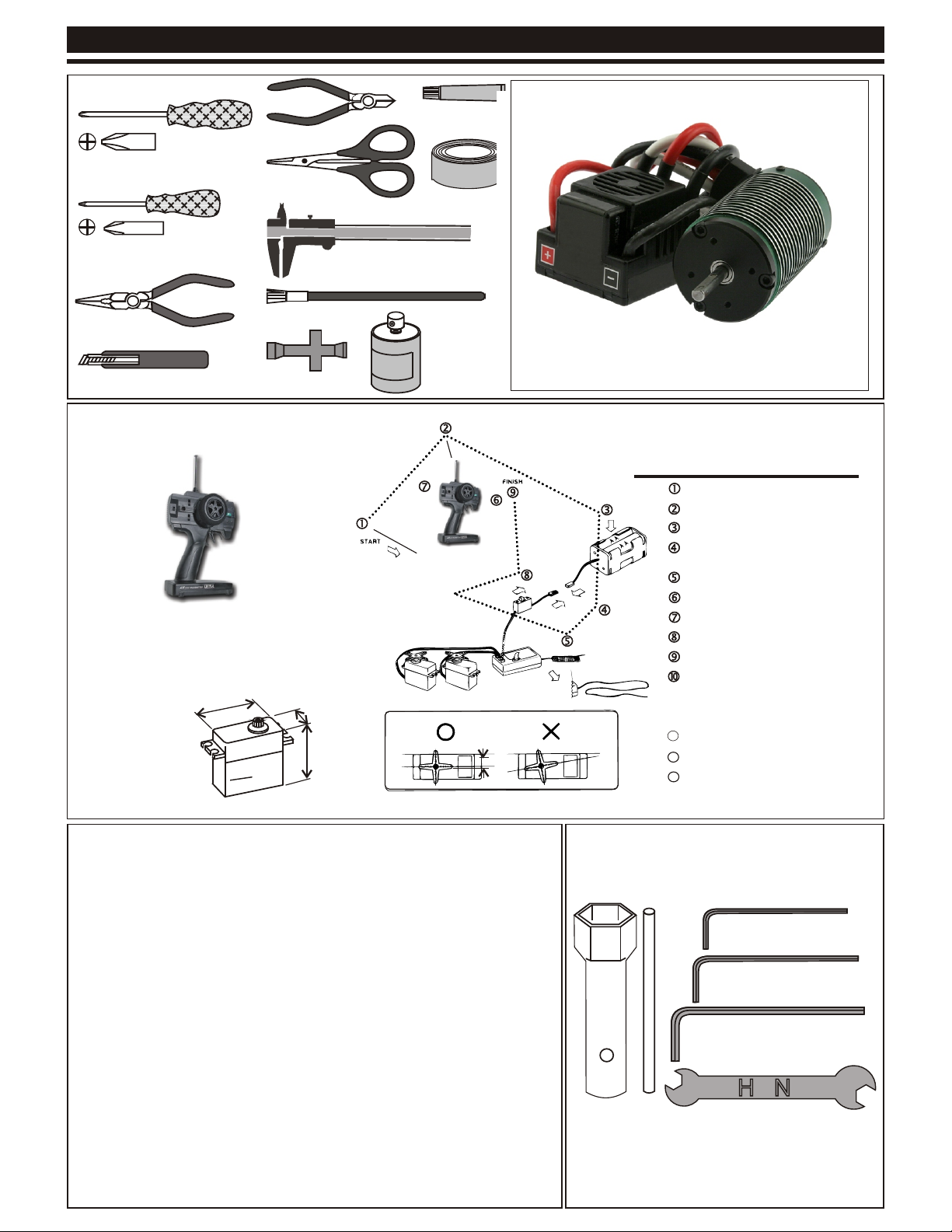
REQUIRED FOR OPERATION
TOOLS NOT INCLUDED IN THE KIT
Cutter
Phillips Type Screw Drivers ( L )
Curved Scissors
Phillips Type Screw Drivers ( S )
Needle Nosed Pliers
Knife
Precision Caliper
Brush
Cross Wrench
RADIO CONTROL UNIT
(NOT INCLUDED)
Note: Carefully read the instruction manual of your
2 channel radio controller before using.
SUITABLE SERVO SIZE
m
m
1
mm-4
36
15mm - 21mm
29mm - 42mm
CA Glue
Masking Tape
Spray Paints
NOT INCLUDED
MAMBA MONSTER 1/8 ESC WITH
2650KV BRUSHLESS MOTOR
Radio must be set at neutral position
before installing in the kit.
SEQUENCE TO SET NEUTRAL
Install AA batteries in Radio.
Extend the antenna.(Transmitter)
Install batteries into Car receiver .
After installing the battery, connect the
battery box.
Extend the antenna. (Receiver)
Set the trim-lever at center.
Turn on the switch. (Transmitter)
Turn on the switch. (Receiver)
Make sure the servos are in command.
When the operation stick is in neutral,
servo horns must be in neutral as will.
*Adjustment can be made by re installing the servo horn.
Turn off the switch. (Receiver)
111111
12
Turn off the switch. (Transmitter)
13
Retract the antenna. (Transmitter)
INCLUDED IN THE KIT
17mm Wheel
Nut Wrench
4mm'5mm Allen Wrench
1.5mm Allen Wrench
2mm Allen Wrench
2.5mm Allen Wrench

MUST READ THIS BEFORE RUNNING
Running a nitro kit is fun and easy, but to make this a safe • Clean oil and dirt from chassis with a degreaser like
and good experience you must observe a few rules. This
kit is extremely fast, easily over 40MPH, and can seriously
injure someone if you are not careful.
Where to run car?
• Any running area you choose must be dry. Do not run
car near any water or wet dirt.
• Do not run on public streets. It is very easy to have the
car run over or damaged by hitting the curb.
• Do not operate car in tight confined places. The car is
very fast and will easily hit something.
• Do not run near people or animals.
and will too easily hit someone.
• Due to noise, you will want to consider the surrounding
area when operating the car.
• Do not operate the car at night. You will not be able to
drive it without hitting something.
• Do not operate the car indoors. Engine exhaust is not
healthy.
Glow Fuel
• Glow fuel is poisonous!
• Glow fuel is flammable!
• Do not leave in fuel bottle with lid off at any time. label for additional precautions.
• Do not use any fuel other than glow fuel in this engine.
First Time Starting the Engine
Caution! When starting engine make sure the following is
observed. • Always turn off the car BEFORE turning off radio.
• Set engine Master needle to 3 turns (rich setting)
• Do not do this alone, get an experienced friend to help at • DAMAGE DUE CAR RUN AWAY IS NOT A WARRANTY
first. ISSUE.
• Fill fuel tank, try not to spill fuel. Do not spill fuel on
receiver
• Hold car off the ground, so it will not runaway when first
starts
• Turn on Radio and check the linkage before starting
engine.
• Turn on car receiver battery switch.
• Always have an air filter on the carburetor to keep dirt
out of engine.
The car is very fast
Simple Green.
Precautions
• This kit is not a toy. Always run car with a second
person as a spotter and pitman.
• Hot Parts - The pipe, manifold, engine and head are very
hot and will cause burns.
• Rotating Parts - Keep hands away from the drive train,
wheels, and engine when engine is running.
• Radio - Check batteries life before running the car. If
radio does not have full control of the car with steering
and/or throttle/brake do not run until corrected. Failure to
correct this will result in possible injury and damage to the
car or property.
• Glow fuel - Do not leave the glow fuel unattended with
the lid off. Fuel contains Methanol and Nitro Methane
both are flammable and poisonous.
•Store fuel in cool ventilated location. Refer the glow fuel
• Car Fuel tank - Never store fuel in car tank, it will ruin the
engine if left in tank.
Engine Break-in
• See Engine Page.
Emergency Stopping Engine When Running
• Remove air filter and cover carb. intake.
• Squeeze fuel line and hold until engine stops.
• With a rag, cover exhaust outlet.
Storing Car After Running
• Remove fuel from tank and fuel lines
• Turn off radio in car
• Put a few drops of after run in engine to keep it from
rusting.
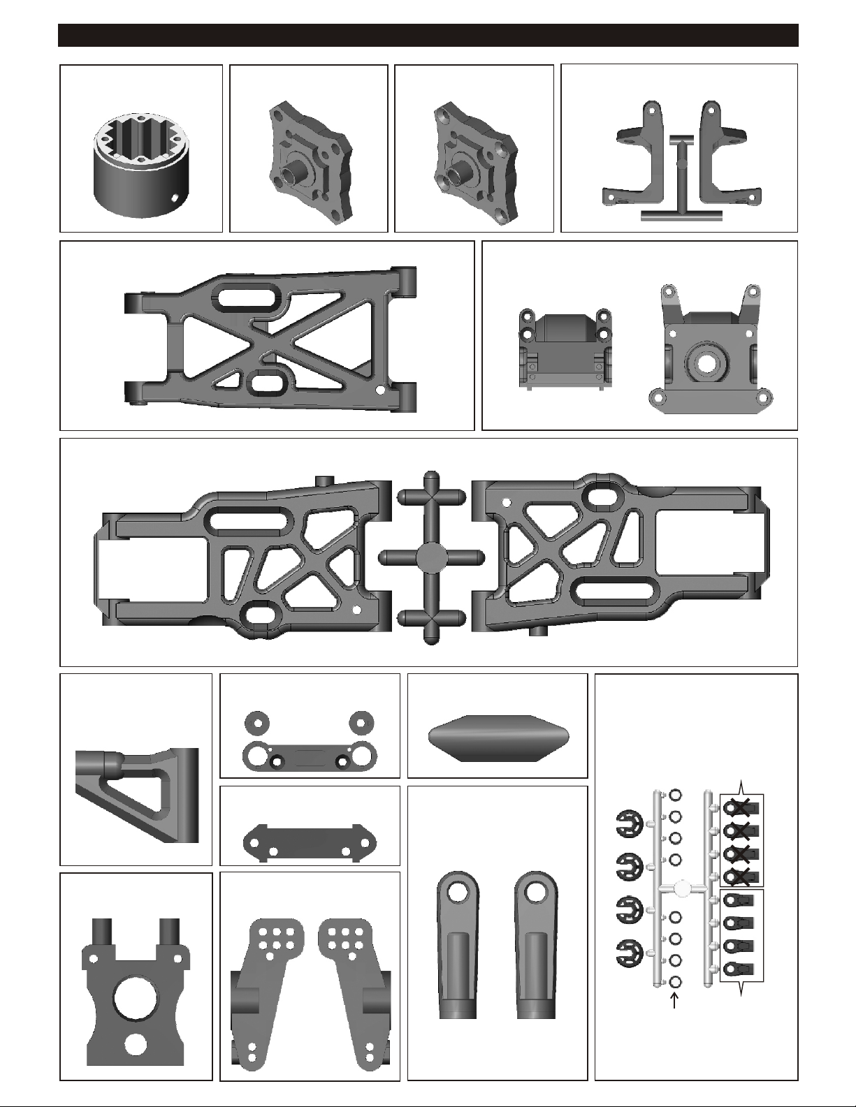
PLASTIC PARTS FOR USE
30751
DIFF. CASE
34063
REAR LOWER ARM
36011
FRONT LOWER ARM
30751
DIFF. CASE
30761
DIFF. CASE
40536
FRONT C HUB
30010
FRONT AND REAR GEAR BOX
36020
FRONT UPPER ARM
30201
CENTER DIFF. MOUNT
30351
REAR LOWER ARM HOLDER
30160
FRONT LOWER ARM HOLDER
36081
REAR WHEEL HUB
30240
BUMPER
40065
REAR UPPER ARM
PLASTIC ROD END
40643
SHOCK PLASTIC PARTS
40643
Shock Cap
Washer
40643
Shock Plastic
Ball End
(Long)
40643
Shock Plastic
Ball End
(Short)
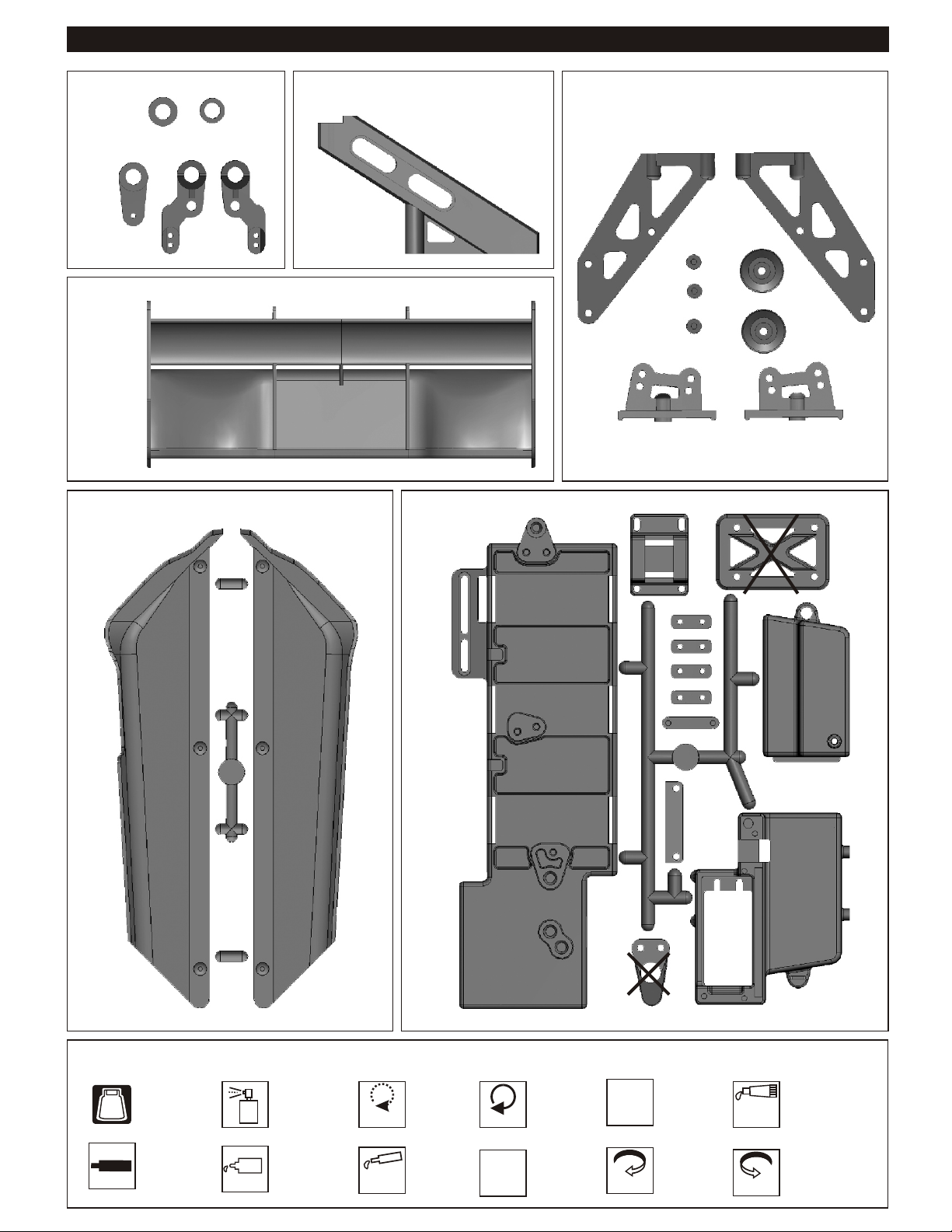
PLASTIC PARTS FOR USE
30674
SERVO SAVER
16016
WING
41033
STONE GUARD
40019
FRONT STIFFENER
30662
BATTERY CASE
30270
WING STAY
SYMBOLS USED THROUGHOUT THE INSTRUCTION MANUAL
Degrease With
Motor Spray
Apply OilApply Screw
BAG
C
c
met
e n
w S re
Parts Bag Used
Cement
Oil
Do Not
Over Tighten
Apply
Grease
Do Not
Over Tighten
Apply Lubricant
Tighten
1:1
Tighten
True-To-Scale
Ensure
Free
Movement
Rotate
Direction
Ensure Free
Movement
Clockwise
Rotation
Contact
Adhesive
Rotate
Direction
Contact Adhesive
Anti-clockwise
Rotation
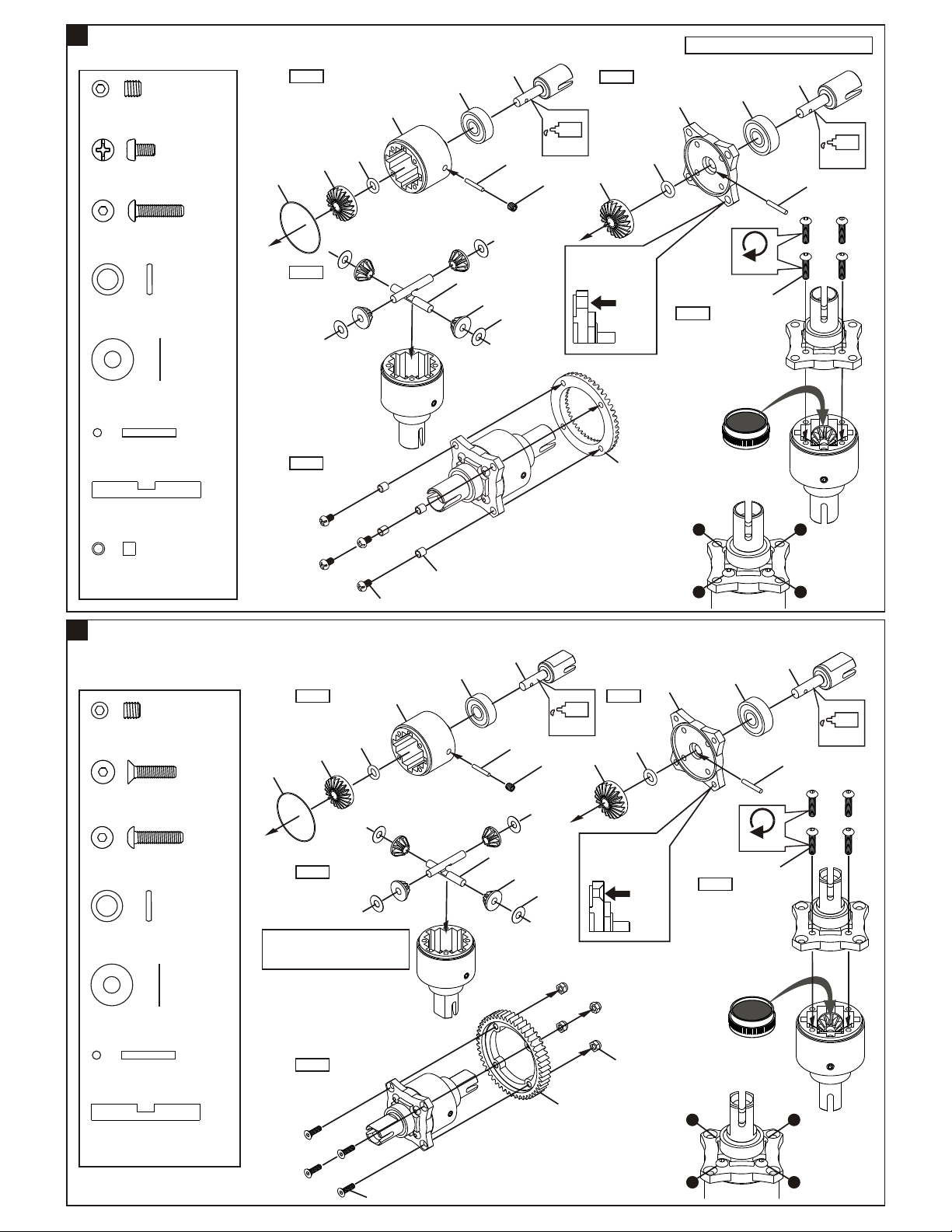
1
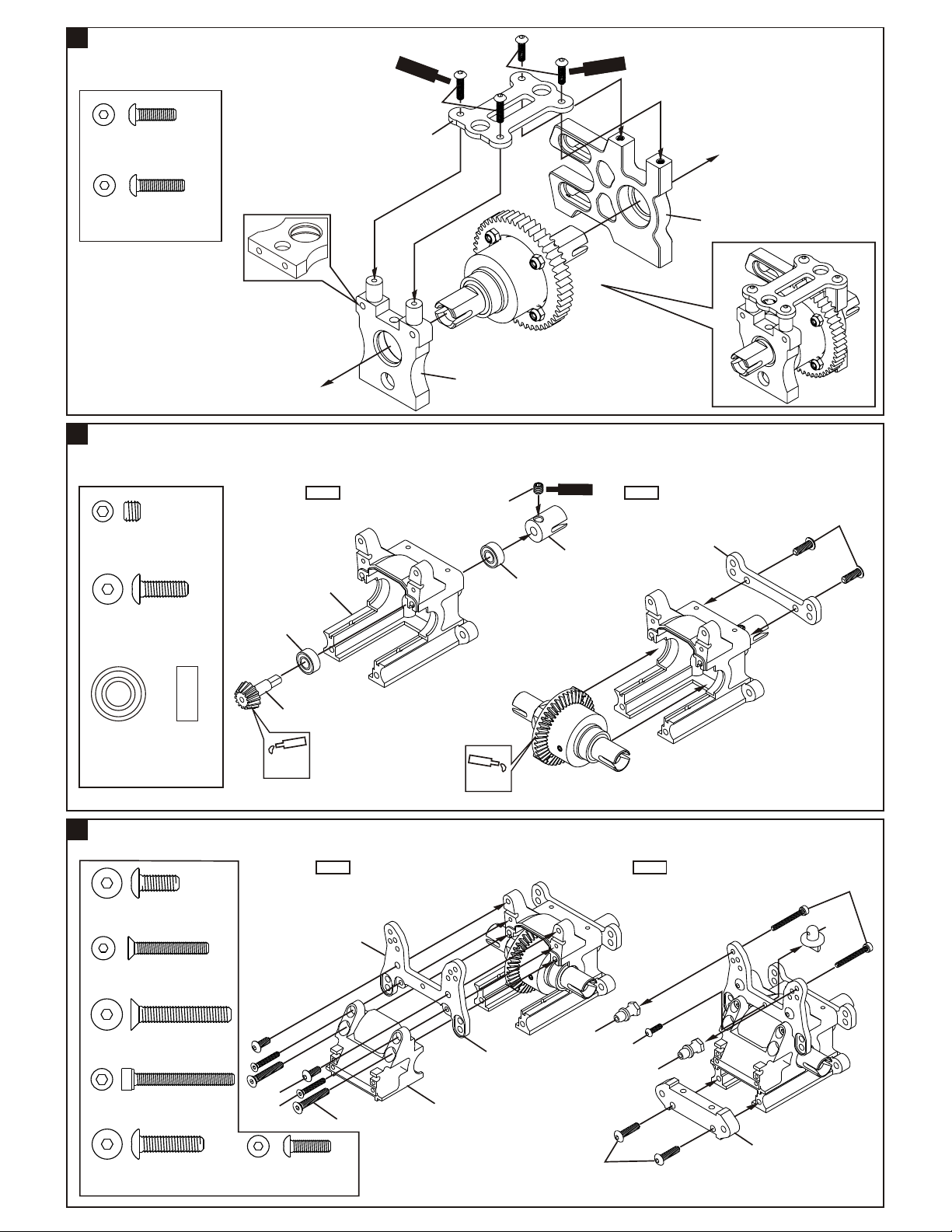
ASSEMBLY OF THE FRONT AND REAR DIFF.
Step 1
94034
4x4mm
Set Screw
30121
3x5mm Screw
94004
3x12mm
Hex Screw
30777
P5 O-Ring
30776
4x10mm Washer
.....x2
.....x8
.....x8
.....x4
.....x8
30779
Step 3
30769
30777
30751
30620
30773
30769
30901
30780
30776
Oil
30769
4x4mm
*Notice the straight
holes are for the
front and rear only.
Step 2
Build two differentials for front and rear.
30751
30777
Step 4
*Apply diff. gear grease
to the differential, during
assembly.
*Fill the diff. case to
approx 80% with grease.
30901
30620
Oil
30780
Tighten
3x12mm
30780
2x12.8mm Pin
30773
4mm Cross Pin
30121
3mm Tube
2
ASSEMBLY OF THE CENTER DIFF.
94034
4x4mm
Set Screw
94020
3x12mm
Flat Head Hex Screw
94004
3x12mm
Hex Screw
.....x4
.....x4
.....x8
.....x1
30779
.....x4
.....x4
Step 5
*Push 3mm tubes into the
30121
holes of the diff. case.
30121
30911
30620
Step 1 Step 2
30769
Step 3
30777
30761
30773
30780
30769
4x4mm
30776
Oil
30769
*Notice the tapered
holes are for the
center diff. only.
30120
30777
*Tighten the diff. screws
in this order.
1
3
30761
30620
Step 4
4
2
30911
Oil
30780
Tighten
3x12mm
30777
P5 O-Ring
30776
4x10mm Washer
30780
2x12.8mm Pin
30773
4mm Cross Pin
.....x2
.....x4
.....x2
.....x2
NB. It is very important to remove
the 30776 washer if the gear
mesh is too tight.
Step 5
3x12mm
*Apply diff. gear grease
to the differential, during
assembly.
*Use Diff. Oil #3000.
3mm
30110
*Tighten the diff. screws
in this order.
1
3
4
2
1
3
ASSEMBLY OF THE CENTER DIFF. MOTOR MOUNT
Sc
re
w
Ce
enm
t
3x12mm
3x10mm
S e
w
r
c
t
n
e
m
eC
94003
3x10mm
Hex Screw
94004
3x12mm
Hex Screw
4
ASSEMBLY OF THE FRONT GEAR CASE
.....x2
.....x2
*Note: the holes for
front diff. mount are
width.
Step 1 Step 2
94036
5x4mm
Set Screw
.....x1
30010
30653
30201
5x4mm
30630
c
S re
30080
30675
w
t
eCem n
4x12mm
30673
94010
4x12mm
Hex Screw
.....x2
30630
30130
30630
6x13x5mm
Ball Bearing
5
ASSEMBLY OF THE FRONT GEAR CASE
.....x2
Apply
Grease
Step 1 Step 2
94009
4x10mm
Hex Screw
94022
3x18mm
Flat Head Hex Screw
94029
4x25mm
Flat Head Hex Screw
90018
3x25mm
Cap Screw
94011
4x16mm
Hex Screw
.....x2
.....x2
.....x2
.....x2
.....x2
4x10mm
3x18mm
94003
3x10mm
Hex Screw
30655
4x25mm
.....x1
30010
Apply
Grease
*Notice the direction.
2
40531
4x16mm
3x25mm
30102
3x10mm
40531
30160
6
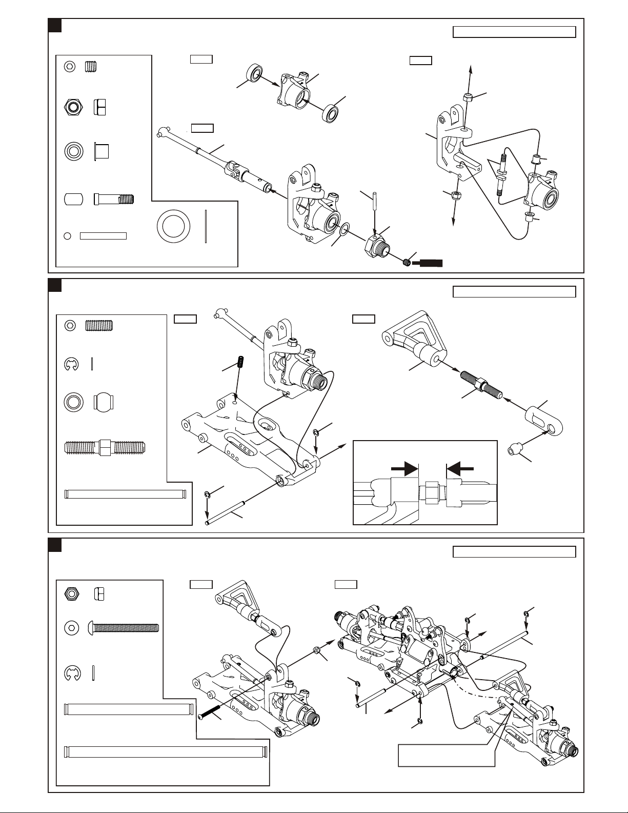
ASSEMBLY OF THE KNUCKLE ARMS
Assemble both right and left side.
Step 1
94034
4x4mm
Set Screw
94042
4mm
Nylon Nut
40527
Knuckle Arm
Bushing
40528
King Pin Screw
36055
2.5x16.8mm Pin
7
ASSEMBLY OF THE FRONT SUSPENSION ARMS
36870
4x10mm
Set Screw
.....x2
.....x4
.....x4
.....x4
.....x2
.....x2
36053
Step 3
34053
40218
8x12x0.3mm Washer
Step 1 Step 2
.....x2
40520
8x12x0.3mm
36053
36055
30656
Step 2
40536
4x4mm
4mm
Nylon Nut
w
cre
S
n
e
m t
Ce
4mm
Nylon Nut
40528
Assemble both right and left side.
40527
40527
90020
2.5mm E-Ring
36850
7mm Ball
36850
5x35mm
Turnbuckle
36170
3x44.3mm Arm Shaft
8
ASSEMBLY OF THE FRONT SUSPENSION ARMS
94041
3mm Nylon Nut
94008
3x25mm
Hex Screw
90021
3mm E-Ring
.....x4
.....x2
.....x2
.....x2
.....x2
.....x2
.....x8
4x10mm
36011
2.5mm
36170
Step 1 Step 2
3mm
2.5mm
3mm
36020
11¡G
*Approx. 9.5mm
36861
36850
Assemble both right and left side.
3mm
3mm
36171
36690
36640
4x47mm Arm Shaft
36171
4x74.1mm Arm Shaft
.....x2
.....x2
3x25
36640
3mm
*Insert the front drive shaft into
cap joint before assembly.
3
9
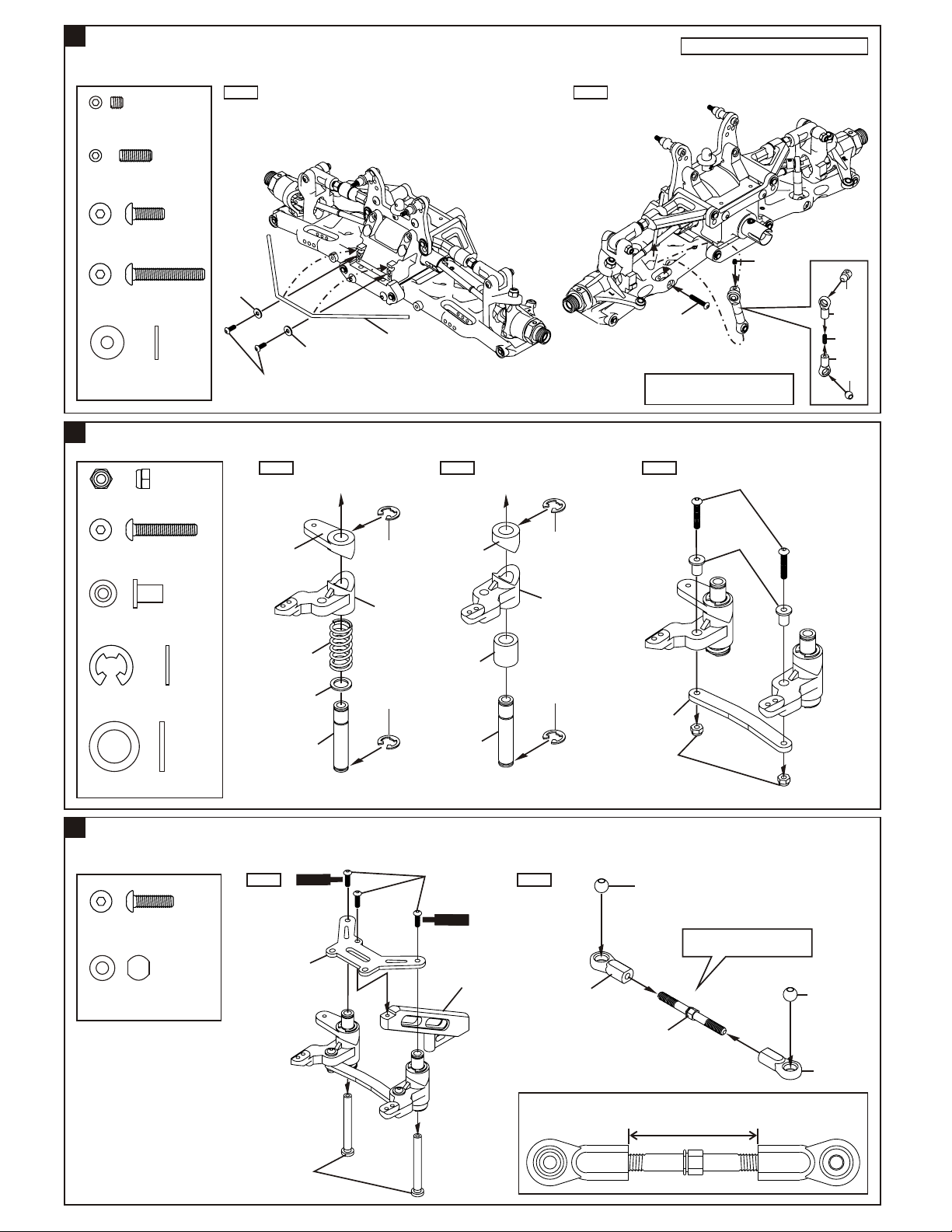
ASSEMBLY OF THE FRONT STABILIZER
Step 1 Step 2
94033
3x3mm
Set Screw
94035
3x8mm
Set Screw
94002
3x8mm
Hex Screw
.....x2
.....x2
.....x2
Assemble both right and left side.
3x3mm
94006
3x18mm
Hex Screw
94040
3x8x0.8mm
Washer
10
ASSEMBLY OF THE SERVO SAVER
94041
3mm Nylon Nut
94005
3x16mm
Hex Screw
36742
Servo Saver Bushing
36743
6mm E-Ring
8x12x1mm Washer
.....x2
.....x2
.....x2
.....x2
.....x2
.....x4
.....x1
3x8mm
Step 1 Step 2 Step 3
8x12x1mm
3x8x0.8mm
30674
36741
30361
34027
36743
30674
36743
30674
30361
30674
36743
30674
36743
3x18mm
*Makes two rods for left and right
hand-side
3x16mm
3x8x0.8mm
36742
30658
3mm
Nylon Nut
30341
40199
3x8mm
40199
30403
11
ASSEMBLY OF THE SERVO SAVER AND STEERING TIE-ROD
w
re
94003
3x10mm
Hex Screw
40038
7mm Ball
.....x3
.....x4
c
30659
30380
S
Ce e
t
m n
Step 1 Step 2
3x10mm
e
r w
c
S
Ce e m n
34014
40038
t
*Made two steering rods
for left and right hand-side.
36700
36790
11¡G
*Approx. 31mm
40038
36700
4
 Loading...