


1:8 SCALE NITRO POWERED TOURING CAR
RTR INSTRUCTION MANUAL
SAFETY PRECAUTIONS
!
This radio control models is not a toy!
- First time builders should seek the advice from people having building experience
in order to assemble the model correctly and to produce it's performance to full
extent.
- Assemble this kit and places out of children's reach!
- Take safety precautions while operating this model. You are responsible
for this models assembly and safe operation!
- Always keep this instruction manual ready at hand for quick reference, even after
completing the assembly.
*SPECIFICATIONS ARE SUBJECT TO CHANGE WITHOUT NOTICE.
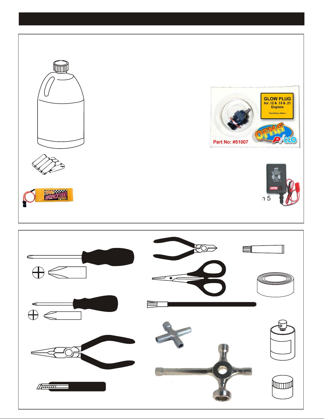
REQUIRED FOR OPERATION
THINGS NEEDED
Glow Fuel
20%
AA Batteries ( 12 pcs )
#10211 NiHm Flat Pack
You will need to buy a few items to start the engine and run the car.
• Use 20% nitro CAR fuel. Do not use airplane or heli fuels, they will
over heat engine.
• Buy long glow plugs, like OFNA/PICCO Plug (#51007). Use plugs
without idle bar. Do NOT buy hot plugs, like the MC-59.
In your box you will find..
• #10163 - Bottle, spout top
• #10218 - Red “C” size glow heater
You need to get batteries for the radio transmitter and the car receiver
packs.
• Radio TX needs (8) eight AA batteries
• Car needs (4) four AA batteries.
Recommendation Option:
You may want to upgrade the car battery pack to a Ni-Cad or NiHm 5
cell type(600AE). This will give more run time. OFNA #10211
1000NiMh Flat Pack and NiHm Battery Charger #10214
TOOLS NOT INCLUDED IN KIT
Phillips Type Screw Drivers ( L )
Phillips Type Screw Drivers ( S )
Needle Nose Pliers
Knife
Instant Cement
Cutter
Curved Scissors
Masking Tape
Brush
Cross Wrench
#17109 $3.95
Paints
Glow Plug & 17MM Cross Wrench
#10801 $6.95
Grease

READ THIS BEFORE RUNNING
Running a nitro kit is fun and easy, but to make this a safe rusting.
and good experience you must observe a few rules. This
kit is extremely fast, easily over 40MPH, and can seriously
injure someone if you are not careful.
Where to run car?
• Any running area you choose must be dry. Do not run
car near any water or wet dirt.
• Do not run on public streets. It is very easy to have the
car run over or damaged by hitting the curb.
• Do not operate car in tight confined places. The car is
very fast and will easily hit something.
• Do not run near people or animals.
and will too easily hit someone.
• Due noise, you will want to consider the surrounding
area when operating the car.
• Do not operate the car at night. You will not be able to
drive it without hitting something.
• Do not operate the car indoors. Engine exhaust is not
healthy.
Glow Fuel
• Glow fuel is poisonous!
• Glow fuel is flammable!
• Do not leave in fuel bottle with lid off at any time. label for additional precautions.
• Don use any fuel other than glow fuel in this engine.
First Time Starting the Engine
Caution! When starting engine make sure the following is
observed. • Always turn off the car BEFORE turning off radio.
• Set engine Master needle to 3 turns (rich setting)
• Do not do this alone, get an experienced friend to help at • DAMAGE DUE CAR RUN AWAY IS NOT A WARRANTY
first. ISSUE.
• Fill fuel tank, try not to spill fuel. Do not spill fuel on
receiver
• Hold car off the ground, so it will not runaway when first
starts
• Turn on Radio and check the linkage before starting
engine.
• Turn on car receiver battery switch.
• Always have an air filter on the carburetor to keep dirt
out.
The car is very fast
• Clear oil and dirt from chassis with a degreaser.
Precautions
• This kit is not a toy. Always run car with a second
person as a spotter and pitman.
• Hot Parts - The pipe, manifold, engine and head are very
hot and will cause burns.
• Rotating Parts - Keep hands away from the drive train,
wheels, and engine when engine is running.
• Radio - Check batteries life before running the car. If
radio does not have full control of the car with steering
and/or throttle/brake do not run until corrected. Failure to
correct this will result in possible injury and damage to the
car or property.
• Glow fuel - Do leave the glow fuel unattended with the lid
off. Fuel contains Methanol and Nitro Methane and is
flammable and poisonous.
Store fuel in cool ventilated location. Refer the glow fuel
• Car Fuel tank - Never store fuel in car tank, it will ruin the
engine if left in tank.
IF YOU DO NOT BREAK-IN ENGINE
CORRECTLY, MAINLY AT LOW RPM,
YOU WILL BREAK THE CONNECTING
ROD!
Engine Break-in
• See Engine Page.
Emergency Stopping Engine When Running
• Remove air filter and cover carb. intake.
• Squeeze fuel line and hold until engine stops.
• With a rag, cover exhaust outlet.
Storing Car After Running
• Remove fuel from tank and fuel lines
• Turn off radio in car
• Put a few drops of after run in engine to keep it from
FAILURE TO NOT READ AND
FOLLOW BREAK-IN ENGINE
INSTRUCTIONS WILL VOID
WARRANTY!
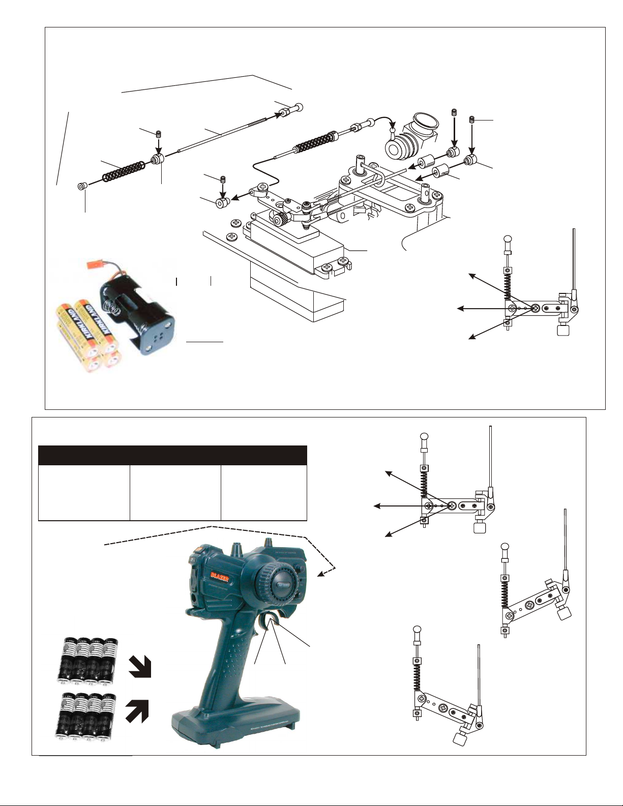
ASSEMBLY OF THE THROTTLE LINKAGE SYSTEM
#30800
Plastic Throttle
kit
Throttle
Spring
Plastic Collar
* Take the plastic collar
from brake system plastic
parts.
3X3mm
Set Screw
#30530
Plastic Throttle
Ball Joint
2mm Rod
3X3mm
Set Screw
#10300
Alum.Stopper
Place battery pack in a plastic bag before
securely tie wrap pack to radio plate. Pack
will fall out if not securely mounted! Check
the battery pack if you have any radio
interference, don’t run car if you see a
problem..
* Snap On.
Brake
Idle Position
Full Throttle
3X3mm
Set Screw
#10300
Fuel
Tube
( 6mm )
Alum.Stopper
* Align throttle servo same
as shown.
CHECKING ENGINE THROTTLE
A
1. Insert AA batteries into
transmitter (8 Pcs).
2.Turn on transmitter.
3.Turn on receiver.
4.Center throttle trims as
shown .
IMPORTANT
CHECK RADIO THROTTLE
AND STEERING SWITCHES
BEFORE RUNNING CAR
* Insert into transmitter.
1. Pull Full Throttle.
B
C
1. Push trigger to full
brake position.
2. Adjust alum. Stopper to
increase or decrease
the brake.
B
A
* Align throttle servo same
as shown.
Brake (C)
A
Idle Position (A)
Full Throttle (B)
• Full throttle arm position.
Spring rod pulls throttle
barrel open and brake
rods release pressure on
brake cams.
C
B
C
• Full brake arm position.
Spring compresses
forward and brake rods
pull brake levers.
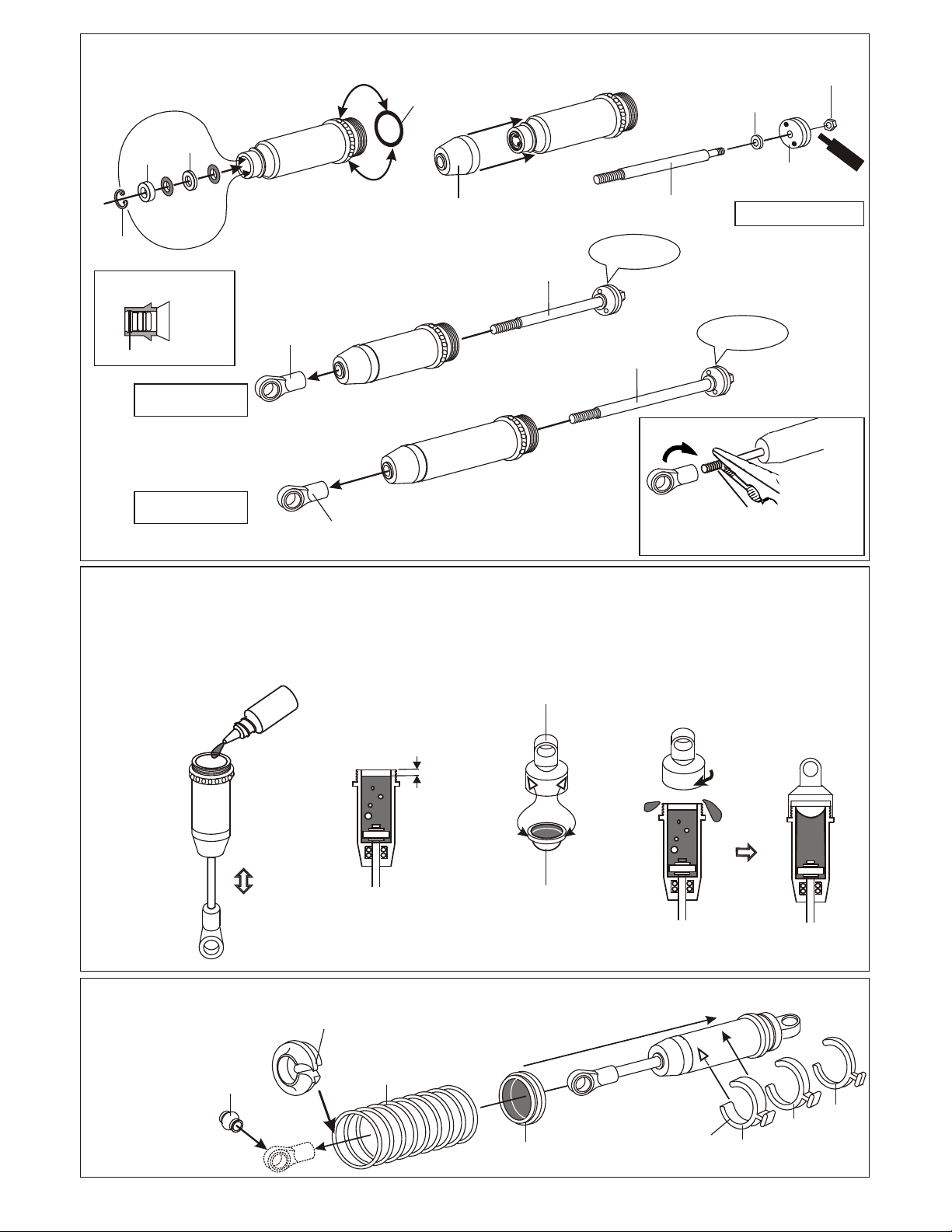
SHOCK ASSEMBLY
1mm
Washer
2mm
Washer
32237
Rebuild
7mm
E-Ring
* Note the E-Ring must
fit into groove as shown.
Kit
* Fit into groove.
Oil Seal
32203
Dust Pusher, Short
(Yellow Rubber)
32205
Dust & Shaft
Protector, long
*Push onto shock
cylinder.
32292
Front. 3.5mm
Short Shaft
Shock Shaft
* Short shaft
for front.
2.6 x 5mm
Washer
* Assembly 4 pieces of the
shock shaft .
30671
Front Shaft, 3.5mm
with Piston
Piston
2.6mm Nut
Scre
Ce
men
w
t
32051
E-Ring
6mm Ball End
( Make 2 for front.)
( Make 2 for rear. )
32051
6mm Ball End
FILLING THE SHOCKS WITH OIL
1. Pull down piston and pour oil into
shock cylinder. Remove air bubbles
by slowly moving piston up and down.
Silicone
Oil
2. Pull down piston, attach pressure top
and shock oil overflow with tissue
paper.
*Leave 3mm.
32043
Cap, blue
32236
Rear, 3.5mm
Long Shaft
3. Tighten up shock cap.
* Long shaft
for rear.
30672
Rear Shaft, 3.5mm
with Piston
* Be careful not to damage shock shaft.
* Screw down cap.
UP
down.
*Move Slowly.
ASSEMBLY OF THE SPRING
Spring Holder
30403
6mm
Ball Joint
* Push 6mm ball joint
into ball end.
32300
Front, Spring Pair, GTP
32301
Rear, Spring Pair, GTP
32033
Pressure Top
Fit into groove.
*
32051
Misc. Plastic Shock Parts
*Slide spring collar into Shock.
Spring Collar
32051
Misc. Plastic Shock Parts
(Standard)
1mm
3mm
5mm
*Spring Tension adjust .er

ASSEMBLY OF NEW “K” STYLE DIFFERENTIAL CASE AND GEARS
31324 - FRONT OR REAR DIFF UNIT
31325 - CENTER DIFF UNIT
30779
2 x 12.8mm
Pin
* Position the O-ring
as shown.
30751 Diff. Case ( Front/Rear )
30761 Diff. Case (Center )
30779
2 x 12.8mm
Pin
30771
Diff. Shaft
30779
P5 O-Ring
( Orange )
30779
0.5 x 26mm
O-Ring
30769
Diff. Bevel Gear
( Large )
30779
4 x 10mm
Washer
* Apply diff. Gear grease to the
differential, during assembly.
* Fill the diff. Case to
approx 70% with grease.
Grease
30769
Diff.
Bevel Gear
( Small )
30773
4mm
Cross Pin
30769
Diff.
Bevel Gear
( Small )
30773
4mm
Cross Pin
30779
4 x 10mm
Washer
30769
Diff.
Bevel Gear
( Small )
30779
4 x 10mm
Washer
NB. It is very important to remove
the 30779 shim if the mesh
is too tight.
30771
Diff. Shaft
30769
Diff.
Bevel Gear
( Large )
ASSEMBLY OF THE BEVEL GEAR
( Builds two differentials for front and rear. )
30120
Bevel Gear
(Large/Metal)
31010
Optional - Bevel Gear
(Harden Steel)
30121
3mm
Tube
30779
P5 O-Ring
( Orange )
30121
3 x 5mm
Screw
30751 Diff. Case ( Front/Rear )
30761 Diff. Case (Center )
Sc
rew
Ce
me
nt
36730
Cap Joint
90026
5 x 5mm
Set Screw
30620
7 x 19mm
Bal lbearings
90026
5 x 5mm
Set Screw
3x10mm
Tapping Screw
3x10mm
Tapping Screw
Scre
Cem
w
t
en
* Push 3mm tubes into
holes of the diff. Case.
* Notice the straight holes
are for front and rear.
30121
3mm
Tube
30121
3 x 5mm
Screw
(Small Head)
5 x 5mm
Set Screw
3 x 5mm
Screw
30620
7 x 19mm
Ball bearings
36730
Cap Joint
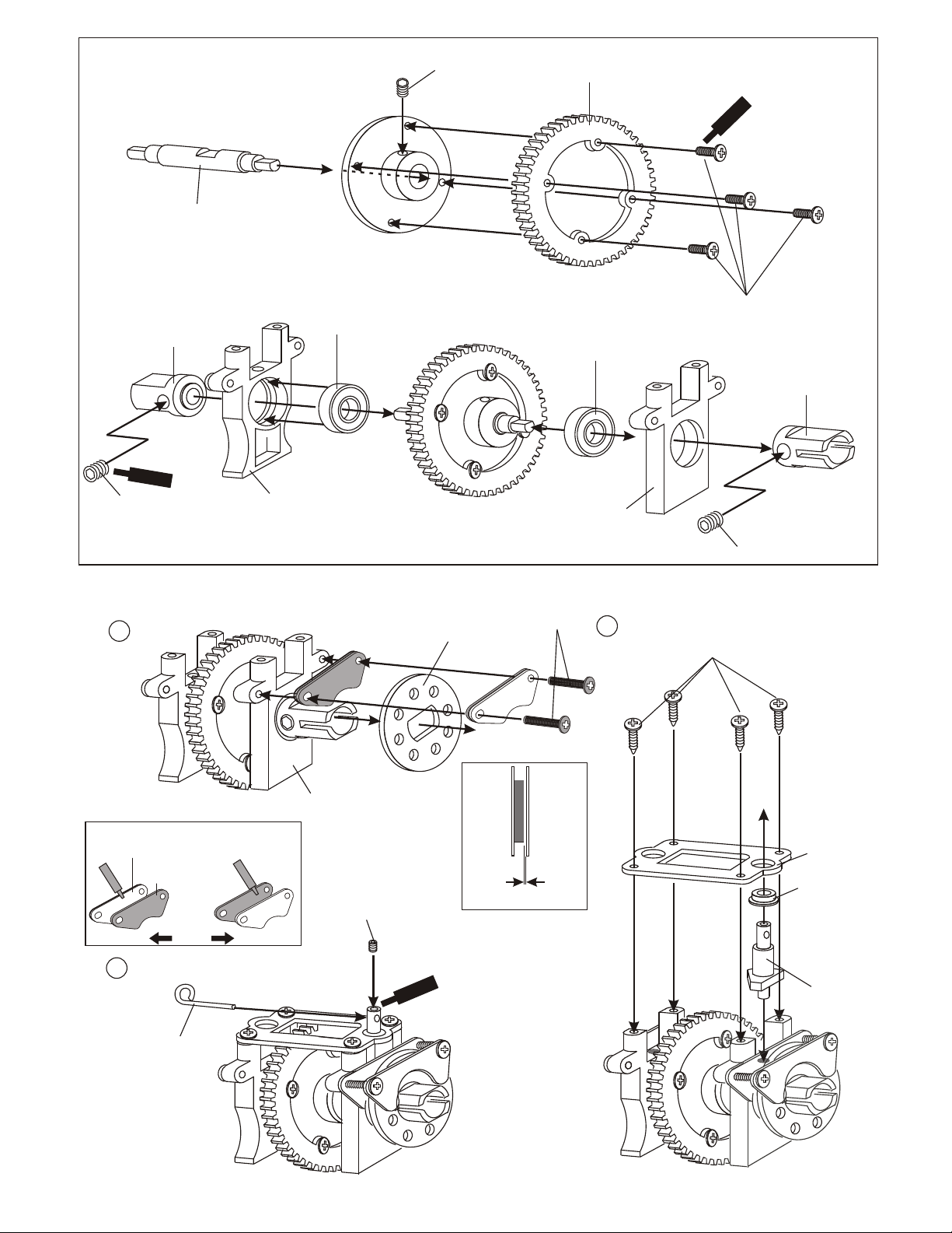
ASSEMBLY OF THE SPUR GEAR
(Solid Center Drive)
33020
Center Gear
Shaft
30170
Brake Joint, Drive Cup
Screw
Cement
30201
90026
5 X 5mm
Set Screw
Center
Diff. Mount
33020
Center Gear
Mount
7 x 19x 5mm
Ball Bearings
90026
5 X 5mm
Set Screw
30110
Spur Gear
7 x 19x 5mm
Ball Bearings
30201
Center
Diff. Mount
ew
Scr
ement
C
3 x 10mm
Screw
90026
5 X 5mm
Set Screw
30170
Brake Joint, Drive Cup
ASSEMBLY OF THE CENTER PLATE
1
30201
* Apply instant cement to
glue brake pad and packing.
(Rear)
36660
Brake Pad
36661
Brake Pad
Packing
(Front)
Center
Diff. Mount
(Front)
3
3 x 3mm
Set Screw
Scr
Cem
ew
ent
36650
Brake Disc
(Steel)
Leave 0.5mm
3x12mm
Screw
2
3 x 10mm
Tapping Screw
30652
Center Plate
30211
Plastic
Bearing
or
30212
Flange Ball
Bearing, option
30213
Brake Cam
30171
Brake Lever
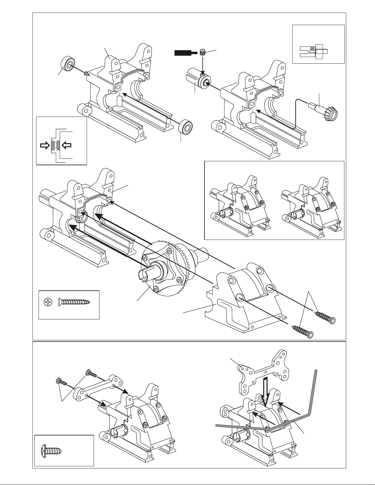
ASSEMBLY OF THE GEAR BOX
( Assemble two gear boxes for front and rear. )
30010
1
30630
6 x 13 x 5mm
Ball Bearing
* Insert two ball bearings
as shown.
3
Gear Box
30010
Gear Box
Screw
Cement
36730
Cap Joint
30630
6 x 13 x 5mm
Ball Bearing
2
5 x 5mm
Set Screw
* Make two gear boxes for front and
rear.
* Place set screw in D cut.
30130
Bevel Gear
4 x 20mm Flat Head
Tapping Screw
Front Diff. Assembly
ASSEMBLY OF THE FRONT SHOCK TOWER
4 x 10mm
Tapping Screw
4 x 10mm
Tapping Screw
30010
Gear Box
Cover
34008
Front Shock Tower,GTP
4 x 20mm
Flat Head
Tapping Screw
* Insert the stabilizer before
assembly th shock stay.
30340
Stabilizer Bar
ASSEMBLY OF THE FRONT ARM HOLDER
3 x 20mm
Flat Head
Tapping Screw
1
0
4 x 15mm
Tapping Screw
( Small Head )
1
0
4x10mm
Tapping Screw
4 x 15mm
Tapping Screw
( Small Head )
30160
Front Lower
Arm Holder
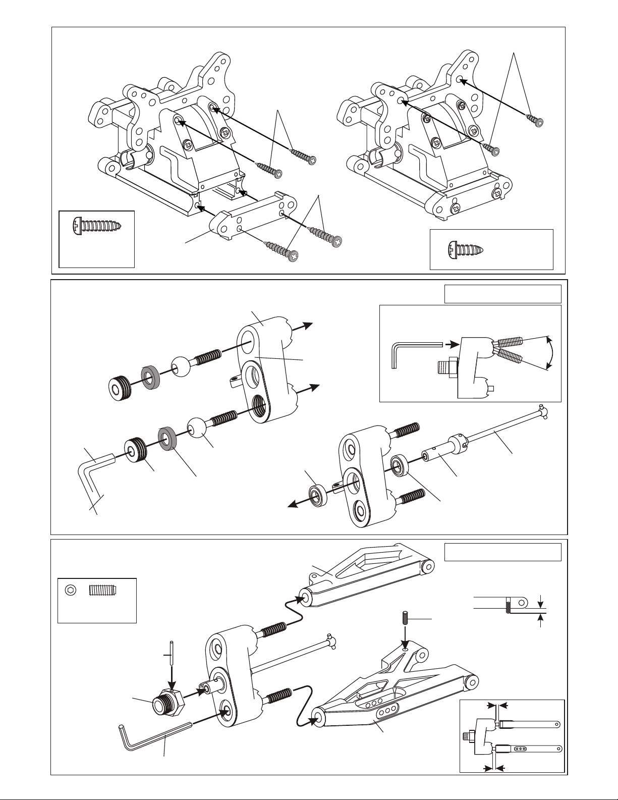
ASSEMBLY OF THE FRONT
PIVOT BALL KNUCKLE ARM
* Use 5mm
hex wrench.
36904
14mm
Alum. Nut
36903
13.8mm
Steering Ball
36905
Steering Ball
Washer
36901
Ball Type
Knuckle Arm
( Right and Left )
R
* Note the "R" mark
is for righthand side.
36053
8x16mm
Ball Bearing
4 x 10mm
Tapping Screw
( Small Head )
Assembly of the right and left hand side
are the same.
* Adjust alum. Nut to
keep steering ball
smoot.
R
8mm
Axle
36053
8x16mm
Ball Bearing
36052
CVA
Constant Velocity Axle
ASSEMBLY OF THE FRONT KNUCKLE ARM
INTO FRONT ARM
4 x 10 mm
Set Screw
36055
2.5 x 17mm
36054
Wheel Hub
( Alum. )
Pin
* Use 2.5mm
Hex Wrench.
R
36900
Front
Upper Arm
36890
Front
Lower Arm
Assembly of the right and left hand side
are the same.
* A 4 x 10mm set screw is used
to adjust the ride height.
36870
4x4mm
Set Screw
3mm
3.5mm
* Approx 3mm.
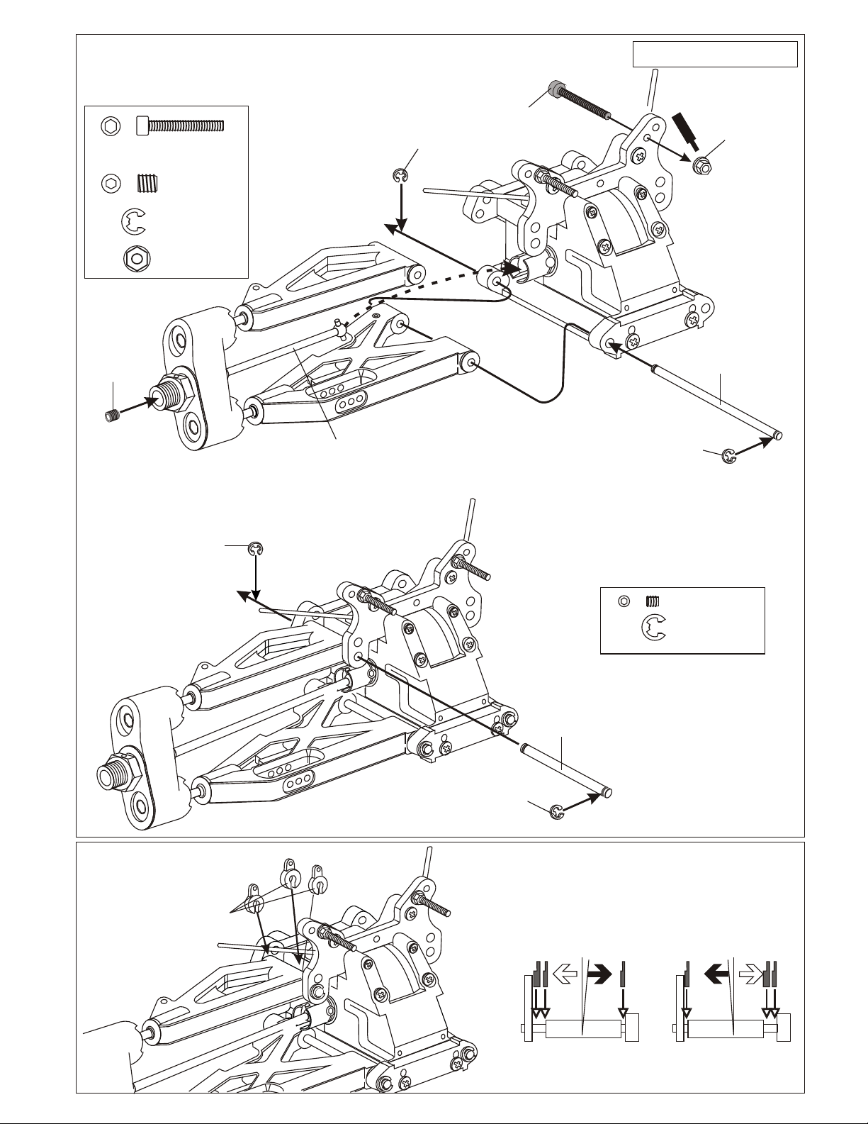
ASSEMBLY OF THE FRONT ARM ONTO GEAR BOX
3 x 20mm
Cap Screw
5 x 5mm
Set Screw
3 mm E-Ring
M3 Flange Nut
( Steel )
5x5mm
Set Screw
* Do not over tighten
5x5mm set screw.
RR
* Insert drive shaft
before assembly.
3mm
E-Ring
3x25mm
Cap Screw
Assembly of the right and left hand side
are the same.
S
3mm
C
cre
e
m
Flange Nut
w
ent
1
0
30151
Lower Arm Shaft
3mm
E-Ring
90021
3mm
E-Ring
RR
ASSEMBLY OF THE CASTER ADJUSTER
36905
Caster Angle
Adjuster
3 x 3mm Set Screw
3 mm E-Ring
30152
3mm
E-Ring
Upper arm Shaft
Caster angle will
become bigger.
* o change
use adjuster t
the caster angle .
Caster angle will
become less.
1
0
1
0
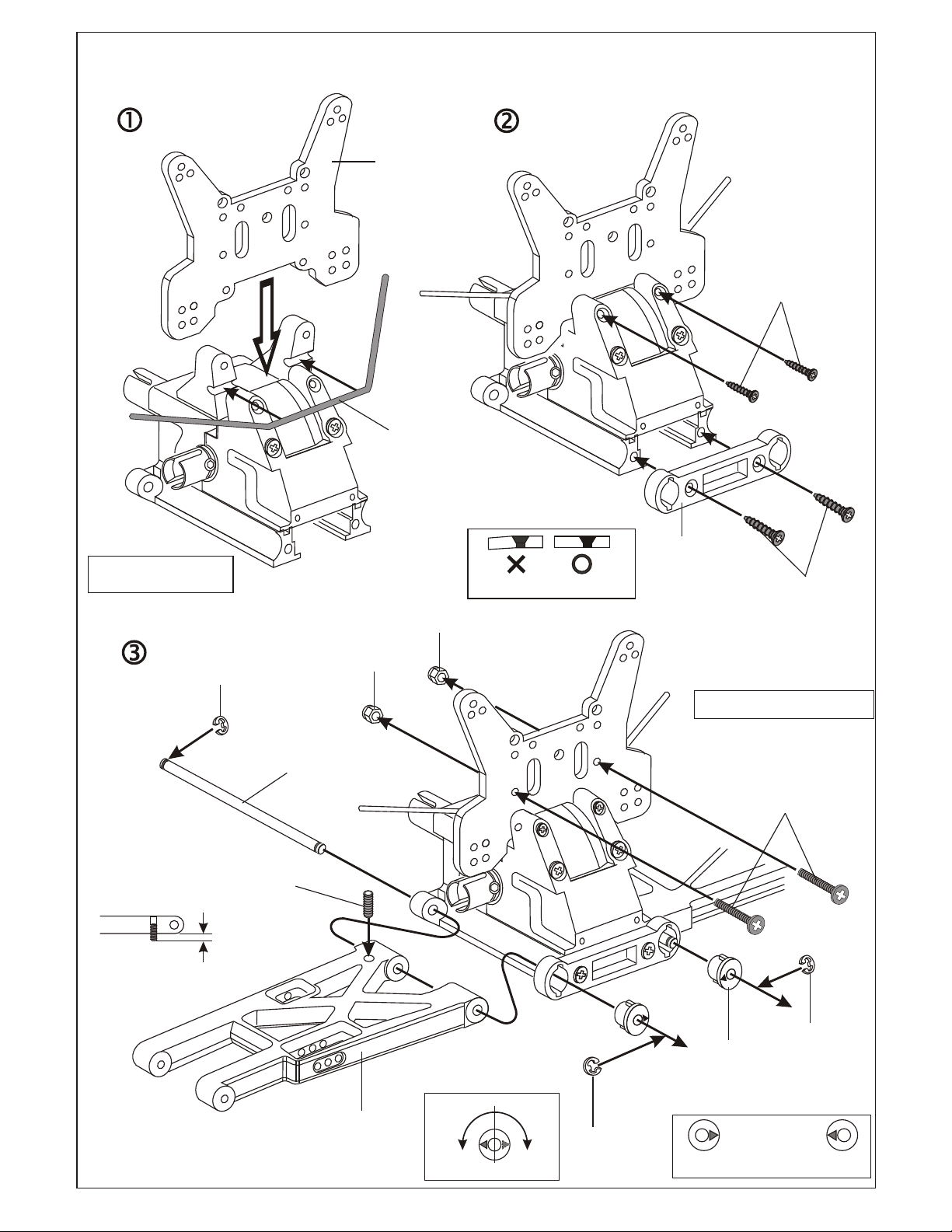
ASSEMBLY OF THE REAR SHOCK TOWER
34009
Rear Shock
Tower, GTP & WII
30340
Stabilizer Bar
3 x 20mm
Flat Head
Screw
* Insert stabilizer before
assembly of the shock tower
3mm
E-Ring
* A 4 x 10mm set screw is used
to adjust the ride height.
* Approx 3mm.
30151
Arm Shaft
(Long)
4 X 10mm
Set Screw
M3
Nylon
Lock Nut
M3
Nylon
Lock Nut
* Don't over tighten tapping screw.
30351
Rear Lower Arm
Holder
Assembly of the right and left hand side
are the same.
3 x 15mm
Screw
4x16mm
Flat Head
Tapping Screw
36030
Rear Lower
Arms
1
Degree
Fig.1
1.5
Degree
3mm
E-Ring
30350
Rear Wheel
Toe-in Cams
* Set triangle marks in
the direction shown
in Fig.1.
3mm
E-Ring
ASSEMBLY OF THE REAR HUB
36081
Rear Hub
* Builds two upper Rods for left and right side.
36880
5x60mm
Turnbuckle
36053
8 x 16 x 5
Ball Bearings
36053
8 x 16 x 5
Ball Bearings
36055
2.5 x 17mm
Pin
36054
Wheel Hub
( Alum. )
Assembly of the right and left hand side
are the same.
ASSEMBLY OF THE REAR DRIVE SHAFT
36082
Rear Wheel
Axle Shaft
36690
7mm Plastic
Arm Ball End
36850
7mm Ball
36690
7mm Plastic
Arm Ball End
* Anticlockwise mark.
42mm
0 10 20 30 40 50
Assembly of the right and left hand side
are the same.
mm
90020
2.5mm
E-Ring
5x5mm
Set Screw
* Do not r tighten
5x5mm set screw over tighten.
* Insert rear drive shaft
befor assembly.
36110
Rear Drive
Shaft
36170
3mm
Rear Arm Shaft
90020
2.5mm
E-Ring
ASSEMBLY OF THE REAR UPPER ARM ROD
M3
3 x 20mm
Cap Screw
3 X 25mm Cap Screw
3mm
Nylon Lock Nut
3mm
Nylon Lock
Nut
* Insert into rear hub.
Nylon
Lock Nut
3 x 20mm
Cap Screw
Assembly of the right and left hand side
are the same.
t
t
en
en
ew
ew
cr
cr
S
S
Cem
Cem
3mm
Flange Nut
ASSEMBLY OF THE REAR STABILIZER ROD
30401
6mm
Stabilizer
Ball End
30402
3 X 30mm
30401
6mm
Stabilizer
Ball End
30403
6mm
Ball Joint
Tie Rod
3 x 3mm
Set Screw
3 x 15mm
Screw
3 x 25mm
Cap Screw
15mm
0 10 20 30 40 50
mm
w
re
Sc
Cement
30340
6mm
Stabilizer
Ball End
* Insert the stabilizer rod into arms
before assembly.
3 x 15mm
Screw
3 x 15mm Screw
ASSEMBLY OF THE SERVO SAVER
(36740 Servo Saver Plastic parts)
36743
6mm
E-Ring
36740
Servo Saver
Horn B
36741
Servo Saver
Spring
36740
Servo Saver
Horn A
36743
6mm
E-Ring
36740
Servo Saver
Top Adapter
36740
Servo Saver
Horn B
3 x 15mm
Screw
36742
Servo Saver
Bushing
36742
Servo Saver
Bushing
36740
Servo Saver
Shaft
(Brass)
36743
6mm
E-Ring
Plastic Tube
36743
6mm
E-Ring
36741
8x12mm
Washer
36740
Servo Saver
Shaft
(Brass)
ASSEMBLY OF THE FRONT PLATE AND
STEERING ROD
3 X 10mm
Screw
30540
Front Plate
30410
6mm
Ball & Socket
3mm
Nylon Lock Nut
M3 Nylon Locknut
3 x 15mm Screw
6 mm E-Ring
3mm
Nylon Lock Nut
36750
Servo Saver
Connector
* Made two steering rods for left and right-side.
30410
6mm Steering
30400
3 x 46mm
Turnbuckle
30410
6mm Steering
Ball End
Ball End
30410
6mm
Ball & Socket
30380
Servo Saver
Post
* Anticlockwise mark.
( Left-Side )
35mm
( Right-Side)
35mm
0 10 20 30 40 50
mm

ASSEMBLY OF THE FRONT PLATE AND
STEERING ROD
3x15 Flat Head
Screw
Front Steering Rod
( Right )
ASSEMBLY OF THE FRONT PLATE
ONTO THE FRONT GEAR BOX
3 x 20mm
Flat Head Screw
3x10mm
Tapping Screw
¦Û§ð¤úÁ³µ·
Front Steering Rod
( Left )
3 x 15mm Flat Head
Screw
3 x 20mm
Flat Head Screw
Knuckle Arm
( Left-Side )
3mm
Nylon Lock Nut
R
3mm
Nylon Lock Nut
ASSEMBLY OF THE STABILIZER ROD
(#30340 Anti-roll Kit)
30402
3 X 30mm
30401
6mm
Stabilizer
Ball End
30403
6mm
Ball Joint
Tie Rod
30411
6mm
Ball Joint
3 x 15mm
Screw
RR
3 x 3mm
Set Screw
30340
6mm
Stabilizer
Ball End
3 x 10mm
1
0
1
Tapping Screw
3 x 20mm Flat Head
Screw
3mm nylon
Lock Nut
0
15mm
0 10 20 30 40 50
mm
* Insert stabilizer rod
into upper arm.
30mm
Assembly of the right and left hand side
are the same.

ASSEMBLY OF THE FRONT GEAR BOX ONTO
CHASSIS
R
34040
Chassis
* A 3 x 10mm flat head screw
are for servo post.
3 x 25mm
3 x 25mm
Flat Head
Flat Head
Tapping Screw
Tapping Screw
11
00
3 x 25mm Flat Head
Tapping Screw
3 x 10 mm
Flat Head
Screw
ASSEMBLY OF THE FRONT BUMPER
3 x 10mm
Flat Head
Screw
1
R
0
4 x 20mm Flat Head
Tapping Screw
4 x 20mm
Flat Head
Tapping Screw
4 x 20mm
Flat Head
Tapping Screw
34090
Front Bumper, GTP

ASSEMBLY OF THE CENTER DRIVE SHAFT
Center Gear Assembly
34040
Chassis
4 x 16mm
Flat Head
Tapping Screw
R
34050
Center Drive
Shaft (Front)
* Insert drive shaft into
cap joint.
1
0
4 x 16mm
Flat Head
Tapping Screw x4
4 x 16mm
Flat Head
Tapping Screw
34050
Center Drive
Shaft (Rear)
* Insert drive shaft into cap joint.
3 x 25mm
Flat Head
Tapping Screw x2
4 x 16mm
Flat Head
Tapping Screw x4
3 x 25mm
Flat Head
Tapping Screw
( 2 Pcs )
4 x 16mm
Flat Head
Tapping Screw

ASSEMBLY OF THE STONE GUARD
34080
Nylon
Stone Guard
(Right-Side)
3 x 10mm
Flat Head
Tapping Screw
3 x 10mm
Flat Head Screw
( 3 Pcs)
34080
Nylon
Stone Guard
(Left-Side)
1
0

3 x 5mm Screw
3 X 8mm
Washer
3 x 20mm
Cap Screw
3mm Nylon
Locknut
#10398 - 12T
#10399 - 13T
#10400 - 14T (stock)
#10401 - 15T
#10402 - 16T
#10403 - 17T
#10404 - 18T
Clutch Bells
#34110
5x10x4mm
Ball Bearing
Notes:
Non-Pull Start Engines...
• Alum. Washer behind the flywheel is not needed when using Force engines or similar types. O.S. Engines will
require washer spacer.
• To check!..place the brass corn against the engine bearing, then flywheel. You should be covering one or two
thread of the engine shaft. If this is the case, you do not need an additional washer behind the flywheel.
You must cut the engine shaft if too long. Count 6 threads in front of the flywheel and mark. This is all you need to
tighten the clutch nut and mount the flywheel.
Force Pull Start Engine...
• Force Pull Start Engines required NO spacer and no shaft cutting. The engines comes with an alum cast driver
washer, you use this part as the spacer, not the alum. washer shown. Also, use the special flywheel brass corn.
This corn fits the thread shaft diameter so you can tighten the flywheel against the drive hub.
#10010
#10100
Clutch Spring
#34110
5x10x4mm
Ball Bearing
Clutch Shoes
Black Type
ASSEMBLY OF THE CLUTCH INTO ENGINE
#10329
Brass, Corn
(sml hole)
SEE NOTES ABOVE
3 x 20mm
Hex Screw
3 x 20mm
Hex Screw
3mm
Nylon Lock
Nut
3 x 8mm
Washer
3 x 5mm
Screw
Misc. Hardware
#10099
* Fit the flywheel using a cross
wrench or deep socket.
If engine turns when tightening,
hold piston with large thick tie-wraps
and hard wood in exhaust port.
Do not use metal, it will
damage engine.
* Place the clutch shoes
with the clutch springs
over the 3 pins of the
flywheel.
Using a screw driver as a lever,
bend the small end of the
clutch spring behind the
clutch nut and press
down to snap shoe in
place.
ASSEMBLY OF THE AIR FILTER
You must oil foam filter before use.
Filter will not work if not oiled.
Clean with soap and water only.
You will damage foam if washed
if fuel!
#10016
Air Filter
Sponge
Refills
#10091
Clutch Nut
screw type
* Shoes are
trailing.
Nylon Strap
( Small )
#10040 (stock)
3 Pin
Flywheel, Taper
#10041
3 Pin
Flywheel, Hole
#10021 - Black
#10027 - Yellow
#10028 - Pink
#10029 - Blue
Air Filter Connector
#30480
Engine Mount
#10098
SG Nut & Shim KiT
Engines with ground shafts and few threads
are called SG Shaft. A special clutch nut is needed.
The stock flywheel (#10040) is fine.
Nylon Strap
( Small )
3mm
Nylon Lock
Nut
3 x 10mm
Tapping Screw
#10017 - Blue
#10018 - Yellow
#10019 - Rose
Foam Air filters Unit

INSTALLATION OF THE FUEL TANK
AND ENGINE ONTO CHASSIS
3 x 15mm
Screw
30289
Pressure Nipple
Note Book Paper
3 x 15mm
Screw
30288
Plastic Post
30280
Fuel Tank
30288
Plastic Post
30289
Fuel Nipple
3 X 20mm
Cap Screw
*Use note book paper to set
gear backlash between spur gear
and clutch bell gear.
If the space is not correct the spur gear
will be damaged.
Spur Gear
90 degree
* Loose or tighten 3x20mm cap screw
and 5x10mm hex screw to align
spur gear and clutch bell gear to 90
degree.
Clutch Bell
3 x 10mm
Tapping Screw
ASSEMBLY OF THE MANIFOLD AND
MUFFLER
* Read this page with very carefully.
4mm
Nylon
Lock Nut
30491
Muffler Wire
4x1omm
Flat Head
Screw
5x5mm
Set Screw
3 x 10mm
Tapping Screw
30490
Muffler
10068
Manifold Adapter
( Red Silicone )
10079
Pressure Nipple
* Drill a hole (Size 3.5mm)
in the place and align as shown.
Use a two part epoxy glue to
full seal the nipple base to the
nipple.
10111
5x12mm
Washer
( 4 pcs )
5x10mm
Hex Screw
( 4 pcs )
10060
Manifold
10180
Silicone Tube
10120
Manifold
Spring
*Tighten the strap
and cut off the excess.
Nylon Strap
( middle )

ASSEMBLY OF THE FUEL TUBE
* Connect to fuel tank
pressure nipple.
ASSEMBLY OF THE RADIO TRAY AND SERVO
3 x 10mm
Tapping Screw
3 x 10mm
Tapping Screw
34061
Radio Tray
3 x 10mm
Tapping Screw
* Connect to
carburetor.
* Connect to
* Connect to
press nipple.
* Use the screw provided
with your witch.
fuel nipple.
Fuel Tube
34032
Cover of the
receiver box
3 x 10mm
Tapping Screw
34032
Receiver Box
3 x 10mm
Tapping Screw
Throttle Servo
34020
Servo Mount
34031
Radio Tray
Pos, Nylont
30520
Radio Tray
Post, Alum.
3 x 10mm
Tapping Screw
Steering Servo
10280
Switch
Cover
* Connect switch wire
to receiver.
Switch
Receiver
Battery Case
* Connect the wire to
receiver.
* Connect battery case
wire to switch.
34020Servo Mount

ASSEMBLY OF THE REAR STIFFENER
3 x 10mm
34070
Rear
Stiffener
2.6x10
Tapping Screw
Screw
2.6x10
Tapping Screw
ASSEMBLY OF THE BRAKE SYSTEM
( Use #30800 brake linkage plastic parts set. )
3X3mm
Set Screw
36140
2mm
Adjust Nut
Servo Mount
Adjust
Mount
2x25mm
Screw
ASSEMBLY OF THE SERVO HORN LINKAGE
INTO SERVO
3x12mm
Screw
Screw
Cemen
3mm
Nut
Slider
t
* Use the screw provided
with your radio.
2x8mm
Screw
Servo Horn
2mm Nut
30172
2mm Rod
* Use the small strap to
secure the servo wire.
2x4mm
Screw
2x6mm
Washer
2x4mm
Screw
2x6mm
Washer
2mm
Tie-Rod End
2mm
Tie-Rod End
* Use the screw provided
with your radio.
Steering
Servo Horn

ASSEMBLY OF THE STONE GUARD
34080
Nylon
Stone Guard
(Right-Side)
3 x 10mm
Flat Head Screw
( 3 Pcs)
34080
Nylon
Stone Guard
(Left-Side)
Assembly of the right and left hand side
are the same.
Antenna Post
30560
Antenna Tube

ASSEMBLY OF THE THROTTLE LINKAGE SYSTEM
(Part of 30800 linkage kit)
3X3mm
Set Screw
Throttle
Spring
30172
2mm Rod
30530
Throttle
Ball Joint
3X3mm
Set Screw
* Snap On.
3X3mm
Set Screw
10300
Alum.Stopper
Plastic Collar
* Take the plastic collar
from brake system plastic
parts.
10300
Alum.Stopper
ALIGN THROTTLE SERVO AND BRAKE SAME AS SHOWN
( Neutral Position )
Engine at idle
* Align throttle servo same
as shown.
Brake
Idle
Position
Full Throttle
Less Brake
More Brake
Loose
* Tighten or loose the adjuster nut
will change the brake.
Tighten
( Braking Position )
Brake is not on
Brake is on
Brake Adjust Nut
( Full Throttle Position )
Engine at full throttle
Brake is not on

ASSEMBLY OF THE FRONT STEERING ROD
30410
30411
6mm
Ball & Socket
30402
3 X 30mm
Tie Rod
6mm Ball End
30411
6mm
Ball & Socket
0 10 20 30 40 50
20mm
mm
30410
6mm Ball End
3x12mm
Screw
3x12mm
Screw
* Align the steering servo as shown.
3x10mm
Tapping
Screw
30660
Front Stiffener
3 X 10mm
Screw

ASSEMBLY OF THE FRONT AND REAR SHOCKS
ONTO THE SHOCK TOWER
R
1
0
3 x 15mm
Screw
Assembly of the right and left hand side
are the same.
Plastic Washer
or
Use CNC Alum Spacer, 4 purchase.
#36507 $4.95
30403
6mm
Ball Joint
3 x 8mm
Washer
3mm
Nylon
Lock Nut
Screw
Ceme
nt
3 x 15mm Screw
3mm Nylon Locknut
3 X 8mm Washer
* Insert shock ball end
into arm.
Plastic Washer
37380
6mm
Ball Joint
Assembly of the right and left hand side
are the same.
6mm ²yÀY
3 x 8mm
Washer
3mm
Nylon
Lock Nut
Screw
Ceme
nt
3 x 15mm
Screw
* Insert shock ball end
into arm.

ASSEMBLY OF THE FRONT BODY POST
33011
Body Post Set
R
33011
Front
Body Post
1
0
ASSEMBLY OF THE FRONT FOAM BUMPER
33011
Foam Bumper
Cover
1
R
0
34091
Foam Bumper
R
4x15mm
Tapping Screw
(Small Head)
33011
Body Supporter
31149
Clips
31149
Clips

ASSEMBLY OF THE REAR BODY MOUNT
3mm
Nylon Nut
33010
Body Mount
3 x 15mm
Screw
3 x 15mm
Screw
Rear
Body Post
2mmNut
2x18mm
Screw
ASSEMBLY OF THE REAR BODY SUPPORT
* Use this body post
for rear.
31149
Clips
33011
Body Supporter
31149
Clips

ASSEMBLY OF THE TIRES AND WHEELS
#86044 - Red
86059
Inner Sponge
(Small)
* Take off
double side tape.
86049
Chrome Wheel
#86045 - White
#86046 - Lime
#86047 - Yellow
#86048 - Black
#86049 - Chrome
17mm 5-Star Wheels,
Two (2) Pairs per bag.
86059
Inner Sponge
(Large)
* Use foam cement
to glue together.
Not CA Glue.
* The tires might be different
as picture shown.
86050
Slick Tires
*Put the tire into
the groove of the
wheel.
* Put the sponge on the middle
of the wheel.
#86050 - Slick Tire, No-belt
#86051 - Slick Tire, Belted
#86052 - Treaded Tire, No-belt
#86053 - Treaded Tire, Belted
#86504 - Pre-glued Set, Slick/White
#86505 - Pre-glued Set, Tread/White
#86508 - Pre-glued Set, Slick/Chrome
Using 17mm 5-Star Spoke Wheels, pairs
* Apply instant glue into
* Apply instant glue into
the groove of the wheel.
WE RECOMMEND CA GLUE
FOR RUBBER TIRES. OFNA NUMBER:
# 10239 SPECIAL CA GLUE
YOUR KIT COMES WITH PRE-GLUED
TIRES, BUT WHEN TIRES ARE WORN
YOU MUST REPLACE THEM. MAKE TIRE
AND WHEEL SET AS SHOWN
INSTANT
GLUE
the groove of the wheel.
INSTANT
GLU
E
30051
Wheel Nut, Blue
Rear Hub Assembly
30051
Wheel Nut, Blue
RR
Front Knuckle Arm
Assembly


STARTING OF THE ENGINE WITHOUT PULL START
How to start the engine:
1. Turn on transmitter and then receiver.
2. Fill fuel tank with fuel bottle.
3. Connect 1.2V glow plug starter.
4. Start engine with 12V starter or starter box
( Note the direction of the starter.)
5. After the engine be started, remove the
1.2V glow plug starter.
* Follow the engine manufacturer instruction manuals
regarding engine set-up, carburetor and maintenance.
1.2V
Glow Plug
Starter
* Note the direction of the
starter.
Connect with 12V battery
* To start the engine, use hand held starter
motor or starter box.
#10250
Starter Box
12V Starter
Rubber wheel turns engine
flywheel. OFNA #10251

PAINTING TIPS
For BUGGY
Wash the inside of the body with detergent to
STEP 1
remove any oil and dirt. Dry with lint free towel
or a hair dryer. (Keep your hand clean.)
STEP 4
Use masking tape on the inside of the body to
mask out your design and windows prior to
painting. Press down the edges!
Tools required are: Curved scissor, hobby knife
STEP 2
and a quality masking tape. These can be purchase at your local hobby supplier.
STEP 5
Paint the inside of the body!
Use a spray color suitable for polycarbonate.
(Paint the darkest color first.)
STEP 3
Use the curved scissors to trim the body to
the guide lines provided on you body shell.
Allow the paint to dry for at least an hour!
STEP 6
Remove the masking tape and protection film
from the outside of the body.
STER 7
Apply the decals to the outside of the body.
We suggest use a hobby knife to cut them out.
STER 10
Mounting the body to the buggy using
body clips provided.the
STEP 8
Use a hobby knife to cut holes for fuel tank ,
engine and antenna tube .
Make two 7mm holes for the body posts; one at
the front and one at the rear.
the
STEP 9
Drill two 7mm holes in nylon wing.
Using the measurements provided in the
instruction. Use the clip provided to secure the
wing to the wing mount posts.

ENGINE BREAK-IN AND TUNNING
(BREAK-IN THE ENGINE BEFORE DRIVING THE CAR!)
• Choose a wide clear outdoor location with low dirt and dust.
• Set the car on box or holder with wheels off the ground.
• Turn on radio and car. Make sure throttle is at idle position.
• Fill fuel tank and set master engine needle.
• Prime fuel line and Heat glow plug before pull starting engine.
• When started, let engine fast idle for two tanks of fuel.
TUNING AFTER BREAK-IN
Close master needle by turning clockwise until it stops.
Then open needle by turning counterclockwise 3 turns
(rich setting).
WOOD BLOCK
OPTIONAL OFNA CAR STANDS
When running car, adjust carb with 1/8 clockwise turns,
slowly leaner, until the top speed good. Check engine
temp, if possible, for no more 250 degrees.
Adjust low end needle for best throttle response. Use only
small turns. From idle, give it full throttle, if throttle is slow
lean out needle until good.
Lean
Rich
Adjust barrel stop so it will not close, accept for a small gap.
This gap will be the idle setting. You will notice the idle will
increase with a wide gap.
Idle adjuster screw &
Barrel Stop

1:1 SCREW SHEET
0 10 20 30 40 50
0 10 20 30 40 50
mm
mm
3 x 5mm Cap Screw
3 x 10mm Cap Screw
3 x 12mm Cap Screw
3 x 15mm Cap Screw
3 x 20mm Cap Screw
3 X 25mm Cap Screw
3 x 5mm Tapping Screw
3 x 8mm Tapping Screw
3 x 10mm Tapping Screw
3 x 12mm Tapping Screw
3 x 15mm Tapping Screw
3 x 20mm Tapping Screw
3 x 3mm Set Screw
3 x 5mm Set Screw
3 x 8mm Set Screw
3 x 10mm Set Screw
3 x 15mm Set Screw
4 x 4mm Set Screw
4 x 10 mm Set Screw
5 x 5mm Set Screw
2 x 4mm Screw
2 x 5mm Screw
2 x 6mm Screw
2 x 8mm screw
2 x 10mm Screw
M3 Nut
M4 Nut
M3 Nylon Locknut
M4 Nylon Kocknut
M3 Flange Nut
( Steel )
2 X 6mm Washer
2mm X 7mm Washer
3 X 8mm Washer
5 X 9mm Washer
5 X 10mm Washer
3 x 25mm Tapping Screw
3 x 10mm Flat Head
Tapping Screw
3 x 15mm Flate Head
Tapping Screw
3 x 20mm Flat Head
Tapping Screw
3 x 25mm Flat Head
Tapping Screw
3 x 5 mm Flat Head
Screw
3 x 10 mm Flat Head
Screw
3 x 15mm Flat Head
Screw
3 x 20mm Flat Head
Screw
3 x 25mm Flat Head
Screw
4 x 10mm Tapping Screw
4 x 15mm Tapping Screw
4 x 20 Tapping Screw
4 x 25mm Tapping Screw
4 x 15mm Tapping Screw
( Small Head )
2 x 25mm Screw
3 x 5mm Screw
3 x 10mm Screw
3 x 15mm Screw
3 x 20mm Screw
3 x 30mm Screw
4 x 6mm Flat Head Screw
4 x 10mm Flat Head Screw
4 x 15mm Flat Head Screw
4 x 20 mm Flat Head Screw
4 x 10mm Flat Head
Tapping Screw
4 x 16mm Flat Head
Tapping Screw
4 x 20mm Flat Head
Tapping Screw
3 x 30mm Screw Pin
( Black )
3 x 30mm Screw Pin
( Silver )
5 X 12mm Washer
2mm E-Ring
2.5mm E-Ring
3 mm E-Ring
4 mm E-Ring
5 mm E-Ring
6 mm E-Ring
7 mm E-Ring


ADJUSTMENT OF THE CHASSIS
CLEARANCE
Place the model car on flat surface.
Use 2mm hex wrench to adjustment
the chassis to it's minimum clearance.
We Suggest: 10mm in front and rear.
Adjustment of the right and left-side
are the same height.
SETTING UP
Use 2mm hex wrench to
adjust 4x10mm set screw
in front lower arm.
(FRONT)
Use 2mm hex wrench to
adjust 4x10mm set screw
in rear lower arm.
(REAR)
SET-UP OF THE FRONT WIDTH
* Use a 2.5mm hex wrench to
adjust length of the front
lower steering ball will make
the front become width or
narrow .
Adjust from the
lower steering ball.
154mm
FRONT TOE-IN AND TOE-OUT SETTING
0
Toe Out
Adjust the length of the front
steering rod to change the toe
angle.
Making the steering longer will
make the front tires become
toe-in. Response will be slower.
Toe-In
(FRONT)
Center
ADJUSTMENT OF THE FRONT AND REAR CAMBER
(Positive)
Adjust from the upper
steering ball of the
front knuckle arm.
(Positive)
0
-
+
+
(Negative)
(FRONT)
The rear camber adjustment can
made by moving the turnbuckle rod
on the upper arms, clockwise or
anticlockwise.
0
(Negative)
-
(REAR)
Making the steering rod shorter
will make the front tire became
tor-out. Response will be quicker.
Steering Rod

OPTION PARTS OF THE 2-SPEED TRANSMISSION
35222
Center Gear
Shaft
4X4mm
SET SCREW
35227
Clutch Cam
35227
Clutch Cam
35226
2nd Spur gear Holder
(Ball bearing Type)
35225
1St Spur Gear
Holder
(One-Way)
35229
18mm
E-Ring
1St Spur Gear
(49T.48T.47T)
2nd Spur Gear
(46T.45T.44T)
Counter - Clockwise One-way
35228
Alum. Nut
Counter - Clockwise Nut
35226
2nd Spur gear Holder
(Ball bearing Type)
Optional 2-speed Transmission kit
For super fast, add a 2-speed transmission.
#35001 Retail $129.95
35231
8x10x3mm
Alum. Ring
34110
5x10mm
Ball bearing
ent
ew
r
c
S
Cem
35221
Clutch Bell
(For 2 speed.)
35220
13T/17T Gear
34110
5x10mm
Ball bearing


35001 HN-293 2-SPEED KITS, HODR, ULTRA'S, BLAZER, GTP, REV 2 126.95
35002 HN-221 2-SPEED KIT, INFERNO (NOT MP5/ 6) 126.95
35003 HN-221 2-SPEED KIT, INFERNO (NOT MP5/ 6) 126.95
35220 HN-294G GEARS, 2-SPEED SET, 13T/17T REV 2 19.95
35221 HN-220L BASE, CLUTCH BELL, SCREW-ON BASE REV 2 28.95
34110 C-11 BEARING, 5x10mm 2 PCS. 7.95
35222 B-02 SHAFT, OFNA CARS, 2-SPEED REV2 11.95
35223 B-0 SHAFT, KYOSHO 7.5, 2-SPEED REV2 11.95
35224 B-0 SHAFT, MUGEN MBX, 2-SPEED REV2 11.95
35225 HN-293A ALUM.HOLDER, 1ST GEAR, 2-SPEED REV2 26.95
35226 HN-293B ALUM.HOLDER, 2ND GEAR, 2-SPEED REV2 24.95
35227 HN-293C CLUTCH CAM DISC., 2-SPEED REV2 13.95
35228 HN-293D ALUM. NUT, CCW NUT, LARGE, 2-SPEED REV2 2.95
35229 HN-293E E-CLIP, 18mm 0.95
35230 HN-293F BEARING, 8x12 FLANGE, 2 PCS. 12.95
35231 HN-293G ALUM. SPACER, 8x10mm 1.95
35232 HN-294H GEARS, 2-SPEED SET, 14T/18T REV 2 19.95
35233 HN-294I GEARS, 2-SPEED SET, 15T/19T REV 2 19.95
35249 HN-294A SPUR GEAR, 49T, 2-SPEED REV2 11.95
35246 HN-294D SPUR GEAR, 46T, 2-SPEED REV2 11.95
35248 HN-294B SPUR GEAR, 48T, 2-SPEED REV2 11.95
35247 HN-294C SPUR GEAR, 47T, 2-SPEED REV2 11.95
35245 HN-294E SPUR GEAR, 45T, 2-SPEED REV2 11.95
35244 HN-294F SPUR GEAR, 44T, 2-SPEED REV2 11.95

INSTRUCTIONS
* This professional two speed transmission is only for ULTRA GT series and ULTRA GTP series kits.
#35011 1/8 SCALE 2-SPEED TRANSMISSION SET (Shoes Type)
OFNA RACING INSTALLATION SHEETS
#35011 1/8 SCALE 2-SPEED TRANSMISSION SET (Shoes Type)
1st Spur Gear
(49T.48T.47T)
#35228
Alum. Nut
(Counter clockwise)
Counter
Clockwise
# 35225
1st Spur Gear
Holder
(One-Way
bearing installed)
* Push down firmly keeping
the gear straight.
49
*NB, this mark is for
the Counter Clockwise nut.
5 X 5mm
Set Screw
#35219
Alum. Nut
(Clockwise)
Clockwise
#35230
8 x 12mm
Flange
Ball earing
35237
M6x6mm
Set Screw
2nd Spur Gear
(46T.45T.44T)
*2nd gear Adjustment
Hole.
#35234
2nd Spur gear
Clutch Bell, rev 3
(Ball bearing Type)
#35230
8 x 12mm
Flange
Ball bearing
* Push bearing into
the gear holder.
* Find a flat surface and use 500 grit
sand paper to ensure the shoes are flat.
* Put the 2 speed carrier
in the "D" cut.
#35235
Clutch Shoe Carrier
#35222
Center Gear
Shaft
* Note: Put the small ring
on the short side.
Short
Not less
than 7mm.
0
Long
5
10 15 20 25
mm
Clutch Shoes after assembly
35237
M3x15mm
Hex Screw
35236
2ud Gear
Clutch Shoes
35237
3mm
Nylon Nut
35237
Spring
35237
4mm Ball
35237
M6x6mm
Set Screw
35237
4mm Ball
Sand Paper
35237
3mm
Nylon Nut
35237
Spring
35237
M3x15mm
Hex Screw
2 SPEED TRANSMISSION AFTER ASSEMBLY.
6
* Important Pre-Setup
* Screw M3x15mm screw in until
spring compresses, do not crush!
Back screw off 5 turns. Shoe
assembly should set into alum.
Clutch holder.
* Tighten Set Screws M6x6mm
slightly to allow pressure from ball
to hold center cam. Do not over
tighten. Adjust both screws for an
even amount of pressure.
Slightly sand!
M3x15
Screw
M6x6
Set Screws
2nd Gear Assembly
1st Gear Assembly
4
9
#35321
8x10x1.5mm
Alum. Ring
4
9

7
ASSEMBLY OF THE 2 SPEED TRANSMISSION INTO CENTER MOUNT
(Use the parts that come with your kit.)
5 X 5mm
Set Screw
8
Screw
Cement
#30170
Brake Joint
#30200
Center
Diff. Mount
(Rear)
#30621
7 x 19x 5mm
Ball bearings
49
* Large gear to front.
*Use the ball bearings
that come with your car.
#30621
7 x 19x 5mm
Ball bearings
#30200
Center
Diff. Mount
(Front)
9
#33171
Brake Lever
5 X 5mm
Set Screw
3 x 3mm
Set Screw
Screw
Cement
30170
Brake Joint
nt
Screw
Ceme
3 x 10mm
Tapping Screw
#
30220
Center Plate
#30211
Plastic
Pushing
#30210
Brake Cam
To Front
#30190
Brake Disc
Leave 0.5 mm
#30180
Brake Pads
3 x12mm
Screw
*Use the parts comes
with your kit.
ASSEMBLY OF THE CLUTCH BELL
#35221
Clutch Bell Base
(For 2 speed.)
t
n
e
em
Screw
C
#34110
5x10mm
Ball bearing
* Screw 35220 gear stack
onto 35221 base
#35220
13T/17T Gear
#34110
5x10mm
Ball bearing

ADJUSTING THE SHIFT POINT
* Adjust the engine before adjusting the clutch shift timing.
Adjust the engine as per engine instruction manual.
* Two steps to adjust the shoes and shift timing.
6x6mm
Set Screw
AIR GAP SETTING
2mm and 2.5mm
Allen Wrench
1. Use a 2.5 mm allen wrench to
adjust shoe assembly air gap.
Tighten Set Screws, M6x6mm, to
adjust the air gap between the
shoe assembly and clutch bell
wall. Adjust both screws for an
even amount of gap of about
1mm.
6x6mm
Set Screw
M3x15
Hex Screw
SHIFT TIMING SETTING
2. Use a 2mm allen wrench to
adjust the shift timing. Turn,
M3x15mm, screws IN until
spring compresses, do not
crush! Back off screw 5 turns,
this is a good place to start.
When adjusting shift timing,
M3x15
Hex Screw
always turn each screw the
same number turns.
1. Once the engine adjustments have been completed, proceed to the adjustment
of the clutch shift timing.
(Using a 2mm allen wrench to adjust the clutch shoes.)
Note:
Clockwise--------Shift timing will become slower.
Counter Clockwise---Shift timing will become quicker.
2. Adjust the clutch shift timing for your track conditions.
As you tighten (Clockwise) the 3x15mm hex screw , the shift timing will become
slower.
As you loosen (Counter Clockwise ) the 3x15mm hex screw, the shift timing will
become quicker.
3. Set the shift timing to the track conditions while the car is running.
* Use a 2mm and 2.5mm allen wrench to
set the clutch shoes.
Clockwise
(Tighten)
Counter-clockwise
(Loosen)
Adjustment thru
this hole.
To Front
2 SPEED GEAR RATIO COMBINATIONS
The #35011 2-speed transmission has a smoother gear change and
is less aggressive on the 2nd gear .
We offer many different pinion and spur gear combinations
which can be used for different tracks.
IMPORTANT:
The sum of the spur gear and clutch gear for1st gear must be equal
the sum of the spur gear and clutch gear for 2nd gear . be equal
Example:
1st gear 45+13=58
2nd gear 41+17=58
Must be equal
2 SPEED OPTION PARTS
SPUR GEAR(1st):
SPUR GEAR(2nd):
CLUTCH GEAR:
OFNA Racing-USA
Tel:949-586 2910 Fax:949-586 8812
USA Parts No.
No.35249 49T Spur Gear (STD)
No.35248 48T Spur Gear
No.35247 47T Spur Gear
USA Parts No.
No.35246 46T Spur Gear
No.35245 45T Spur Gear (STD)
No.35244 44T Spur Gear
USA Parts No.
No.35220 13T/17T Gear (STD)
No.35232 14T/18T Gear
No.35233 15T/19T Gear
Description
Description
Description
Made In Taiwan
( STANDARD)
SPUR GEAR
49T/45T 13T/17T 14T/18T 15T/19T
48T/44T
47T/43T
CLUTCH GEAR
(4 tooth difference)
2 SPEED SPARE PARTS
USA Parts No.
35225 1st Spur Gear Holder
35228 Alum. Nut (Counter-Clockwise)
35230 8x12mm Flange Ball bearing
35222 Center Shaft
34110 5x10x4mm Ball bearing
35221 Clutch Bell Base
35249 49T Spur Gear (1st)
35245 45T Spur Gear(2nd)
35234 2nd Spur Gear Clutch Bell
35235 Clutch Shoe Carries
35219 Alum. Nut (Clockwise)
35236 2nd Clutch Shoes
Misc Parts Spring
4mm Ball
35237 6x6mm Set Screw
3x15mm Hex Screw
35321 8x10x1.5mm Alum. Ring
16T/20T
Description
Short Track
Torque
Top Speed
Long Track

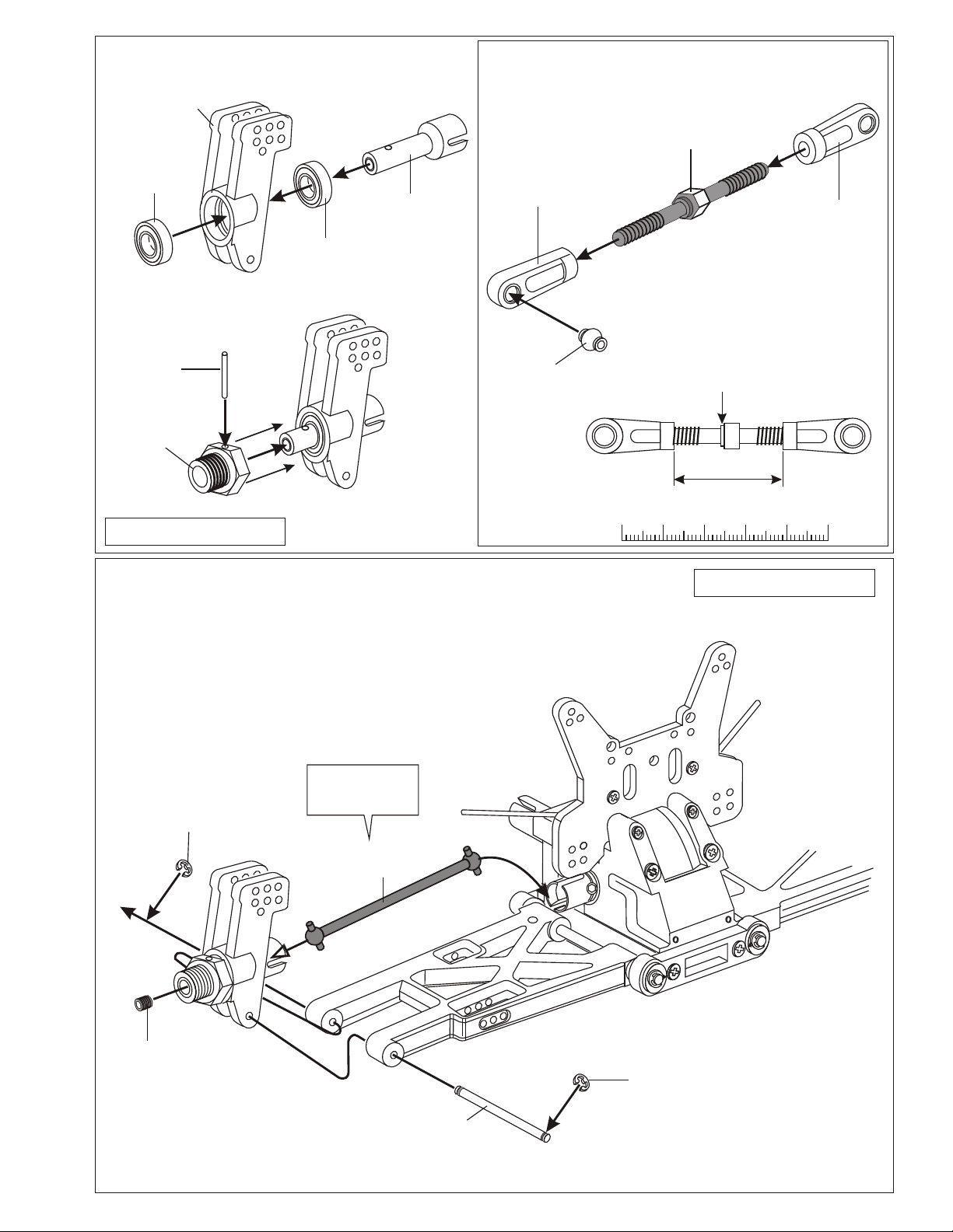
This rear pivot ball kit is suitable for those who already have "ULTRA GTP" car kit.
ASSEMBLY OF THE NEW FRONT LOWER ARM
* Follow these instructions to assemble this kit.
REPLACE THE OLD FRONT LOWER ARMS WITH
1
THE NEW ARMS.
36870
4x10mm
Set Screw
R
36890
Front Lower
Arm
* A 4 x 10mm set screw is used
to adjust the ride height.
* Approx 3mm.
4
ASSEMBLY OF THE UPPER ARM SHAFT
AND THE CASTER ADJUSTER
R
2
REMOVE THE FRONT STABILIZER
AND PARTS BAR FROM YOUR CAR.
90021
3mm
E-Ring
* Insert drive shaft
before assembly.
36670
Caster Angle
Adjuster
Assembly of the right and left hand side
are the same.
1
0
INSERT THE NEW FRONT
3
LOWER ARM SHAFT.
90021
3mm
E-Ring
31301
4x80mm
Lower Arm
Shaft
RR
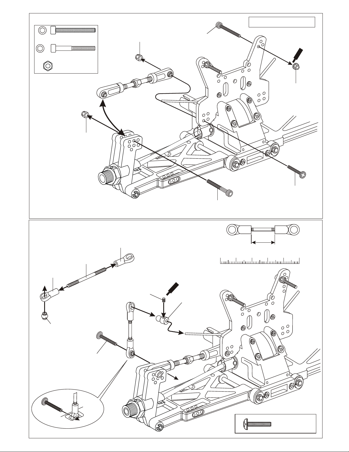
ASSEMBLY OF THE ANTI-ROLL BAR
* Builds two sets of anti-roll bars for the front and rear.
31308
31302
Anti-Roll Bar
Mount
(Left)
Anti-Roll Bar
3x3mm
Set Screw
31302
Anti-Roll Bar
Mount
(Right)
31308
Anti-Roll Bar
3x3mm
Set Screw
1
0
90021
3mm
E-Ring
30152
Upper arm Shaft
* Insert into cap.

ASSEMBLY OF THE REAR HUB
* Use the ball bearings and
rear drive shaft from your car kit.
31304
Rear Hub
36053
8x16mm
Ball bearings
31306
12mm
Alum. Hex Nut
36082
Rear
Wheel Shaft
31307
11mm
Pivot Ball
* Make sure the pivot ball
move smooth.
Assembly of the right and left hand side
are the same.
*Use the 4mm set screw
from your kit.
36870
4mm
Set Screw
31303
Rear
Lower Arm
36053
8x16mm
Ball bearings
5mm
Hex Wrench
31305
Ball Washer
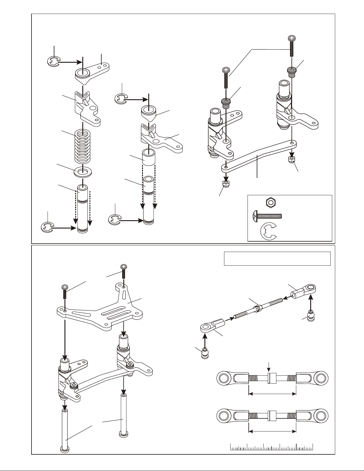
ASSEMBLY OF THE SUSPENSION ARMS ONTO
REAR GEAR BOX
* Use the parts that come
with your kit.
* Insert rear drive shaft
before assembly.
36055
Drive Pin
36089
Rear Drive
Shaft
90021
3mm
E-Ring
31301
Arm Shaft
* A 4 x 10mm set screw is used
to adjust the ride height.
Assembly of the right and left hand side
are the same.
* Remove the stabilizer and
parts from your car.
90021
3mm
E-Ring
Rear Wheel
Toe-in Adjuster
* Approx 3mm.
1
Degree
Fig.1
* Set triangle marks in
the direction shown
in Fig.1.
1.5
Degree
90026
5x5mm
Set Screw
* Do not r tighten
5x5mm set screw
over tighten.
*Use the upper arm and
screw from your car.
3mm
Nylon Lock
Nut
Plastic Washer
(Use 2 pcs)
36040
Upper Arm
3mm
Nylon Lock
Nut
90021
3mm
E-Ring
90019
3 x 25mm
Cap Screw
90019
3 x 25mm
Cap Screw

ASSEMBLY OF THE FRONT ANTI-ROLL BAR
( FRONT)
RR
31302
Anti-Roll
Bar Adjuster
1
0
( REAR)
REAR WIDTH SETTING
31302
Anti-Roll
Bar Adjuster
31302
Anti-Roll
Bar Adjuster
31302
Anti-Roll
Bar Adjuster
3x16mm
Screw
3x16mm
Screw
Turn
ASSEMBLE THE FRONT AND REAR GEAR BOX ONTO YOUR CAR AS USUAL.
SETTING GUIDE
REAR CAMBER SETTING
*Turn the anti-roll bar adjuster
keeping both side at the same
angle.
* Keep the ball of the anti-roll bar
central.
Turn
Changing the angle of the anti-roll bar
will change the strength of the arms.
Anti-roll strength became weaker
Turn
Anti-roll strength became stronger
Adjust A and B to the same .
Adjusting B longer will make the rear tires
toe-in (Positive).
Adjusting A longer will make the rear tires
toe-out (Negative).
0 0
- -
+ +
A A
B B
C C'
C.L
Item No.
Description
* Use a 2.5mm hex wrench to adjust
the rear track width.
31308 Anti-Roll Bar 1 set
31301 4x80mm Arm Shaft 2 pcs
31302 Anti Roll Bar Mount / Adjuster 1 set
36890 Front Lower Arm 1 set
31303 Rear Lower Arm 1 set
Qty
length
PARTS LIST
The rear camber adjustment can be make by changing the length
of the upper rod.
Making the upper rod longer will make the camber positive.
Making the upper rod shorter will make the camber negative.
0
Upper Rod
- -
Item No.
+ +
Description
0
Qty
31304 Rear Hub (Pivot Ball Type) 2 pcs
31305 Ball Washer 4 pcs
31302 Anti Roll Bar Mount / Adjuster 1 set
31306 Alum. Hex Nut 4 pcs
31307 Pivot Ball 2 pcs.
 Loading...