


IMPORTANT-READ THIS BEFORE RUNNING
1.Before Starting
•Please read manual carefully (With a parent, guardian or a responsible adult if necessary).
TOOLS NOT INCLUDED IN THE KIT
Included Item
s
1.5mm Allen Wrenc
h
2mm Allen Wrenc
h
2.5mm Allen Wrenc
h
Cutte
r
Curved Scissors
Craft Knife
Precision Caliper
Needle Nosed Pliers
Equipment Neede
d
2.While Operating
•Any running area you choose must be dry. Do not run vehicle near any water or wet areas.
•Do not run on public streets. It is very easy to have the car run over or be damaged by hitting the curb.
•Do not operate the car in tight confined places. The vehicle is very fast and will easily hit something.
•Do not run near people or animals. The car is very fast and could easily seriously injured someone.
•Do not operate the car at night. You will not be able to drive it safely.
3.Before Operating
•Make sure that all screws and nuts are properly tightened.
•Always use fresh batteries for your transmitter and receiver before running the car. If the radio does
not have full control of the car with steering, throttle and brake. Do not run it until corrected. Failure
to correct this will result in possible injury and damage to the car or property.
•Please confirm the steering and throttle is at neutral position.
4.Check Your Vehicle After Runing
•Turn OFF receiver first, then turn OFF transmitter. This will prevent the car from losing control.
•After running radio controlled car, it is necessary to perform routine maintenance.
5.Battery Safety
•Please be careful when handling the battery. It will be hot after running. If the wire is frayed, a short
circuit can cause a fire.
WARNING: To avoid a possible fire hazard, always unplug the battery. Do not leave your vehicle
unattended with the battery plugged.
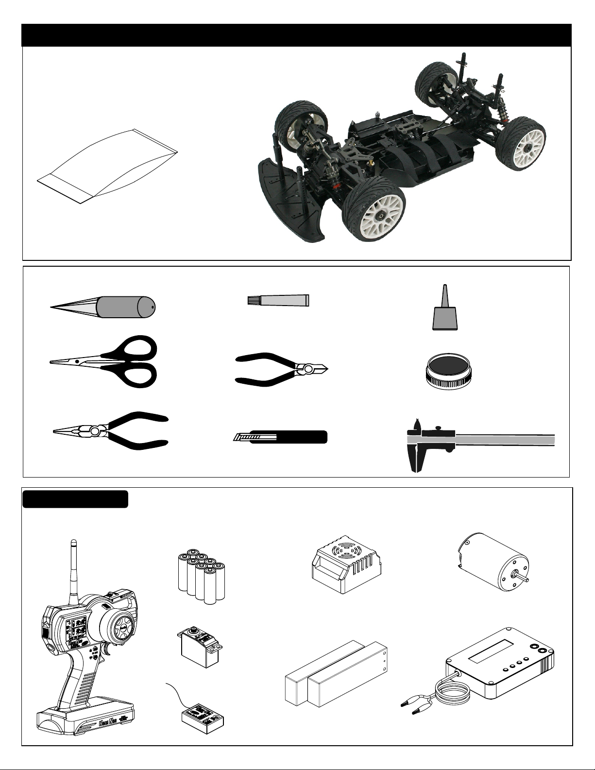
Components
Parts Bag
OVERVIEW
OVERVIEW
Radio Control Car
TOOLS NOT INCLUDED IN THE KIT
Screw Cement
Body Reamer
Curved Scissors
Needle Nosed Pliers
Equipment Needed
Transmitter
Cutter
Craft Knife
UM-3 "AA" type Batteries
( 8pcs )
Screw Cement
CA
Instant Cemment
GEAR
GREASE
Gear Grease
Precision Caliper
Servo
Receiver
Brushless Electric
Speed Controller
7.4V L i-Po Battery
(Hard Case)
Brushless Motor
L Battery Chargeri-Po

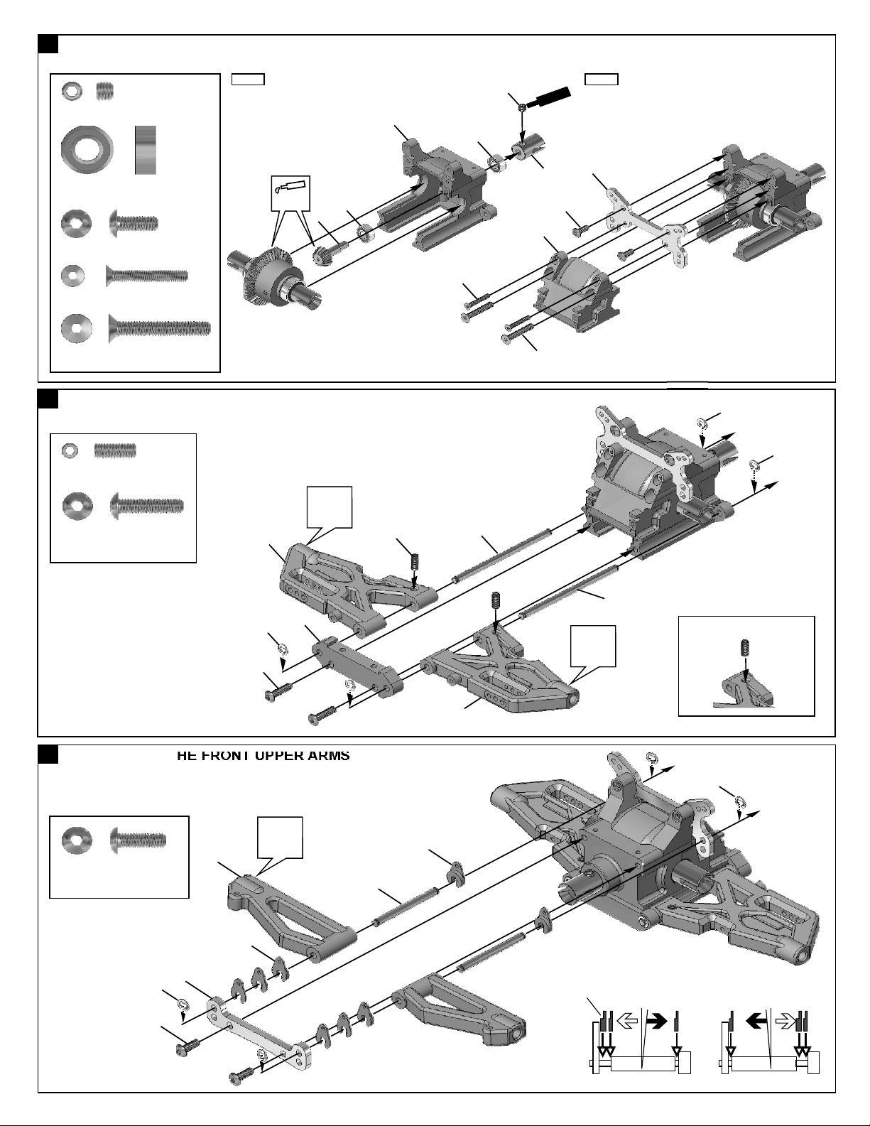
1
ASSEMBLY OF THE FRONT AND REAR DIFF.
Builds two differentials for front and rear.
Step 1
30779
2x12.8mm Pin
94034
4x4mm
Set Screw
30777
P5 O-Ring
30620
7x19x6mm Ball Bearing
2
ASSEMBLY OF THE FRONT AND REAR DIFF.
30776
4x10mm Washer
.....x4
.....x2
30620
Oil
30901
.....x4
.....x4
Step 1 Step 2
30773
.....x8
30751
30769
30776
30777
30779
30769
30779
Step 2
30769
30777
Tighten
3x12mm
Oil
30620
30751
30779
4X4mm
Builds two differentials for front and rear.
Tight the diff. screws in this order.
1
30901
3
94004
3x12mm
Hex Screw
30773
4mm
Cross Pin
3
ASSEMBLY OF THE FRONT AND REAR BEVEL GEARS
30121
4x3x3mm
Chromed Tube
30121
3x5mm Screw
.....x8
.....x4
.....x8
.....x8
*Push 3mm tubes into the
Step 1 Step 2
holes of the diff. Case.
D
i
ff.
O
il
*Put the diff. oil
approx 80%.
4
Builds two differentials for front and rear.
30121
2
30121
30121
3x5mm
1
4
ASSEMBLY OF THE GEAR BOX AND FRONT SHOCK STAY
Step 1 Step 2
94036
5x4mm Set Screw
30630
6x13x5mm Ball Bearing
94009
4x10mm Hex Screw
94023
3x25mm Flat Head Screw
94029
4x25mm Flat Head Screw
5
ASSEMBLY OF THE FRONT LOWER ARMS
36870
4x10mm Set Screw
94011
4x16mm
Hex Screw
.....x2
.....x2
.....x1
.....x2
.....x2
.....x2
.....x2
36890
Apply
Grease
30130
Ensure
Free
Movement
30630
30010
4x10mm
30630
3x25mm
36171
5x5mm
S
Ce
30082
30010
4x25mm
ew
cr
ent
m
4x10mm
30262
3mm
3mm
30160
3mm
4x16mm
6
ASSEMBLY OF THE FRONT UPPER ARMS
Ensure
Free
Movement
36905
94010
4x12mm
Hex Screw
3mm
36900
.....x2
30654
36640
36905
36890
Ensure
Free
Movement
Caster Adjuster
36171
*Caster angle will
become bigger.
*A 4x10mm set screw is used
to adjust the ride-height.
3mm
*Caster angle will
become less.
4x12mm
2
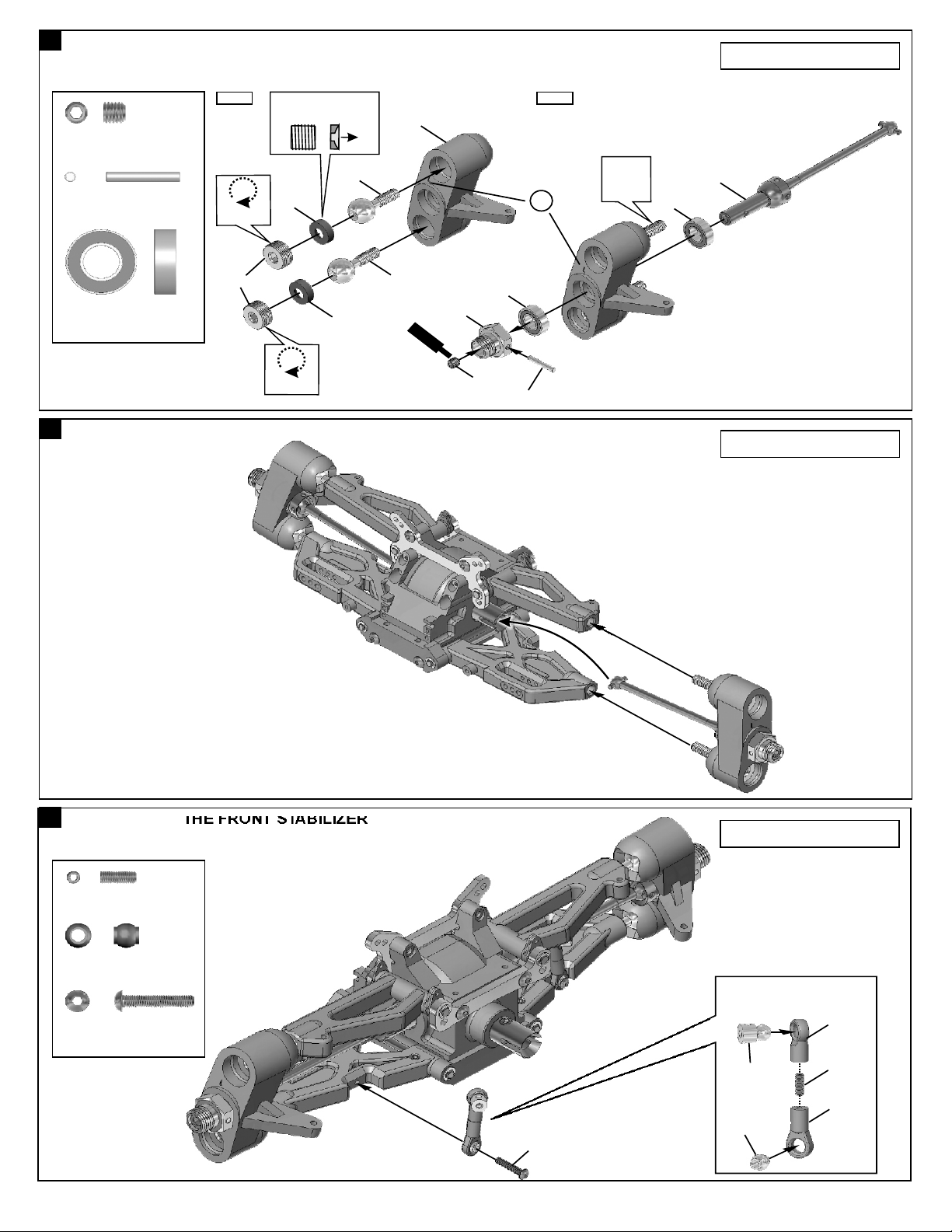
7
ASSEMBLY OF THE FRONT KNUCKLE ARMS
Assembly for both right and left side.
*Notice the direction of the
plastic washer.
36903
36901
S
Cem
36053
30656
cr
e
w
e t
n
5x4mm
94036
5x5mm
Set Screw
36055
2.5x16.8mm Pin
36053
8x16x5mm Ball Bearing
8
ASSEMBLY OF THE FRONT KNUCKLE AND FRONT SUSPENSION ARMS
.....x2
.....x2
.....x4
Do Not
Over Tighten
36904
36905
Do Not
Over Tighten
36903
36905
Step 2Step 1
L
36055
Ensure
Free
Movement
36052
36053
Assembly for both right and left side.
9
ASSEMBLY OF THE FRONT STABILIZER
3x8mm
Set Screw
30403
6mm Ball
3x16mm
Hex Screw
.....x2
.....x2
.....x2
* Put the drive shaft
into cup joint before
assembly.
94005
3x16mm
Assembly for both right and left side.
Makes two rods for left and right
hand-side.
40029
30341
30403
94035
3x8mm
40199
3

10
ASSEMBLY OF THE FRONT STABILIZER
3x3mm
Sc
C
re
m
e ent
w
94033
3x3mm
Set Screw
94002
3x8mm
Hex Screw
11
ASSEMBLY OF THE SERVO SAVER
94041
M3 Nylon Nut
.....x2
.....x2
.....x2
Step 1 Step 2 Step 3
36743
6mm
94040
3x8x0.8mm
3x8mm
Ensure
Free
Movement
30261
36740
36740
36743
6mm
36740
36740
Scr
C
ew
em nte
3x3mm
3x16mm
36742
36743
6mm E-Ring
94005
3x16mm
Hex Screw
12
ASSEMBLY OF THE SERVO SAVER AND THE STEERING TIE-ROD
94003
3x10mm
Hex Screw
94021
3x15mm
Flat Head Screw
.....x4
.....x2
3x10mm
Step 1
30272
.....x3
.....x2
36741
8x12x1mm
30361
36743
6mm
3x10mm
36743
6mm
34014
Step 2
36850
36700
36740
30361
36790
3x15mm
40038
Ensure
Free
Movement
3x15mm
30658
M3
Nylon Nut
30380
1:1
*Approx. 33.5mm
* 33. 5mm¬ù
4

13
ASSEMBLY OF THE SERVO SAVER ONTO THE FRONT GEAR BOX
94041
M3 Nylon Nut
.....x2
3x15mm
94003
3x10mm
Hex Screw
94021
3x15mm
Flat Head Screw
14
ASSEMBLY OF THE GEAR BOX AND REAR SHOCK STAY
94036
5x5mm Set Screw
30630
6x13x5mm Ball Bearing
94005
3x16mm Hex Screw
.....x2
.....x2
.....x1
.....x2
.....x2
3mm
Step 1 Step 2
30010
Apply
Grease
30130
30630
40039
3x15mm
30630
5x5mm
30082
30010
w
e
t
r
c
en
S
e
C m
3x16mm
3mm
34009
3x10mm
40039
3mm
94022
3x18mm Flat Head Screw
94029
4x25mm Flat Head Screw
15
ASSEMBLY OF THE REAR LOWER ARMS
36870
4x10mm Set Screw
94027
4x16mm
Flat Head Screw
.....x2
.....x2
.....x2
.....x2
3mm
4x16mm
34035
30351
Ensure
Free
Movement
3x18mm
*A 4x10mm set screw is
used to adjust ride-height.
4x10mm
36171
4x25mm
Ensure
Free
Movement
3mm
3mm
34035
5

16
ASSEMBLY OF THE REAR SUSPENSION ARMS
Assembly for both right and left side.
94036
5x5mm
Set Screw
94001
3x4mm
Hex Screw
36053
8x16x5mm Ball Bearing
36055
2.5x16.8mm Pin
17
ASSEMBLY OF THE REAR SUSPENSION ARMS
36850
7mm Ball
94041
3mm
Nylon Nut
94006
3x18mm
Hex Screw
94008
3x25mm
Hex Screw
.....x2
.....x2
.....x4
.....x2
Step 1 Step 2
.....x4
.....x4
.....x2
.....x2
36850
40065
*Approx. 21mm
36861
1:1
3x4mm
40065
36850
34055
3x18mm
40028
36082
34035
3x25mm
36053
Ensure
Free
Movement
3mm
36081
36053
36055
5x5mm
36054
3mm
18
ASSEMBLY OF THE REAR STABILIZER
94035
3x8mm
Set Screw
30403
6mm Ball
94006
3x18mm
Hex Screw
.....x2
.....x2
.....x2
Makes two rods for left and right
hand-side.
30403
30341
Assembly for both right and left side.
Assembly for both right and left side.
40029
3x8mm
40199
3x18mm
6

19
ASSEMBLY OF THE REAR STABILIZER
94033
3x3mm
Set Screw
.....x2
3x3mm
r
Cem n
w
eSc
t
e
S
c
re
e
w
menC
3x3mm
t
94022
3x8mm
Hex Screw
.....x2
Ensure
Free
Movement
34027
3x8x0.8mm
3x8mm
20
ASSEMBLY OF THE REAR BODY POST
Step 1 Step 2
M2 Nut
94041
M3 Nylon Nut
2x18mm
Screw
.....x2
.....x2
.....x2
31159
33011
Choose the correct body
33011
post pin hole for your body.
3mm
3mm
33011
31159
3x16mm
2mm
Sc
C en
Step 1
33020
33010
3x16mm
t
ew
r
m
e
c S
rew
mCe
ent
2x18mm
10mm
35222
5
0
ew Scr
t
en
m
Ce
10 15
94005
3x16mm
Hex Screw
21
ASSEMBLY OF THE ONE SPEED TRANSMISSION INTO THE CENTER MOUNT
94036
5x5mm
Set Screw
94002
3x8mm
Hex Screw
.....x2
.....x3
.....x4
5x5mm
30201
Step 2
30110
30170
S
cr
Cem
ew
e
n
t
e
r
nt
c
e
S w
m
e
3x8mm
C
5x4mm
30620
Step 3
30620
30170
w
t
c e
S r
me
e n
C
5x4mm

22
ASSEMBLY OF THE SINGLE SPEED MOUNT
Step 1
94033
3x3mm
Set Screw
94004
3x12mm
Hex Screw
94005
3x15mm
Hex Screw
23
ASSEMBLY OF THE FRONT GEAR CASE ONTO CHASSIS
94019
3x10mm
Flat Head Hex Screw
.....x1
.....x4
.....x2
.....x2
3x12mm
30652
TOOLS NOT INCLUDED IN THE KIT
Included Item
s
1.5mm Allen Wrenc
h
2mm Allen Wrenc
h
2.5mm Allen Wrenc
h
Cutte
r
Curved Scissors
Craft Knife
Precision Caliper
Needle Nosed Pliers
Equipment Neede
d
34056
94026
4x12mm
Flat Head Hex Screw
94023
3x25mm
Flat Head Hex Screw
.....x2
.....x2
3x25mm
24
ASSEMBLY OF THE CENTER DIFF. ONTO CHASSIS
*Insert the drive shaft into
the cap joint before assembly
center diff. onto chassis.
94027
4x16mm
Flat Head Hex Screw
.....x4
34050
3x10mm
4x12mm
4x16mm
4x16mm

25
ASSEMBLY OF THE REAR GEAR CASE ONTO CHASSIS
94027
4x16mm
Flat Head Hex Screw
94023
3x25mm
Flat Head Hex Screw
26
ASSEMBLY OF THE STONE GUARD ONTO CHASSIS
94019
3x10mm
Flat Head Hex Screw
.....x4
.....x2
.....x6
*Insert the drive shaft into
the cap joint before assembly
rear gear box onto chassis.
34080
34050
4x16mm
4x16mm
3x25mm
3x10mm
ASSEMBLY OF VELCRO STRAP INTO BATTERY CASE
27
Step 1
30662
30663
3x10mm
3x10mm
Step 2

28
ASSEMBLY OF THE ELECTRIC SPEED CONTRTOL
Double side tape
(Not Included)
29
ASSEMBLY OF THE BATTERY TRAY BRIDGE ONTO BATTERY CASE
3x8mm
30662
3x10mm
Electronic Speed Control
(not included)
94002
3x8mm
Hex Screw
94003
3x10mm
Hex Screw
30
ASSEMBLY OF THE ELECTRIC SPEED CONTROL WIRE INTO RADIO CASE
Step 1
.....x2
.....x2
30662
30662
Step 2

31
ASSEMBLY OF THE STEERING SERVO ONTO RADIO CASE
3x10mm
3x10mm
3x8x0.8mm
94003
3x10mm
Hex Screw
94040
3x8x0.8mm
Washer
32
ASSEMBLY OF THE SERVO WIRE INTO RADIO CASE
.....x4
30662
.....x4
3x8x0.8mm
Steering Servo
(Not Included)
33
ASSEMBLY OF THE BATTERY CASE ONTO CHASSIS
94019
3x10mm
Flat Head Hex Screw
94026
4x12mm
Flat Head Hex Screw
94053
5x10mm
Flat Head Hex Screw
.....x3
.....x1
.....x2
5x10mm
3x10mm
3x10mm

34
ASSEMBLY OF THE RADIO CASE ONTO CHASSIS
94019
3x10mm
Flat Head Hex Screw
35
ASSEMBLY OF THE RECEIVER INTO RADIO CASE
Please carefully read the Receiver Instruction
Manuals before installation.
94002
3x8mm
Hex Screw
.....x4
*Plug in your speed controller
wire to CH2 and steering servo
wire to CH1 of your receiver.
Receiver(not included)
.....x2
3x10mm
3x10mm
Antenna Wire
40642
37410
30560
3x8mm
30662
30662
Do not cut or shorten antenna wire.
Step detail
Use a screwdriver to straighten the antenna wire so
it is easier to insert into antenna tube.
36
ASSEMBLY OF THE STEERING ROD ONTO STEERING SERVO
SAVOX
Sanwa/Airtronics
S J F
Choose the right servo horn adapter for your servo.
94004
3x12mm
Hex Screw
30411
6mm Ball Socket
JR
.....x2
.....x2
Futaba
HiTech
H
3x12mm
30401
30411
30661
30411
30401
38280(3x36mm)
3x12mm
Use the screw
provided with
your servo.
30661
13
Approx. 19mm

37
MOTOR INSTALL
Electric Motor
(Not Included)
94034
4x4mm
Set Screw
38
MOTOR INSTALL
94038
3x12mm
Cap Screw
.....x1
.....x2
4x4mm
30670-(12T)
30664-(13T)
30665-(14T)
30666-(15T)
30667-(16T)
30668-(17T)
3x12mm
Do Not
Over Tighten
Step detail
*Approx. 20mm
94040
3x8x0.8mm
Washer
39
ADJUST MOTOR AND SPUR GEAR MAINTENANCE
.....x2
PUSH
Adjust the motor position to get proper gear mesh.
To get a perfect gear mesh , place a piece of notebook paper
between the gears and tighten the motor mount screws.
The spur gear will strip if the gear mesh is wrong.
Tighten
Tighten
Ensure
Free
Movement
3x8x0.8mm
Tighten the 3x12mm screw
temporary.
EXTREMELY IMPORTANT
Notebook paper
Insert a piece of notebook paper between
spur gear and pinion gear to make correct
gear mesh.
14

40
BATTERY INSTALL
41
ASSEMBLY OF THE REAR SHOCKS
* Make 2 for Shocks for rear.
Step 1
2.5mm Nylon Nut
40090
3.5mm O-Ring
40090
1mm Washer
40090
2mm Washer
30403
6mm Ball End
.....x2
.....x4
.....x2
.....x2
.....x2
30403
40635
40090
40090
40643
Shock Plastic
Ball End
(Short)
40637
40090
2mm
40090
1mm
40737
Follow the manual instruction provided by ESC
manufacturer to install the wire.
Step 2
*Fit the o-ringinto groove before
assembly.
40636
40736
2.6x6mm
Washer
40638
2.6x6mm
Washer
2.5mm
40634
1. Pull down piston and
pour oil into shock
cylinder.
2.To remove air bubbles
by slowly moving
piston up and down.
*Fill the shocks
with oil approx 90%.
If use hard case battery , make a hole as picture shown.
3. Pull down piston,
attach pressure top
and shock oil
overflow with tissue
paper.
40643
40640
40633
CORRECT SHOCK ASSEMBLY
Carefully screw the
shock shaft into the
bottom of the plastic
ball and until the
distance between the
ballend and the shock
body is 15mm for the
front.
N.B. Do not over tighten
as the plastic will strip.
8mm
m
m
5
1
15mm
2.6x6mm Washer
42
ASSEMBLY OF THE REAR SHOCKS
* Make 2 for Shocks for front.
2.5mm Nylon Nut
40090
3.5mm O-Ring
40090
1mm Washer
40090
2mm Washer
30403
6mm Ball End
2.6x6mm Washer
.....x4
.....x2
.....x4
.....x2
.....x2
.....x2
.....x4
Step 1
30403
40635
40090
40090
40643
Shock Plastic
Ball End
(Short)
40637
40090
2mm
40090
1mm
40632
*Fit the o-ringinto groove before
assembly.
40636
40054
2.6x6mm
Washer
40638
2.6x6mm
Washer
2.5mm
40634
Step 2
1. Pull down piston and
pour oil into shock
cylinder.
2.To remove air bubbles
by slowly moving
piston up and down.
*Fill the shocks
with oil approx 90%.
3. Pull down piston,
attach pressure top
and shock oil
overflow with tissue
paper.
40643
40640
40633
0 20
30
CORRECT SHOCK ASSEMBLY
Carefully screw the
shock shaft into the
bottom of the plastic
ball and until the
distance between the
ballend and the shock
body is 32mm for the
front.
N.B. Do not over tighten
as the plastic will strip.
2mm
3
0 20
30
4010
4010

43
ASSEMBLY OF THE FRONT AND REAR SHOCK SPRING
* Assemble 2 Sets for Front * Assemble 2 Sets for Rear
30274
40643
44
ASSEMBLY OF THE FRONT SHOCK ABSORBER
94041
3mm
Nylon Nut
94007
3x20mm
Hex Screw
90018
3x25mm
Cap Screw
.....x2
.....x2
.....x2
Do Not
Over Tighten
94040
3x8mm
3mm
30275
40643
3x25mm
40531
3x20mm
45
ASSEMBLY OF THE REAR SHOCK ABSORBER
94041
3mm
Nylon Nut
94007
3x20mm
Hex Screw
90018
3x25mm
Cap Screw
.....x2
.....x2
.....x2
Do Not
Over Tighten
3x8mm
3mm
Assembly for both right and left side.
40531
3x25mm
3x20mm
Assembly for both right and left side.
16

46
ASSEMBLY OF THE FRONT BUMPER
Choose the correct body
post pin hole for your body.
33011
34091
34090
33011
33011
4x12mm
Contact
Adhesive
M2 Nut
2x18mm
Screw
94010
4x12mm
Hex Screw
94011
4x16mm
Hex Screw
47
ASSEMBLY OF THE TIRES AND WHEELS
.....x2
.....x2
.....x2
.....x4
86050
2mm
33011
31159
2x18mm
Step 2Step 1
4x16mm
*Pull back the tire bead slightly and spot glue in four spots as
shown. When dry, glue the rest of the wheel between the spots.
Repeat the procedure on the other side of the wheel until fully
glued.
Contact
Adhesive
86026
86059
Inner Sponge
(WidE)
86059
Inner Sponge
(Narrow)
48
ASSEMBLY OF THE WHEELS ONTO THE FRONT KNUCKLE AND REAR HUB
40550
40550
Wheel Nut
.....x4
40550
10239
INST
G
NTA
L
UE
Assembly for both right and left side.
Tire and wheel
assembly.
40550
40550

OPERATING YOUR MODEL SAFELY
Before Running Engine Start-Up
Your radio control model can
move at high speed and
therefore can cause injury to
people or damage property.
It is your responsibility to
operate your model safely.
For radio equipment, refer to
the manual included with the
radio.
Check that all screws and nuts
arc tight.
If the model begins to operate
by itself, there is someone
else on your frequency.
Do not try to operate your
model under these conditions
for it may go out of control.
For engine use, refer to the
manual included with the engine.
To prime the engine with fuel,
press down the primer button.
Attach one clip to the glow plug's
end and the other clip to one of
the cylinder cooling fins.
While Running
Check that the model turns in
proportion to the amount you
move the steering control of the
transmitter.
Check that the speed of the
model changes in proportion to
the amount you move the speed
control of the transmitter.
After Running
Cautions for Safety
Do not run your model through
water. This may cause rust or
electrical problems.
If model does not operate
correctly stop it and find the
cause.
Check the batteries.
Fill in the fuel.
Fully extend
transmitter antenna.
Switch on transmitter.
OFF
ON
Switch on receiver.
Quickly. pull the starter rope
(to start the engine).
Adjust by screwing the needle
little by little.
Remove the clips from the engine.
By pushing with your fingers the
air cleaner, interrupt the engine
Switch off receiver.
Switch off transmitter.
OFF
Proper maintenance extends the
life of the model.
ON
After each run, the model is hot.
Beware of getting burned.
Keep hands and tools away from
moving parts.
Never throw burning, gleaming
or smouldering things into fuel
cans even if these happen to be
empty.
This is very dangerous to life! I!
Use genuine parts.

SETTING GUIDE
FRONT TOE-IN AND TOE-OUT SETTING
NEUTRAL POSITION
TOE-IN
TOE-OUT
Rear
Toe-In
TOE-OUT
Steering Rod
Rear
Toe-In
Use a 5mm allen wrench to adjust toe-in for front .
Adjust the length of the front steering rod to change the toe angle.
(Front)
Making the steering rod longer will make the front tires become
toe-in.
Response will be slower and will over steer.
Making the steering rod shorter will make the front tires become
toe-out.
Response will be quicker and will under steer.
We recommended adjusting the front toe-out to 1.5 degrees.
4'5'5.5'7mm Allen Wrench
Use rear tor-in adjuster.
1
Degree
Fig.1
1.5
Degree
Set triangle marks in
the direction shown
in Fig.(1)
FRONT AND REAR CAMBER ANGLE SETTING
Note: Place the model car on a flat surface. Raise the chassis to it's maximum clearance
before the wheels leave the ground.
Adjust the length of the front and rear upper arms so that the wheels are right angles to the
ground.
(FRONT)
+
Positive
The front camber adjustment can be made by moving the 14mm
steering ball at the front upper arms on knuckles, clockwise or
anticlockwise.
-
Negative
-
We suggest using 1.5 degress of negative camber for the front.
+
+
Positive
Adjust the length of the turnbuckle on
can be change the rear camber.
We suggest using 2 degress of negative camber for the rear.
FRONT AND REAR SHOCK ANGLE SETTING
1 2
Firm
(REAR)
Soft
(FRONT)
-
Negative
(REAR)
Soft
¡¯Use 2. 5mm hex wr ench
¡@t o adj ust uppe r ar m bal l
¡@i n f r ont .
Turnbuckle
the rear upper arms
Firm
3
1 2
-
+
3
1 2
Soft
Firm front suspension, less steering.
Soft front suspension, more steering.
Firm
12
Soft
Firm front suspension, less steering.
Soft front suspension, more steering.
Firm

OFNA DESCRIPTIONS RETAIL OFNA DESCRI PTION RETAIL
30010 MAIN GEAR CASE, QUICK CHANGE 14.95 36680 STIFFENER SUPPORT,7mm F&R 3PC. 8.95
30080 JOINT CAP, 6mm, 2 PCS. 9.95 36690 UPPER BALL END, 7mm 6PCS 6.95
30082 JOINT CAPS, 6mm, 2 PCS. 9.95 36700 STEERING BALL END, 7mm, 8PCS. 6.95
30202 CENTER, DIFF ADAPTER 1.95 36741 SPRING, SERVO SAVER NEW HARD 3.95
30262 SHOCK TOWER FRONT GTP 2 H.C. 7.95 36742 BUSHING, SERVO SAVER 1.95
30272 FRONT PLATE JOINT H.C. GTP 2 7.95 36743 6mm E-CLIP, SERVO SAVER 2.95
30273 STABILIZER BAR 2.5mm GTP 2 3.95 36790 4x46MMTURNBUCKLES,4PCS. 10.95
30274 SPRING FRONT GTP 2 1.8x6T 5.95 36861 5x40mm TURNBUCKLES, 2 PCS BLK 6.95
30275 SPRING REAR GTP 2 1.8x10T 5.95 36890 FRONT LOW ER ARMS (mbx4) PAIR 13.95
30110 GEAR, SPUR(NYLON) ULTRA 7.95 36900 FRONT UPPER ARMS (mbx4) PAIR 11.95
30120 GEAR, BEVEL 44T, STOCK 10.95 36901 KNUCKLE, PIVOT BALL (mbx4) 2PC 13.95
30121 MISC BEVEL MOUNTING HARDWARE 1.95 36903 PIVOT BALLS, STEEL (mbx4) 4PCS 7.95
30130 GEAR, BEVEL PINION 14.95 36904 14mm ALUM. NUT (mbx4) 4 PCS 9.95
30160 FRONT PLATE, ARM PIN HOLDERS 4.95 36905 W ASHER PLASTIC, 14mm NUTS 5.95
30201 CENTER, DIFF MOUNT, NEW TYPE 13.95 37410 BODY CLIPS, 10 PCS. SMALL JL10 3.95
30341 BALL END WITH COLLAR, 6mm 3.95 38280 3x36mm TURNBUCKLE 5.95
30351 REAR ARM HOLDER 3PCS 3.95 40028 DOG BONES, 93MM PAIR LX1 19.95
30361 SERVO SAVER SHAFT 5.95 40029 BALL ENDS, PLASTIC, ANTI-ROLL 3.95
30380 SERVO SAVER POSTS, 2 PCS. 4.95 40038 BALLS, 7MM 4PCS. 9.95
30401 STEERING ENDS, PLASTIC 6 PCS. 2.95 40039 CONE, ALUM. 3MM, 4PCS. 3.95
30403 6mm BALL, STEEL (NO COLLAR) 4.95 40055 SHAFTS,3.5m REAR SHOCKS, 2PCS 7.95
30411 6mm BALLS w/COLLAR,STEERING 6P 4.95 40060 NYLOK NUT, 2.5, PISTON NUT, 4 4.95
30482 SPACERS, RAISE ENGINE MOUNT 4.95 40065 BALL ENDS, PLASTIC, REAR UPPER 4.95
30620 BEARING KIT, 7x19mm , 6 PCS. 29.95 40090 SEALS,SHOCK REBUILD, 9.5 X-1 7.95
30630 BEARING KIT, 6x13mm 12PCS. 59.95 40199 STEERING BALL END,PLASTIC, 6mm 7.95
30649 SHOCK TOW ER REAR LX1 H.C. 11.95 40531 SHOCK BALL POST/ONE-PIECE/TOP 9.95
30653 CENTER TOP PLATE LX1 H.C. 6.95 40550 W HEEL NUT 5mm 4.95
30654 HOLDER, UPPER ARM ALU. LX1 H.C 7.95 40632 SHOCK BODY FRONT 13mm 24.95
30656 W HEEL HUB, LX1 H.C. 11.95 40633 SHOCK CAP, 13mm 18.95
30658 SERVO SAVER CONNECTOR H.C. LX1 6.95 40634 SHOCK SPRINGS ADJUSTER, 13mm 9.95
30659 FRONT TOP PLATE H.C. LX1 6.95 40636 O-RING 15x1mm 3.95
30661 SERVO HORN HEAVY DUTY BLACK 4.95 40637 FELT FOR RED DUST, 13mm SHOCK 1.95
30662 BATTERY CASE,RX BOX LX-1e 19.95 40638 SHOCK PISTON 13mm 7.95
30663 BATTERY VELCRO STRAPS LX-1e 9.95 40640 SHOCK, PRESSURE TOP, ORANGE 5.95
30665 PINION 14T 5MM SHAFT 12.95 40642 ANTENNA , FIXING NUT 2.95
30673 ARM HOLDER FR H.C. LX-1 12.95 40643 PLASTIC SHOCK PARTS,13mm SHOCK 9.95
30674 SERVO SAVER PLASTIC SET LX-1 7.95 40736 SHOCK SHAFT DM-1 7.95
30675 CNC MOTOR MOUNT LX-1e 29.95 40737 SHOCK BODY, 13mm DM-1 24.95
30751 CASE, DIFF (K), FRONT or REAR 9.95 41033 STONE GUARDS X2T 15.95
30761 CASE, DIFF CASE (K), CENTER 9.95 86023 17mm W HEELS, V SPOKE, BLACK PK 19.95
30769 DIFF GEAR,SILVER BEVEL,SET 4mm 14.95 86024 17mm WHEELS, V SPOKE, BLUE PK 19.95
30773 CROSS PIN AXLES, 4mm STEEL 3.95 86025 17mm W HEELS, V SPOKE, LIME PK 19.95
30776 W ASHER, 4x10x0.2mm 4PCS. 1.95 86026 17mm WHEELS, V SPOKE, WHITE PK 19.95
30777 SEAL, O-RING (LARGE) DIFF CASE 3.95 86027 17mm W HEELS, V SPOKE,ORANGE PK 19.95
30779 MISC. PARTS, OLD DIFF & (k) 9.95 86028 17mm W HEELS, V SPOKE, GRAY PAK 19.95
30779 MISC. PARTS, OLD DIFF & (k) 9.95 86029 17mm W HEELS, V SPOKE, YEL PACK 19.95
30780 PINS, 2X12.8mm FOR DIF 2PCS 3.95 86030 17mm W HEELS, V SPOKE,CHROME PK 23.95
30901 CAP JOINT W/SHAFT F/R DIFF 11.95 86050 1:8 TIRE, SLICK w/o BELT, PAIR 19.95
30911 CAP JOINT W /SHAFT, BRAKE 11.95 86051 1:8 TIRE, SLICK with BELT,PAIR 35.95
31159 BODY CLIPS, CHROME 4.95 86052 1:8 TIRE,TREADED w/o BELT, PR. 19.95
31300 ANTIROLL BAR GTP FRONT & REAR 24.95 86053 1:8 TIRE,TREADED with BELT,PR. 35.95
33010 MOUNTING KIT, GTP 9.95 86059 FOAM STRIPS, INSERTS, LOW-PRO 9.95
33011 MOUNTING KIT, SEDAN (GTP) 12.95
34014 BRACE, FRONT CHASSIC,ULTRACOMP 3.95 30664 PINION 13T 5MM SHAFT 12.95
34027 ANTI-ROLL BAR KIT, U.COMP,LX1 3.95 30666 PINION 15T 5MM SHAFT 12.95
34050 CENTER BONES, ULTRA GT, 2PCS 15.95 30667 PINION 16T 5MM SHAFT 12.95
34054 SHAFT, REAR DOG BONE 93mm PR. 15.95 30668 PINION 17T 5MM SHAFT 12.95
34055 PINS, LOWER REAR ARMS 3x42.6mm 15.95 30774 CROSS PIN AXLES, 4mm ALUM 6PCS 9.95
34090 BUMPER, ULTRA SEDAN GTP/RALLY 12.95 31010 GEAR, BEVEL 44T, HD STEEL 28.95
34091 FOAM BUMPER, GTP/RALLY 15.95 31138 BODY, DTM M-TYPE CLEAR 64.95
34110 BEARING, 5x10, 2 PCS 6.95 31040 GEAR, SPUR, 51T STEEL 29.95
36052 CVA JOINTS,F/R WII&MBX95 8mmPR 49.95 31141 BODY, M-TYPE WITH DECALS 64.95
36053 BEARING, 8x16mm, PAIR 12.95 31144 BODY, V-GTP WITH DECALS 59.95
36055 PIN, 2.5x17mm, HEX HUBS, 4PCS 3.95 31295 REAR PIVOT BALL KIT,ULTRA GTP 54.95
36081 REAR UP-RIGHT (8mm BEARING) PR 12.95 33992 PCR FR STIFFNER BRACE ULTRA 24.95
36082 REAR AXLES, 8mm PAIR 10.95 33994 PCR UPPER FR ARM ULT 13.95
36100 CENTER DOG BONES,SET 86 & 90mm 16.95 33995 PCR STEERING LINK PLATE ULTRA 14.95
36170 REAR ARM PINS, 3mm 4PCS 7.95 33996 PCR UPPER PLATE, FRONT DIFF UL 15.95
36171 ARM PIN 4mm FRONT INSIDE LX1 5.95 33997 PCR CENTER DIFF. TOP PLATE ULT 15.95
36640 ARM SHAFT, 4mm, SHORT, 2PCS 9.95 41116 CNC ALUM. BALLS SET HARDCOATED 24.95
34306 ULTRA GTP2e PARTS LIST
LX-1e OPTION PARTS

BLANK

OWNER’S REGISTRATION CARD
OFNA Racing congratulates you on your purchase of our fine OFNA Product. With proper maintenance and handling this kit will provide many hours of enjoyment.
The registration card should be filled out and mailed to OFNA Racing within 10 days of purchase date.
In the event that the kit is incomplete or component parts are broken due to error in manufacturer, contact your
dealer from which you purchased the kit for replacement part or call OFNA at (949) 586-2910 for your nearest dealer
location. Other items such as radio and engine other covered by individual warranties.
IMPORTANT!
Please print or type, filling in the information listed below and mail immediately
MAIL TO:
OFNA RACING
7 VANDERBILT
IRVINE, CA. 92618
TEL: (949) 586-2910
Write in Your Model Name and Part Number
REGISTRATION CARD
RACER’S NAME TEL:( )
ADDRESS
CITY STATE ZIP
DEALER’S NAME TEL: ( )
ADDRESS
CITY STATE ZIP
OFNA
7 Vanderbilt
Irvine, Ca. 92618
 Loading...