

OFNA Racing Ultra Comp2 User Manual

INSTRUCTION MANUAL
• New Arms Design
• New Bumper
• Uses Less ”E” Clips
• 12mm X-1 Racer Shocks
Ultra LX Comp2 Rev:01
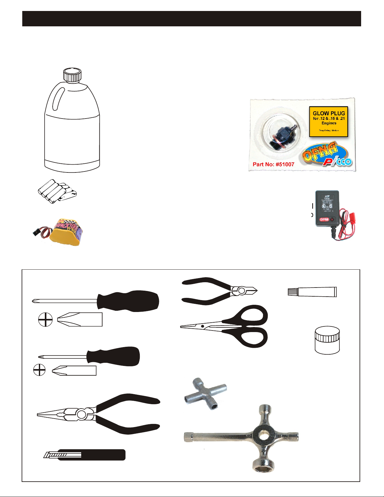
REQUIRED FOR OPERATION
THINGS NEEDED
Glow Fuel
20%
AA Batteries ( 12 pcs )
You will need to buy a few items to start the engine and run the car.
• Use 20% nitro CAR fuel. Do not use airplane or heli fuels, they will
over heat engine.
• Buy LONG glow plugs, like OFNA/PICCO Plug (#51007-cool or
51008-med). Use plugs without idle bar. Do NOT use plugs, like the
MC-59 or OS-8 or any short plug
In your box you will find..
• #10162 - Bottle, 250cc
• #10219 - Red “D” size glow heater
You need to get batteries for the radio transmitter and the car receiver
packs.
• Radio TX needs (8) eight AA batteries.
• Car needs (4) four AA Ni-cad batteries, Alkaline type batteries will
work, but braking will be reduced. The best is to use a 5 cell hump
pack for increased voltage..
Recommended Option:
#10212 NiHm Hump Pack,
see charger 10214.
TOOLS NOT INCLUDED IN KIT,
BUT NEEDED TO MAINTAIN YOUR CAR.
Phillips Type Screw Drivers ( L )
Phillips Type Screw Drivers ( S )
You may want to upgrade the car battery pack to a Ni-Cad or NiHm 5
cell type(600AE). This will give more run time. OFNA #10212
Cutter
91009
Curved Scissors
$5.95
Cross Wrench
#17109 $3.95
#10796 $3.95
10214
Over-nite
Charger
10239
Instant Cement
10620
Diff Gear
Grease
$9.95
Needle Nose Pliers
Knife
Glow Plug & 17MM Cross Wrench
#10801 $6.95

MUST READ THIS BEFORE RUNNING
Running a nitro kit is fun and easy, but to make this a safe rusting.
and good experience you must observe a few rules. This
kit is extremely fast, easily over 40MPH, and can seriously
injure someone if you are not careful.
Where to run car?
• Any running area you choose must be dry. Do not run
car near any water or wet dirt.
• Do not run on public streets. It is very easy to have the
car run over or damaged by hitting the curb.
• Do not operate car in tight confined places. The car is
very fast and will easily hit something.
• Do not run near people or animals.
and will too easily hit someone.
• Due noise, you will want to consider the surrounding
area when operating the car.
• Do not operate the car at night. You will not be able to
drive it without hitting something.
• Do not operate the car indoors. Engine exhaust is not
healthy.
Glow Fuel
• Glow fuel is poisonous!
• Glow fuel is flammable!
• Do not leave in fuel bottle with lid off at any time. label for additional precautions.
• Do not use any fuel other than glow fuel in this engine.
First Time Starting the Engine
Caution! When starting engine make sure the following is
observed. • Always turn off the car BEFORE turning off radio.
• Set engine Master needle to 3 turns (rich setting)
• Do not do this alone, get an experienced friend to help at • DAMAGE DUE CAR RUN AWAY IS NOT A WARRANTY
first. ISSUE.
• Fill fuel tank, try not to spill fuel. Do not spill fuel on
receiver
• Hold car off the ground, so it will not runaway when first
starts
• Turn on Radio and check the linkage before starting
engine.
• Turn on car receiver battery switch.
• Always have an air filter on the carburetor to keep dirt
out.
Engine Break-in
• See Engine Page.
The car is very fast
• Clean oil and dirt from chassis with a degreaser.
Precautions
• This kit is not a toy. Always run car with a second
person as a spotter and pitman.
• Hot Parts - The pipe, manifold, engine and head are very
hot and will cause burns.
• Rotating Parts - Keep hands away from the drive train,
wheels, and engine when engine is running.
• Radio - Check batteries life before running the car. If
radio does not have full control of the car with steering
and/or throttle/brake do not run until corrected. Failure to
correct this will result in possible injury and damage to the
car or property.
• Glow fuel - Do leave the glow fuel unattended with the lid
off. Fuel contains Methanol and Nitro Methane and is
flammable and poisonous.
Store fuel in cool ventilated location. Refer the glow fuel
• Car Fuel tank - Never store fuel in car tank, it will ruin the
engine if left in tank.
IF YOU DO NOT BREAK-IN ENGINE
CORRECTLY, MAINLY AT LOW RPM,
YOU WILL BREAK THE CONNECTING
ROD!
FAILURE TO NOT READ AND
FOLLOW BREAK-IN ENGINE
Emergency Stopping Engine When Running
• Remove air filter and cover carb. intake.
• Squeeze fuel line and hold until engine stops.
• With a rag, cover exhaust outlet.
Storing Car After Running
• Remove fuel from tank and fuel lines
• Turn off radio in car
• Put a few drops of after run in engine to keep it from
INSTRUCTIONS WILL VOID
WARRANTY!
CHECK RADIO SETTING AND
LINKAGE BEFORE STARTING
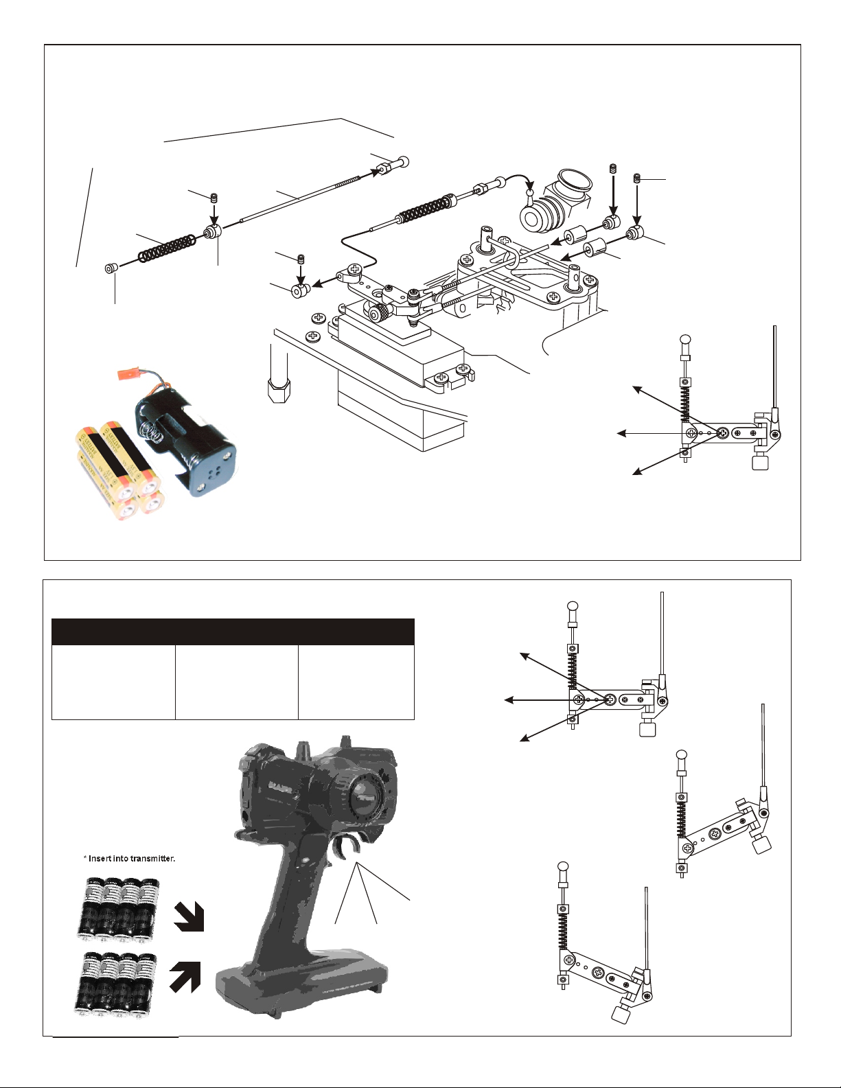
ASSEMBLY OF THE THROTTLE LINKAGE SYSTEM
#30800
Plastic Throttle
kit
Throttle
Spring
Plastic Collar
* Take the plastic collar
from brake system plastic
parts.
3X3mm
Set Screw
#30530
2mm Rod
3X3mm
Set Screw
Plastic Throttle
Ball Joint
* Snap On.
#10300
Alum.Stopper
Note:
Battery life is short when using Alkaline batteries. For safety, we recommend using
Alkaline batteries for only 30 minutes before testing; mostly changing. Battery strength
affects braking power and radio range. If voltage drops while running the car, you will
loose control and destroy your car! This is NOT covered under warranty.
To increase run time, upgrade receiver battery to a 5-cell hump pack. Also, install a
battery fail safe (OFNA # 91002) to further protect your car. But, the most important step
you can make, “is to always use fully charged or fresh batteries when running your car”.
Brake
Idle Position
Full Throttle
3X3mm
Set Screw
#10300
Alum.Stopper
Fuel
Tube
( 6mm )
* Align throttle servo same
as shown.
CHECKING ENGINE THROTTLE
A
1. Insert AA batteries into
transmitter (8 Pcs).
2.Turn on transmitter.
3.Turn on receiver.
4.Center throttle trims as
shown .
IMPORTANT
CHECK RADIO
THROTTLE AND
STEERING SWITCHES
BEFORE RUNNING CAR
* Insert into transmitter.
1. Pull Full Throttle.
B
C
1. Push trigger to full
brake position.
2. Adjust alum. Stopper to
increase or decrease
the brake.
B
A
* Align throttle servo same
as shown.
Brake (C)
A
Idle Position (A)
Full Throttle (B)
• Full throttle arm position.
Spring rod pulls throttle
barrel open and brake
rods release pressure on
brake cams.
Your Radio may be different
than one pictured in this
manual.
C
Radio shown, may be
different from what is in
your kit. OFNA
reserves the right to
change upon stock
availability.
C
B
• Full brake arm position.
Spring compresses
forward and brake rods
pull brake levers.
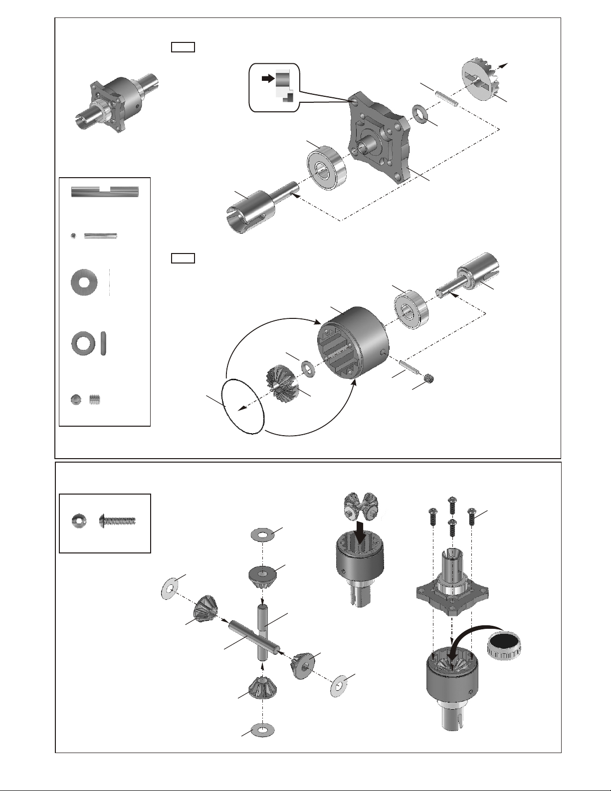
ASSEMBLY OF THE FRONT AND REAR DIFFERENTIAL
Step 1
*Builds two differentials for
font and rear.
*Notice the straight
holes are for the
front and rear only.
30620
7x19x6mm
Ball bearings
30779
2x12.8
30779
P5
O-Ring
30769
Diff. Gear
(Large)
30773
4x27mm
Cross Pin
30779
2x12.8mm
30779
4x10mm Washer
30779
P5 O-Ring
94034
Set Screw
30901
Cap Joint
X2
X2
X4
X2
X2
Step 2
30779
0.5x26mm
O-Ring
30779
P5
O-Ring
30751(Front/Rear)
30761(Center)
Diff. Case
30769
Diff. Gear
(Large)
30620
x19x6mm
Ball bearings
30779
2x12.8
30751(Fro nt/Rear)
30761(Center)
Diff. Case
94034
Set Screw
30901
Cap Joint
ASSEMBLY OF THE DIFFERENTIAL GEAR
94004
3X12mm
Hex Screw
X4
30779
4x10mm
Washer
30769
Diff. Gear
(Small)
30773
4mm
Cross Pin
30769
Diff. Gear
(Small)
30779
4x10mm
Washer
30779
4x10mm
Washer
30769
Diff. Gear
(Small)
30773
4mm
Cross Pin
* Put the differential gears
same as picture shown.
30769
Diff. Gear
(Small)
30779
4x10mm
Washer
94004
3X12mm
Hex Screw
*Apply diff. Gear grease
to the differential, during
assembly.
*Fill the dif. Case to
approx 80% with grease

ASSEMBLY OF THE CENTER DIFFERENTIAL
30773
4x27mm
Cross Pin
Step 1
30911
Break Cap Joint
X2
*Notice the tapered
holes are for the
center differential only.
30620
7x19x6mm
Ball bearings
30779
P5
O-Ring
30769
Diff. Gear
(Large)
30779
2x12.8
30761(center)
30751(F/R)
Diff. Case
30779
2x12.8mm
30779
4x10mm Washer
30779
P5 O-Ring
94034
Set Screw
X2
Step 2
X4
X2
X1
30779
0.5x26mm
O-Ring
ASSEMBLY OF THE DIFFERENTIAL GEAR
94004
3X12mm
Hex Screw
X4
30779
4x10mm
Washer
30779
P5
O-Ring
30779
4x10mm
Washer
30769
Diff. Gear
(Small)
30761(Center)
30751(F/R)
Diff. Case
30769
Diff. Gear
(Large)
* Put the differential gears
same as picture shown.
30620
7x19x6mm
Ball bearings
30779
2x12.8
94034
Set Screw
30911
Break Cap Joint
94004
3X12mm
Hex Screw
30769
Diff. Gear
(Small)
30773
4mm
Cross Pin
30769
Diff. Gear
(Small)
30779
4x10mm
Washer
30773
4mm
Cross Pin
30769
Diff. Gear
(Small)
30779
4x10mm
Washer
*Apply diff. Gear grease
to the differential, during
assembly.
*Fill the dif. Case to
approx 80% with grease
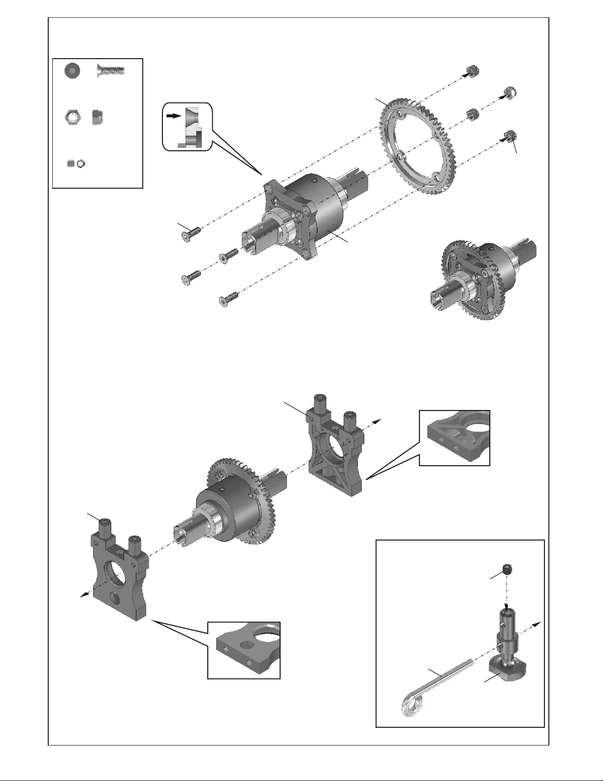
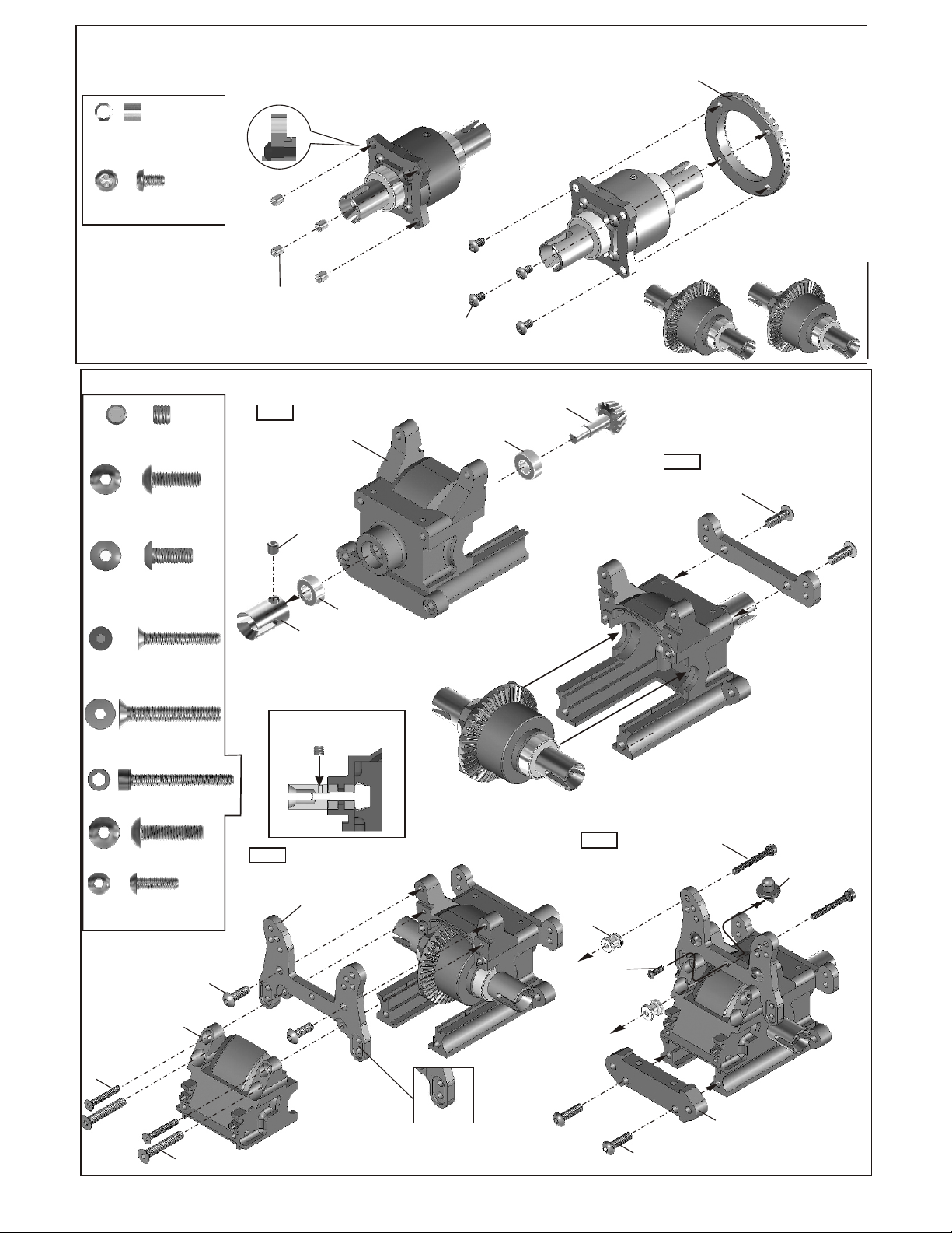
ASSEMBLY OF THE SPUR GEAR
30111
3x10mm
Flat Head Hex Screw
35313
M3 Nylon Nut
94033
M3x3 Set Screw
X4
X4
X4
30111
3x10mm
Flat Head
Hex Screw
*Notice the tapered
holes are for the
center diff. Only.
31040
51T Spur Gear
Center differential
assembly
35313
Nylon Nut
* The picture show are
center differential after
assembly.
30201
Center Diff. Mount
(Front)
Note
the holes for the rear
diff. Mount are width
30201
Center Diff. Mount
(Rear)
* Note:
the holes for the rear
diff. Mount are closer .together
ASSEMBLY OF THE BRAKE CAM
94033
M3x3
Set Screw
30171
Brake Lever
30213
Brake Cam
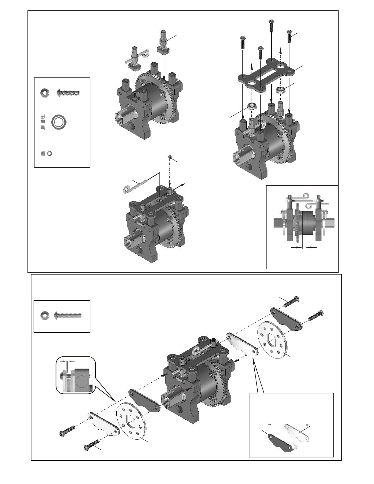
ASSEMBLY OF THE BRAKE CAM AND BRAKE PADS
ASSEMBLY OF THE BRAKE CAM AND CENTER PLATE
30213
Brake Cam
94004
3X12mm
Hex Screw
30652
Center Diff.
Plate
30211
Plastic Bushing
30212
Ball Bearing
94004
3X12mm Hex Screw
30211
5x8x2.5mm
Plastic Bushing
94033
M3x3 Set Screw
X4
X2
X2
30171
Brake Lever
ASSEMBLY OF THE BRAKE PADS
94033
M3x3
Set Screw
30211
Plastic Bushing
30212
Ball Bearing
Note:
94005
3X15mm
Hex Screw
3mm
*Leave 3mm gap
between the brake cam
and nut.
94005
3X15mm Hex Screw
X4
0.5mm
*Leave a 0.5mm space
between brake disk and
brake pad.
94005
3X15mm
Screw
36650
Brake Disk
Steel
36650
Brake Disk
Steel
* Remove the double-side tape
before assembly.
36661
Brake Pad
Linings
36660
Brake Pad
ASSEMBLY OF THE FRONT BEVEL GEARS
*Push 3mm tubes into the
holes of the diff. Case.
30120
Bevel Gear
(Large / Metal)
30121
4x3x3mm
Chromed Tube
3x5mm Hex Screw
X4
X430121
30121
3x4x4mm
Chromed Tube
ASSEMBLY OF THE FRONT GEAR BOX
94036
M5x5 Set Screw
94010
4x12mmHex Screw
Step 1
X1
X2
30010
Gear Box
94036
5x5mm
Set screw
30121
3x5mm
Hex Screw
30630
6x13x5mm
Ball Bearing
30130
Bevel Gear
(Small)
* Builds two differential for
front and rear.
Step 2
94010
4x12mm
Hex Screw
94009
4x10mm
Hex Screw
94022
3x18mm
Flat Head Hex Screw
94029
4x25mm
TP Flat Head
Hex Screw
90018
3X25mm
Cap Screw
94011
4X15mm
Hex Screw
94003
3X10mm
Hex Screw
30010
Gear Box
Front Cover
94022
3x18mm
Flat Head
Hex Screw
X2
X2
X2
X2
X2
X1
94009
4x10mm
Hex Screw
* Place 5x5mm
set screw in d cut.
Step 3
34018
Shock Tower
36730
Cap Joint
30630
6x13x5mm
Ball Bearing
Step 4
36610
Shock Support
Steel
36507
Shock Support
Alum
94003
3X10mm
Hex Screw
90018
3X25mm
Cap Screw
34021
Front Upper Arm
Holder
30102
Front body
Post
94029
4x25mm
Flat Head Hex Screw
* Notice the direction.
94011
4X15mm
Hex Screw
30160
Front Lower
Arm Holder
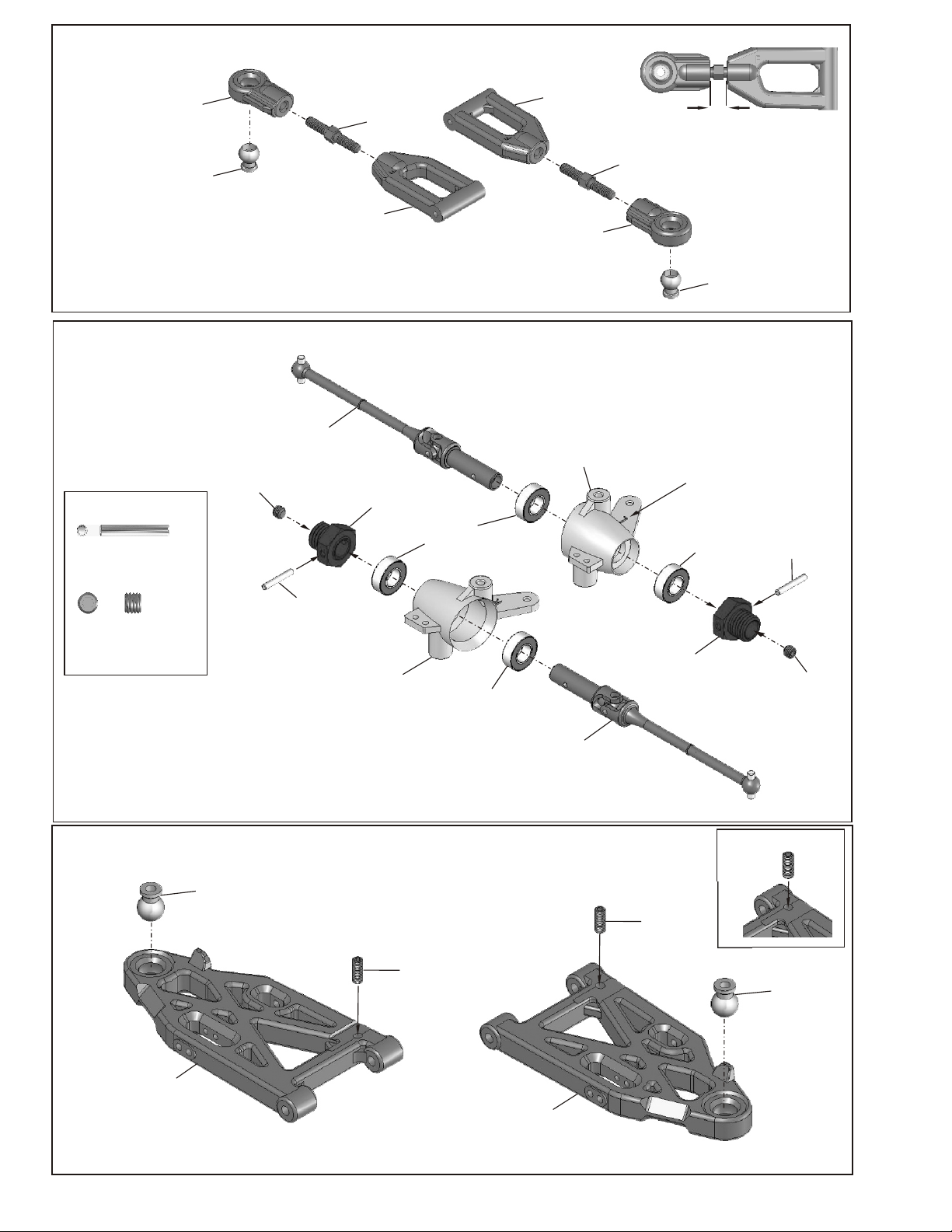
ASSEMBLY OF THE FRONT UPPER ARMS
* Builds two upper arms for use.
34034
Front Upper
Arm Ball End
40104
10mm
Ball and Socket
11
ASSEMBLY OF THE KNUCKLE ARMS
36152
Universal Joint
90026
5x5mm
Set Screw
34034
Front Upper
Arm (Right)
36860
5x35mm
36054
Wheel Hub
34034
Front Upper
Arm (Left)
34034
Front Upper
Arm Ball End
40103
Knuckle Arm
(Left)
36860
5x35mm
*"L" mark for left side.
* Leave 8mm
40104
10mm
Ball and Socket
36055
2.5x16.8mm Pin
90026
5x5mm Set Screw
X2
36055
2.5x16.8mm
X2
Pin
ASSEMBLY OF THE FRONT LOWER ARMS
40104
10mm
Steering Ball
40103
Knuckle Arm
(Right)
36870
4x10mm
Set Screw
36053
8x16x5mm
Ball bearings
36053
8x16x5mm
Ball bearings
36152
Universal Joint
36054
Wheel Hub
36870
4x10mm
Set Screw
36053
8x16x5mm
Ball bearings
* A4x10mm set screw is used
to adjust the ride heigh.
36055
2.5x16.8mm
Pin
90026
5x5mm
Set Screw
40104
10mm
Steering Ball
34035
Front Lower
Arm
34036
Front Lower
Arm
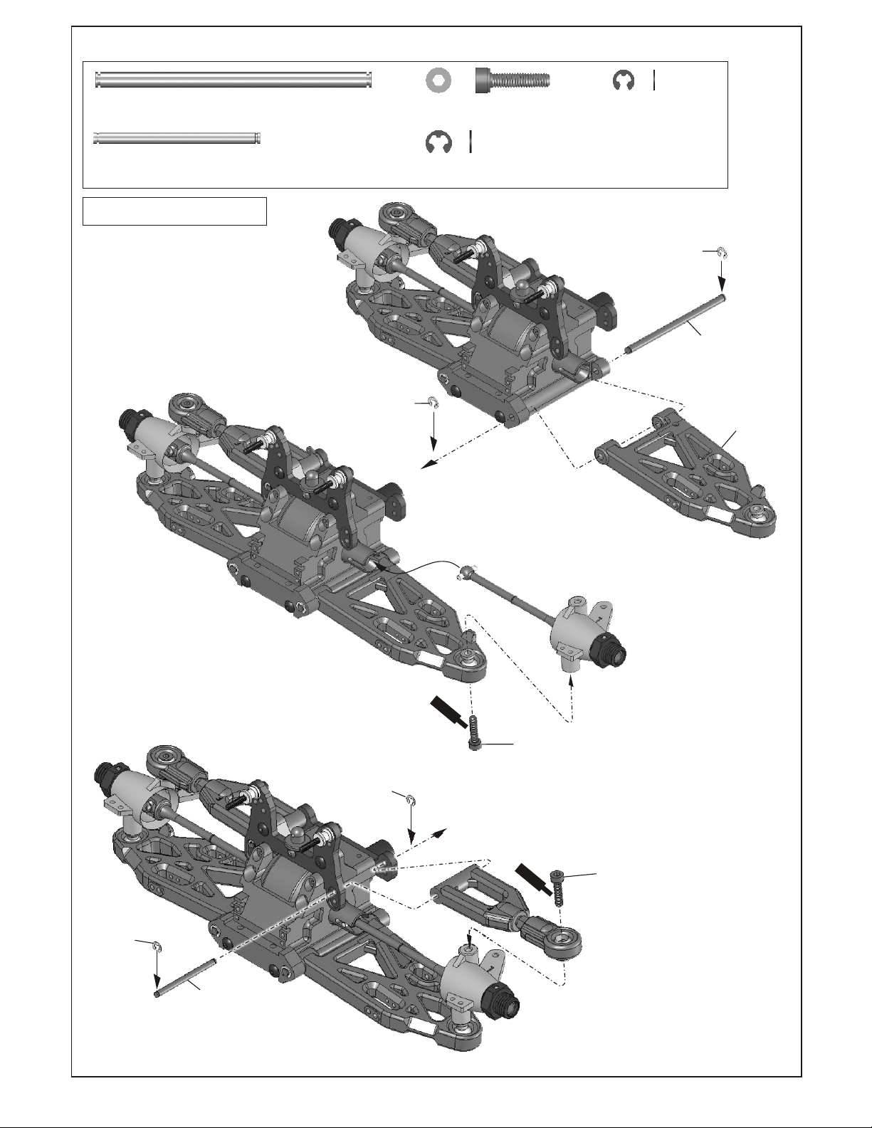
ASSEMBLY OF THE FRONT ARMS
30151
4mm Arm Shaft
30152
3mm Arm Shaft
Assembly of the right and left hand side
are the same.
X2
X2
3mm
E-Ring
40104
4x16mm Cap Screw
90021
3mm E-Ring
90020
X4
2.5mm E-Ring
X4
X4
90021
3mm
E-Ring
30151
4mm
Arm Shaft
34035
Front Lower
Arm
90020
2.5mm
E-Ring
30152
3mm Upper
Arm Shaft
90020
2.5mm
E-Ring
S
cre
C
e
w
m
ent
40104
4x16mm
Cap Screwl
Scre
Cem
w
en
t
40104
4x16mm
Cap Screwl
CLIP IN THE CASTER ADJUSTER
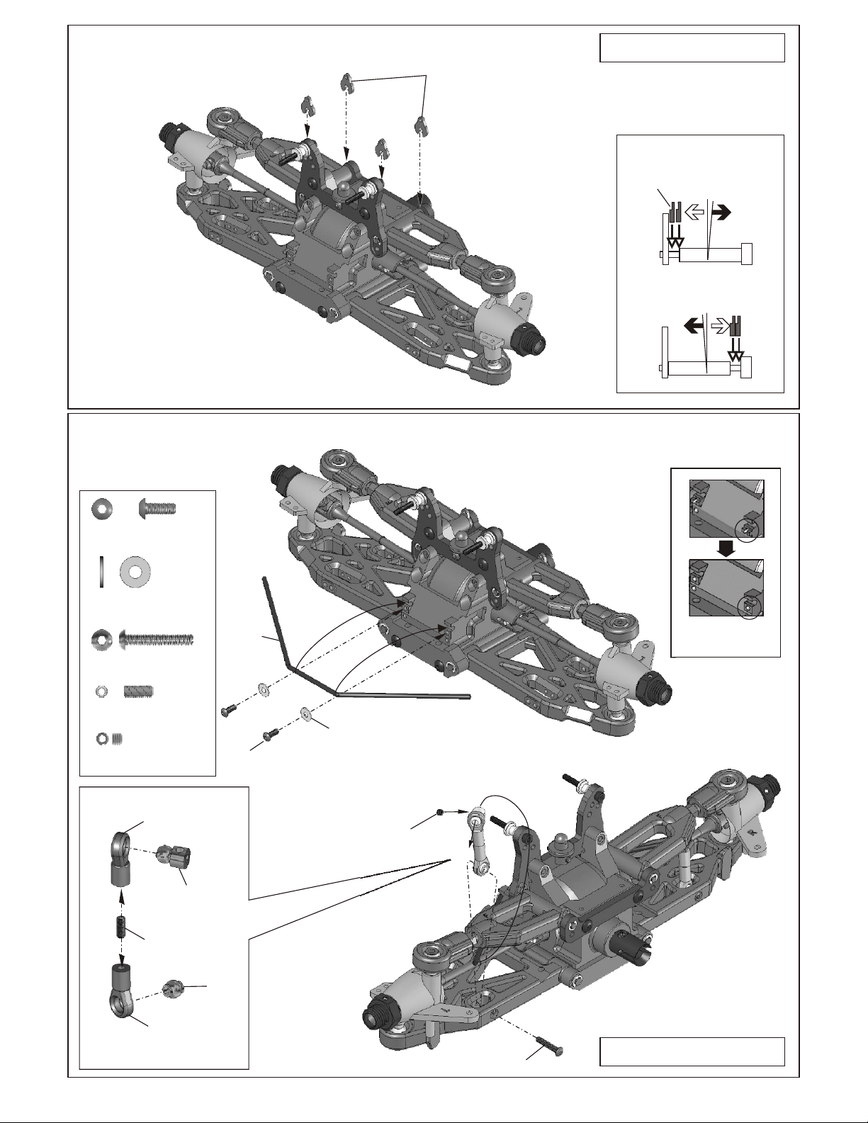
ASSEMBLY OF THE FRONT STABILIZER
34037
Caster Adjuster
Assembly of the right and left hand side
are the same.
* o change the caster angle .use adjuster t
*Caster angle will
Caster
become bigger.
Adjuster
*Caster angle will
become less.
94002
3x8mm button Screw
3x8x0.8mm
Washer
94006
3x18mm Screw
34035
M3x8mm Set Screw
94033
M3x3 Set Screw
40029
Stabilizer
Ball End
34035
M3x8mm
Set Screw
X2
X2
X2
X2
X2
30341
Stabilizer Ball
34027
Stabilizer
94002
3x8mm
Screw
3x8x0.8mm
Washer
94033
M3x3
Set Screw
A
B
* Cut the plastic as shown.
40029
Stabilizer
Ball End
30403
6mm Ball
94006
3x18mm
Screw
Assembly of the right and left hand side
are the same.
 Loading...