

OFNA Racing Titan Twin User Manual
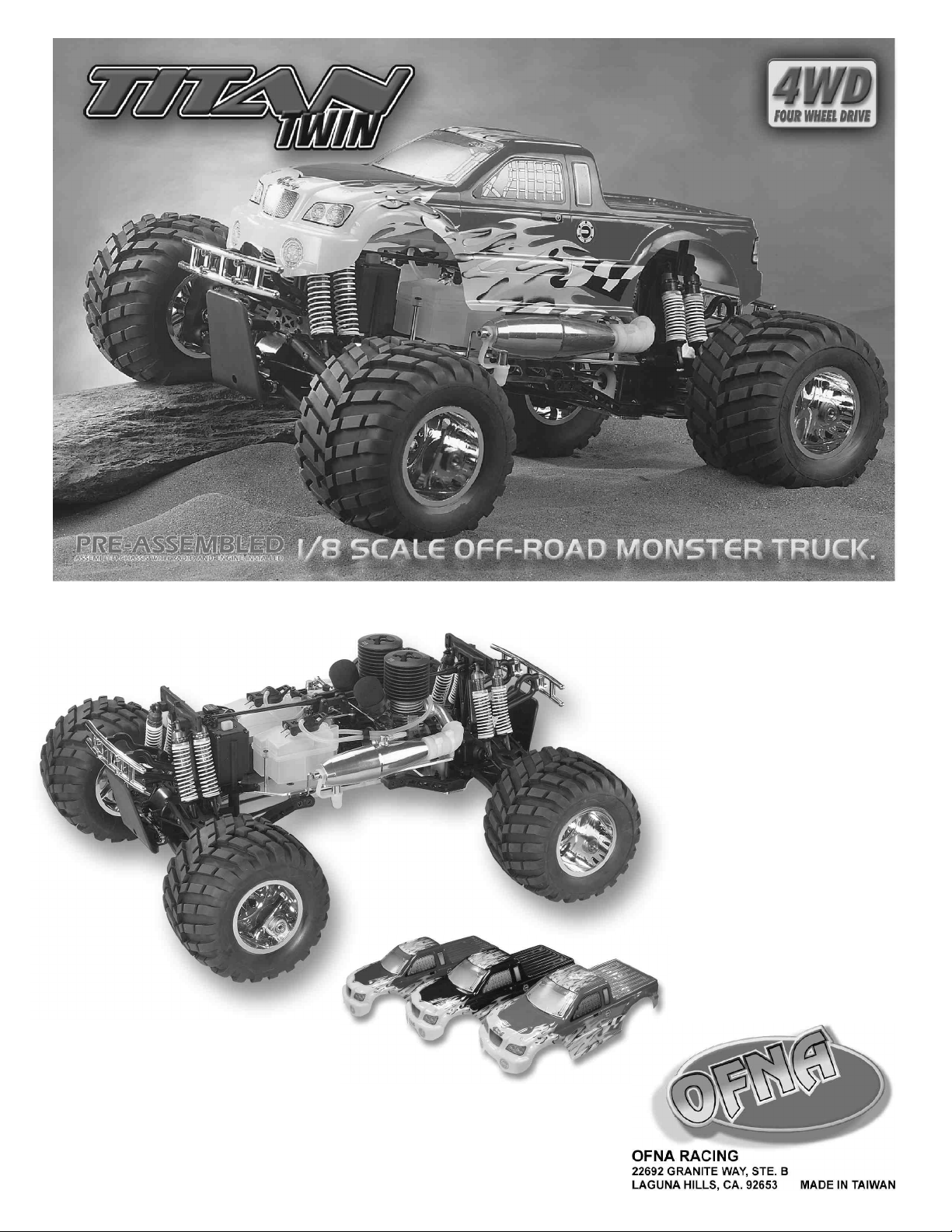
INSTRUCTION MANUAL
PLEASE READ INSTRUCTIONS CAREFULLY BEFORE ASSEMBLING
THIS MODEL.
KEEP THIS MANUAL FOR PARTS NUMBERS WHEN ORDERING.

REQUIRED FOR OPERATION
THINGS NEEDED
Glow Fuel
20%
AA Batteries ( 12 pcs )
You will need to buy a few items to start the engine and run the car.
• Use 20% nitro CAR fuel. Do not use airplane or heli fuels, they will
over heat engine.
• Buy LONG glow plugs, like OFNA/PICCO Plug (#51007 or 51008).
Use plugs without idle bar. Do NOT use plugs, like the MC-59 or OS-8
In your box you will find..
• #10162 - Bottle, 250cc
• #10219 - Red “D” size glow heater
You need to get batteries for the radio transmitter and the car
receiver packs.
• Radio TX needs (8) eight AA batteries.
• Car/Truck needs (4) four AA Ni-cad batteries 2000Mah OFNA
#10196 or Alkaline type batteries will work, but braking will be
reduced to a 30 minute life. The best is to use a 5 cell hump pack for
increased voltage..
10214
Over-nite
Charger
#10212 NiHm Hump Pack,
see charger 10214.
Recommended Option:
You may want to upgrade the car battery pack to a Ni-Cad or NiHm 5
cell type(600AE). This will give more run time. OFNA #10212
1200NiMh Hump Pack and NiHm Battery Charger #10214
TOOLS NOT INCLUDED IN KIT
Phillips Type Screw Drivers ( L )
Phillips Type Screw Drivers ( S )
Needle Nose Pliers
Knife
Cutter
Curved Scissors
Precision Caliper
Super Glue
Cross Wrench
#17109 $3.95
Wheel Nut
Wrench
INCLUDED WITH KIT
Shock Oil
Grease Box
7mm and 5.5mm
Hex Wrench
5mm
Hex Wrench
3mm
Hex Wrench
2.5mm
Hex Wrench
1.5mm
Hex Wrench

MUST READ THIS BEFORE RUNNING
Running a nitro kit is fun and easy, but to make this a safe rusting.
and good experience you must observe a few rules. This
kit is extremely fast, easily over 40MPH, and can seriously
injure someone if you are not careful.
Where to run car?
• Any running area you choose must be dry. Do not run
car near any water or wet dirt.
• Do not run on public streets. It is very easy to have the
car run over or damaged by hitting the curb.
• Do not operate car in tight confined places. The car is
very fast and will easily hit something.
• Do not run near people or animals.
and will too easily hit someone.
• Due noise, you will want to consider the surrounding
area when operating the car.
• Do not operate the car at night. You will not be able to
drive it without hitting something.
• Do not operate the car indoors. Engine exhaust is not
healthy.
Glow Fuel
• Glow fuel is poisonous!
• Glow fuel is flammable!
• Do not leave in fuel bottle with lid off at any time. label for additional precautions.
• Do not use any fuel other than glow fuel in this engine.
First Time Starting the Engine
Caution! When starting engine make sure the following is
observed. • Always turn off the car BEFORE turning off radio.
• Set engine Master needle to 3 turns (rich setting)
• Do not do this alone, get an experienced friend to help at • DAMAGE DUE CAR RUN AWAY IS NOT A WARRANTY
first. ISSUE.
• Fill fuel tank, try not to spill fuel. Do not spill fuel on
receiver
• Hold car off the ground, so it will not runaway when first
starts
• Turn on Radio and check the linkage before starting
engine.
• Turn on car receiver battery switch.
• Always have an air filter on the carburetor to keep dirt
out.
Engine Break-in
• See Engine Page.
The car is very fast
• Clean oil and dirt from chassis with a degreaser.
Precautions
• This kit is not a toy. Always run car with a second
person as a spotter and pitman.
• Hot Parts - The pipe, manifold, engine and head are very
hot and will cause burns.
• Rotating Parts - Keep hands away from the drive train,
wheels, and engine when engine is running.
• Radio - Check batteries life before running the car. If
radio does not have full control of the car with steering
and/or throttle/brake do not run until corrected. Failure to
correct this will result in possible injury and damage to the
car or property.
• Glow fuel - Do leave the glow fuel unattended with the lid
off. Fuel contains Methanol and Nitro Methane and is
flammable and poisonous.
Store fuel in cool ventilated location. Refer the glow fuel
• Car Fuel tank - Never store fuel in car tank, it will ruin the
engine if left in tank.
IF YOU DO NOT BREAK-IN ENGINE
CORRECTLY, MAINLY AT LOW RPM,
YOU WILL BREAK THE CONNECTING
ROD!
FAILURE TO NOT READ AND
FOLLOW BREAK-IN ENGINE
Emergency Stopping Engine When Running
• Remove air filter and cover carb. intake.
• Squeeze fuel line and hold until engine stops.
• With a rag, cover exhaust outlet.
Storing Car After Running
• Remove fuel from tank and fuel lines
• Turn off radio in car
• Put a few drops of after run in engine to keep it from
INSTRUCTIONS WILL VOID
WARRANTY!
CHECK RADIO SETTING AND
LINKAGE BEFORE STARTING
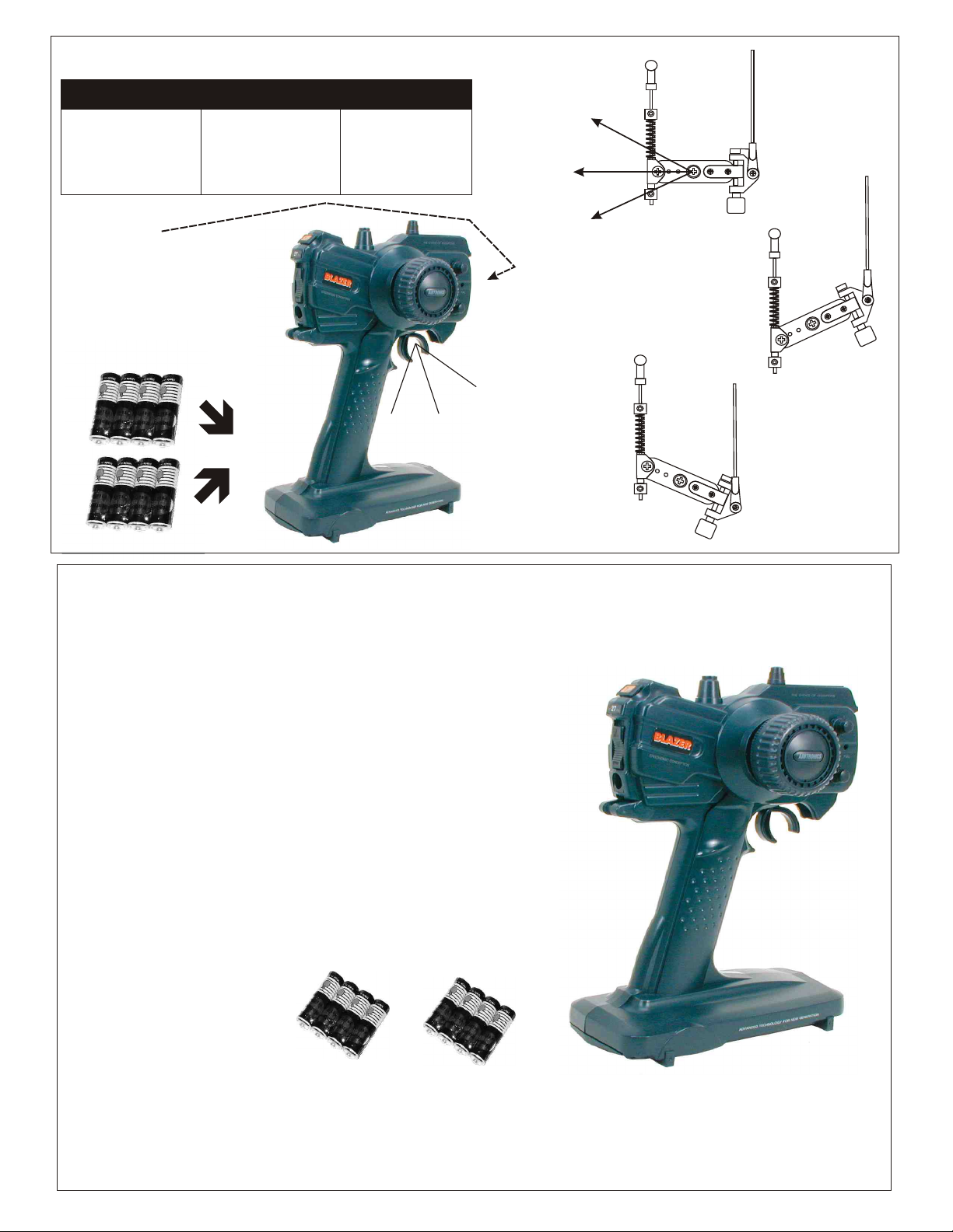
CHECKING ENGINE THROTTLE
A
1. Insert AA batteries into
transmitter (8 Pcs).
2.Turn on transmitter.
3.Turn on receiver.
4.Center throttle trims as
shown .
1. Pull Full Throttle.
B
C
1. Push trigger to full
brake position.
2. Adjust alum. Stopper to
increase or decrease
the brake.
* Align throttle servo same
as shown.
Brake (C)
A
Idle Position (A)
IMPORTANT
CHECK RADIO THROTTLE
AND STEERING SWITCHES
BEFORE RUNNING CAR
* Insert into transmitter.
C
B
A
Note:
Battery life is short when using Alkaline batteries. For safety, we
recommend checking Alkaline batteries after 30 minutes. Battery
strength affects radio range; in the case of a monster truck, it affects
brake power. If voltage drops while running the car, you will loose
control and destroy your car! This is NOT covered under warranty.
Full Throttle (B)
• Full throttle arm position.
Spring rod pulls throttle
barrel open and brake
rods release pressure on
brake cams.
B
C
• Full brake arm position.
Spring compresses
forward and brake rods
pull brake levers.
To increase run time, upgrade receiver batteries to AA Ni-Cad or
NiMH type. But, the most important step you can make, “is to
always use fully charged or fresh batteries when running your car”.
The beat performance is achieved by changing to a 6 volt 5 cell
hump pack, OFNA #10212. The servo have their greatest power at
6 volts.
Insert 8 pcs AA batteries into transmitter.
Radio shown may vary depending on
availability. Therefore radio pictured on
box may or may not be the same.
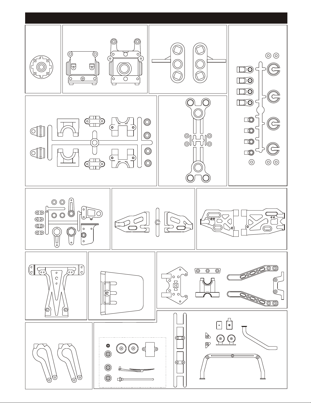
PLASTIC PARTS
40003
Diff. Case
40040
Center Diff Mount Tree
40017
Front and Rear Gear Boxes
36901
Front Knuckles, Pivot Ball
31304
Rear Hub,
Pivot Ball
40056
Plastic Shock Parts Tree
40031
Servo Saver Plastic Tree
40203
Shock Tower part
40207
Bumper Mounts
40272
Front and Rear Upper Arms
Super
40204
Chassis Skip Plate
40206
Chrome Roll Bar
Plastic Parts(w/spot light)
40273
Front Lower Arms.
40271
Rear Lower Arms.
40205
Arm Holder/Center Diff. Mount /Side Chassis Brace
Plastic Parts
Super

ASSEMBLY OF THE DIFFERENTIAL
( Builds two differentials for front and rear.)
40006
Cap Joint
30701
4x4mm
Set Screw
40010
2.5x13.8mm
Pin
*Put the O-ring
in inside of the diff. case
and press it flush against
the bottom.
40009
P6
O-Ring
40012
6x15mm
Washer
40010
2.5x13.8mm
Pin
40009
P6
O-Ring
36053
8x16mm
Bearing
40006
Cap Joint
36053
8x16mm
Bearing
Note: Diff must always use
gear shim. If no shims are used,
we have found that diff may break.
30779
4 x 10mm
washer
Option:
49001 - Gears, HD Steel
40003
Diff. Case
30773
4mm
Cross pin
40004
30779
4 x 10mm
washer
30773
4mm
Cross pin
Diff.Gear
(Large)
40004
Diff. Gear
(Small)
40004
Diff. Gear
(Small)
Note:
- Add grease into diff case before closing.
30779
4 x 10mm
washer
40004
Diff.Gear
(Large)
40012
6x15mm
Washer
40214
Large
Bevel Gear
40011
Diff. Gasket
40214
Large
Bevel Gear
3x12mm
Flat Head
Tapping Screw
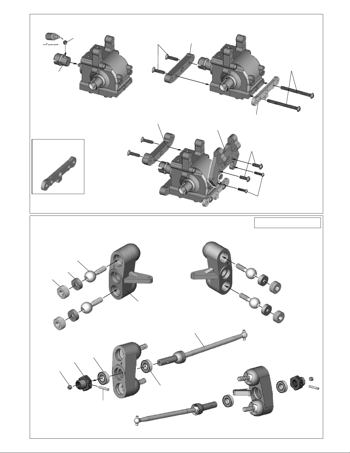
ASSEMBLY OF THE GEAR BOX
( Builds two gear box for front and rear.)
36053
8x16mm
Bearing
49012
40017
Gear Box
13T
Bevel Gear
(l)Smal
36053
8x16mm
Bearing
No need to add shims to
this side. Loosening gear
mesh will only cause gear
to skip.
Note: ALWAYS USE OR ADD MORE!
Adjust gear mesh by using #40024 shims. Add
shim to either side for mesh. Recommend a
tight feel but not binding or loose.
40024
13x16x0.2mm
Shim
40017
Gear Box
ASSEMBLY OF THE FRONT ARMS HOLDER
* Make two gear boxs for front and rear
5x4mm
Set Screw
Screw Cement
Screw Cement
MW-02
Cap Joint
4x16mm
Flat Head
Hex Screw
J-11
Front Lower Arm
Holder (Rear/Plastic)
4X45MM
Hex Screw
( Small Head)
OPT:JS-02
OPT:JS-02
CNC 7075
CNC 7075
Front Lower Arm
Front Lower Arm
Holder
Holder
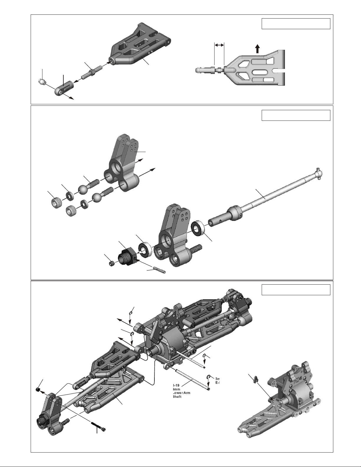
ASSEMBLY OF THE FRONT KNUCKLE ARMS
( Left-Side ) ( Right- Side )
GS-05
14mm
Steering Ball
G-07
Plastic Washer
GS-06
14mm
Alum. Nut
J-11
Front Upper Arm
Holder ( Rear/ Plastic)
M-06
Upper Arm
Holder
J-18
Front Lower Arm
Holder (Front/Alum.)
4X12mm
Hex Screw
( Small Head)
3x12mm
Hex Screw
Assembly of the right and left hand side
are the same.
5x4mm
Set Screw
#267C-O
8mm
Alum.
Wheel Hub
#267D
8x16mm
Ballbearing
#267E
2.5x17mm
Pin
GS-03
Ball type
Knuckle Arms
#267D
8x16mm
Ballbearing
MP-03
Front/Rear CVD

ASSEMBLY OF THE SUSPENSION ARMS
MP-01A
Front Upper
Arm
MP-01B
Rear Lower Arm
MP-07
3x64.4mm
Shaft
ASSEMBLY OF THE FRONT BILIZER
M3x10mm
Hex Screw
MP-06
Stabilizer
ASSEMBLY OF THE SERVO SAVER AND
STEERING ROD
4x8mm
Plastic Bushing
J-31
Alum.
Servo Saver
Tube
J-27
Servo Saver
Plastic Bushing
J-27
Servo Saver
Horn Plastic
J-27
Servo Saver
Horn Plastic
J-13A
Stabilizer Holder
J-33
Steering Plate
Hex Screw
J-28
Servo Saver
Connecting Plate
3x3
Set Screw
Put the stabilizer rod
into lower arm as shown.
* Take the 4x8mm Plastic Flange bushing
and Plastic Bushing from servo saver plastic
parts tree
G-25
Steering
Ball End
3x20mm
Screw
3x3
Set Screw
J-25
Stabilizer
Ball End
M3x8mm
Set Screw
#154
Stabilizer
Ball End(Long)
* Make two steering rods for left
and right hand side.
MP-05
4x76mm
turnbuckle
A-34B
StabilizerBall
A-40A
6mm
Ball
G-25
Steering
Ball End
J-29
Servo Saver
Spring
J-30
Servo Saver
Adjuster
J-27
Servo Saver
Plastic Bushing
76mm
0 10 20 30 40 50 60 70 80
1:1
mm
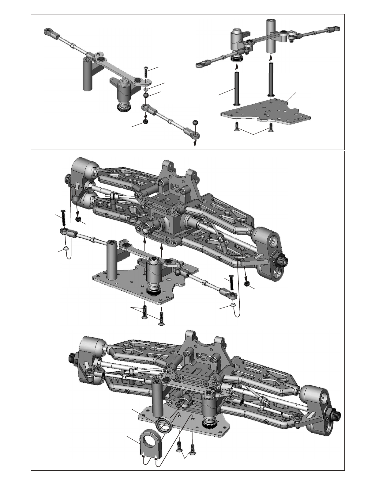
ASSEMBLY OF THE SERVO SAVER ONTO LOWER CHASSIS
3X16mm
Hex Screw
J-35
Alum.
Taper Washer
G-25
7mm Ball
3mm
Nylon Nut
M-34
Servo Saver
Post
4x12mm
Flate Head
Hex Screw
M-30
Lower Chassis
3x18mm
Flat Head
Hex Screw
J-35
Alum.
Taper Washer
M3
Nylon Nut
4x16mm
Flat Head
Hex Screw
3x18mm
Flat Head
Hex Screw
J-35
Alum.
Taper Washer
M3
Nylon Nut
MW-05
15x21x4mm
Ballbearing
MW-03
Cap Joint
Support Mount
4x12mm
Flat Head
Hex Screw
ASSEMBLY OF THE REAR UPPER ARMS
*Builds two arms for left and right hand side.
Assembly of the left and right hand side
are the same.
G-26
5x35mm
Tunebuckle
G-25
7mm Ball
ASSEMBLY OF THE REAR WHEEL HUB
*Builds two hubs for left and right hand side.
# 306E
12mm
Alum.
Hex Screw
G-09
7mm
Plastic
Ball End
#306D
Plastic Washer
#306F
11mm
Ball & Screw
MP-01B
Rear Upper
Arm
#306C
Rear Hub
( Ball Type )
* Leave 12.5mm.
*Note: This direction to front.
Assembly of the right and lefthand side
are the same.
MP-03
Font/Rear
CVD Shaft
#267C-O
Wheel Hub
5x5mm
Set Screw
ASSEMBLY OF THE REAR HUB
AND SUSPENSION ARMS
INTO GEAR BOX
*Insert the rear drive shaft
into cap joint before assembly
the rear lower arm.
M3
Nylon Nut
3mm
E-Ring
#267D
8x16mm
Ballbearing
#267E
2.5x16.8mm
Pin
2.5mm
E-Ring
J-19
4mm
Lower Arm
Shaft
#267D
8x16mm
Ballbearing
MP-07
3x64.4mm
Shaft
2.5mm
E-Ring
3mm
E-Ring
Assembly of the right and lefthand side
are the same.
*Put the plastic clips
into lower arm shaft.
#306
Plastic Clips
3x25
Hex Screw
MP-02
Rear
Lower Arm
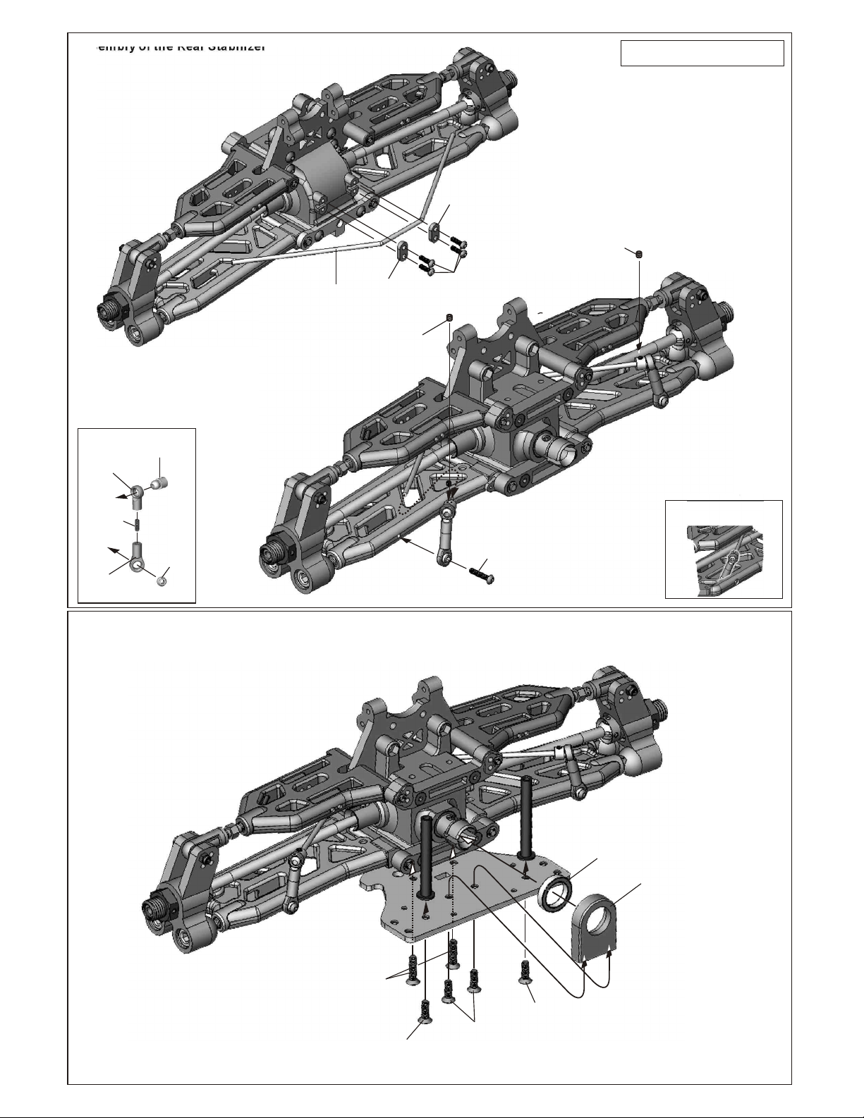
Assembly of the Rear Stabilizer
J-13A
Stabilizer
Holder
Assembly of the left and right hand side
are the same.
3x3
Set Screw
MP-06
Stabilizer
J-25
Stabilizer
Ball End
M3x8mm
Set Screw
#154
Stabilizer
Ball End(Long)
A-34B
StabilizerBall
A-41
6mm
Ball
ASSEMBLY OF THE CAP JOINT SUPPORT MOUNT
AND POST
J-13A
Stabilizer
Holder
3x3
Set Screw
3x10mm
Hex Screw
3x20mm
Screw
Put the stabilizer rod
into lower arm as shown.
4X16mm
Flat Head
Hex Screw
4X12mm
Flat Head
Hex Screw
4X12mm
Flat Head
Hex Screw
4X12mm
Flat Head
Hex Screw
MW-05
15x21x4mm
Ballbearing
MW-03
Cap Joint
Support Mount
 Loading...