

OFNA Racing Ravager User Manual

MUST READ THIS BEFORE RUNNING
Running a nitro kit is fun and easy, but to make this a safe • Clean oil and dirt from chassis with a degreaser.
and good experience you must observe a few rules. This
kit is extremely fast, easily over 40MPH, and can seriously
injure someone if you are not careful.
Where to run car?
• Any running area you choose must be dry. Do not run
car near any water or wet dirt.
• Do not run on public streets. It is very easy to have the
car run over or damaged by hitting the curb.
• Do not operate car in tight confined places. The car is
very fast and will easily hit something.
• Do not run near people or animals.
and will too easily hit someone.
• Due noise, you will want to consider the surrounding
area when operating the car.
• Do not operate the car at night. You will not be able to
drive it without hitting something.
• Do not operate the car indoors. Engine exhaust is not
healthy.
Glow Fuel
• Glow fuel is poisonous!
• Glow fuel is flammable! label for additional precautions.
• Do not leave in fuel bottle with lid off at any time.
• Do not use any fuel other than glow fuel in this engine. • Car Fuel tank - Never store fuel in car tank, it will ruin the
First Time Starting the Engine
Caution! When starting engine make sure the following is
observed.
• Set engine Master needle to 3 turns (rich setting) • DAMAGE DUE CAR RUN AWAY IS NOT A WARRANTY
• Do not do this alone, get an experienced friend to help at
first.
• Fill fuel tank, try not to spill fuel. Do not spill fuel on
receiver
• Hold car off the ground, so it will not runaway when first
starts
• Turn on Radio and check the linkage before starting
engine.
• Turn on car receiver battery switch.
• Always have an air filter on the carburetor to keep dirt
out.
The car is very fast
Precautions
• This kit is not a toy. Always run car with a second
person as a spotter and pitman.
• Hot Parts - The pipe, manifold, engine and head are very
hot and will cause burns.
• Rotating Parts - Keep hands away from the drive train,
wheels, and engine when engine is running.
• Radio - Check batteries life before running the car. If
radio does not have full control of the car with steering
and/or throttle/brake do not run until corrected. Failure to
correct this will result in possible injury and damage to the
car or property.
• Glow fuel - Do leave the glow fuel unattended with the lid
off. Fuel contains Methanol and Nitro Methane and is
flammable and poisonous.
Store fuel in cool ventilated location. Refer the glow fuel
engine if left in tank.
• Always turn off the car BEFORE turning off radio.
ISSUE.
IF YOU DO NOT BREAK-IN ENGINE
CORRECTLY, MAINLY AT LOW RPM,
YOU WILL BREAK THE CONNECTING
ROD!
FAILURE TO NOT READ AND
Engine Break-in
• See Engine Page.
Emergency Stopping Engine When Running
• Remove air filter and cover carb. intake.
• Squeeze fuel line and hold until engine stops.
• With a rag, cover exhaust outlet.
Storing Car After Running
• Remove fuel from tank and fuel lines
• Turn off radio in car
• Put a few drops of after run in engine to keep it from
rusting.
FOLLOW BREAK-IN ENGINE
INSTRUCTIONS WILL VOID
WARRANTY!

FORCE PULL START ENGINES
Thank you for purchasing an OFNA engine. We appreciate your choice and know you will enjoy running it. Please
note that the Force information in engine box is subject to change with out notice.
Carburetor Low end and barrel stop screws are pre-set by factory.... Do not change until break-in is done.
NEW ENGINE BREAK-IN
Your OFNA engine is extremely tight when the piston is at the top of the stroke and turning the crankshaft by hand.
This is normal for a new ABC type engine. The piston and sleeve are matched for fit and the top of the sleeve is
tapered for a tight fit. As you run your engine, this tightness should diminish. There is no cause for alarm, because
as the engine warms up, the brass sleeve will expand faster than the aluminum piston and the engine will turn freer.
As with any new engine, there are many high spots and tight fits in the matching process. High spots create hot
spots that must be broke-in. Therefore, the break-in process is very important to provide good service by the OFNA
engine. So, you must run the engine rich (COOL) for the first three tanks of fuel. We recommend using one gallon
of 20% BLUE THUNDER 0R BYRON’S 2000 as break-in fuel. Other break-in type fuels or added oil is NOT
needed. DO NOT OVER REV THE ENGINE WHEN FIRST STARTING, this could break the piston and over heat
sleeve. Let engine run at low RPM for one tank to break-in connecting rod bearing before starting full break-in.
Break-in the engine in the car, by running the engine at a rich setting. Run the car from a slow to fast speed with
short bursts of speed. You need to buildup a little heat in the engine, but not too hot. In a rich setting, the engine
will run cold. In the leaner setting the engine run hot, this is not good yet. Do not heat up the engine too much at
this time. After about one (1) tank, turn the Master Needle Valve, clock wise, 1/8 of a turn leaner or clockwise.
Keeping the fuel tank full, continue the process until you slowly turn the Master Needle Valve, 1/8 of turn each time,
too a leaner point and in which the engine runs at high RPM and power, but still keep max temp. of 250 deg. F. At
this point you must stop, too lean of a setting will heat up engine and damage the piston. A normal operating
temperature is around 220 to 270 Deg. Temperatures of 300 Deg. and above will damage engine and shorten life.
NEEDLE SETTINGS
Master Needle Valve - main control for fuel mixture. Set at 3 to 31/2 turns from closed. Adjust this needle for
maximum RPM and power without being too lean or too hot. Make sure you start at bottom of needle seat!!
Side Carburetor Needle (Low Speed) - This needle is in the center side of the carburetor and provide throttle
response. It is not the idle adjustment. Set FLUSH with the brass sleeve. Turning in is Lean and Out is Rich. Do
not adjust this needle until the Master Needle is set for power and top speed. This will only effect throttle response.
FOR THREE NEEDLE CARBURETORS, DO NOT ADJUST MID RANGE NEEDLE, PRESET BY FACTORY
Barrel Stop Screws - Used for adjusting Idle. Set for 1/16th inch gap to start new engines. You can open more for
faster idle.
USE LONG GLOW PLUG WITHOUT IDLE BAR,
OFNA/PICCO #51007 & 51008 IS RECOMMENDED
OFNA RACING , 7 VANDERBILT, IRVINE, CA. 92618 • TEL:(949)586-2910

RTR KITS - REQUIRED FOR OPERATION
THINGS NEEDED
Glow Fuel
20%
AA Batteries ( 12 pcs )
You will need to buy a few items to start the engine and run the car.
• Use 20% nitro CAR fuel. Do not use airplane or heli fuels, they will
over heat engine.
• Buy LONG glow plugs, like OFNA/PICCO Plug (#51007 or 51008).
Use plugs without idle bar. Do NOT use plugs, like the MC-59 or OS-8
In your box you will find..
• #10162- Bottle, 250cc
• #10219 - Red “D” size glow heater
10195
7.2 Volt
Over-nite
Charger
You need to get batteries for the radio transmitter and the car receiver packs.
• Radio TX needs (8) eight AA batteries.
• Shaft Starter requires a 7.2Volt battery pack and charger OFNA #10195
• Car needs (4) four AA Ni-cad batteries 2000Mah or higher or (4) Alkaline., Alkaline type
batteries will work, but braking will be reduced and 30 minute life. The best for car, is to use a 5
cell hump receiver pack for increased voltage and longer life..
10214
Rec’v Bat.
Over-nite
Charger
#10212 Rec’v Bat.
NiHm Hump Pack,
see charger 10214.
Recommended Option:
You may want to upgrade the car battery pack to a Ni-Cad or NiHm 5 cell type(600AE). This will
give more run time. OFNA #10212 1400NiMh Hump Pack and NiHm Battery Charger #10214
TOOLS NOT INCLUDED IN KIT
Cross Wrench
#17109 $3.95
Phillips Type Screw Drivers ( L )
Phillips Type Screw Drivers ( S )
Glow Plug & 17MM Cross Wrench
#10801 $6.95
Instant Cemment
Cutter
Curved Scissors
Masking Tape
Precision Caliper
Needle Nose Pliers
Knife
Brush
Paints
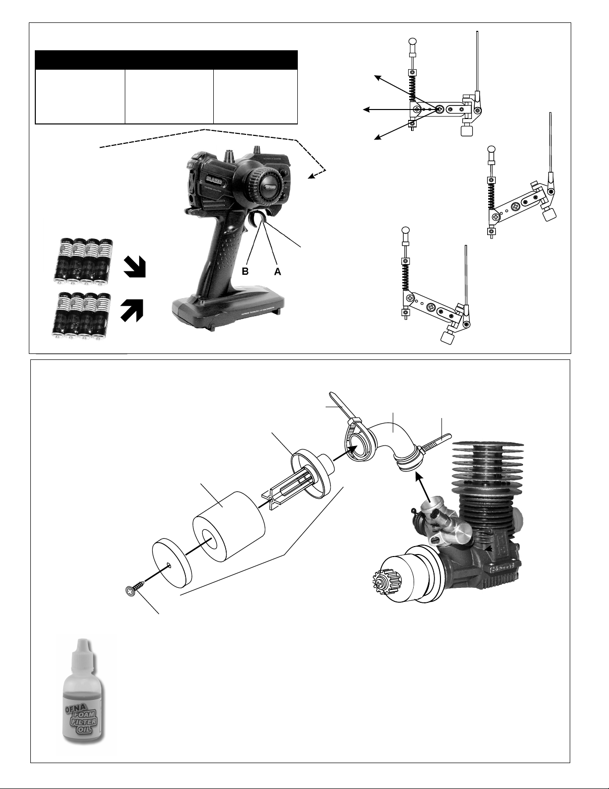
CHECKING ENGINE THROTTLE
* Align throttle servo same
as shown.
A
1. Insert AA batteries into
transmitter (8 Pcs).
2.Turn on transmitter.
3.Turn on receiver.
4.Center throttle trims as
shown .
IMPORTANT
CHECK RADIO THROTTLE
AND STEERING SWITCHES
BEFORE RUNNING CAR
* Insert into transmitter.
1. Pull Full Throttle.
B
1. Push trigger to full
brake position.
2. Adjust alum. Stopper to
increase or decrease
the brake.
C
Brake ©
A
Idle Position (A)
Full Throttle (B)
• Full throttle arm position.
Spring rod pulls throttle
barrel open and brake
rods release pressure on
brake cams.
B
C
B
A
C
• Full brake arm position.
Spring compresses
forward and brake rods
pull brake levers.
ASSEMBLY OF THE AIR FILTER
#10016
Air Filter
Sponge
Refills
94003
3 x 10mm
Tapping Screw
#10021 - Black
#10027 - Yellow
#10028 - Pink
Nylon Strap
( Small )
#10029 - Blue
Air Filter Connector
Nylon Strap
( Small )
#10017 - Blue
#10018 - Yellow
#10019 - Rose
Foam Air filters Unit
You must oil foam filter before use.
#10015, Foam
Filter oil, Very
Sticky....$9.95
Filter will not work if not oiled.
Clean with soap and water only.
You will damage foam if washed
if fuel!
40017
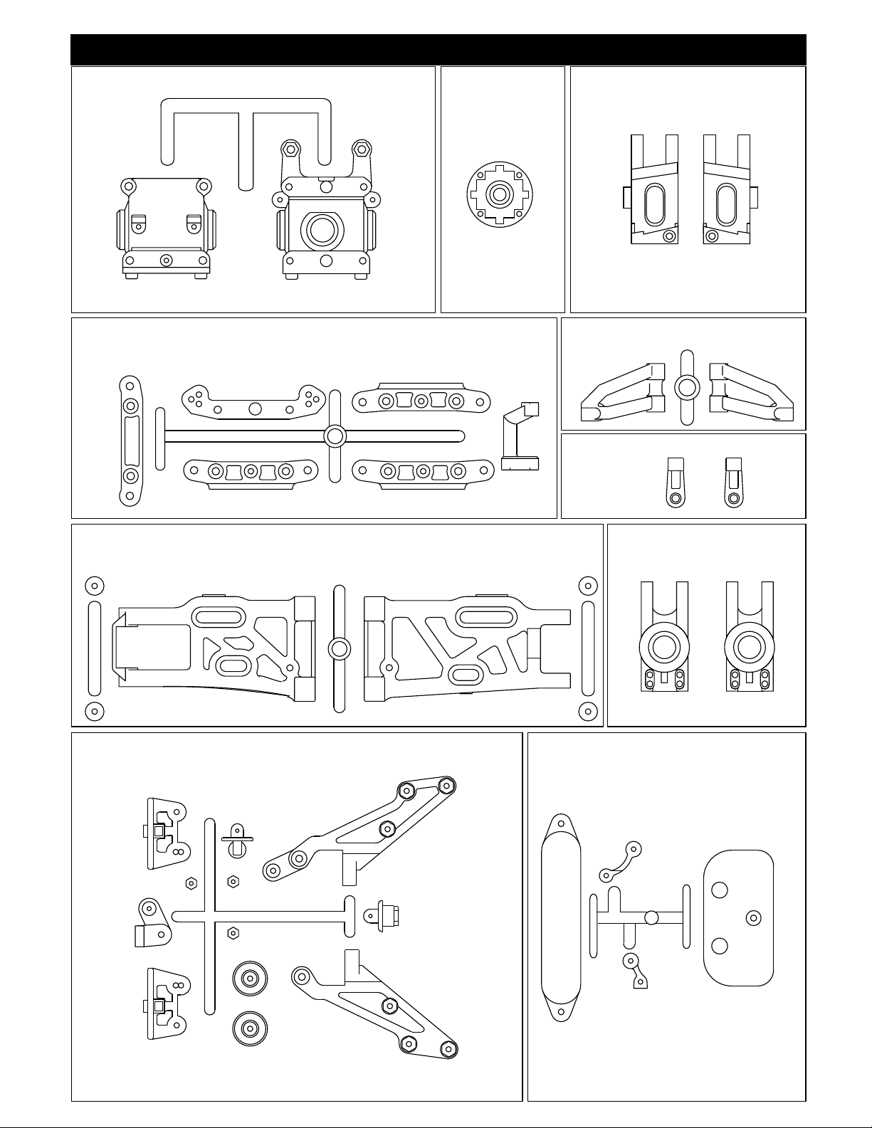
GEAR BOX PLASTIC PARTS
PLASTIC PARTS
40003
DIFF. CASE
PLASTIC PARTS
36060
FRONT C HUB PLASTIC PARTS
40015
ARM HOLDER PLASTIC PARTS
1
3
40020
FRONT AND REAR LOWER ARM PLASTIC PARTS
40016
UPPER ARM PLASTIC PARTS
2
Front Upper Arm Ball End
36690
36081
REAR UPRIGHT
40027
WING SUPPORT PLASTIC PARTS
40013 & 40048
FRONT BUMPER & BATTERY HOLDER
PLASTIC PARTS
40031
SERVO SAVER PLASTIC PARTS
40040
CENTER DIFF. MOUNT PLASTIC PARTS
PLASTIC PARTS
40047
RECEIVER BOX PLASTIC PARTS
CHASSIS BRACE PLASTIC PARTS
40019
40029 40065
40014
40056
SHOCK ABSORBER PLASTIC PARTS
40046
STONE GUARD PLASTIC PARTS
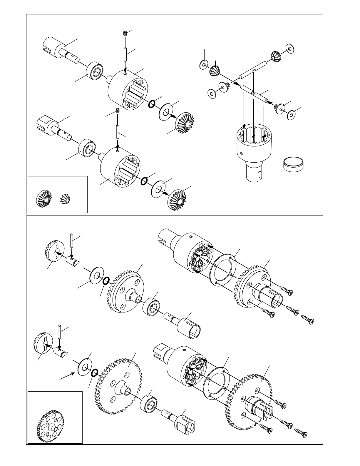
ASSEMBLY OF THE DIFFERENTIAL GEAR
40006
Cap Joint
94034
4x4mm
Set Screw
40010
2.5x13.8mm
Pin
40003
Diff. Case
30779
4 x 10mm
washer
40004
Diff. Gear
(Small)
30773
4mm
Cross pin
40004
Diff. Gear
(Small)
30779
4 x 10mm
washer
36053
8x16mm
Ball bearing
(Builds one differential for Center)
40005
Break
Cap Joint
36053
8x16mm
Ball bearing
OPTION: #49001 HD STEEL GEAR
SET, INSIDE DIFF.
94034
4x4mm
Set Screw
40003
Diff. Case
40010
2.5x13.8mm
Pin
ASSEMBLY OF THE DIFFERENTIAL CASE
40010
2.5x13.8mm
Pin
40004
Diff. Gear
(Large)
40012
6x15mm
Washer
*Use 6x15mm washer
to adjust the gear mesh.
( Builds two differentials for front and rear.)
40009
P6
O-Ring
40002
Large
Bevel Gear
40009
P6 O-Ring
40004
Diff. Gear
(Large)
40009
P6
O-Ring
36053
8x16mm
Ball bearing
40012
6x15mm
Washer
40012
6x15mm
Washer
40004
Diff. Gear
(Large)
40006
Cap Joint
30779
4 x 10mm
washer
40004
Diff. Gear
(Small)
40011
Diff. Gasket
30773
4mm
Cross pin
40002
Large
Bevel Gear
40004
Diff. Gear
(Small)
Note: It is very important to add
or remove the #30779 washer if
the gear mesh is too tight or
too lose.
* Apply diff. gear grease to the
differential during assembly.
* Fill the diff. the case to
approx 70% with grease.
30779
4 x 10mm
washer
40010
2.5x13.8mm
Pin
40004
Diff. Gear
(Large)
*Use 6x15mm washer
to adjust the gear mesh.
OPTION:
#49016 SPUR GEAR 50T, HD
#49030 SPUR GEAR 50T, HD SPECIAL
#49032 SPUR GEAR 51T,HD
(Builds one differential for Center)
40012
6x15mm
Washer
40009
P6
O-Ring
40001
47T
Spur Gear
36053
8x16mm
Ball bearing
40005
Break
Cap Joint
40011
Diff. Gasket
40001
47T
Spur Gear
94020
3x12mm
Flat Head
Tapping Screw
94020
3x12mm
Flat Head
Tapping Screw
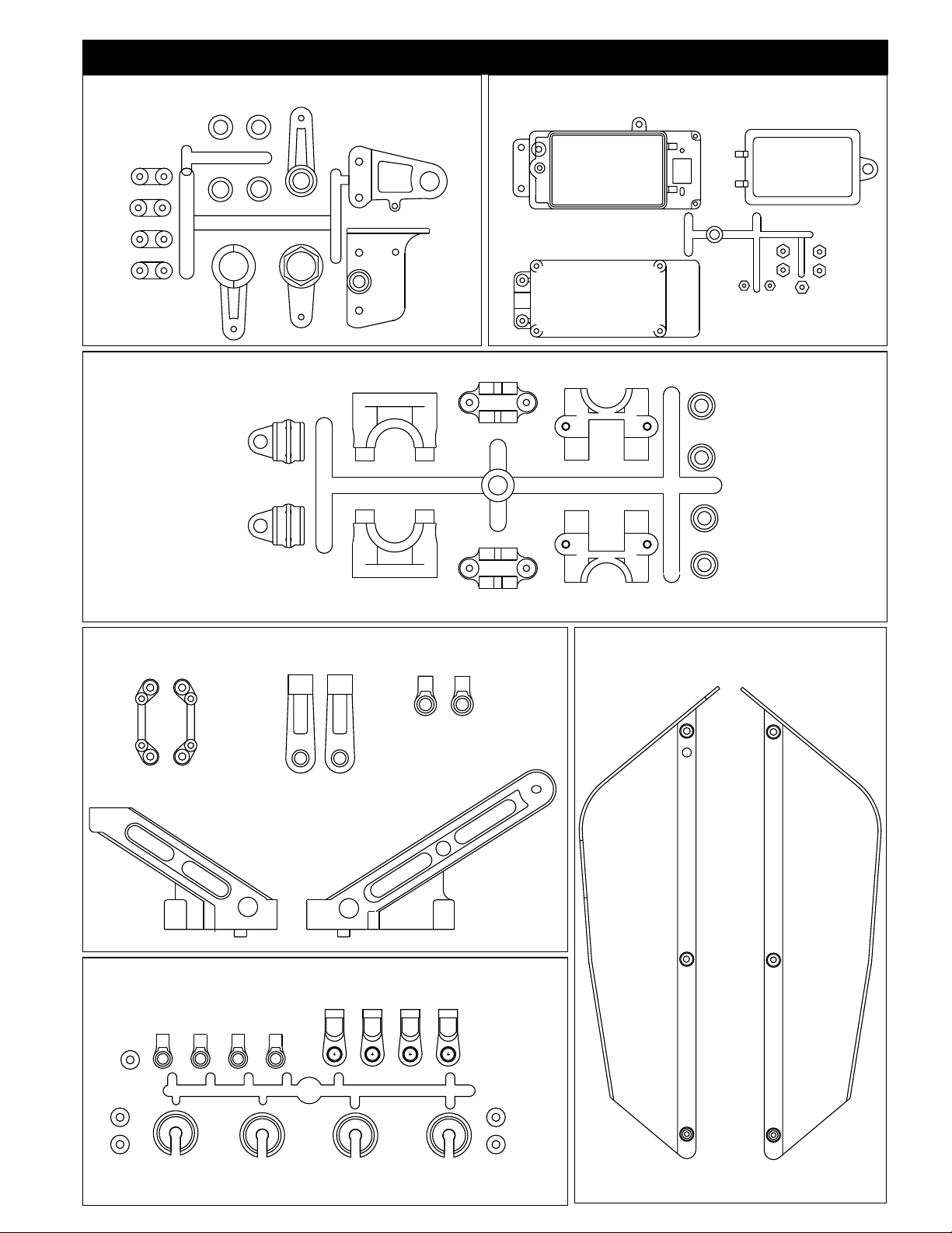
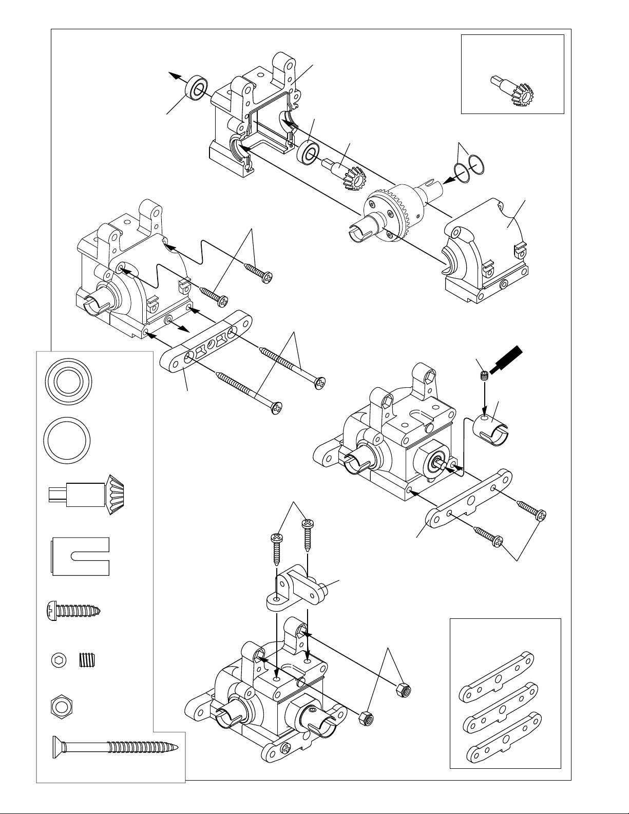
ASSEMBLY OF THE FRONT GEAR BOX
36053
8X16mm
Ball bearing
36053
8X16mm
Ball bearing....4
40024
13x16x0.2mm
Shim..............2
40024
13x16x0.2mm
Shim
40017
Gear Box
36053
8X16mm
Ball bearing
40021
14TSmall
Bevel Gear
OPTION: #49012 PINION GEAR
13TOOTH
40024
13x16x0.2mm
Shim
* Adjust the backlash
with the shims.
40017
Gear Box
40021
14T Small
Bevel Gear..............1
ASSEMBLY OF THE FRONT ARMS HOLDER
94011
4x15mm
Tapping Screw
(Small Head)
MISC. SCREW BAG
40067
94011
4x15mm
Tapping Screw........................2
90026
5x5mm
Set Screw......1
40022
Front Lower Arm
Holder (Front)
Use shims to adjust gear
mesh.
94014
4x45mm
Tapping Screw
(Small Head)
40015
Front Lower arm
Holder (Rear/Plastic)
OPTION: #49002 CNC 7075
FRONT LOWER ARM HOLDER
nt
ew
e
m
Scr
e
C
90026
5x5mm
Set Screw
36730
Cap Joint
94027
4x16mm
Flat Head
Tapping Screw
36730
Cap Joint................................1
94027
4 x 16mm
Flat Head
Tapping Screw.......................4
94014
4x45mm
Tapping Screw........................2
40015
Front Upper arm
Holder (Rear/Plastic)
94027
4x16mm
Flat Head
Tapping Screw
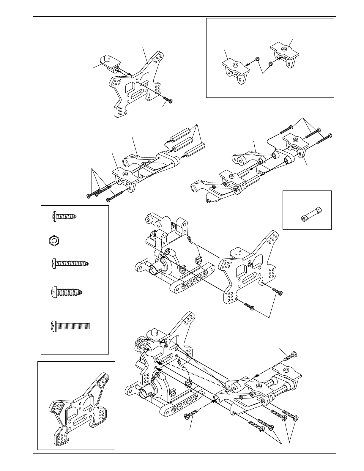
ASSEMBLY OF THE FRONT SHOCK TOWER
94042
4mm
Nylon Nut
40014
Front
Shock Tower
94011
M4x15
TP Screw
94004
M3x12
TP Screw
OPTION: #49003 CNC 7075 FRONT SHOCK
TOWER.
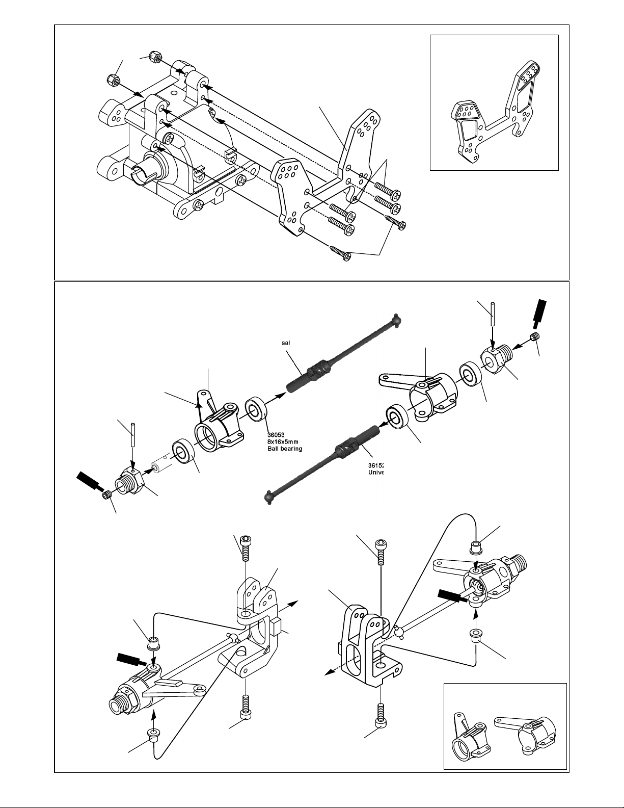
ASSEMBLY OF THE FRONT KNUCKLE ARMS
36152
Universal
36051
Alloy Front
Knuckle Arm
* "R" for right hand
side.
36055
2.5x17mm
Pin
S
c
C
r
ew
e
m
e
n
t
90026
5mm
Set Screw
* insert knuckle arm bushing
before assembly knuckle arm.
36120
Knuckle Arm
Bushing
36054
Alum.
Wheel Hub 8mm
R
36053
8x16x5mm
Ball bearing
36870
4x10mm
Cap Screw
36053
8x16x5mm
Ball bearing
36060
Front C Hub
(Right)
36870
4x10mm
Cap Screw
36060
Front C Hub
(Left)
36152
Universal
36051
Alloy Front
Knuckle Arm
L
36053
8x16x5mm
Ball bearing
Cem
Screw
ent
36055
2.5x17mm
Pin
L
36053
8x16x5mm
Ball bearing
36120
Knuckle Arm
Bushing
nt
e
Screw
Cem
90026
5mm
Set Screw
36054
Alum.
Wheel Hub 8mm
Apply screw
cement into
Hole, not
screw or
bushing.
Apply screw
cement into
Hole, not
screw or
bushing.
Scre
Cem
w
ent
36120
Knuckle Arm
Bushing
36870
4x10mm
Cap Screw
36870
4x10mm
Cap Screw
36120
Knuckle Arm
Bushing
OPTION: #36516 CNC ALUM
STEERING KNUCKLES.
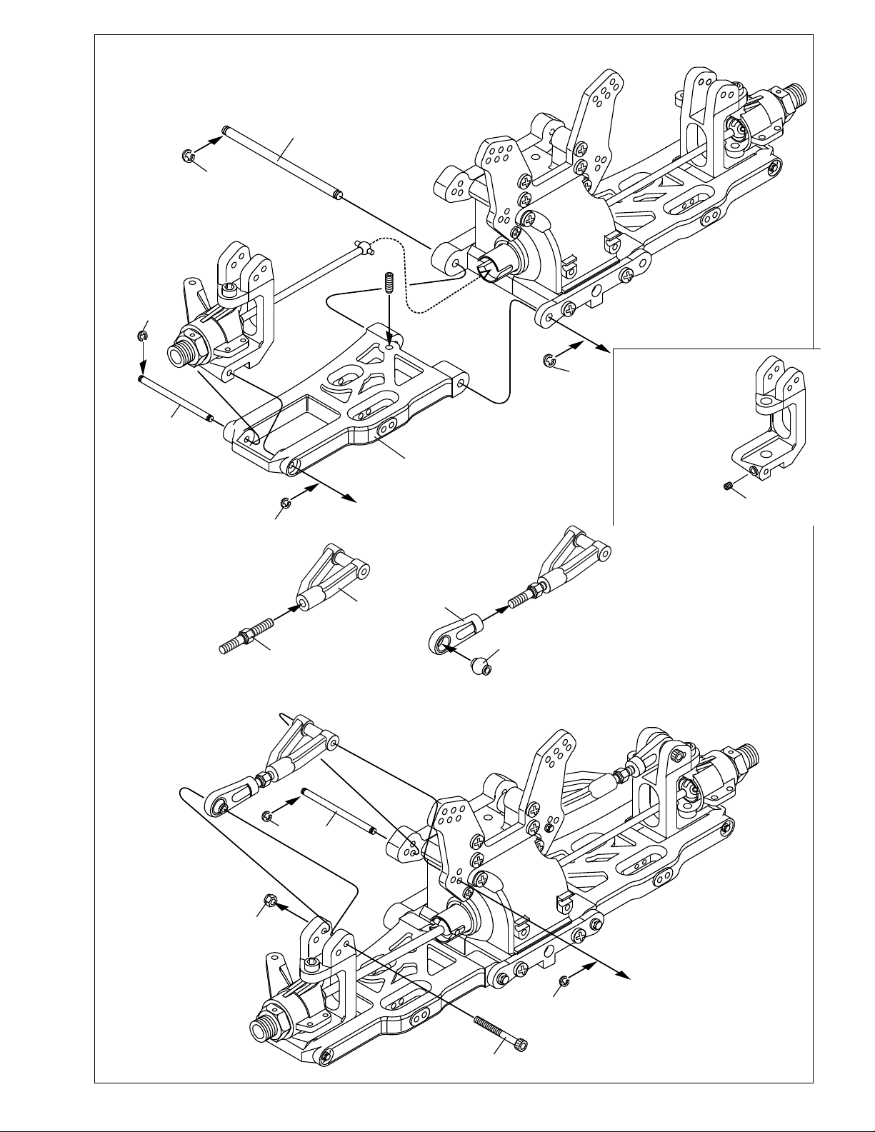
ASSEMBLY OF THE FRONT SUSPENSION ARMS
40023
Lower Arm Shaft (4mm)
90021
3mm
E-Ring
* A 4 x 10mm set screw is used
to adjust the ride height.
4X10mm
Set Screw
90020
2.5mm
E-Ring
90021
3mm
E-Ring
SPECIAL NOTE
36170
Arm Shaft
3mm
90020
2.5mm
E-Ring
36860
5x40mm
Turnbuckle
90020
2.5mm
E-Ring
36170
Arm Shaft
3mm
40016
Front
Upper Arm
40020
Front
Lower Arm
36690
7mm
Plastic Arm
Ball End
36850
7mm Ball
Screw in the 3mm set screws
to lock in the hinge pins.
*Note: Do not over tighten..
94033
3x3mm
Set Screw
94041
3mm
Nylon Nut
3x25mm
Set Screw
90020
2.5mm
E-Ring
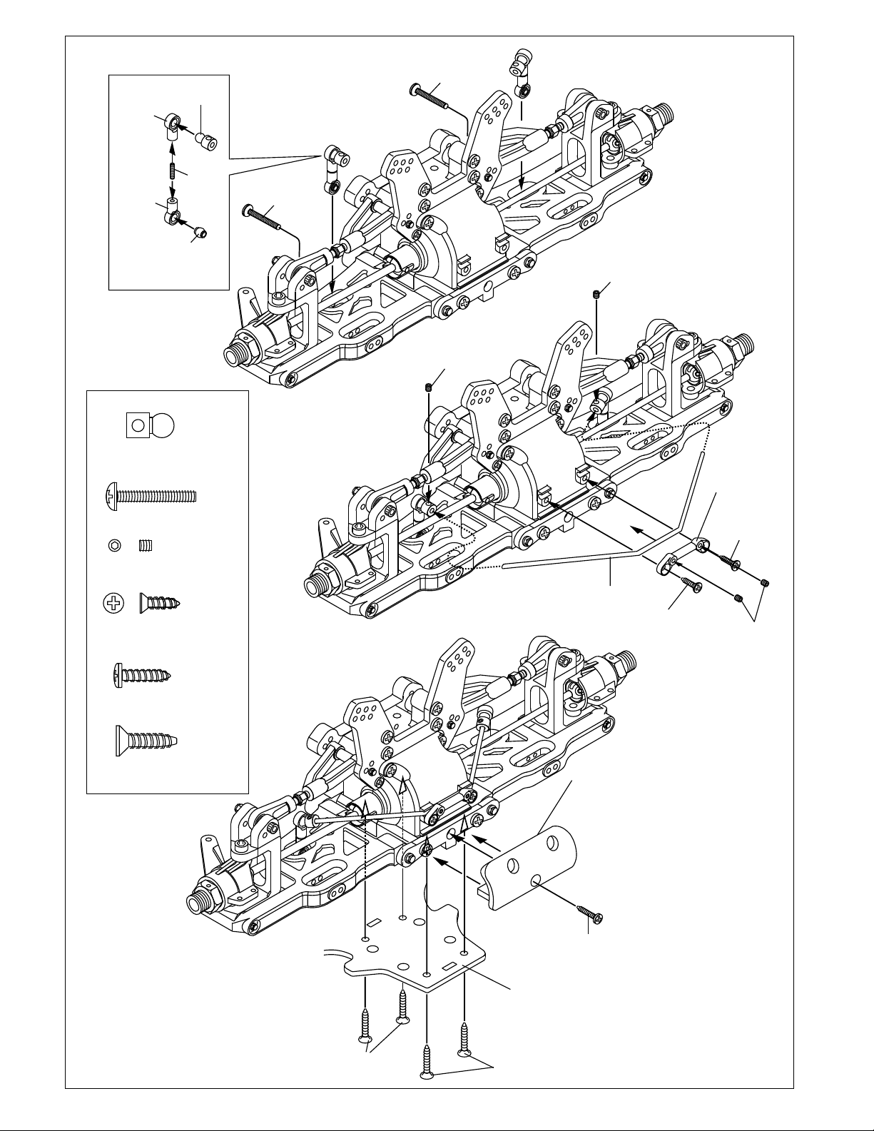
ASSEMBLY OF THE FRONT STABILIZER
40029
Stabilizer
Ball End
40029
Stabilizer
Ball End
30341
Stabilizer Ball
94035
3x8mm
Set Screw
30401
6mm
Ball End
30341
Stabilizer Ball..........2
94007
3 x 20mm
Screw ......................2
94033
3 x 3mm
Set Screw..............4
94019
3 x 10mm
Flat Head
Tapping Screw........2
94007
3x20mm
Screw
94007
3x20mm
Screw
94033
3x3
Set Screw
94033
3x3
Set Screw
40019
Stabilizer
40018
Stabilizer
Mount Plastic
94019
3x10mm
Flat Head
Tapping Screw
94019
3x10mm
Flat Head
Tapping Screw
94033
3x3mm
Set Screw
94004
3 x 12mm
Tapping Screw..........1
94027
4 x 16mm
Flat Head
Tapping Screw..........4
94027
4x16mm
Flat Head
Tapping Screw
40064
Chassis
Hard Coated
94027
4x16mm
Flat Head
Tapping Screw
40013
Front
Bumper
* Insert the front bumper
before assembly.
94004
3X12mm
Tapping Screw
ASSEMBLY OF THE REAR GEAR BOX
36053
8X16mm
Ball bearing
94027
4X16mm
Tapping Screw
(Small Head)
40017
Gear Box
36053
8X16mm
Ball bearing
40068
4X45mm
Flat Head
Tapping Screw
40021
14T Pinion
Gear
OPTION: #49012 PINION GEAR
13TOOTH
40024
13x16x0.2mm
Shim
* Adjust the backlash
with the shims.
40017
Gear Box
36053
8X16mm
Ball bearing....4
40024
13x16x0.2mm
Shim..............2
40021
14T Pinion
Bevel Gear..............1
36730
Cap Joint.................1
94011
4 x 15mm
Tapping Screw
( Small Head )..........6
40015
Rear arm Holder
40068
4X10mm
Tapping Screw
(Small Head)
40027
Wing Stay
Mount
94042
4mm
Nylon Nut
40025
Rear
Lower Arm Holder
( 0 Degree)
5x4mm
Set Screw
w
e
ment
Scr
Ce
36730
Cap Joint
94011
4X15mm
Tapping Screw
(Small Head)
OPTION: #49007 CNC REAR
LOWER ANTI-SQUAT HOLDERS -
1.5; 2.0; 3.0 DEGREES.
5 x 5mm
Set Screw..............1
94042
4mm
Nylon Nut..............2
40068
4 x 20mm
Flat Head
Tapping Screw..........2
5
.
1
2
3
ASSEMBLY OF THE WING STAY
( Take the plastic part from #40027Rear Win Stay Set. )
40027
Rear
Body Mount
40026
Rear
Shock Tower
40027
Wing Mount
35313
3mm
Nylon Nut
40027
Wing Mount
*Insert the 3mm nylon nut
before assembly.
94007
3x20
Tapping Screw
94004
3 x 12mm
Tapping Screw........3
35313
3mm
Nylon Nut........2
94007
3 x 20mm
Tapping Screw............6
40027
Wing Mount
40027
Wing Stay
( Left )
94004
3x12mm
Tapping Screw
40027
Wing Stay
Post
40027
Wing Stay
( Right )
94007
3x20
Tapping Screw
40027
Wing Mount
OPTION: #49023 CNC ALIM.
POSTS, WING MOUNT
94011
4 x 15mm
Tapping Screw
( Small Head )............2
4 x 15mm
Tapping Screw
( Small Head )............4
OPTION: #49004 CNC 7075 REAR
SHOCK TOWER
94011
4x15mm
Tapping Screw
( Small Head )
94004
3x12mm
Tapping Screw
94011
4x15mm
Tapping Screw
( Small Head )
94012
4x20mm
Screw
( Small Head )
 Loading...