

OFNA Racing Nexx10sc User Manual


IMPORTANT-READ THIS BEFORE RUNNING
1.Before Starting
•Please read manual carefulyl (With a parent, guardian or a responsible adult if necessary).
2.While Operating
•Any running area you choose must be dry. Do not run vehicle near any water or wet areas.
•Do not run on public streets. It is very easy to have the car run over or be damaged by hitting the curb.
•Do not operate the car in tight confined places. The vehicle is very fast and will easily hit something.
•Do not run near people or animals. The car is very fast and could easily seriously injured someone.
•Do not operate the car at night. You will not be able to drive it safely.
3.Before Operating
•Make sure that all screws and nuts are properly tightened.
•Always use fresh batteries for your transmitter and receiver before running the car. If the radio does
not have full control of the car with steering, throttle and brake. Do not run it until corrected. Failure
to correct this will result in possible injury and damage to the car or property.
We strongly recommend using a failsafe. But remember failsafe does not protect all power is lost
in vehicle.
•Please confirm the steering and throttle is at neutral position.
4.Check Your Vehicle After Runing
•Turn OFF receiver first, then turn OFF transmitter. This will prevent the car from losing control.
•After running radio controlled car, it is necessary to perform routine maintenance.
5.Battery Safety
•Please be careful when handling the battery. It will be hot after running. If the wire is frayed, a short
circuit can cause a fire.
WARNING: To avoid a possible fire hazard, always unplug the battery. Do not leave your vehicle
unattended with the battery plugged.

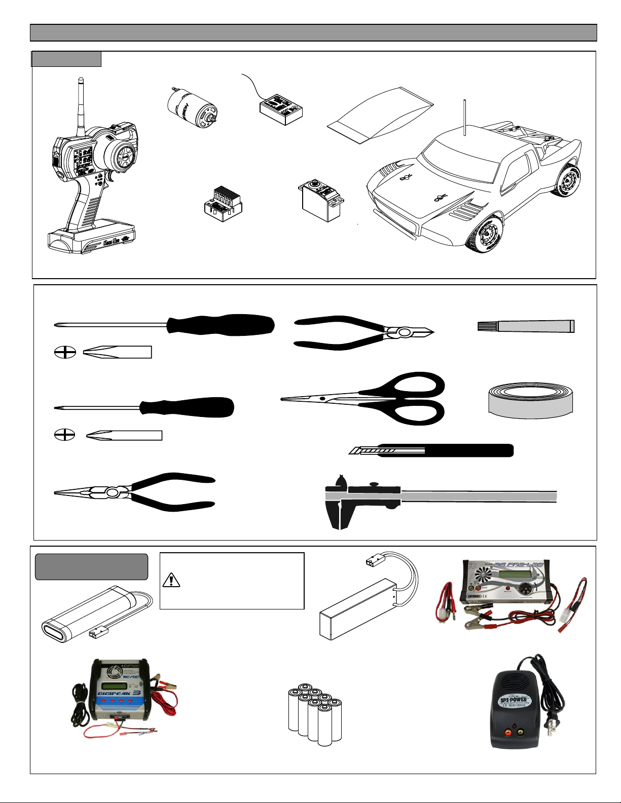
Components
OVERVIEW
Parts Bag
Transmitter
Radio Control Car
12T/550 Brushed Motor
B4222
Servo
Brush Electric Speed
Controller
TOOLS NOT INCLUDED IN THE KIT
Cutter
Phillips Type Screw Drivers ( L )
Curved Scissors
Part# 91009
Phillips Type Screw Drivers ( S )
Needle Nosed Pliers
Craft Knife
Precision Caliper
Instant Cement
CA Part # 10239
Masking Tape
Equipment Needed
6-Cell 7.2V Ni-Mh Battery
Ni-Mh/Lipo AC/DC 5amp
Battery Charger
Part# 91849
*Can use 7.2V 6-Cell Ni-Mh battery pack or 7.4V Li-Po
battery (hard case). Other type of batteries may cause
damages to your electronic speed controller and motor.
*It is important that you read all precautions and instructions
supplied by the charger and battery manufacturers. Make
sure you understand how to use your batteries correctly
and use them with required chargers.
CAUTION
*Be aware that Hong Nor Enterprise shall not be liable for
any indirect, incidental or consequential damages caused
by inappropriate installation or use of batteries in Hong
Nor models.
7.4V L i-Po Battery(Hard Case)
8 "AA" Type
Batteries
L Battery Charger
i-Po
Part# 91853
Power Supply
Part # 92135
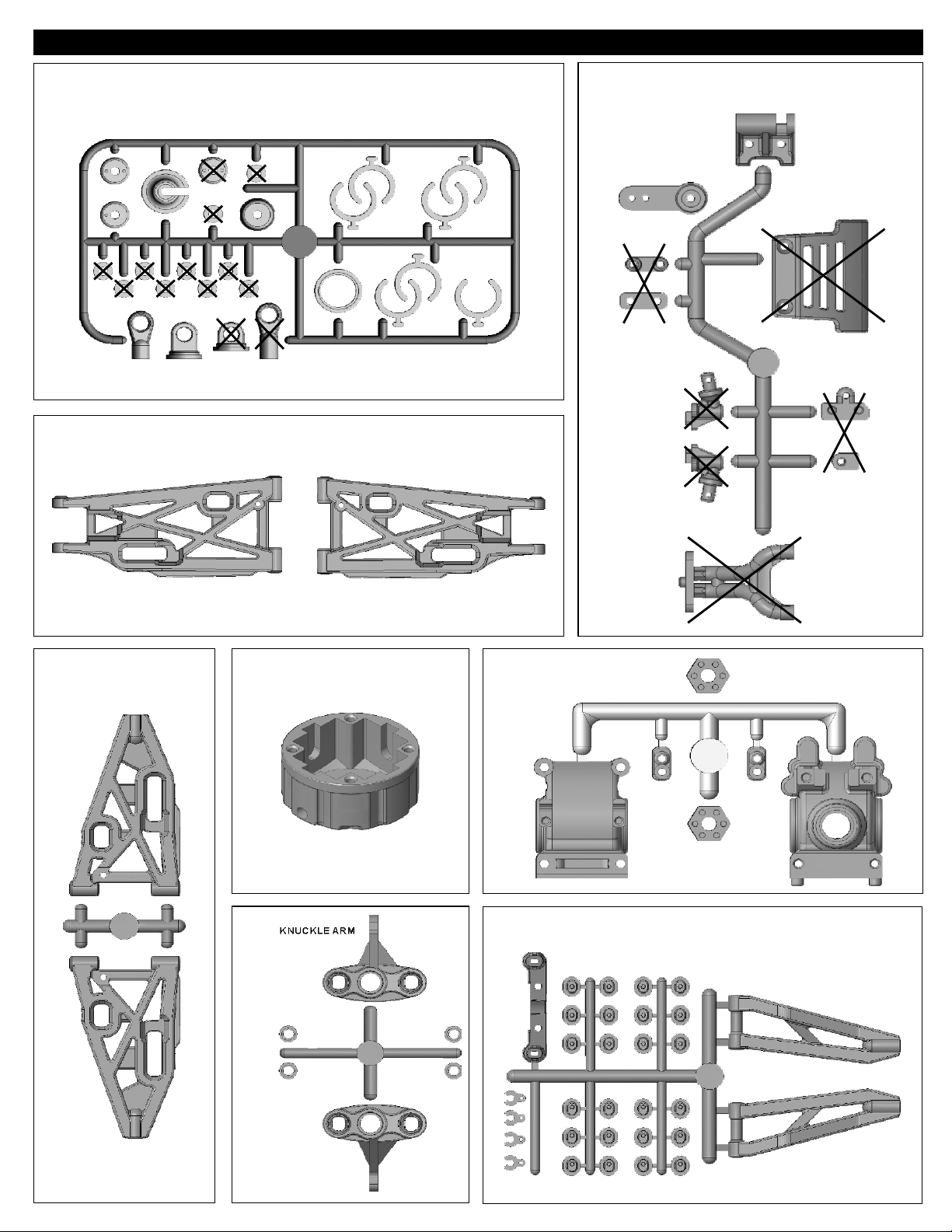
PLASTIC PARTS FOR USE
37100
SHOCK ABSORBER
40970
REAR LOWER ARM
40921
BUMPER & RADIO TRAY POST & BODY POST
40931
40835
LOWER ARMFRONT
DIFF. CASE
40932
FRONT KNUCKLE ARM
40840
FRONT & REAR GEAR BOX
40930
FRONT UPPER ARM AND ARM HOLDER
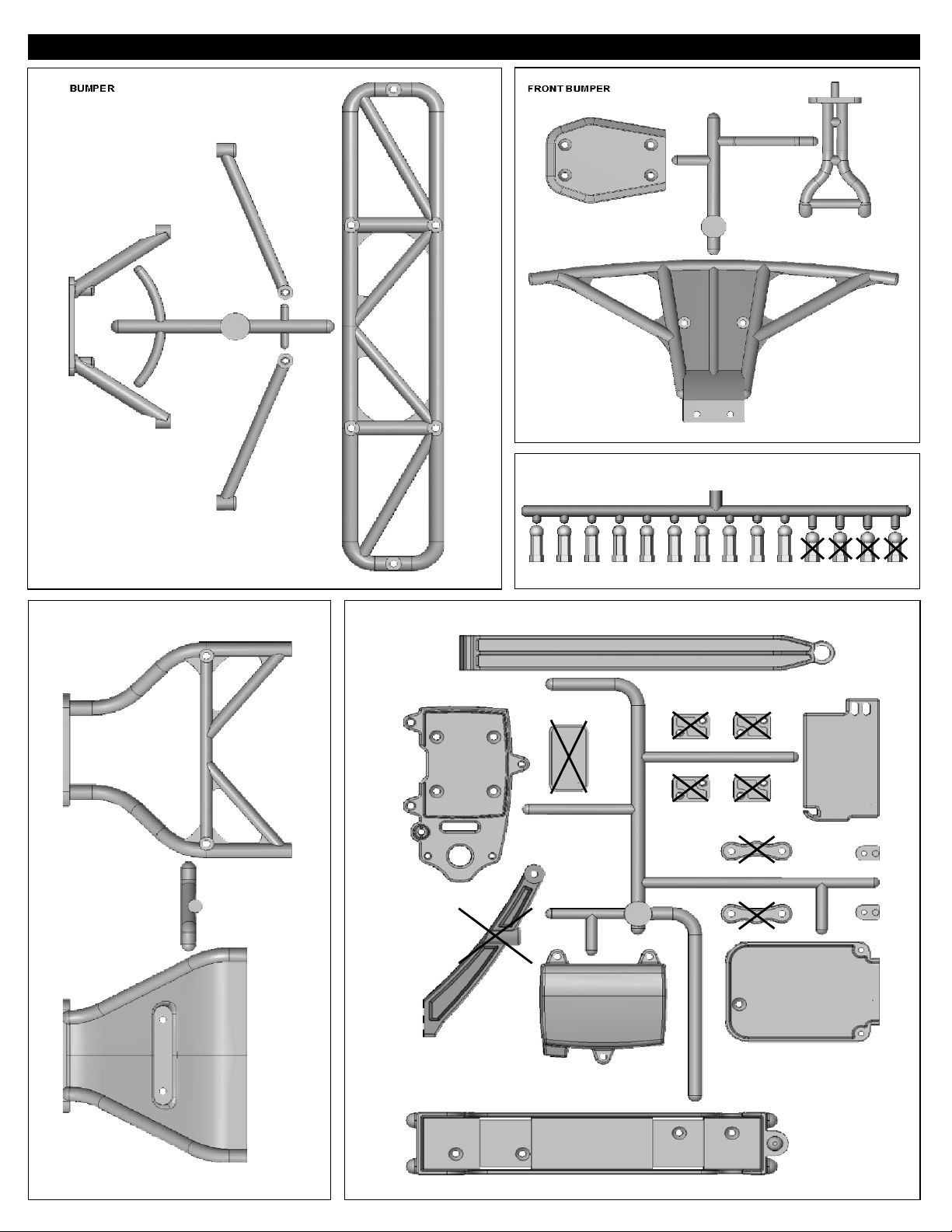
PLASTIC PARTS FOR USE
40944
REAR BUMPER
40943
FRONT BUMPER
37381
BALL END (4mm)
40945
REAR BUMPER BRACE
40946
BATTERY CASE & RECEIVER BOX
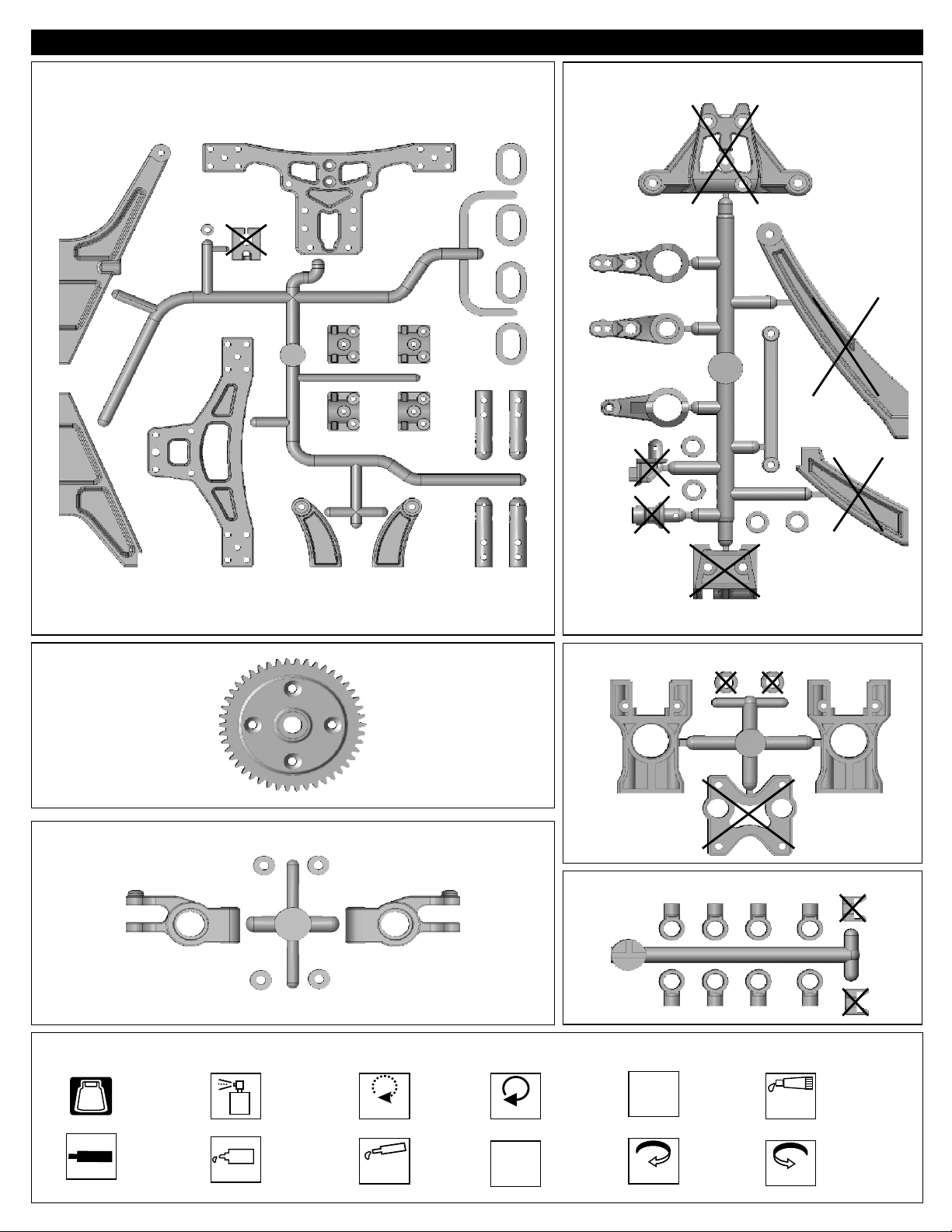
PLASTIC PARTS FOR USE
40947
BODY POST & CENTER BRACE
40834
SERVO SAVER
40948
SPUR GEAR (46T)
40843
REAR UPRIGHT
SYMBOL USED THROUGHOUT THE INSTRUCTION MANUAL
Parts Bag Used
BAG
Degrease With
Motor Spray
Do Not
Over Tighten
Do Not
Over Tighten
Tighten
40844
CENTER DIFF. MOUNT
40848
STABILIZER BALL END
Tighten
Ensure
Free
Movement
Ensure Free
Movement
Contact
Adhesive
Contact Adhesive
S
Cem
cr
ew
en
t
Cement
Apply OilApply Screw
Oil
Apply
Grease
Apply Grease
1:1
True-To-Scale
Rotate
Direction
Clockwise
Rotation
Rotate
Direction
Anti-clockwise
Rotation
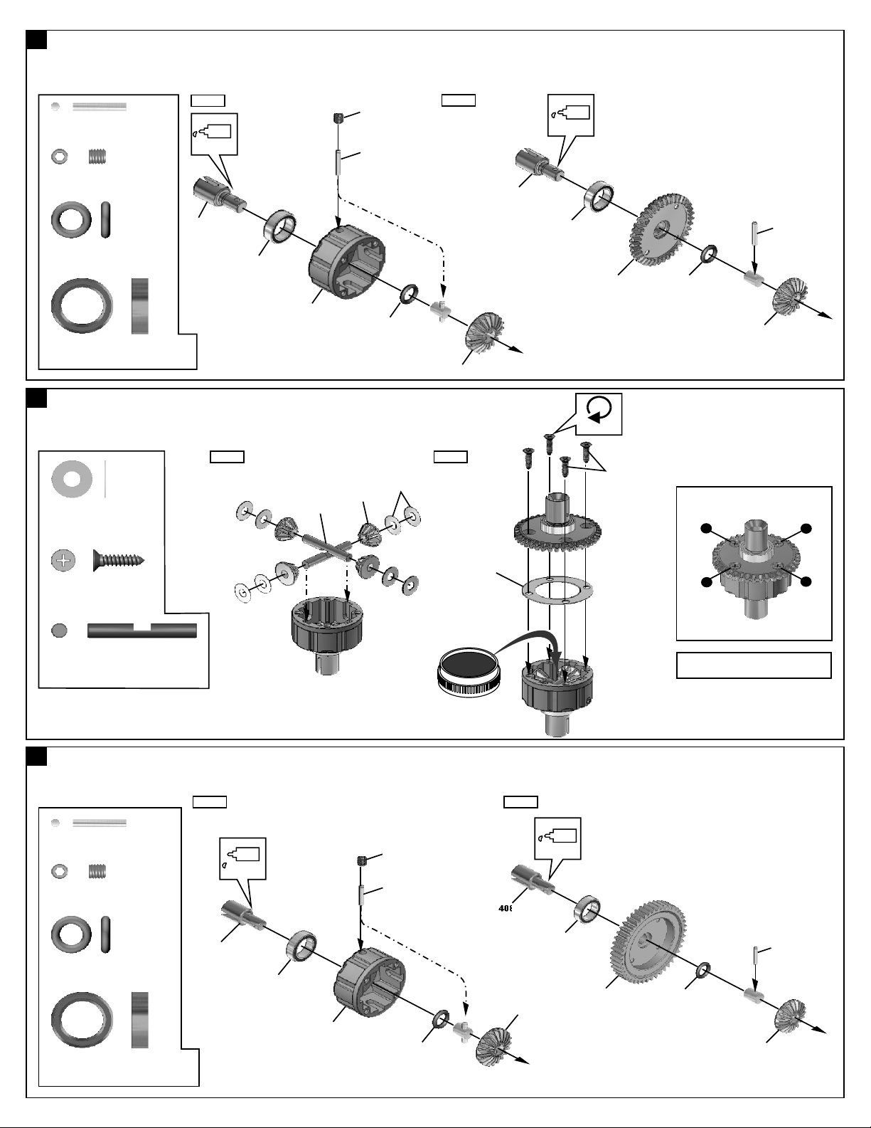
1
ASSEMBLY OF THE FRONT AND REAR DIFF.
*Build two differentials for front and rear.
Step 1
30780
2x12.8mm Pin
94034
4x4mm
Set Screw
40009
P6 O-Ring
37450
10x15mm Ball Bearing
2
ASSEMBLY OF THE FRONT AND REAR DIFF.
*Build two differentials for front and rear.
30776
4x10mm Washer
.....x4
.....x2
.....x4
.....x16
Oil
40808
37450
40835
.....x4
Step 1 Step 2
30773
40805
4x4 mm
30780
40009
30776
Step 2
40805
40808
Oil
37450
40803
Tighten
2.6x10mm
30780
40009
40805
Tighten the diff screws in this order.
1
3
94046
2.6x10mm
Flat Head Screw
30773
4mm
Cross Pin
3
ASSEMBLY OF THE CENTER DIFF.
30780
2x12.8mm Pin
94034
4x4mm
Set Screw
40009
P6 O-Ring
37450
10x15mm Ball Bearing
.....x8
.....x4
Step 1 Step 2
.....x2
Oil
.....x1
40808
.....x2
.....x2
37450
40835
4x4 mm
30780
40009
40011
Grease
40808
40805
Oil
37450
40948
4
*Apply grease to the differential gear
during assembly.
30780
40009
40805
2
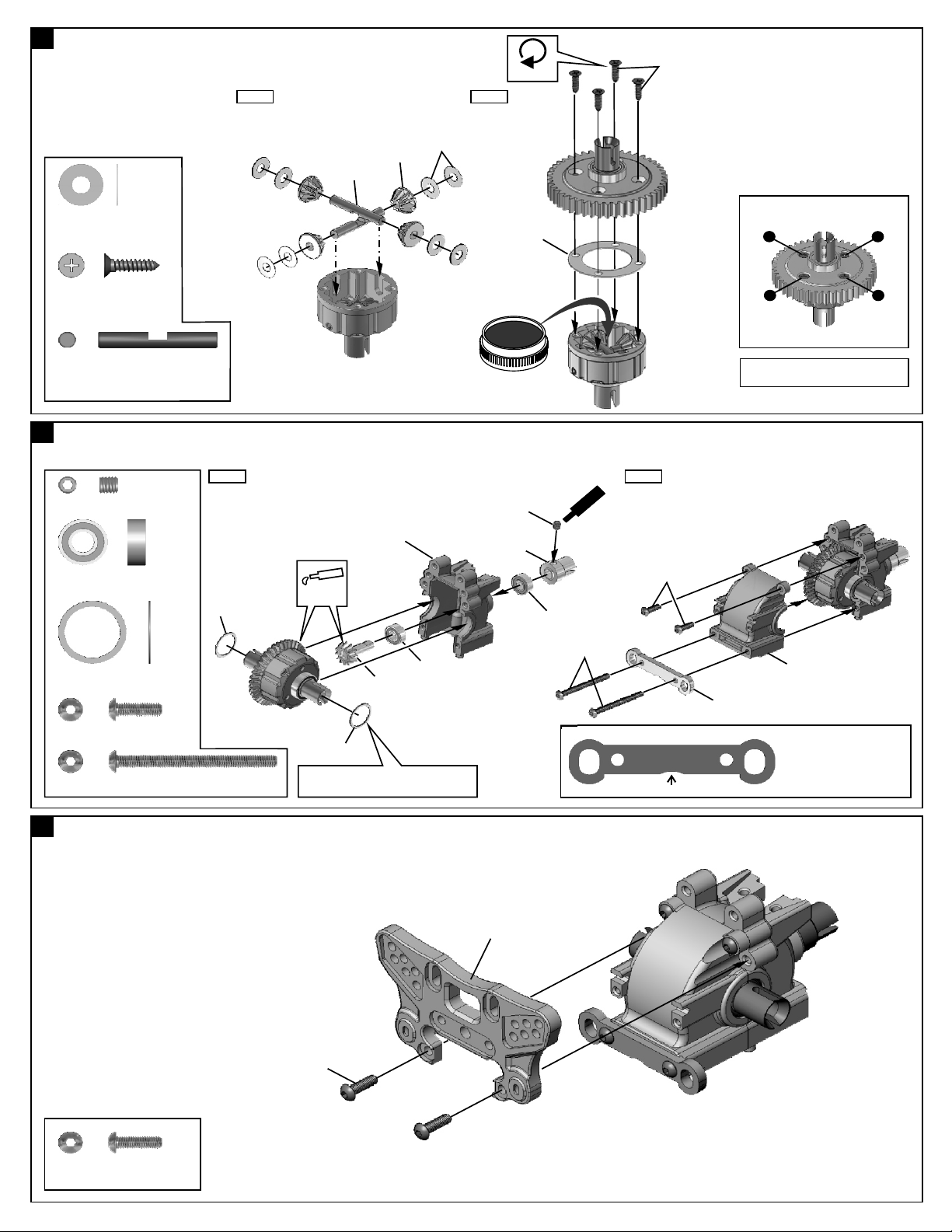
4
ASSEMBLY OF THE CENTER DIFF.
Step 1 Step 2
30773
40805
30776
Tighten
2.6x10mm
30776
4x10mm Washer
94046
2.6x10mm
Flat Head Screw
30773
4mm
Cross Pin
5
ASSEMBLY OF THE FRONT GEAR CASE
94034
4x4mm Set Screw
37430
5x11mm Ball Bearing
38254
12x15x0.25mm Shim
94003
3x10mm Hex Screw
94043
3x35mm Hex Screw
.....x8
.....x4
.....x2
.....x1
.....x2
.....x2
.....x2
.....x2
Step 1 Step 2
Apply
38254
Grease
*Adjust the backlash with the shims.
38254
40804
40840
37430
40011
Grease
4x4mm
40806
37430
w
e
m
Scr
Ce
3x35mm
Tighten the diff screws in this order.
1
4
*Apply grease to the differential gear
during assembly.
nt
e
3x10mm
40840
40813
1:1
Down
* Notice the direction of
the front lower arm holder.
3
2
6
ASSEMBLY OF THE FRONT SHOCK STAY
3x10mm
94003
3x10mm
Hex Screw
.....x2
40870
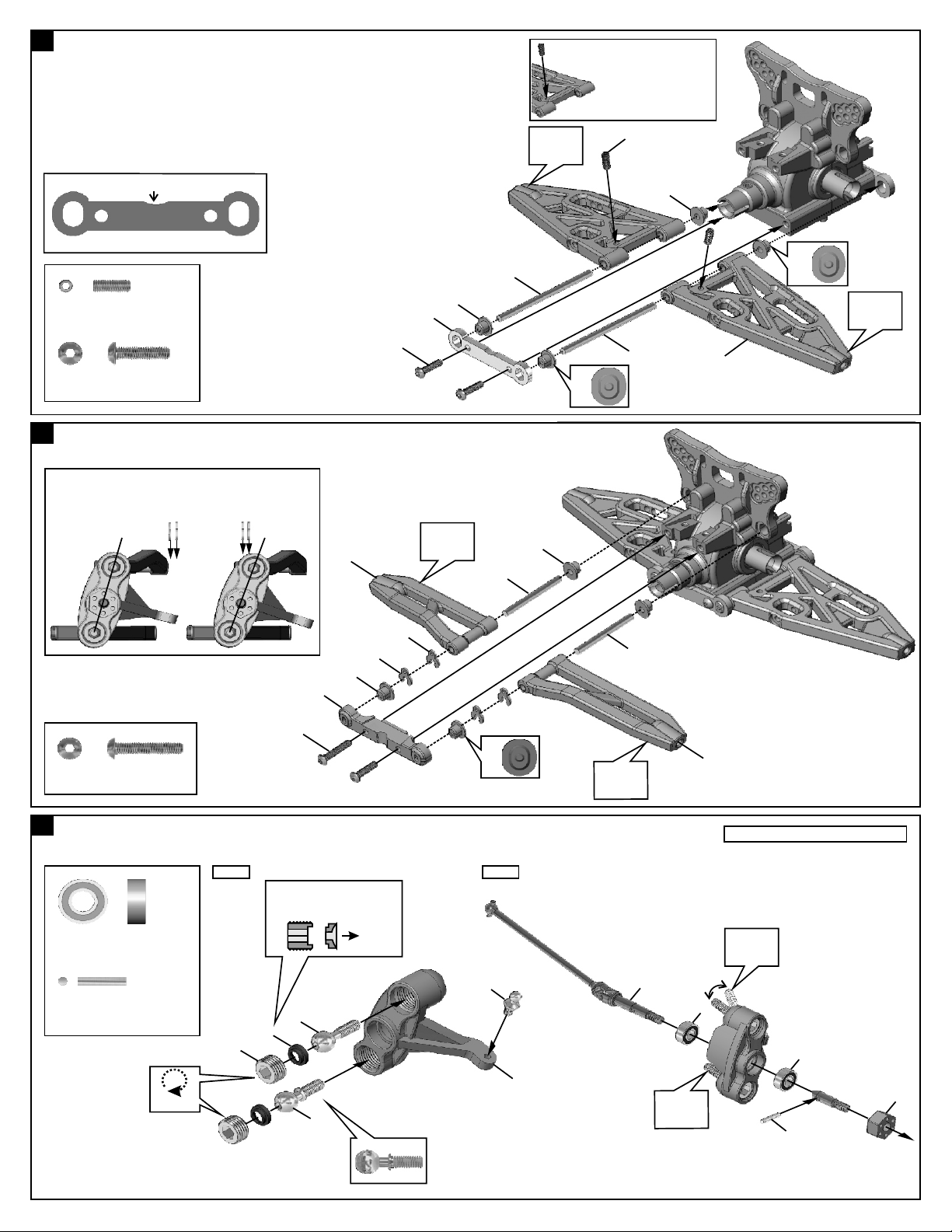
7
ASSEMBLY OF THE FRONT LOWER ARMS
* A 3x8mm set screw is used to
adjust Droop.
* Notice the direction of the front lower arm holder
in rear.
Up
1:1
94035
3x8mm
Set Screw
94004
3x12mm
Hex Screw
8
ASSEMBLY OF THE FRONT UPPER ARMS
*Adjust the caster angle by changing the position of the
caster angle spacer on the top arm.
*Caster angle adjustments can be made from 20 degrees
to 24 degrees.
20 Degree 24 Degree
.....x2
.....x2
40930(Left Side)
3x12mm
40930
40813
Ensure
Free
Movement
40825
40933
Ensure
Free
Movement
40930
1:1
3x8mm
40825
40930
40931
1:1
Ensure
Free
Movement
3x15mm
94005
3x16mm
Hex Screw
9
ASSEMBLY OF THE KNUCKLE ARMS
37430
5x11mm Ball Bearing
37390
2x10.8mm Pin
.....x2
.....x4
.....x2
Step 1
*Notice the direction of the
plastic washer.
39140
40932
39150
40930
6
40930
(1mm)
40930
40930
(1mm)
1:1
37360
Step 2
40933
Ensure
Free
Movement
40875
40930(Right Side)
Assemble for both right and left side.
Ensure
Free
Movement
37430
37430
Do Not
Over Tighten
40934
40932
Ensure
Free
Movement
40840
37390
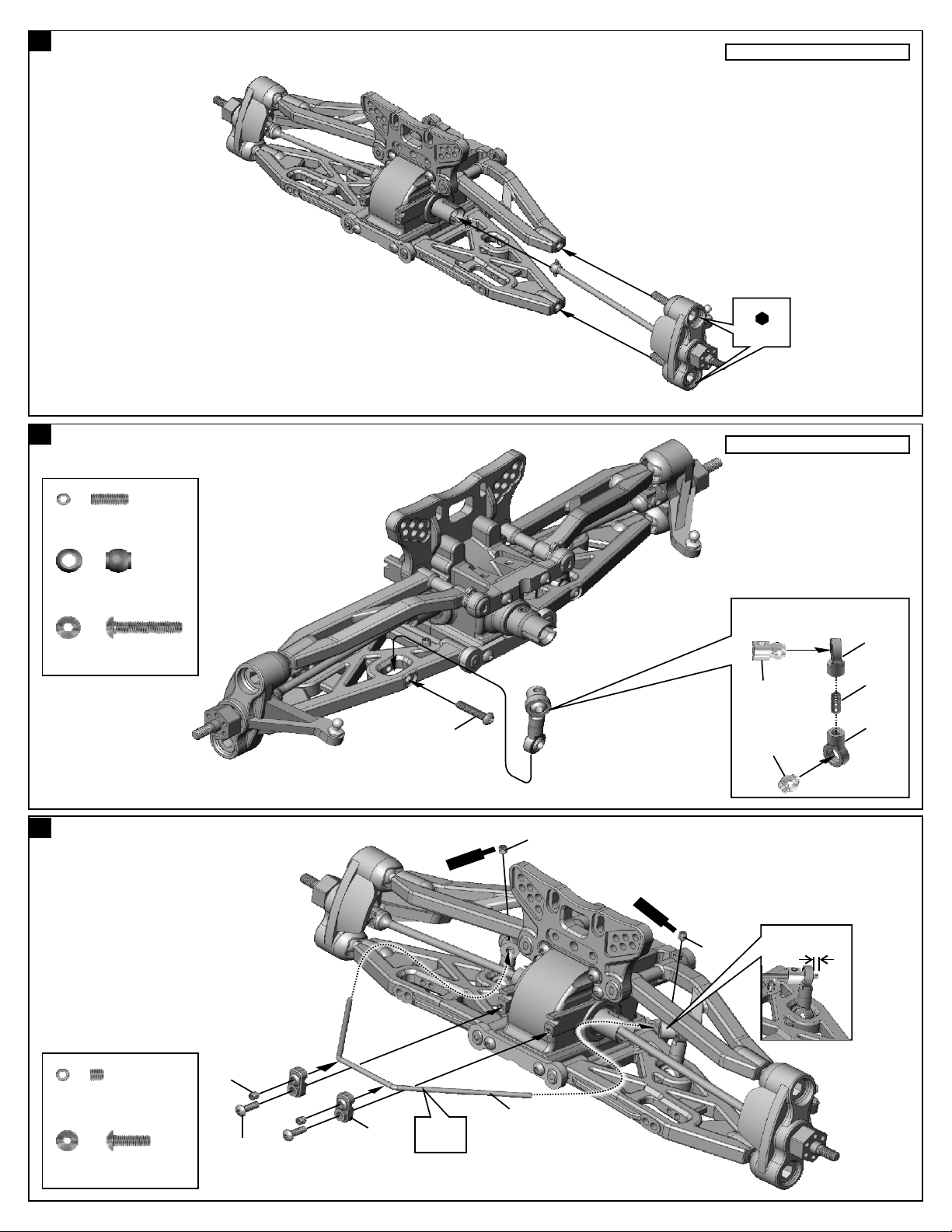
10
ASSEMBLY OF THE KNUCKLE AND FRONT SUSPENSION ARMS
11
ASSEMBLY OF THE FRONT STABILIZER
Assemble for both right and left side.
Use
2.5mm
Hex Wrench
Assemble for both right and left side.
94035
3x8mm
Set Screw
30403
6mm Ball
94005
3x16mm
Hex Screw
12
ASSEMBLY OF THE FRONT STABILIZER
.....x2
.....x2
.....x2
3x16mm
S
Ce
crew
Makes two rods for left and right
hand-side.
40848
30341
30403
3x3mm
t
en
m
S
Cet
r
ec w
emn
3x3mm
*Approx. 3.5mm
3x8mm
40848
94033
3x3mm
Set Screw
94044
2.5x8mm
Hex Screw
.....x4
.....x2
3x3mm
2.5x8mm
40840
Ensure
Free
Movement
40817
 Loading...