

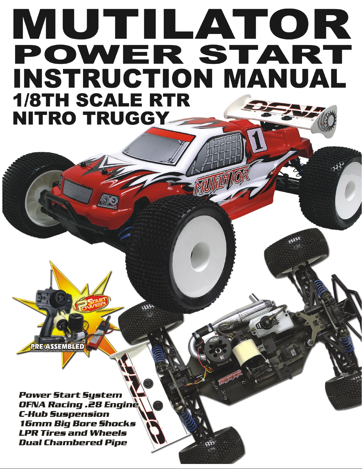
VER. 12-04-2008


MUST READ THIS BEFORE RUNNING
Running a nitro kit is fun and easy, but to make this a safe • Clean oil and dirt from chassis with a degreaser.
and good experience you must observe a few rules. This
kit is extremely fast, easily over 40MPH, and can seriously
injure someone if you are not careful.
Where to run car?
• Any running area you choose must be dry. Do not run
car near any water or wet dirt.
• Do not run on public streets. It is very easy to have the
car run over or damaged by hitting the curb.
• Do not operate car in tight confined places. The car is
very fast and will easily hit something.
• Do not run near people or animals.
and will too easily hit someone.
• Due noise, you will want to consider the surrounding
area when operating the car.
• Do not operate the car at night. You will not be able to
drive it without hitting something.
• Do not operate the car indoors. Engine exhaust is not
healthy.
Glow Fuel
• Glow fuel is poisonous!
• Glow fuel is flammable! label for additional precautions.
• Do not leave fuel bottle with lid off at any time.
• Do not use any fuel other than glow fuel in this engine. • Car Fuel tank - Never store fuel in car tank, it will ruin the
First Time Starting the Engine
Caution! When starting engine make sure the following is
observed.
• Set engine Master needle to 3 turns (rich setting) • DAMAGE DUE TO CAR RUN AWAY IS NOT A
• Do not do this alone, get an experienced friend to help at
first.
• Fill fuel tank, try not to spill fuel. Do not spill fuel on
receiver
• Hold car off the ground, so it will not runaway when first
starts
• Turn on Radio and check the linkage before starting
engine.
• Turn on car receiver battery switch.
• Always have an air filter on the carburetor to keep dirt
out.
The car is very fast
Precautions
• This kit is not a toy. Always run car with a second
person as a spotter and pitman.
• Hot Parts - The pipe, manifold, engine and head are very
hot and will cause burns.
• Rotating Parts - Keep hands away from the drive train,
wheels, and engine when engine is running.
• Radio - Check batteries life before running the car. If
radio does not have full control of the car with steering
and/or throttle/brake do not run until corrected. Failure to
correct this will result in possible injury and damage to the
car or property.
• Glow fuel - Do Not leave the glow fuel unattended with the
Lid off. Fuel contains Methanol and Nitro Methane and is
flammable and poisonous.
Store fuel in cool ventilated location. Refer the glow fuel
engine if left in tank.
• Always turn off the car BEFORE turning off radio.
WARRANTY ISSUE.
IF YOU DO NOT BREAK-IN ENGINE
CORRECTLY, MAINLY AT LOW RPM,
YOU WILL BREAK THE CONNECTING
ROD!
FAILURE TO NOT READ AND
Engine Break-in
• See Engine Page.
Emergency Stopping Engine When Running
• Remove air filter and cover carb. intake.
• Squeeze fuel line and hold until engine stops.
• With a rag, cover exhaust outlet.
Storing Car After Running
• Remove fuel from tank and fuel lines
• Turn off radio in car
• Put a few drops of after run in engine to keep it from
rusting.
FOLLOW BREAK-IN ENGINE
INSTRUCTIONS WILL VOID
WARRANTY!
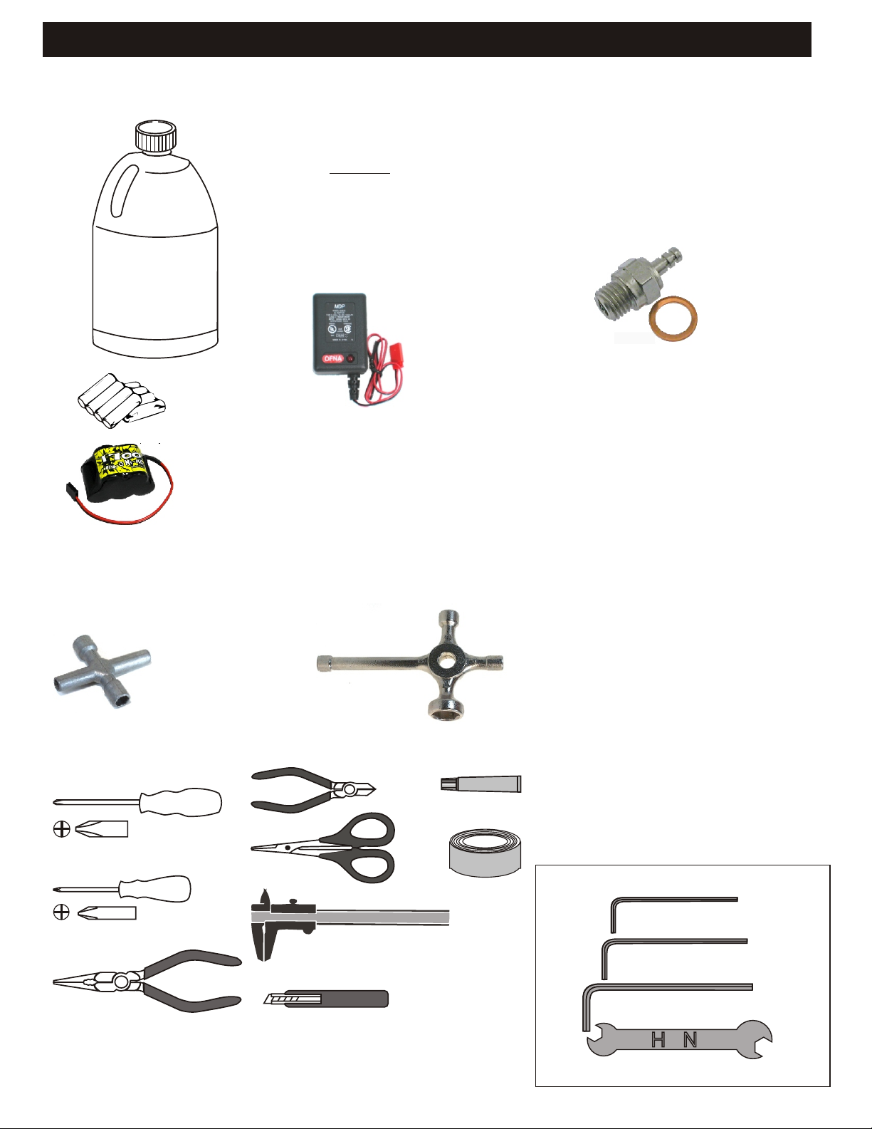
RTR KITS - REQUIRED FOR OPERATION
THINGS NEEDED
Glow Fuel
20%
AA Batteries ( 12 pcs )
You will need to buy a few items to start the engine and run the car.
• Use 20% nitro CAR fuel. Do not use airplane or heli fuels, they will
over heat engine.
• Buy LONG glow plugs, like OFNA Plug (#51009).
Use plugs without idle bar. Do NOT use plugs, like the MC-59 or OS-8
In your box you will find..
• #10162- Bottle, 250cc
• #10219 - Red “D” size glow heater
10195
7.2 Volt
Over-nite
Charger
You need to get batteries for the radio transmitter and the car receiver packs.
• Radio TX needs (8) eight AA batteries.
• Shaft Starter requires a 7.2Volt battery pack and charger OFNA #10195
• Car needs (4) four AA Ni-cad batteries 2000Mah or higher or (4) Alkaline., Alkaline type
batteries will work, but braking will be reduced and 30 minute life. The best for car, is to use a 5
cell hump receiver pack for increased voltage and longer life..
10214
Rec’v Bat.
Over-nite
Charger
51009 OFNA GLOW PLUG #3 RTR
#10202 Rec’v Bat.
NiHm Hump Pack,
see charger 10214.
Recommended Option:
You may want to upgrade the car battery pack to a Ni-Cad or NiHm 5 cell type(600AE). This will
give more run time. OFNA #10212 1400NiMh Hump Pack and NiHm Battery Charger #10214
TOOLS NOT INCLUDED IN KIT
Glow Plug & 17MM Cross Wrench
#10801 $6.95
Cross Wrench
#17109 $3.95
Phillips Type Screw Drivers ( L )
Phillips Type Screw Drivers ( S )
Cutter
Curved Scissors
91009 $5.95
Precision Caliper
Instant Cemment
Masking Tape
INCLUDED WITH KIT
1.5mm Allen Wrench
2mm Allen Wrench
Needle Nose Pliers
2.5mm Allen Wrench
Hobby Knife
4mm'5mm Allen Wrench
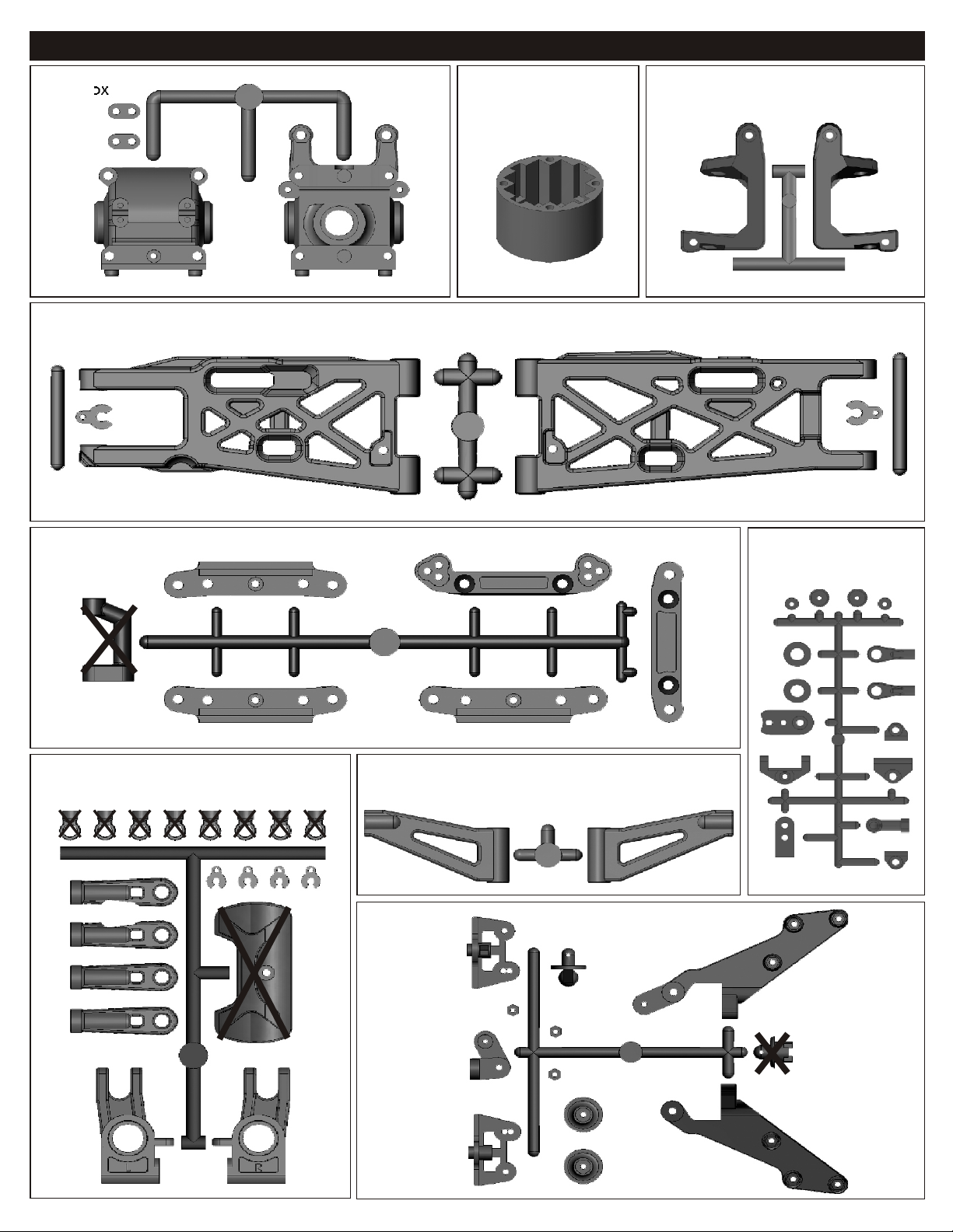
PLASTIC PARTS FOR USE
40017
GEAR BOX
40140
FRONT & REAR LOWER ARM
40003
DIFF. CASE
40536
FRONT C HUB
40015
ARM HOLDER
40540
REAR UPPER ARM & REAR WHEEL HUB
30802
THROTTLE LINKAGE
40015
FRONT UPPER ARM
40027
WING STAY
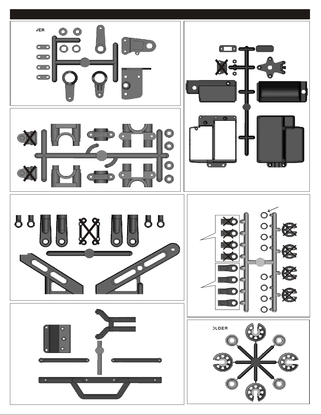
PLASTIC PARTS FOR USE
40031
SERVO SAVER
40040
CENTER DIFF. MOUNT
40541
RECEIVER BOX
40018/40029
CENTER BRACER
40137
BUMPER
40643
SHOCK PLASTIC BALL END
40643
Shock Plastic
Ball End
(Short)
40643
Shock Plastic
Ball End
(Long)
41008
SHOCK HOLDER
40643
Shock Cap
Washer
1
1
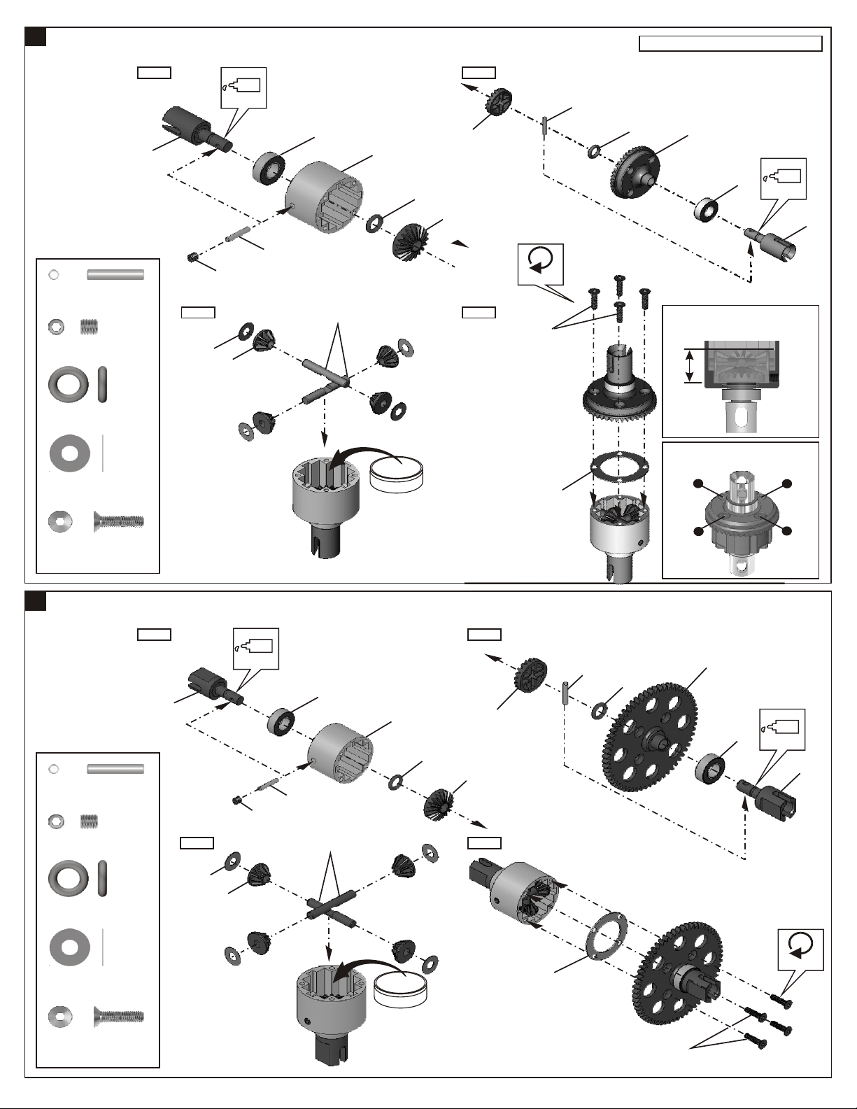
ASSEMBLY OF THE FRONT AND REAR DIFF.
Step 1 Step 2
Builds two differentials for front and rear.
40010
2.5x13.8mm
Pin
94034
4x4mm
Set Screw
40009
P6 O-Ring
30776
4x10mm
Washer
........x4
........x2
........x4
........x8
40006
Step 3
30776
4x4mm
40513
Oil
40010
36053
30773
40003
iff. O
40009
D
40010
40513
40513
Tighten
Step 4
3x12mm
il
40011
40009
49032
36053
Fill the diff oil just level with the
top of the satellite gears.
ョtウtェo・[、Jヲワョtウtセヲスウサ・ュュアォh・i。C
80%
Tighten the diff screws in this order.
スミィフケマ・ワカカァヌ、Wコチウオキ。C
1
Oil
40006
3
94020
3x12mm
Flat Head
Hex Screw
2
ASSEMBLY OF THE CENTER DIFF.
40010
2.5x13.8mm
Pin
94034
4x4mm
Set Screw
40009
P6 O-Ring
........x8
Step 1 Step 2
Oil
40005
........x2
4x4mm
........x1
........x2
Step 3 Step 4
30776
40513
40010
36053
30773
40003
40009
40513
40513
40010
40009
4
40134
36053
2
Oil
40005
30776
4x10mm
Washer
94020
3x12mm
Flat Head
Hex Screw
........x4
........x4
D f
Tighten
i
f .
Oi
l
40011
3x12mm
3
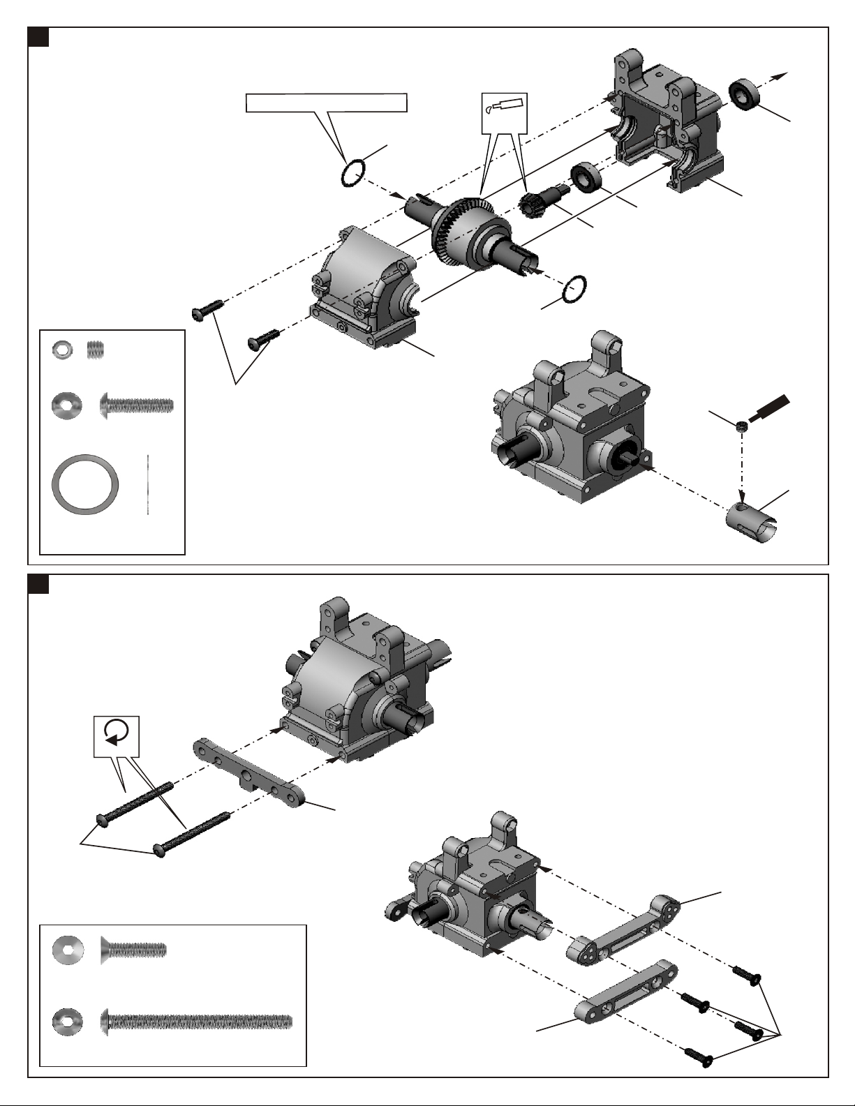
ASSEMBLY OF THE FRONT GEAR CASE
94036
5x4mm
Set Screw
94011
4x16mm
Hex Screw
........x1
........x2
。ッAdjust the backlash with the shims.
4x16mm
40024
40017
Apply
Grease
40024
49012
36053
5x4mm
40017
36053
nt
rew
e
m
Sc
Ce
36730
40024
13x16x0.2mm
Shin
4
ASSEMBLY OF THE FRONT ARMS HOLDER
4x45mm
........x2
Tighten
40022
40015
94027
4x16mm
Flat Head
Hex Screw
94014
4x45mm
Hex Screw
........x4
........x2
40015
4x16mm
5
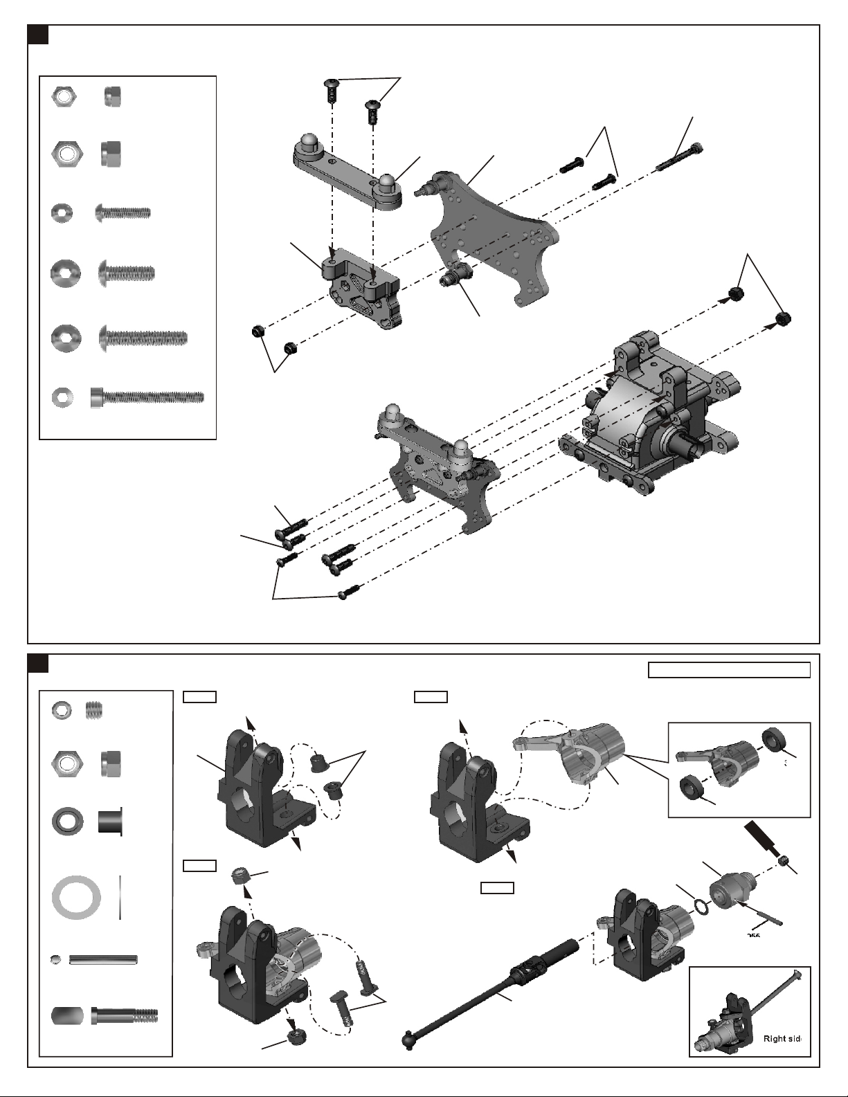
ASSEMBLY OF THE FRONT SHOCK STAY
4x12mm
35313
3mm
Nylon Nut
35314
4mm
Nylon Nut
94004
3x12mm
Hex Screw
94010
4x12mm
Hex Screw
94012
4x20mm
Hex Screw
90018
3x25mm
Screw
........x2
........x2
.......x4
.......x4
.......x2
.......x2
40117
3mm
4x20mm
40117
40531
40116
3x12mm
3x25mm
4mm
6
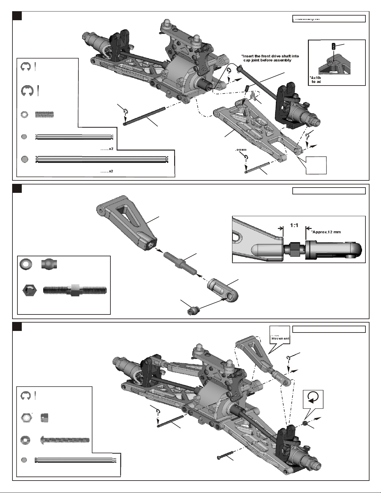
ASSEMBL OF THE KNUCKLE ARMSY
94034
4x4mm
Set Screw
35314
4mm
Nylon Nut
40527
Knukcle Arm
Bushing
40128
8x12x0.3mm
Washer
........x2
........x4
........x4
........x2
4x12mm
3x12mm
Step 1 Step 2
40536
Step 3
4mm
40527
Step 4
40520
Assembly for both right and left side
36053
Sc
Ce
r
ew
m
ent
30058
40128
8x12x0.3mm
36055
36053
4x4mm
36055
2.5x16.8mm
Pin
40528
King Screw
........x2
........x4
4mm
40528
40141
Right side
7
ASSEMBLY OF THE FRONT SUSPENSION ARMS
90020
2.5mm
E-Ring
........x2
*Insert the front drive shaft into
cap joint before assembly
4x10mm
Assembly for both right and left side
4x10mm
*4x10mm set screw is used
to adjust ride-height.
90021
3mm
E-Ring
36870
4x10mm
Set Screw
40546
3x42.7mm Arm Shaft
40524
4x73mm Arm Shaft
8
ASSEMBLY OF THE FRONT UPPER ARMS
36850
7mm Ball
........x2
........x2
........x2
3mm
........x2
........x2
40524
40139
36861
40140
2.5mm
36690
40140
40546
2.5mm
Ensure
Free
Movement
Assembly for both right and left side
1:1
*Approx.12 mm
36861
5X35MM
Turnbuckle
9
ASSEMBLY OF THE FRONT SUSPENSION ARMS
90020
2.5mm
E-Ring
35313
3mm
Nylon Nut
94008
3x25mm
Hex Screw
36170
3x44.3mm Arm Shaft
........x4
........x2
........x2
........x2
........x2
2.5mm
36850
36170
3x25mm
Ensure
Free
Movement
Assembly for both right and left side
2.5mm
Tighten
3mm
10
ASSEMBL OF THE FRONT STABILIZERY
9435
3x8mm
Set Screw
94006
3x18mm
Hex Screw
30403
6mm
Ball
11
ASSEMBL OF THE FRONT STABILIZERY
........x2
........x2
........x2
Makes two rods for left and right
hand-side.
30341
40029
40199
3x8mm
30403
Scre
Cem
Assembly for both right and left side
3x18mm
w
ent
3x3mm
94033
3x3mm
Set Screw
94003
3x10mm
Hex Screw
12
ASSEMBL OF THE SERVO SAVERY
........x2
........x4
40017
40017
3x10mm
40037
Step 1 Step 2
40032
*Do not tighten 40037
Hex Screw too tight.
40031
40019
40037
40035
3x3mm
w
tCeme
e
n
Scr
*Approx. 6mm
4x10mm
3x12mm
4x10mm
40030
*Take the plastic bushing from servo
saver plastic parts tree.
94004
3x12mm
Hex Screw
94009
4x10mm
Hex Screw
........x1
........x2
40031
40031
40031
40031
40031
40621
40018
40034
40036

13
ASSEMBL OF THE STEERING TIE-RODY
94041
3mm
Nylon Nut
94021
3x15mm
Flat Head
Hex Screw
94022
3x18mm
Flat Head
Hex Screw
........x2
........x2
........x2
3mm
Step 1 Step 2
40038
36700
40108
36700
40039
40038
3x15mm
40039
S
c ew
r
4x10mm
t
ew
en
cr
m
S
e
C
Cem nte
3x15mm
40039
94009
4x10mm
Hex Screw
14
ASSEMBL OF THE FRONT BUMPERY
3x10mm
94003
3x10mm
Hex Screw
........x2
1:1
*Approx. 45.8mm
Step 1 Step 2
40137
3x12mm
3x10mm
........x4
3x10mm
3x18mm
40137
40137
40137
3x12mm
3x12mm
40676
94004
3x12mm
Hex Screw
15
ASSEMBL OF THE REAR GEAR CASEY
40024
13x16x0.2mm
Shim
94011
4x16mm
Hex Screw
........x5
........x2
........x2
*Adjust the backlash with the shims.
40024
4x16mm
40017
Apply
Grease
36053
40017
36053
49012
40024

16
ASSEMBL OF THE REAR ARMS HOLDERY
94036
5x4mm
Set Screw
94003
3x10mm
Hex Screw
94009
4x12mm
Hex Screw
94030
4x45mm
Flat Head
Hex Screw
........x1
........x1
........x4
........x2
Step 1 Step 2
5x4mm
t
e
r w
c
e
S
em n
C
36730
40025
Tighten
40015
4x12mm
4x45mm
3x10mm
Do Not
Over Tighten
4x12mm
40027
17
ASSEMBL OF THE REAR SHOCK STAYY
Step 1 Step 2
40027
3x10mm
40145
Step 3
40531
40531
Screw
Cement
3x25mm
S
C t
3x25mm
c
e
r
men
e
w
94019
3x10mm
Flat Head
Hex Screw
94004
3x12mm
Hex Screw
90018
3x25mm
Cap Screw
........x1
........x2
........x2
3x12mm

18
ASSEMBL OF THE WING STAYY
Step 1 Step 2
40027
94042
4mm
Nylon Nut
94005
3x16mm
Hex Screw
94007
3x20mm
Hex Screw
........x2
........x2
........x4
Step 3
4x20mm
4x16mm
40027
40027
3x16mm
3x20mm
4x20mm
Step 4
40027
40027
3x20mm
3x16mm
4mm
4mm
4x20mm
94048
3x20mm
Cap Screw
94011
4x16mm
Hex Screw
94012
4x20mm
Hex Screw
19
ASSEMBL OF THE REAR WHEEL HUBSY
94036
5x4mm
Set Screw
36870
4x10mm
Set Screw
36055
2.5x16.8mm
Pin
........x2
........x2
........x2
........x1
........x3
........x3
40018
Step 1 Step 2
36053
36055
8x12x0.3mm
5x4mm
30058
2.5mm
3x20mm
4x10mm
Assembly for both right and left side
40140
2.5mm
*4x10mm set screw is used
to adjust ride-height.
4x16mm
4x10mm
Ensure
Free
Movement
40128
8x12x0.3mm
Washer
........x2
40522
40540
40525
40540

20
ASSEMBL OF THE REAR SUSPENSION ARMSY
Assembly for both right and left side
3mm
90021
3mm
E-Ring
40524
4x73mm Arm Shaft
21
ASSEMBL OF THE REAR SUSPENSION ARMSY
94041
3mm
Nylon Nut
94006
3x18mm
Hex Screw
94008
3x25mm
Hex Screw
........x4
........x2
........x4
........x2
........x2
3mm
40524
Step 1 Step 2
36850
40540
1:1
*Approx. 35mm
36880
40540
36850
3x18mm
40140
40142
(114mm)
Ensure
Free
Movement
Assembly for both right and left side
3mm
3mm
22
ASSEMBL OF THE REAR STABILIZERY
Step 1 Step 2
30341
40029
3x8mm
40199
30403
94033
3x3mm
Set Screw
94035
3x8mm
Set Screw
94003
3x10mm
Hex Screw
........x2
........x2
........x4
3x16mm
40017
3x25mm
3x3mm
3x3mm
94005
3x16mm
Hex Screw
........x2
3x10mm
Ensure
Free
Movement
40019

23
ASSEMBL OF THE BRAKE AND CENTER DIFF. MOUNTY
Step 1
40591
Step 4 Step 5
40676
Step 2
40040
40662
3x10mm
Step 3
40040
36660
3x12mm
3x3mm
40041
40040
40665
3x3mm
30171
40665
3x12mm
Step 7Step 6
40031
30171
94033
3x3mm
Set Screw
94003
3x10mm
Hex Screw
94004
3x12mm
Hex Screw
........x2
........x2
........x6

24
ASSEMBL OF THE RADIO TRAYY
3x10mm
94040
3x8mm Washer
94003
3x10mm
Hex Screw
........x8
........x6
40138
40143
Step 2 Step 3Step 1
3x20mm
3x8mm
40676
3x8mm
3x12mm
3x8mm
40031
3x10mm
40117
40541
3x25mm
3x8mm
40676
94004
3x12mm
Hex Screw
94007
3x20mm
Hex Screw
94008
3x25mm
Hex Screw
25
ASSEMBL OF THE RECEIVER BOXY
Step 1
10282
2x8mm
........x4
........x2
........x2
Switch
40541
40541
Step 2
37410
40541
37410
40031
30560
40541
40855
Battery
*Use the screw provide
with your switch.
Screw
40541
........x42x8mm
Receiver

26
ASSEMBL OF THE RADIO TRAY INTO RECEIVER BOXY
94004
3x12mm
Hex Screw
27
ASSEMBL OF THE FRONT GEAR CASE ONTO CHASSISY
3x12mm
........x2
4x10mm
4x12mm
4x16mm
4x10mm
Flat Head
Hex Screw
94026
4x12mm
Flat Head
Hex Screw
94027
4x16mm
Flat Head
Hex Screw
28
ASSEMBL OF THE REAR GEAR CASE ONTO CHASSISY
40133
........x2
........x2
........x4
4x12mm
4x16mm
94026
4x12mm
Flat Head
Hex Screw
94027
4x16mm
Flat Head
Hex Screw
........x2
........x4

29
ASSEMBL OF THE CENTER DIFF. ONTO CHASSISY
40136
(104mm)
4x10mm
Flat Head
Hex Screw
30
ASSEMBL OF THE RADIO TRAY ONTO CHASSISY
........x4
4x10mm
Radio Tray assembly
40136
(120mm)
*Insert the drive shaft into
the cap joint before assembly
center diff. onto chassis.
94019
3x10mm
Flat Head
Hex Screw
31
ASSEMBL OF THE FUEL TANK ONTO CHASSISY
94040
3x8mm Washer
94019
3x10mm
Flat Head
Hex Screw
94004
3x12mm
Hex Screw
........x8
Pressure Nipple
40109
........x2
........x2
........x2
3x12mm
3x8mm
40138
3x12mm
3x8mm
Pressure Nipple
3x10mm
Step 2Step 1
Do Not
Over Tighten
3x10mm

32
ASSEMBL OF THE CLUTCH AND ENGINE MOUNTY
Step 1 Step 2
*Fit the flywheel using a pair of the
plIer and cross wrench.
10098
* Only use this 10091 pilot shaft for threaded crank
shaft engine.
Sc
Ce n
w
re
e t
m
10040
Sc
Cem nt
10040
10091
10010
re
w
e
*Place the clutch shoes with the clutch
springs over the 3 pins of the flywheel.
*Using a phillips screw driver or needle
nose pliers and bend the small end in
10330
the clutch spring behind the pilot shaft
10102 than press down.
Step 3 Step 4
10102
3x16mm
Threaded
Crank Shaft
10330
34110
5x9x0.3mm
3x10mm
Cap Screw
........x1
3x8mm
10399
3x16mm
Cap Screw
33
ASSEMBL OF THE MANIFOLD AND MUFFLERY
........x4
3x10mm
Step 1 Step 2
31995
40674
10120
97500
14
31994
10185
ZIP TIES

34
ASSEMBL OF THE ENGINE ONTO CHASSISY
Note book Paper.
*Use note book paper to set gear backlash between
spur gear and clutch bell gear, applying pressure
while tightening the engine.
*If the space is not correct the spur gear will
be damaged.
94034
4x4mm
Set Screw
4x10mm
Flat Head
Hex Screw
........x2
........x1
3x12mm
4x4mm
40050
4x4mm
94004
3x12mm
Hex Screw
10114
5mm
Engine Mount
Screw
35
ASSEMBL OF THE FUEL TUBEY
........x2
40051
10114
4x10mm
........x4
Connect to carbulater.
10177
Connect to pressure nipple.
Connect to fuel tank nipple.
Connect to fuel nipple.
10177
36
ASSEMBL OF THE STEERING RODY
94003
3x10mm
Hex Screw
94004
3x12mm
Hex Screw
........x1
........x1
30661
30403
3x10mm
10759
30403
30401
38281
Use the screw
provided with
your servo.
3x12mm
1:1
*Approx. 28.5mm

37
ASSEMBL OF THE THROTTLE LINKAGEY
3x3mm
Step 1 Step 2
94033
3x3mm
Set Screw
2mm
Nut
2.5mm
Nylon Nut
2x8mm
Screw
94003
3x10mm
Hex Screw
........x4
........x2
........x1
........x2
........x1
3x3mm
10300
Step 3
Ce nt
me
2mm
30802
r
eSc
w
40664
3x3mm
10300
30531
2x8mm
30661
Cut off the servo saver as shown.
30802
Step 4
2.5mm
30802
30802
30802
2.5x18mm
Ensure
Free
Movement
40664
40617
Adjust the high
with3x6,4x1mm
washer
36140
3x3mm
36140
40664
2.5x18mm
Screw
38
ASSEMBL OF THE THROTTLE LINKAGEY
........x1
Use the screw
provided with
your servo.
3x10mm
3x3mm
10300
94033
3x3mm
Set Screw
10759
........x2

39
ADJUSTING THE ENGINE CONTROL LINKAGES
(Neutral)
Approx. 0.5mm
Turn on the Transmitter then Receiver and set the
Engine Control Servo Trim to the neutral position.
Adjust the idling adjusting screw on the Carburetor
to be open approx. 1mm gap.
Adjust both of the 10300 Engine Control and Brake linkage
accordingly.
Adjust the Engine while it is NOT RUNNING.
40
ASSEMBLY OF THE AIR FILTER
Step 1 Step 2
3x8mm
40127
40128
10300
Approx. 1mm gap
Idling Adjusting Screw
.
*Apply filter oil to the
foam before use.
(Throttle High)
Adjust the Servo-Horn mounting position for the
Carburetor to be full open.
Change the pivot mounting position on the servo
horn in case the Carburetor is not opening fully or
if it is opening excessively. Or if available on the
Transmitter, adjust the Throttle high end point.
ZIP TIES
Carburetor is
Opening fully
ZIP TIES
(Brake)
Spring Compress
10300
36140 Alum. Adjust Nut
Adjust 10300 so the brakes work smoothly.
If the brakes apply too much or not enough,
adjust 36140 accordingly. Or if available on the
Transmitter, adjust the High-End Brake
adjustment.
Adjust 36140 to Change the front or Rear Brake.
40128
94002
3x8mm
Hex Screw
41
ASSEMBLY OF THE FRONT SHOCK
Builds two front shocks.
2.6x5mm
Washer
40060
2.5mm
Nylon Nut
40090
3.5mm
O-Ring
40090
1mm
Washer
40090
2mm
Washer
........x4
........x2
........x4
........x2
........x2
........x1
Step 1
30403
41008
40090
40090
41019
41003
40127
40643
(Long)
40090
40090
40129
Fit the o-ring into groove
before assembly.
41007
41006
40054
(Short/Front)
2.6x5mm
41011
(1.4mmx6)
2.6x5mm
Step 2
1. Pull down piston and pour oil into shock cylinder.
2. To remove air bubbles by slowly moving piston up
and down.
3. Pull down piston, attach pressure top
and shock oil overflow with tissue
paper.
fill the shocks
with oil #50WT.
41013
41005
CORRECT SHOCK ASSEMBLY
56.7mm
28mm
OK
Carefully screw the shock
shaft into the bottom of the
plastic ball end untill the
distance between the ball end
and the shock body is 28mm
for the front .
N.B. Do not over tighten as the
plastic will strip.
30403
6mm
Ball End
........x2
40060
Do Not
Over Tighten
0 20
30
4010

42
ASSEMBL OF THE REAR SHOCKSY
Builds two rear shocks.
2.6x5mm
Washer
40060
2.5mm
Nylon Nut
40090
3.5mm
O-Ring
40090
1mm
Washer
40090
2mm
Washer
30403
6mm
Ball End
........x4
........x2
........x4
........x2
........x2
........x2
Step 1
30403
41004
41008
40090
40090
41019
40643
(Long)
40090
40090
Fit the o-ring into groove
before assembly.
41007
41006
40055
(Long/Rear)
2.6x5mm
41011
(1.4mmx6)
2.6x5mm
40060
Do Not
Over Tighten
Step 2
1. Pull down piston and pour oil into shock cylinder.
2. To remove air bubbles by slowly moving piston up
and down.
3. Pull down piston, attach pressure top
and shock oil overflow with tissue
paper.
fill the shocks
with oil .#50
41013
41005
0 20
CORRECT SHOCK ASSEMBLY
65.2mm
37.5mm
OK
Carefully screw the shock
shaft into the bottom of the
plastic ball end untill the
distance between the ball end
and the shock body is 37.5mm
for the rear .
N.B. Do not over tighten as the
plastic will strip.
30
4010
43
ASSEMBL OF THE FRONT SHOCK SPRINGSY
40058
m
u m
Ct7
45
ASSEMBL OF THE FRONT SHOCK ABSORBERY
Assembly for both right and left side
41028
41008
44
ASSEMBL OF THE REAR SHOCK SPRINGSY
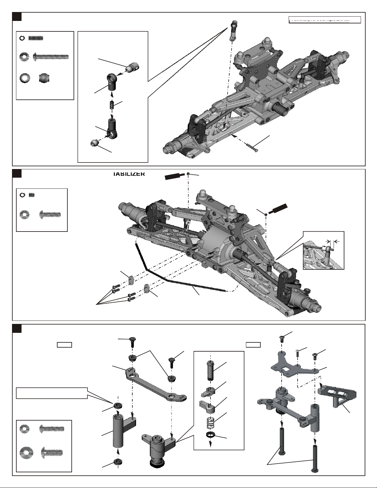
40058
41023
41008
94041
3mm
Nylon Nut
94040
3x8mm
Washer
94007
3x20mm
Hex Screw
........x2
........x2
........x2
3mm
3x8mm
3x20mm

46
ASSEMBL OF THE REAR SHOCK ABSORBERY
Assembly for both right and left side
94041
3mm
Nylon Nut
94040
3x8mm
Washer
94007
3x20mm
Hex Screw
47
ASSEMBL OF THE TIRES AND WHEELSY
........x2
........x2
........x2
3mm
3x8mm
3x20mm
Step 1
80022
48
ASSEMBL TIRE ONTO FRONT KNUCKLE AND REAR HUBY
81106
Step 2
86106
Step 3
Apply instant glue into the groove of the wheel.
INST
GL
N
UE
TA
Tire and wheel assembly
40550

49
ASSEMBL OF THE WINGY
3x12mm
20
15
*Check the hole spacing on the underside.
3mm
Nylon Nut
3x12mm
Hex Screw
50
MOUNTING BODY
0
5
10
5
........x294041
........x294004
20
10
15
2525
40673RW
31159
40027
40083
3mm
51
STARTING OF THE ENGINE
How to start the engine:
1.Connect the Starter to the truck
*Connect the Starter control box to the connector
located in the rear shock stay mount.
*Caution : Before starting the engine ,review the
important-read this before running and operate
your model safety.
2.Start the engine
*With one hand ,hold the throttle half open using
the throttle trigger on the transmitter. With your
other hand ,press the red button on the Starter.
If the engine does not start ,release the red
button and try again in 5 sec. Interval.
*Follow the engine manufacturer instruction
manuals regarding engine set-up, carburetor
and maintenance.
7.2V Battery
(Not included)
Electric Starter
Electric Starter

SETTING GUIDE
FRONT CAMBER ANGLE SETTING REAR CAMBER ANGLE SETTING
Turnbuckle
+
Place the model car on flat surface. Raise the chassis to it's maximum clearance
before the wheels leave the ground.
Adjust the length of the front and rear upper arms so that the wheels are right angle to the
ground.
The camber angle adjustment can be moving the turnbuckle rod on the upper arms,
clockwise or anti-clockwise.
(We suggest use zero degree for the front and 2 degree for the rear.) negative
-
FRONT TOE-IN AND TOE-OUT SETTING
NEUTRAL POSITION
TOE-OUT
TOE-IN
-
+
TOE-OUT
+
-
NegativeNegative PositivePositive
FRONT SHOCK ANGLE SETTING
Soft
1
4
5
2
3
6
Turnbuckle
Firm
-
+
Adjust the length of front steering rod to change the
toe angle.
Making the tie rod longer will make the front tires
become toe-in.
Response will be slower and will over steer.
Making the tie rod shorter will make the front tires
become toe-out.
Response will be quicker and will under steer.
REAR TOE-IN SETTING
By change the rear toe-in block can be change
rear toe-in.
Steering Rod
Firm front suspension, less steering.
Soft front suspension, more steering.
REAR SHOCK ANGLE SETTING
Firm rear suspension, over steering.
Soft rear suspension, under steering.
REAR WHEELBASE
367.5mm 370mm365mm
0
Soft
1
4
5
2
Soft
6
3
Soft
Firm
12
Firm
12
Firm
1
1 Degree 2 Degree 3 Degree
2
3
Adjust the wheelbase by using the spacers on either side of the rear uprights (at the bottom pin).
IMPORTANT! Make equal adjustments on both left and right sides of the car.
Shorter wheelbase
less spacers in front of the rear upright.
- increases rearward weight transfer during acceleration.
- increases on-power traction.
- quicker off-power steering into corners.
- slight tendency to push on-power at corner exit.
- increases steering response.
- better on tighter, more technical tracks.
Longer wheelbase
more spacers in front of the rear upright.
- decreases off-power steering into sharp corners.
- increases stability.
- slower initial steering reaction (off-power).
- improves on-power steering at corner exit.
- better handling over bumps and ruts.
- better on more open tracks with high-speed corners.


MUTILATOR V3
SETTUP SHEET
DRIVER:
DATE:
TRACK:
SIZE:
OPEN
MEDUIM
TIGHT
TRACTION:
HIGH
MEDIUM
LOW
SURFACE:
SMOOTH
MEDIUM
BUMPY
FRONT SUSPENSION
TOE ANGLE
RIDHIEIGHT
CAMBER
SWAY BAR
OIL:
PISTON:
SPRING:
IN:
OUT:
mm
POS:
NEG:
2.5mm
OTHER
FRONT SHOCHS
W
STANDARD
DRLLRD
SOFT
MEDUIM
HARD
OTHER
mm x 1
mm x 2
WHEEL
NOTES:
1
2
3
4
5
6
1
2
3
1
2
REBOUND STOP:
A
B
mm
REAR SUSPENSION
REAR TOR-IN PLATE:
1
2
3
RIDHIEIGHT
CAMBER
SWAY BAR
REAR SHOCHS
OIL:
PISTON:
SPRING:
1 Degree
2 Degree
3 Degree
POS:
NEG:
2.5mm
OTHER
W
STANDARD
DRLLRD
SOFT
MEDUIM
HARD
mm
OTHER
mm x 1
mm x 2
WHEEL
NOTES:
1
2
3
4
5
6
1
3
4
5
2
1 2
1 2
REBOUND STOP:
WIN POSITION
A
B
mm
DIFF OIL TORSEN DIFF
ENGINE
FRONT: FRONT:
CENTER: CENTER:
REAR: REAR:
TYPE:
GASKET:
mm
PLUG:
MUFFLER:
FUEL:
TIRES
CLUTCH
TYPE: TYPE:
FRONT
INSERT: INSERT:
CLUTCH BELL
13T
14T
15T
CLUTCH SHOES
REAR
3 SHOE
4 SHOE


OFNA DESCRI PTION RETAIL OFNA DESCRIPTION RETAIL
10010 CLUTCH SHOES, BLACK, 3 SHOES 13.95 40065 BALL ENDS, PLASTIC, REAR UPPER 4.95
10011 SHOES,ALUM BLUE-1.8g W /SPRING 24.95 40083 W IN G , 9.5 , W H ITE 15.95
10012 SHOES,ALUM PURPLE-2.0gW /SPRING 24.95 40090 SEALS,SHOCK REBU ILD, 9.5 X-1 7.95
10013 SHOES,ALUM SILVER-1.7gW /SPRING 29.95 40093 CAPS, SHOCK, HARD COATED LONG 15.95
10040 3 P IN FLYW H EEL, .21 CORN TYPE 14.95 40098 PISTONS, SHOCK, BLACK 9.5 & X1 5.95
10069 RED SEAL, SILICONE ROUND, 2PCS 6.95 40108 TURNBUCKLE, 4x56mm, 9.5V PAIR 7.95
10073 PIPE,INLINE,OFNA-095, POLISHED 79.95 40109 TAN K,FUEL,150cc VIO LATO R,X1CR T 13.95
10098 CLUTCH NUT, SG SHAFT 4.95 40116 SHOCK TOW ER FR/RR NEW BLAZER 9.95
10101 SPRINGS,CLUTCH,GOLD 1.1M 3PCS 4.95 40117 BLAZER TRUCK BODY MOUNT NEW 10.95
10114 FLAT HEAD ENGINE MOUNT SCREW S 7.95 40127 AIR FILTER SET, X-1 9.95
10120 SPRING, MANIFOLD, R.PORT .21 4.95 40128 FO AM, REPLACEMEN T FOR 40127 5.95
10177 FUEL LINE 3FT. G RAY/BLACK 1.95 40129 CONNECTOR, RUBBER FOR 40127 5.95
10185 SILIC ONE JOINT TUBE, SPL, BLACK 5.95 40133 C HAS SIS , M UTILAT OR 6061 3mm 79.95
10282 SW ITC H COVER, SILICONE BLACK 3.95 40134 SPUR, GEAR STEEL 62T MTL. 34.95
10300 ALUM . STOPPER KIT, 6 PCS. 4.95 40136 CENTER DRIVE SHAFT 104,120mm 16.95
10399 CLUTCH BELL W /BEARINGS, 13T 19.95 40137 BUM PER MUTILATOR 12.95
10765 SERVO HORNS, HD NYLON,BLUE SET 8.95 40138 RADIO TRAY POST, PLASTIC 4.95
30051 W HEEL HUB 17x6mm, BLUE PAIR 10.95 40139 ARM, FRONT UPPER MUTILATOR PRO 6.95
30058 W HEEL HUB EXTENSIO NS, 15mm 4PC 19.95 40140 ARM, FR & RR LOWER MTL PRO 12.95
30171 LEVER, BRAKE 1.95 40141 UNIVERSAL FRO NT MUTILATOR PRO 39.95
30341 BALL END W ITH COLLAR, 6mm 3.95 40142 DRIVE SHAFT REAR 114mm MTL PRO 12.95
30401 STEER ING EN DS, PLASTIC 6 PCS. 2.95 40143 RADIO TRAY MTL PRO H.C. 12.95
30402 3x30m m TIE RO D 2.95 40145 SHOCK TOW ER RR MTL AUTOSTART 14.95
30403 6m m BALL, ST EEL (NO COLLAR) 4.95 40199 STEERING BALL END,PLASTIC , 6mm 7.95
30530 THROTTLE JOINT KIT, NYLON END 3.95 40513 DIFF. GE AR (sm all & large)ALU M 16.95
30531 SPRING, THROTTLE LINKAG E 2.95 40520 KNUCKLE ARM, L & R 19.95
30560 ANT TUBE AND MOUNT 2.95 40525 SHAFT 3x48.1m m DM UPPER FRONT 6.95
30661 SERVO HORN HEAVY DUTY BLACK 4.95 40526 W HEEL HUB 5m m 11.95
30776 W ASHE R, 4x10x0.2m m 4PCS. 1.95 40527 KNUCKLE ARM BUSHING 4.95
30800 LINKAGE, BRAKE/THRO TTLE (98) 6.95 40528 KING PIN SCREW 1.95
30802 LINKAGE, 2 THROTTLE LINKAG E 7.95 40531 SHOC K BALL POST/O NE-PIECE/TOP 9.95
31994 PIPE, 9.5mm RTR POLISED 54.95 40536 FRONT C HUB 11.95
31995 MANIFOLD, SILVER MTL AUTOSTAR T 25.95 40540 REAR UP RHT & UPR ARM, BUMPER 9.95
34110 BEARING, 5x10, 2 PCS 6.95 40541 REC EIVER BOX, NEW TYPE 14.95
36053 BEARING, 8x16m m, PAIR 12.95 40546 FRONT ARM SHAFT 3x42.7mm 11.95
36055 PIN, 2.5x17mm , HEX HUBS, 4PCS 3.95 40550 W HEEL NUT 5mm 4.95
36081 REAR UP-RIGHT (8mm BEARING) PR 12.95 40556 ALUM. SHOCK SPRING ADJ. H.C. 21.95
36082 REAR AXLES, 8mm PAIR 10.95 40591 BRAKE DISK, FIBER X1-C R/CRT 14.95
36170 ARM PINS, 3mm 4PCS LX1 7.95 40617 W ASHER , PLASTIC, BLAC K 8PCS. 3.95
36660 BRAKE PAD, 4PCS. 3.95 40642 ANTENNA PIPE FIXING NUT 2.95
36690 UPPER BALL END, 7mm 6PCS 6.95 40662 CENTER DIFF. MOUNT POST 19.95
36700 STEER ING BALL END, 7mm , 8PCS. 6.95 40664 BRAKE ROD, 2x68mm 3.95
36730 JOINTS CAP, 6m m, 2PCS. 11.95 40665 BRAKE CAM 8.95
36850 7m m BALL, 6 PC S. 3.95 40673R W BODY, TRUGGY MUTILATOR RED/W H 69.95
36860 5x40mm TURNBUCKLES, 2 PCS. SIL 6.95 40674 ENGINE MOUNT (Tall) CR & CRT 18.95
36861 5x40mm TURNBUCKLES, 2 PCS BLK 6.95 40676 BODY PO ST AND SERVO MOUNT 9.95
36880 5x60mm TURNBUCKLES 6.95 40855 ANT. TUBE FIXING NUT (BROW N) 2.95
37410 BO DY CLIPS, 10 PCS. SMALL 3.95 41001 SHOCK BIG BORE FRO NT 16MM PAIR 79.95
38281 TURNBUCKLES, 3X40MM, 2PCS 5.95 41002 SHOCK BIG BORE REAR 16MM PAIR 79.95
38313 CONE, TAPER ED 7mm , SG 2.95 41003 SHOCK BODY FRONT 16MM PAIR 29.95
40003 CASE, DIFF, 1 PC 9.95 41004 SHOCK BODY REAR 16M M PAIR 29.95
40005 CAP JOINT, BRAKE, 2PCS 13.95 41005 SHO CK CAP 16MM 4PCS. 22.95
40006 CAP JOINT, FNT&RR DIFF, 2PCS. 13.95 41006 SHOC K SPRING ADJ. 16MM 4PCS. 14.95
40009 SEAL, P-6 O-RING, DIFF, 2PCS 2.95 41007 O -RIN G 19x1.5MM 16MM 4PC S. 4.95
40010 P IN , 2 .5X1 3 .8M M , D IFF , 2 P C S 2.95 41008 PLASTIC SH OCK PARTS 16MM SET 12.95
40011 G ASKET, DIFF 3PCS 3.95 41009 CAP SCREW S 3X28M M 4PCS. 2.95
40015 FRONT HOLDER, LOW ER ARMS 5PCS 14.95 41010 SHO CK BALL END PO ST LONG 4PCS 11.95
40017 M AIN G EAR BOX, FRONT&REAR, 1PC 18.95 41011 SHO CK PISTON 16MM 8PCS. 10.95
40018 BRACE, CENTER, NYLO N, 9.5 KIT 7.95 41012 REPAIR KIT FO R 16MM SHOCK 9.95
40019 ANTI-ROLL KIT (FRONT/REAR) 13.95 41013 PRESSURE TOP ORANGE 16MM 4PCS. 7.95
40022 FRONT, LOW ER ALUM. HOLDER 11.95 41014 SPRING 16MM SUPER SOFT YEL SET 17.95
40023 SHAFTS, LOW ER ARM S, 4MM , 4PCS. 17.95 41015 SPRING 16MM SOFT W HITE SET 17.95
40024 S H IM , 13 X 16 X O .2 M M , D IF F G E A R ,4 2.95 41016 SPRING 16MM BUGGY SILVER SET 17.95
40025 REAR, LOW ER ARM ALUM. HOLDER 11.95 41017 SPRING 16MM HARD GRAY SET 17.95
40027 W ING MOUNT SUPPORT SET 19.95 41018 SPRING 16MM TRU GGY BLUE SET 17.95
40028 DOG BONES, 93MM PAIR LX1 19.95 41019 O-RING 1OMMx1MM FOR 16MM SHOCK 2.95
40029 BALL ENDS, PLASTIC, ANTI-ROLL 3.95 41020 SHO CK BALL END POST L.W . LONG 14.95
40030 FRONT PLATE, ALUM. H.C. 8.95 41021 SP RING .52 REAR 16M M YELLOW 9.95
40031 SERVO SAVER HORN 15.95 41022 SPRING .58 REAR 16MM W HITE 9.95
34313 MUTILATO R AUTOSTART PARTS LIST
40032 PLATE, SERVO SAVER ,SLIDER H .C. 10.95 41023 SPRING .59 REAR 16MM BLUE 9.95
40033 SPRING, SERVO SAVER 3.95 41024 SPRING .60 REAR 16MM SILVER 9.95
40034 ALUM . RING, SERVO SAVER ADJ.RI 5.95 41025 SPRING .64 REAR 16M M GRAY 9.95
40035 AXLE TUBE, SER VO SAVER 35.95 41026 SPRING .66 F RONT 16M M Y ELLOW 9.95
40036 AXLE POSTS, SERVO SAVER 5.95 41027 SPRING .70 FRONT 16MM W HITE 9.95
40037 SCREW S, SERVO PLATE 5.95 41028 SPRING .71 FRONT 16M M B LUE 9.95
40038 BALLS, 7MM 4PCS. 9.95 41029 SPRING .74 FR ON T 16MM SILVER 9.95
40039 CONE, ALUM. 3MM, 4PCS. 3.95 41030 SPRING .88 FRONT 16MM GRAY 9.95
40040 CENTER DIFF MOUNT 4.95 50110 M OTOR, AUTO STAR T REPLACEMENT 9.95
40041 CENTER, ALUM . TOP PLATE, H.C . 8.95 50111 W IRE SET FOR AUT0 START 5.95
40050 PO ST, PIPE HOLDER 6.95 50114 GEAR ASLB W /O M OTOR MTL, ULTRA 33.95
40051 W IRE, PIPE MOUN T 4.95 52226 FORC E .28 AUTO START SYSTEM 299.95
40054 SHAFTS,3.5m FRONT SHOCKS, 2PCS 7.95 49012 GEAR, 13T PINION 7.95
40055 SHAFTS,3.5m REAR SHOCKS, 2PCS 7.95 49032 GEAR, BEVEL, 43 TOOTH 29.95
40057 ADJUSTERS, SPRING, BLUE, 4PCS 20.95 80022 TIRES, X LPR TRUGGY w/INSERTS 30.95
40058 COVERS, SH OCK SHAFTS, SILICONE 9.95 86106 W HEELS ,3.7 1/2O FFSET LPR W HT4P 28.95
40059 SEALS, 14.7mm O-RING, 4PCS 4.95 86107 W H EELS,3.7 1/2OFFSET LP R YEL4P 28.95
40060 NYLOK NUT, 2.5, PISTON NUT, 4 4.95 86108 W HEELS,3.7 1/2OFFSET LPR BLK4P 28.95
86109 W H EELS,3.7 1/2OFF SET LPR ORG4P 28.95


OWNER’S REGISTRATION CARD
OFNA Racing congratulates you on your purchase of our fine OFNA Product. With proper maintenance and handling this kit will provide many hours of enjoyment.
The registration card should be filled out and mailed to OFNA Racing within 10 days of purchase date.
In the event that the kit is incomplete or component parts are broken due to error in manufacturer, contact your
dealer from which you purchased the kit for replacement part or call OFNA at (949) 586-2910 for your nearest dealer
location. Other items such as radio and engine other covered by individual warranties.
IMPORTANT!
Please print or type, filling in the information listed below and mail immediately
MAIL TO:
OFNA RACING
7 VANDERBILT
IRVINE, CA. 92618
TEL: (949) 586-2910
Write in Your Model Name and Part Number
REGISTRATION CARD
RACER’S NAME TEL:( )
ADDRESS
CITY STATE ZIP
DEALER’S NAME TEL: ( )
ADDRESS
CITY STATE ZIP
OFNA
7 Vanderbilt
Irvine, Ca. 92618
 Loading...