


OCEANIC®
Pro Plus 2
dive computer
operating manual
LIMITEDTWO-YEARWARRANTY
For details, refer to the Product Warranty Registration Card provided.
COPYRIGHTNOTICE
This operating manual is copyrighted, all rights are reserved. It may not, in whole or in part, be copied, photocopied, reproduced, translated, or reduced to any electronic medium or machine readable form without prior consent in writing from Oceanic / 2002 Design.
Pro Plus 2 Operating Manual, Doc. No. 12-2328
© 2002 Design 2002
San Leandro, Ca. USA 94577
TRADEMARKNOTICE
Oceanic, the Oceanic logo, Pro Plus 2, the Pro Plus 2 logo, Smart Glo, OceanGlo, Graphic Diver Interface, Tissue Loading Bar Graph, Pre Dive Planning Sequence, Variable Ascent Rate Indicator, Set Point, Control Console, Turn Gas Alarm, and OceanLog are all registered and unregistered trademarks of Oceanic. All rights are reserved.
PATENTNOTICE
U.S. Patents have been issued, or applied for, to protect the following design features:
Dive Time Remaining (U.S. Patent no. 4,586,136), Data Sensing and Processing Device (U.S. Patent no. 4,882,678), Air Time Remaining (U.S. Patent no. 4,586,136), and Variable Ascent Rate Indicator (U.S. Patent no. 5,156,055). User Setable Display (U.S. Patent no. 5,845,235) is owned by Suunto Oy (Finland).
DECOMPRESSIONMODEL
The programs within the Pro Plus 2 simulate the absorption of nitrogen into the body by using a mathematical model. This model is merely a way to apply a limited set of data to a large range of experiences. The Pro Plus 2 dive computer model is based upon the latest research and experiments in decompression theory. Still, using the Pro Plus 2, just as using the U.S. Navy (or other) No Decompression Tables, is no guarantee of avoiding decompression sickness, i.e. “the bends.” Every diver’s physiology is different, and can even vary from day to day. No machine can predict how your body will react to a particular dive profile.
2
|
CONTENTS |
LIMITED TWO-YEAR WARRANTY ................................................................................................................................ |
2 |
NOTICES ...................................................................................................................................................................... |
2 |
DECOMPRESSION MODEL ......................................................................................................................................... |
2 |
FEATURES AND DISPLAYS .............................................................................................. |
7 |
INTERACTIVE CONTROL CONSOLE .......................................................................................................................... |
8 |
BAR GRAPHS .............................................................................................................................................................. |
9 |
Tissue Loading Bar Graph (TLBG) ............................................................................................................................. |
9 |
Oxygen Bar Graph (O2BG) ...................................................................................................................................... |
10 |
VariableAscent Rate Indicator (VARI) ....................................................................................................................... |
10 |
Air Time Remaining Bar Graph (ATRBG) .................................................................................................................. |
11 |
DIVE TIME REMAINING .............................................................................................................................................. |
11 |
ALPHA / NUMERIC DISPLAYS ................................................................................................................................... |
12 |
Cylinder Pressure ................................................................................................................................................... |
12 |
Depth Displays ....................................................................................................................................................... |
12 |
Time and Date Displays .......................................................................................................................................... |
13 |
Temperature Display ............................................................................................................................................... |
13 |
AUDIBLE ALARM ....................................................................................................................................................... |
14 |
LED Warning Light .................................................................................................................................................. |
14 |
SMARTGLO BACKLIGHT ........................................................................................................................................... |
16 |
POWER SUPPLY ........................................................................................................................................................ |
16 |
Battery Consumption Indicator .................................................................................................................................. |
16 |
Low Battery Condition ............................................................................................................................................. |
17 |
FO2 MODE .................................................................................................................................................................. |
18 |
FO2 50% Default .................................................................................................................................................... |
19 |
3
CONTENTS (continued) |
|
ACTIVATION AND SETUP ............................................................................................... |
21 |
ACTIVATION ............................................................................................................................................................... |
22 |
SURFACE MODE ........................................................................................................................................................ |
23 |
Accessing Other Modes .......................................................................................................................................... |
23 |
SET MODES ............................................................................................................................................................... |
24 |
ENTERING SETTINGS -SET MODE #1 ................................................................................................................... |
25 |
ENTERING SETTINGS -SET MODE #2 ................................................................................................................... |
29 |
PLAN AND DIVE MODES ................................................................................................ |
45 |
PRE DIVE PLANNING SEQUENCETM ....................................................................................................................... |
46 |
TISSUE LOADING BAR GRAPH ................................................................................................................................. |
48 |
OXYGENACCUMULATION BAR GRAPH ................................................................................................................... |
49 |
VARIABLEASCENT RATE INDICATOR ..................................................................................................................... |
49 |
AIR TIME REMAINING BAR GRAPH BAR GRAPH ..................................................................................................... |
50 |
CONTROL OF DISPLAYS ........................................................................................................................................... |
50 |
NO DECOMPRESSION DIVE MODE .......................................................................................................................... |
51 |
DECOMPRESSION DIVE MODE ................................................................................................................................ |
54 |
VIOLATION MODES .................................................................................................................................................... |
57 |
Conditional Violation Mode ...................................................................................................................................... |
57 |
Delayed Violation Modes ......................................................................................................................................... |
59 |
Immediate Violation Mode and Gauge Mode ............................................................................................................ |
60 |
HIGH PO2 DIVE MODE ............................................................................................................................................... |
62 |
HIGH OXYGENACCUMULATION ............................................................................................................................... |
63 |
USER SET DIGITAL GAUGE MODE ........................................................................................................................... |
64 |
UNEXPECTED LOSS OF DISPLAYED INFORMATION .............................................................................................. |
64 |
4

CONTENTS (continued) |
|
POST DIVE MODES ........................................................................................................ |
65 |
POST DIVE SURFACE MODE .................................................................................................................................... |
66 |
TRANSITION PERIOD ................................................................................................................................................ |
66 |
AFTER THE TRANSITION PERIOD (THE FIRST 2 HOURS) ....................................................................................... |
68 |
To activate the Backlight - ........................................................................................................................................ |
68 |
To access the Pre Dive Planning Sequence - ............................................................................................................ |
68 |
To access the Time to Fly Countdown ....................................................................................................................... |
69 |
To access the Time to Desaturate Countdown ........................................................................................................... |
69 |
Log Mode ............................................................................................................................................................... |
70 |
AFTER THE FIRST 2 HOURS ..................................................................................................................................... |
72 |
WET CONTACTS ........................................................................................................................................................ |
73 |
DOWNLOADING DATATOAPC ................................................................................................................................. |
74 |
SIMULATOR (DEMO) MODE ............................................................................................ |
75 |
GENERAL ........................................................................................................................ |
83 |
CARE AND CLEANING .............................................................................................................................................. |
84 |
INSPECTIONS AND SERVICE ................................................................................................................................... |
84 |
BATTERY REPLACEMENT ........................................................................................................................................ |
86 |
SPECIFICATIONS ....................................................................................................................................................... |
90 |
OCEANIC WORLD WIDE ............................................................................................................................................ |
96 |
SERVICE RECORD .................................................................................................................................................... |
97 |
RESET PROCEDURE ................................................................................................................................................ |
99 |
Payspecialattentiontoitemsmarked |
|
withthisWarningsymbol. |
|
WARNING: Prior to diving with the Pro Plus 2, you must also read and |
|
understandtheOceanicDiveComputerSafetyandReferenceManual. |
|
5

|
m |
|
|
|
|
|
|
|
|
n |
|
|
|
|
|
|
|
|
|
|
|
|
l |
|
|
|
|
|
|
|
|
o |
k |
N |
DECO |
|
|
|
|
|
M |
p |
|
|
|
|
|
|
|
|
|
FEET |
|
|
j |
|
|
|
|
|
|
|
|
MAX |
|
|
|
|
|
|
|
|
|
TOO |
q |
|
|
|
|
|
|
|
|
|
FAST |
||
i |
|
|
|
|
DEMO |
|
|
|
|
|
|
|
|
|
|
|
|
|
|
|
|
h |
|
|
|
MAX |
|
|
|
|
|
r |
|
|
|
|
|
|
|
|
|
||
|
|
|
|
|
|
|
|
|
|
|
g |
|
|
|
|
|
|
|
O2 |
|
|
f |
O2 |
O2 |
|
|
|
|
|
|
PSI |
|
|
|
|
|
|
|
|
|
BAR |
|
|
|
|
0 |
5 |
10 |
20 |
30 |
40 |
50 |
60 |
|
|
|
ATR |
|
|
|
|
|
|
|
|
|
e |
|
|
|
|
|
|
|
|
|
|
d |
|
|
|
|
|
|
|
|
a |
|
|
|
|
|
|
|
|
|
b |
|
|
c |
|
|
|
|
|
|
|
|
|
PRO PLUS 2
Components:
a.Select(right)Button
b.LEDWarningLight
c.SmartgloSensingPort
d.Advance(front)Button
e.AirTimeRemaining BarGraph
f.O2(oxygen)BarGraph
g.Icon-DescendArrow
Icon-DecompressionCeiling Icon-AscendArrow
h.Graphic-MaximumDepth
i.TissueLoadingBarGraph
j.Battery Indicator
k.Icon-Alarm(SetMode)
l.Icon-LogMode
m.Graphic-DemoMode
n.Graphic-Depth
o Graphic-AscentTooFast
p.Icon-Time
q.VariableAscentRateIndicator
r.Icon-OperatingMode
6

WARNING: Prior to diving with the Pro Plus 2, you mustalsoreadandunderstandtheOceanicDive ComputerSafetyandReferenceManualwhich providesImportantWarningsandSafetyRecommendationsaswellasgeneralproductinformation.
FEATURES and DISPLAYS
7
INTRODUCTION
Welcome to Oceanic and thank you for choosing the Pro Plus 2 !
It is extremely important that you read this Operating Manual in sequence and understand it completely before attempting to use the Pro Plus 2.
It is equally important that you read the Oceanic Dive Computer Safety and Reference Manual (Doc. No. 12-2262) provided with your Pro Plus 2. It contains information that you must become familiar with prior to diving with your Pro Plus 2.
Remember that technology is no substitute for common sense, and a dive computer only provides the person using it with data, not the knowledge to use it.
|
DECO |
|
|
|
|
|
M |
INTERACTIVE CONTROL CONSOLE |
|
N |
|
|
|
|
|
|
|||
|
|
|
|
|
|
|
|
FEET |
|
|
|
|
|
|
|
|
|
MAX |
|
|
|
|
|
DEMO |
|
|
TOO |
The Interactive Control Console consists of two Control Buttons |
|
|
|
|
|
|
|
FAST |
|||
|
|
|
MAX |
|
|
|
|
|
that allow you to select display options and access specific |
|
|
|
|
|
|
|
|
|
information when you want to see it. They are also used to |
|
|
|
|
|
|
|
O2 |
enter Settings, activate the Backlight, and acknowledge the |
|
O2 O2 |
|
|
|
|
|
|
PSI |
Audible Alarm. |
|
|
|
|
|
|
|
|
|
BAR |
|
|
0 |
5 |
10 |
20 |
30 |
40 |
50 |
60 |
|
|
ATR |
|
|
|
|
|
|
The Left button is referred to as Advance (Fig. 1a) and the |
|
|
|
|
|
|
|
|
|
|
|
a |
|
|
|
|
|
|
|
b |
Right button as Select (Fig. 1b). |
|
|
|
|
|
|
|
|
||
Fig.1-InteractiveControlConsole |
|
||||||||
8

BAR GRAPHS
Tissue Loading Bar Graph (TLBG)
The Tissue Loading Bar Graph (Fig. 2a) represents tissue loading of nitrogen, showing your relative no decompression or decompression status. As your depth and elapsed dive time increase, segments will add to the Graph, and as you ascend to shallower depths, the Bar Graph will begin to recede, indicating that additional no decompression time is allowed for multilevel diving.
The Tissue Loading Bar Graph monitors 12 different nitrogen compartments simultaneously and displays the one that is in control of your dive. It is divided into a green No Decompression (normal) zone, a yellow Caution zone (also No Decompression), and a red Decompression (danger) zone.
While you cannot provide a guarantee against the occurrence of decompression sickness, you may choose your own personal zone of caution based upon age, physique, excessive weight, etc., to reduce the statistical risk.
NOTE: Displays associated with oxygen and the O2 Bar Graph will only appear if FO2 has been set at a valueotherthan'Air'(e.g.,anumericalvalue).
N2 DECO
a
O2
ATR
Fig. 2 - TLBG
9

OxygenAccumulationBarGraph(O2BG)
The O2 Bar Graph (Fig. 3a) represents oxygen loading, showing the maximum of either per dive accumulated oxygen, or 24 hour period accumulated oxygen.
As your oxygen exposure (accumulation) increases during the dive, segments will add to the Bar Graph, and as loading decreases, it will begin to recede, indicating that additional exposure is allowed for that dive and 24 hour period.
VariableAscentRateIndicator(VARI)
The Variable Ascent Rate Indicator (Fig. 3b) provides a visual representation of ascent speed (i.e., an ascent speedometer). Green is a 'normal' rate, yellow a 'caution' rate, and red is 'Too Fast'. The segments of the VARI represent two sets of speeds which change at a reference depth of 60 feet (18 meters). Refer to the chart (Fig. 4) for segment values.
|
|
|
|
|
|
|
|
|
|
Deeper than 60 feet (18 m) |
60 feet (18 m) & Shallower |
|||||
N2 |
DECO |
|
|
b |
|
|
|
|
Segments |
Ascent Rate = |
Segments |
Ascent Rate = |
||||
|
|
|
|
|
|
|
|
|
Displayed |
FPM |
MPM |
Displayed |
FPM |
MPM |
||
|
|
|
|
|
|
|
|
TOO |
|
0 |
0-20 0 - 6 |
0 |
0-10 |
0 - 3 |
|
|
|
|
|
|
|
|
|
|
FAST |
|
1 |
21-30 6.5-9 |
1 |
11-15 3.5-4.5 |
|
||
|
|
|
|
|
|
|
|
|
|
2 |
31-40 9.5-12 |
2 |
16-20 |
5-6 |
|
|
|
|
|
|
|
|
|
|
|
|
3 |
41-50 12.5-15 |
3 |
21-25 6.5-7.5 |
|
||
|
|
|
|
|
|
|
|
|
|
4 |
51-60 15.5-18 |
4 |
26-30 8-9 |
|
||
|
|
|
|
|
|
|
|
|
|
5 |
>60 |
>18 |
5 |
>30 |
>9 |
|
|
|
|
|
|
a |
|
|
|
|
|
|
|
|
|
|
|
|
|
|
|
|
|
|
|
|
|
|
Fig.4-VARIValues |
|
|
|
||
|
|
|
|
|
|
|
|
|
|
|
|
|
|
|
||
O2 |
O2 |
|
|
|
|
|
|
|
|
WARNING: At depths greater than 60 feet (18 |
||||||
|
0 |
5 |
10 |
20 |
30 |
40 |
50 |
60 |
|
meters), ascent rates should not exceed 60 fpm (18 |
||||||
|
ATR |
|
|
|
|
|
|
|
mpm). At depths of 60 feet (18 meters) and shallower, |
|||||||
|
Fig. 3 - O2BG and VARI |
ascent rates should not exceed 30 fpm (9 mpm). |
||||||||||||||
10
Air Time Remaining Bar Graph (ATRBG)
The Air Time Remaining Bar Graph (Fig. 5a) provides a graphic representation of the time that you can remain at your present depth and then, following a safe ascent, surface with a predetermined reserve of breathing gas.
This calculation and display is based on your Breathing Gas Consumption Rate that is continuously monitored by the Pro Plus 2, and it takes into account the breathing gas required for a safe ascent including any required decompression stops.
N2
FEET
O2 |
|
|
PSI |
0 |
5 |
10 |
20 |
|
ATR |
|
|
The green, yellow, and red zones adjacent to the bar graph
enable you to quickly focus on remaining breathing gas times of 60 minutes and less, based on your pre selected End Pressure Alarm Set Point (described later). The bar graph is more precise as time decreases toward the red zone.
b
a
DIVETIMEREMAINING
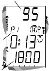
The Pro Plus 2 constantly monitors three critical pieces of information; no decompression status, oxygen accumulation, and breathing gas consumption rate. Refer to the Oceanic Dive Computer Safety and Reference Manual which describes Dive Time Remaining which is a display that indicates the time that is more critical for you at that particular moment (i.e.; whichever time is the least amount available of the three).
Displayed will be either Time Remaining before reaching the No Decompression limit (Fig. 5b), or Time Remaining before reaching the limit for Oxygen Accumulation, or Time Remaining before reaching the End Pressure Alarm set point.
11
|
b |
N2 |
FEET |
|
|
|
MAX |
c |
|
O2 |
PSI |
0 5 10 20
aATR
Fig.6-CylinderPressure
andDepth Displays
ALPHA / NUMERIC DISPLAYS
CylinderPressureDisplay
Cylinder Pressure (Fig 6a) is displayed any time the Pro Plus 2 is connected to a pressurized cylinder and in an active operating mode.
Values of pressure are displayed numerically from 10 PSI (.5 BAR) up to 5000 PSI (352 BAR) in increments of 10 PSI (.5 BAR).
DepthDisplays
During a dive, the Current Depth display (Fig. 6b), indicates depths from 0 to 330 feet (99.9 meters) in 1 foot (.1 meter) increments.
By pressing the Left (Advance) button, the Maximum Depth reached during that dive will be displayed in the center/left portion of the display (Fig. 6c).
During a Decompression Dive, the required Ceiling Stop Depth is displayed in the center of the screen. Maximum Depth can be viewed by pressing the Left (Advance) button.
12

TimeandDate Displays
Time displays are shown in hour:minute format (i.e., 1:16 represents 1 hour and 16 minutes, not 116 minutes!). The colon that separates hours and minutes blinks once per second when the display is indicating real time (e.g., Elapsed Dive Time), and is solid (non-blinking) when times are calculated projections (e.g., Time to Fly).
The Main Time display is located in the lower/middle portion of the display (Fig. 7a) and a second time display (Fig. 7b) is located in the center/right. Both displays are identified by clock icons.
• Time of Day can be set for 12 hour format (Am/Pm) or 24 hour format.
Date is displayed in the center/left portion of the screen only to identify dive data while it is viewed in the Log Mode (see page 70). When Units of Measure are set for 'Imperial', the Month appears to the left of Day. When set for Metric, the Month appears to the right of Day.
TemperatureDisplay
Ambient Temperature is displayed in the center/left portion of the screen (Fig. 7c) while in the Surface Mode and Log Mode, and can be viewed as part of an Alternate Display when the Left (Advance) button is pressed while in a dive mode. If the Temperature exceeds a value of '99', two dashes ( - - ) will be displayed on the screen until the unit's temperature decreases to '99'.
b
N2
FEET
c
a
O2 |
PSI |
0 5 10 20
ATR
Fig.7-TimeandTemperature
Displays
13

NOTE: Eachnumericandgraphicdisplayrepresentsauniquepieceofinformation. It is imperative that you understand the formats, ranges, and values of the informationrepresentedtoavoidanypossiblemisunderstandingthatcouldresult inerror. TheInformationalDisplaysaredescribedindetailasthevariousoperatingmodestheyappearinarepresentedthroughoutthismanual.
AUDIBLEALARM
LEDWarningLight
A red LED Warning Light will light and a Speaker icon will appear when the Audible Alarm emits a tone. They will turn off when the Alarm is acknowledged, and will not activate if the Audible is Set OFF (a user setting).
When warning situations activate the Alarm, the unit will emit a continuous tone for 10 seconds, or until the situation is corrected, or it is acknowledged by the user pressing the Left (Advance) button for 2 seconds. If acknowledged by the user and the situation corrected, the Alarm will sound again upon reentry into the warning situation, or entry into another type of warning situation.
A single short beep (which cannot be disabled) is emitted for the following -
•After the Diagnostic countdown, if everything is okay.
•If the unit automatically returns to Surface Mode from Simulator Mode.
•Upon completion of a Hot Swap battery change with calculations saved.
•Change from Delayed to Full Violation 5 minutes after the dive.
14
Situations that will sound the Alarm, if it is turned ON (a user setting), include -
•Entry into Decompression Mode.
•Air Time Remaining Bar Graph Alarm (a user setting).
•Air Time Remaining = 5 minutes.
•Air Time Remaining = 0 minutes.
•Turn Pressure Alarm (a user setting).
•End Pressure Alarm (a user setting).
•PO2 => than the Max PO2 Alarm (a user setting), or => 1.60 ATA.
•Descent deeper than the Max Depth Alarm (a user setting).
•Tissue Loading Bar Graph Alarm (a user setting).
•Dive Time Remaining Alarm (a use setting).
•Elapsed Dive Time Alarm (a use setting).
•O2 Accumulation => allowable per dive limit, or limit for a 24 hour period.
•Ascending above a required Decompression ceiling stop depth for less than 5 minutes (referred to as a Conditional Violation).
•Ascent rate exceeds 60 feet/minute (18 meters per minute) if greater than 60 feet (18 meters), or 30 feet/minute (9 meters/minute) at 60 feet (18 meters) and shallower.
During the following situations, the 10 second continuoustone willbefollowedby a5 second steady beep that will not turn off when acknowledged, even if it was user Set OFF -
•Ascending above a required Decompression ceiling stop depth for more than 5 minutes (referred to as a Delayed Violation).
•Decompression requires a ceiling stop depth of 70 feet/21 meters or deeper.
•Being on the surface for 5 minutes after a Conditional Violation (Permanent Violation).
15
a
N2
O2
ATR
Fig.8-Battery Indicator
SMARTGLO® BACKLIGHT
To activate the Backlight - press the Right (Select) button.
•The Smart Glo® feature senses the intensity of natural light present. If a low level of light is present, the Backlight will activate and illuminate the display for button depression time plus the user set additional Duration time (3 or 7 seconds).
•Press the button again to activate as desired.
NOTE: Extensive use of the Backlight reduces estimatedBatterylife. Also,theBacklightdoesnot operate during a Low Battery Condition or when downloading data to a PC.
POWER SUPPLY
The Pro Plus 2 utilizes one (1) 3 volt, CR2 Lithium Battery that should provide from 50 dive hours of operation, if you conduct 1 - one hour dive each time the unit is activated, to over 150 dive hours of operation, if you conduct 3 or more one dives each time the unit is activated.
Battery Indicator
A Battery Indicator (Fig. 8a) provides an indication of Battery condition. The Battery Indicator will be displayed during Surface Mode. It will not be displayed during Dive Mode(s).
16

LowBatteryCondition
•Voltage level is checked upon activation and every 10 minutes during operation.
•When 75 % of the Rated Power has been consumed, only the lower bar of the Indicator will be displayed and the full icon will flash (Fig. 9) once per second as a warning that the Battery is to be replaced prior to conducting any further dives.
•Upon decreasing to a voltage level that will no longer sustain proper operation, the Battery Indicator will flash 5 times followed by shutdown of the unit.
•If a Low Battery Condition exists when the unit is manually activated (by pressing the button), the graphic bAT and the Battery Indicator will appear flashing for 5 seconds followed by shutdown of the unit.
•If the button is not pressed to activate the unit prior to a dive (e.g., the unit activated automatically by immersion in water), and a Low Battery Condition exists, the Battery Indicator will appear flashing as a warning upon descent past 4 feet (1.2 meters). No other information will be displayed and the unit will not enter Dive Mode.
N2
O2 |
PSI |
ATR
Fig.9-LowBatteryCondition
17
N2
O2
ATR
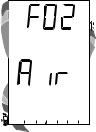
Fig. 10 - FO2 set for AIR
•If the unit did not display a Low Battery Condition prior to entering the Dive Mode, and a Low Battery Condition occurs during the dive, there will be sufficient Battery power to maintain unit operation for the remainder of that dive. The Battery Indicator will appear after the dive upon entry into Surface Mode.
•When the Battery is removed, settings and calculations for repetitive dives will be retained, if a new battery can be inserted within 8 seconds. Otherwise the calculations will reset to zero and settings must be reset.
FO2MODE
After Activation, the Pro Plus 2 will operate as an Air computer without displaying information associated with oxygen calculations, unless it is set for a percentage of oxygen (FO2) other than Air (a numerical value between 21 and 50 %).
When set with an FO2 value of 'Air' (Fig. 10), the Pro Plus 2 will perform calculations the same as if FO2 were set for 21% oxygen, internally accounting for oxygen loading for any subsequent Nitrox dives. However, oxygen related displays, warnings, and the O2 Bar Graph will not appear on the display for that dive, or subsequent dives, unless FO2 is set for a numerical value (21 - 50).
18

Once a dive is made with the unit set as a Nitrox Computer (FO2 set for a numerical value), it cannot be programmed to operate as an Air Computer until 24 hours after the last dive. 'Air' will not be displayed as an option in the FO2 Mode.
However, you can set FO2 for 21% for use with Air.
When FO2 is set at a value of 21% (Fig. 11), the unit will remain set at 21% for subsequent nitrox dives until FO2 is set to a higher value, or until it automatically turns off and is reactivated.
FO250%Default
If the Default function is set to ON (Fig. 12) and FO2 is set to a value 'greater than 21%', the FO2 set point value will automatically revert to 50% 10 minutes after that dive.
The Maximum Depth that can be achieved with a PO2 of 1.60 ATA will also be displayed.
• FO2 must therefore be reset for each repetitive nitrox dive, or the value will automatically 'default' to 50(%) and the dives will be calculated based on 50% O2 (50% nitrogen) for oxygen calculations and 21% O2 (79% nitrogen) for nitrogen calculations.
N2
MAX
O2
ATR
Fig. 11 - FO2 set for 21%
N2
O2
ATR
Fig.12-FO2DefaultON
19
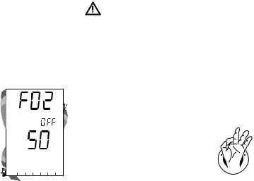
If the Default function is set to OFF (Fig. 13), the FO2 value for repetitive dives remains the same as previously set until the set point is manually changed.
WARNING: When the unit shuts off, the FO2 set point will default to AIR regardless if the 50% Default is set ON or OFF. Always set, or verify, the FO2 set point priortoeachnitroxdive.
Setting FO2 for a nitrox dive is described on page 25.
N2
O2
ATR
Fig.13-FO2DefaultOFF
R
E
S
P
ON
S
I
E BL
D
R |
|
|
E |
I |
V |
20
WARNING: Prior to diving with the Pro Plus 2, you mustalsoreadandunderstandtheOceanicDive ComputerSafetyandReferenceManualwhich providesImportantWarningsandSafetyRecommendationsaswellasgeneralproductinformation.
ACTIVATION and SETUP
21

ACTIVATION
To Activate the Pro Plus 2, press and release the Left (Advance) Button.
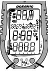
• Upon manual activation, the unit will enter Diagnostic Mode (Fig. 14), displaying all segments of the LCD as 8's, followed by dashes (- -), then a countdown from 9 to 0. Diagnostic Mode checks the display and battery voltage to ensure that everything is within tolerance and functioning properly.
Backup Activation (only if Water Activation is set ON)
As a backup, the Pro Plus 2 will also automatically activate by water contact. This is accomplished by bridging the gap between contacts located on the Button stems and case. The graphic H2O that will be displayed as an indication is described later.
N2 |
DECO |
|
|
|
|
|
M |
|
|
|
|
|
|
|
|
|
FEET |
|
|
|
|
|
|
|
|
MAX |
|
|
|
|
|
|
|
|
TOO |
|
|
|
|
|
|
|
|
FAST |
|
|
|
|
DEMO |
|
|
|
|
|
|
|
MAX |
|
|
|
|
|
|
|
|
|
|
|
|
O2 |
|
O2 O2 |
|
|
|
|
|
|
PSI |
|
|
|
|
|
|
|
|
|
BAR |
|
0 |
5 |
10 |
20 |
30 |
40 |
50 |
60 |
|
ATR |
|
|
|
|
|
|
|
If no dive is made within 2 hours after initial activation, the unit will automatically deactivate. If the wet contacts are still bridged, the unit will reactivate and display the H2O graphic.
WARNING: Iftheunitismanuallyactivatedatelevations higher than 14,000 feet (4,267 meters), it will perform a diagnosticcheckfollowedbyimmediateshutdown.
Fig. 14Diagnostic Mode
22

SURFACEMODE
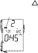
Surface Mode (Fig. 15), identified by the Surface Time icon, follows Diagnostic Mode after Activation. Information includes Dive Number '0' (no dive made yet), Temperature (and icon), Time of Day (with icon), the Battery Consumption Indicator, and Surface Time (with flashing colon).
NOTE: If the wet contacts are bridged, the graphic 'H2O' will appear in place of the dive number '0' (Fig. 16). After the unit is rinsed and dried, '0' will replace 'H2O'.
To activate the Backlight:
• press the Right (Select) button.
AccessingOtherModes
While in the Surface Mode you can access various other Modes that are described in detail throughout this manual.
•Press the Left (Advance) button to access a sequence that includes Plan, Fly, DeSaturation, and Log Modes.
•Press the Right (Select) button to activate the Backlight.
•Press Both buttons (simultaneously) to access Set and Simulator Modes.
N2
O2 |
PSI |
ATR
Fig.15-SurfaceMode
N2
O2 |
PSI |
ATR
Fig.16-SurfaceMode
(rinseanddrytheunit)
23

N2
O2
ATR
Fig. 17 - Set Mode 1
N2
O2
ATR
Fig. 18 - Set Mode 2
SET MODES
Settings are divided into 2 categories. Set Mode #1 includes several settings that you would change more often and Set Mode #2 includes those items not likely to change once you set them. Set Mode 2 can be accessed by first entering settings in Set Mode 1, or by bypassing Set Mode 1.
Settings can be made one after the other, or you can access a specific item that you want to set, bypassing others. Set points can be advanced by scrolling (press/hold) or one increment at a time (press/release < 2 seconds)
Set Mode Access Timing
While in Surface Mode, press Both buttons simultaneously and hold -
•after 2 seconds, SET: 1 appears (Fig. 17)
•after 2 more seconds, SET: 2 appears (Fig. 18)
•Access is gained by releasing the buttons during the 2 second window in which SET: 1 or SET: 2 appears. then pressing the Left (Advance) button.
•If the buttons are held longer, and SET 1 and 2 are both bypassed, the unit will go to Simulator (Demo) Mode which is described on page 75.
•While in the Set Mode, if neither button is pressed during a 2 minute period, the unit will revert to Surface Mode.
24

ENTERING SETTINGS -SET MODE #1
TO SET - FO2 (while in the Surface Mode)
Factory set for AIR, FO2 can also be set to values between 21 and 50% in increments of 1%.
•Press Both buttons simultaneously, release when SET: 1 appears (2 seconds).
•Press and release the Left (Advance) button, FO2 appears with the set point value flashing (Fig. 19).
•Press and release the Right (Select) button repeatedly to increase the FO2 value from 21 to 50% in increments of 1%, then display AIR again; - or - Press and hold the Right (Select) button to scroll from AIR to 32%, then press and hold again to scroll from 32 to 50%, then AIR.
•For each FO2 value that appears, the display indicates the Maximum Depth that can be achieved for a PO2 of 1.60 ATA (Fig. 20a), or the PO2 Alarm set point. If FO2 is set for AIR, no Depth value is displayed.
•Press the Left (Advance) button to accept the setting and advance to Set Depth Alarm, or press and hold Both buttons for 2 seconds to revert to Surface Mode.
N2
O2
ATR
Fig. 19 - Set FO2
N2
MAX
a
O2
ATR
Fig. 20 - FO2 set for 32%
25
N2
FEET
MAX
O2
ATR
Fig. 21 - Set Max Depth Alarm
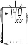
TO SET - MAX DEPTH ALARM
(while in the Surface Mode)
Factory set for 330 feet, the Alarm can be set to values between 30 feet (3 meters) and 330 feet ( 99 meters) in increments of 10 feet (3 meters).
•Press Both buttons simultaneously, release when SET: 1 appears (2 seconds).
•Press and release the Left (Advance) button, FO2 appears with the value flashing.
•Press the Left (Advance) button 1 more time.
•The graphics FEET MAX and dEEP, and Alarm icon appear with the Max Depth set point value flashing (Fig. 21).
•Press and release the Right (Select) button until the desired Depth Alarm value appears; or press and hold to scroll through the set points.
•Press the Left (Advance) button to accept the setting and advance to Elapsed Dive Time Alarm, or press and hold Both buttons for 2 seconds to revert to Surface Mode.
26

TO SET - ELAPSED DIVE TIME ALARM
(while in the Surface Mode)
Factory set for 3:00 (hr:min), the Alarm can be set to values between 0:10 and 3:00 (hr:min) in increments of 5 minutes.
•Press Both buttons simultaneously, release when SET: 1 appears (2 seconds).
•Press and release the Left (Advance) button, FO2 appears with the set point value flashing.
•Press the Left (Advance) button 2 more times.
•The graphic EdT, and Alarm and Dive Time icons appear with the Elapsed Dive Time value flashing (Fig. 22).
•Press and release the Right (Select) button until the desired Alarm value appears; or press and hold to scroll through the set points.
•Press the Left (Advance) button to accept the setting and advance to PC Interface, or press and hold Both buttons for 2 seconds to revert to Surface Mode.
N2
O2
ATR
Fig. 22 - Set Elapsed Dive
TimeAlarm
27
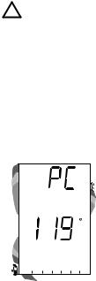
NOTE: For more information regardingPC Interface,referto page 74 of this manualandto documents providedwiththe PCdownload product.
N2
O2
ATR
Fig.23-PCInterface
PC INTERFACE
PC Interface is not a setting, it is included in the Set 1 menu for easy access when data in the unit's memory is to be downloaded (copied) to the PC download software program for storage and viewing.
To download data (while in the Surface Mode)-
•Press Both buttons simultaneously, release when SET: 1 appears (2 seconds).
•Press and release the Left (Advance) button, FO2 appears with the set point value flashing.
•Press the Left (Advance) button 3 more times.
•The graphic PC appears with a 120 second countdown timer (Fig. 23). Download must be initiated before the timer reaches 00 (within 2 minutes).
•Download is initiated by the external device requesting data transfer (i.e., the PC download program).
•The unit reverts to Surface Mode after completion of the Download operation, or after 2 minutes if neither button is pressed.
28

ENTERING SETTINGS -SET MODE #2
These settings are ones that are not likely to change. To save time at the dive site, verify the set points and adjust them as desired prior to departing on the day's dive trip.
TO SET - UNITS OF MEASURE
(while in the Surface Mode)
Factory set for Imperial, Units of Measure can also be set for Metric.
•Press Both buttons simultaneously, release when SET: 2 appears (4 seconds).
•Press and release the Left (Advance) button, the Units screen appears with the graphics FT, F, and PSI (or M, C, and BAR) flashing (Fig. 24).
•Press and release the Right (Select) button to toggle between Imperial and Metric units.
•Press the Left (Advance) button to accept the setting and advance to Set Hour Format, or press and hold Both buttons for 2 seconds to revert to Surface Mode.
To return to Surface Mode at any time while in Set Mode, press and hold Both buttons for 2 seconds.
N2
O2
ATR
Fig.24-SetUnitsofMeasure
29

N2
O2
ATR
Fig. 25 - Set Hour Format
TO SET - HOUR FORMAT (while in the Surface Mode) Factory set for 12 Hr (12: Am to 11: Pm), the Format can also be set for 24 Hr (0: to 23: hours).
•Press Both buttons simultaneously, release when SET: 2 appears (4 seconds).
•Press and release the Left (Advance) button, the Units screen appears with the set point flashing.
•Press the Left (Advance) button 1 more time.
•The graphic Hour appears with 12 (or 24) flashing (Fig. 25).
•Press and release the Right (Select) button to toggle between 12 and 24.
•Press the Left (Advance) button to accept the setting and advance to Set Hour, or press and hold Both buttons for 2 seconds to revert to Surface Mode.
30
 Loading...