


VTX OPERATING MANUAL
VTX
DIVE COMPUTER
OPERATING MANUAL
© 2002 Design, 2014 |
1 |
Doc. No. 12-5382-r01 (10/24/14) |

VTX OPERATING MANUAL
Welcome
to
Oceanic
and
Thank You
for choosing the
VTX
© 2002 Design, 2014 |
2 |
Doc. No. 12-5382-r01 (10/24/14) |

VTX OPERATING MANUAL
Contents
NOTICES............................................................................................... |
4 |
ACTIVATION AND OVERVIEW............................................................. |
5 |
ACTIVATION...................................................................................... |
6 |
MENU SYSTEM................................................................................. |
6 |
SAMPLE DISPLAYS, ICONS, Abbreviations............................. |
7 |
POWER SUPPLY............................................................................... |
8 |
Power Saver Mode....................................................................... |
8 |
VTX BATTERY STATUS.................................................................... |
8 |
Low Battery Warning, Alarm....................................................... |
8 |
TRANSMITTER (TMT) BATTERY STATUS...................................... |
8 |
BRIGHTNESS CONTROL................................................................. |
9 |
Adjust Brightness........................................................................ |
9 |
AUDIBLE ALARM............................................................................. |
9 |
OPERATING MODES...................................................................... |
10 |
HOME MODE....................................................................................... |
11 |
HOME MENU................................................................................... |
12 |
My Info......................................................................................... |
12 |
DC Info........................................................................................ |
12 |
Clear NI-O2 Calculations........................................................... |
12 |
Home Setup Menu...................................................................... |
13 |
Set Auto Dim........................................................................... |
13 |
Set Date, Time Menu.............................................................. |
13 |
Battery/TMT Status................................................................ |
13 |
Bluetooth................................................................................ |
14 |
NORM/GAUG Log Mode............................................................ |
15 |
NORM/GAUG History Mode....................................................... |
15 |
NORM SURFACE MODE.................................................................... |
16 |
NORM SURF MAIN......................................................................... |
17 |
AdJUST BRIGHTNESS.................................................................. |
17 |
NORM SURF alts.......................................................................... |
17 |
NORM MENU................................................................................... |
18 |
Plan Mode................................................................................... |
18 |
Set Gas Menu............................................................................. |
18 |
Set TMT Menu (NORM, GAUG).................................................. |
19 |
Set Alarms Menu........................................................................ |
20 |
Set Utilities Menu....................................................................... |
20 |
Set Preview................................................................................. |
20 |
View Preview............................................................................... |
21 |
DIVE MODE FEATURES..................................................................... |
21 |
TRANSMITTER SIGNAL RECEPTION GUIDE............................... |
23 |
PROXIMITY OF THE TMTS and VTX............................................ |
23 |
Link Interruption Underwater.................................................... |
23 |
OVERVIEW OF AUTO DIM............................................................. |
23 |
WET ACTIVATION........................................................................... |
24 |
BAR GRAPHS................................................................................. |
24 |
ALGORITHM.................................................................................... |
24 |
CONSERVATIVE FACTOR.............................................................. |
24 |
DEEP STOP..................................................................................... |
24 |
SAFETY STOP................................................................................. |
25 |
DIVE TIME REMAINING (DTR)....................................................... |
25 |
No Deco DTR (NDC)................................................................... |
25 |
O2 DTR (OTR)............................................................................. |
25 |
Gas Time Remaining (GTR)....................................................... |
25 |
NORM DIVE MODES........................................................................... |
26 |
NO DECO MAIN.............................................................................. |
27 |
AdJUST BRIGHTNESS.................................................................. |
27 |
NO DECO alt................................................................................. |
27 |
DEEP STOP (DS)............................................................................. |
27 |
SAFETY STOP (SS)........................................................................ |
28 |
DECOMPRESSION......................................................................... |
28 |
VIOLATION MODES........................................................................ |
29 |
HIGH PO2........................................................................................ |
30 |
HIGH O2........................................................................................... |
31 |
GAS/TMT SWITCHING........................................................................ |
32 |
OVERVIEW...................................................................................... |
33 |
NORM GAS SWITCH MENU........................................................... |
33 |
GAUG TMT SWITCH MENU........................................................... |
33 |
GAUG OP MODE................................................................................. |
34 |
GAUG SURF MAIN.......................................................................... |
35 |
AdJUST BRIGHTNESS.................................................................. |
35 |
GAUG SURF alts.......................................................................... |
35 |
GAUG MENU................................................................................... |
35 |
Set Alarms Menu........................................................................ |
36 |
Set Utilities Menu....................................................................... |
36 |
View Preview............................................................................... |
36 |
GAUG DIVE MAIN........................................................................... |
37 |
Adjust Brightness...................................................................... |
37 |
GAUG Dive ALT.......................................................................... |
37 |
Delayed Violation....................................................................... |
37 |
FREE DIVE OP MODE........................................................................ |
38 |
FREE SURF MAIN........................................................................... |
39 |
AdJUST BRIGHTNESS.................................................................. |
39 |
FREE SURF alts........................................................................... |
39 |
FREE MENU.................................................................................... |
40 |
Countdown Timer....................................................................... |
40 |
Set Menu..................................................................................... |
40 |
FREE DIVE MAIN............................................................................ |
41 |
Adjust Brightness...................................................................... |
41 |
FREE Dive ALT........................................................................... |
41 |
FREE DIVE ALARMS...................................................................... |
41 |
COMPASS MODE................................................................................ |
43 |
COMPONENTS................................................................................ |
44 |
OVERVIEW...................................................................................... |
45 |
COMPASS MENU............................................................................ |
45 |
NORTH OP MAIN............................................................................ |
45 |
REFERENCE OP MAIN................................................................... |
45 |
REFERENCE MENU........................................................................ |
46 |
CALIBRATION................................................................................. |
46 |
DECLINATION................................................................................. |
47 |
ALARMS.......................................................................................... |
47 |
NORM/GAUG DIVE MODE ALARMS................................................. |
48 |
REFERENCE....................................................................................... |
51 |
UPLOADING/DOWNLOADING....................................................... |
52 |
USB Connection......................................................................... |
52 |
PC/Mac Requirements............................................................... |
52 |
ALTITUDE SENSING AND ADJUSTMENT.................................... |
53 |
CARE AND CLEANING................................................................... |
53 |
INSPECTIONS AND SERVICE........................................................ |
53 |
BATTERY REPLACEMENT............................................................ |
54 |
Data Retention............................................................................ |
54 |
TRANSMITTER BATTERY REPLACEMENT.................................. |
55 |
TRANSMITTER INSTALLATION ON A REGULATOR................... |
55 |
TECHNICAL DATA.............................................................................. |
56 |
SPECIFICATIONS........................................................................... |
57 |
DSAT ALGORITHM NDL CHART................................................... |
60 |
ALTITUDE LEVEL CHART.............................................................. |
60 |
Z+ ALGORITHM NDL CHART........................................................ |
61 |
ADDITIONAL INFORMATION - BRIGHTNESS & POWER............ |
62 |
INSPECTION/SERVICE RECORD...................................................... |
63 |
oceanic WORLDWIDE..................................................................... |
63 |
© 2002 Design, 2014 |
3 |
Doc. No. 12-5382-r01 (10/24/14) |

VTX OPERATING MANUAL
NOTICES
LIMITED TWO-YEAR WARRANTY
For details, refer to the Product Warranty Registration Card provided. Register on line at www.oceanicworldwide.com
COPYRIGHT NOTICE
This operating manual is copyrighted, all rights are reserved. It may not, in whole or in part, be copied, photocopied, reproduced, translated, or reduced to any electronic medium or machine readable form without prior consent in writing from Oceanic/2002 Design.
VTX Operating Manual, Doc. No. 12-5382
© 2002 Design, 2014
San Leandro, CA USA 94577
TRADEMARK, TRADE NAME, AND SERVICE MARK NOTICE
Oceanic, the Oceanic logo type, VTX, the VTX logo, GasTime Remaining (GTR), Diver Replaceable Batteries, Graphic Diver Interface, Tissue Loading Bar Graph (TLBG), Pre Dive Planning Sequence (PDPS), Set Point, Control Console, Turn Gas Alarm, and Dual Algorithm are all registered and unregistered trademarks, trade names, and service marks of Oceanic. All rights are reserved.
PATENT NOTICE
U.S. Patents have been issued, or applied for, to protect the following design features:
Dive Computer with Free Dive Mode and Wireless Data Transmission (U.S. Patent no. 7,797,124), Dive Computer with Free Dive Mode (U.S. Patent no. 8,600,701), and Air Time Remaining (U.S. Patent no. 6,543,444). Other patents pending. User Setable Display (U.S. Patent no. 5,845,235) is owned by Suunto Oy Finland.
DECOMPRESSION MODEL
The programs within the VTX simulate the absorption of nitrogen into the body by using a mathematical model. This model is merely a way to apply a limited set of data to a large range of experiences. The VTX dive computer model is based upon the latest research and experiments in decompression theory.
Still, using the VTX, just as using the U.S. Navy (or other) No Decompression Tables, is no guarantee of avoiding decompression sickness, i.e. “the bends.” Every diver’s physiology is different, and can even vary from day to day. No machine can predict how your body will react to a particular dive profile.
fcc ID: MH8A
FCC Compliance:
This equipment complies with Part 15 of the FCC Rules. Operation is subject to the following two conditions: 1.) this equipment may not cause harmful interference, and 2.) this equipment must accept any interference received, including interference that may cause undesired operation.
FCC Interference Statement:
This equipment has been tested and found to comply with the limits for an Intentional Radiator, a Class B Digital Device, pursuant to Part 15 of FCC Rules, Title 47 of the Code of Federal Regulations. These rules are designed to provide reasonable protection against harmful interference in a commercial or residential installation. This equipment generates, uses and can radiate radio frequency energy and, if not installed and used in accordance with the instructions, may cause harmful interference to radio communications.
There is no guarantee that interference will not occur in a particular installation. If this equipment does cause interference to radio or television reception, which can be determined by turning the equipment off and on, the user is encouraged to try to correct the interference by one or more of the following measures:
•Reorient or relocate the receiving antenna.
•Increase the separation between the equipment and receiver.
•Connect the equipment to an outlet on a circuit different from that to which the receiver is connected.
•Consult the dealer or an experienced radio/TV technician.
Warning: Changes or modifications to this unit not expressly approved by Oceanic/2002 Design could void the user's authority to operate the equipment.
Pay special attention to items marked with this Warning symbol.
© 2002 Design, 2014 |
4 |
Doc. No. 12-5382-r01 (10/24/14) |

VTX OPERATING MANUAL
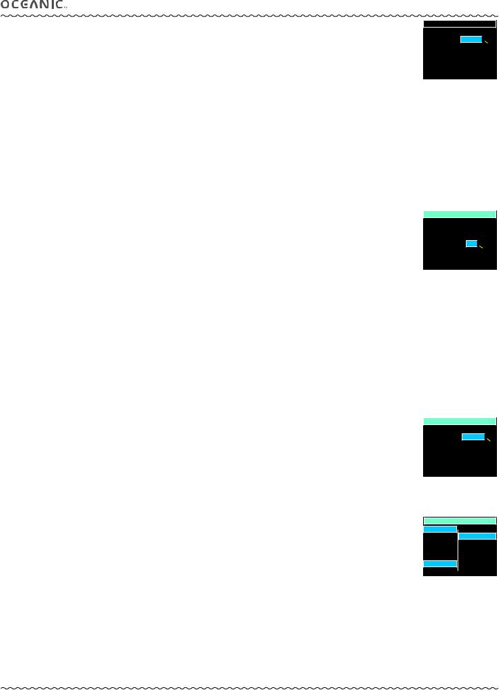
ACTIVATION
and
OVERVIEW
© 2002 Design, 2014 |
5 |
Doc. No. 12-5382-r01 (10/24/14) |
VTX OPERATING MANUAL
INTERACTIVE CONTROL CONSOLE
The interactive control console utilizes 3 control buttons that are referred to as M, A, and S (Fig. 1).
• M (left front) - Menu, Mode, Minus (decrease)
• A (right front) - Advance, Add (increase).
• S (right side) - Select, Save.
|
M |
S |
Activation |
A |
|
To activate the VTX, press/release any button. |
Fig. 1 - Control Buttons |
|
•An Oceanic welcome screen will be displayed for 3 seconds (Fig. 2)* during which diagnostics will be performed verifying that sensors and battery voltage are within tolerance.
*After the Battery is replaced on a new day prior to performing any dives, a message is displayed before the welcome.
•It will also check ambient barometric pressure, and calibrate present depth as 0. When at 3001 feet (916 meters), or higher, it will adjust depth for the higher altitude.
•After the diagnostic check, the Home Menu screen will be displayed (Fig. 3) allowing you to select what you would like to do (view information, perform setup, access operating modes).
•If no button is pressed within 2 minutes, the unit will enter PSM (Power Saver Mode) turning the screen off. Refer to page 8.
•If no dive is made within 2 hours, the unit will shut Off.
Wet activation contacts will automatically activate the unit and cause it to enter dive mode when the contacts become wet and it senses depth of 5 FT (1.5 M). They will not inadvertently activate Surface Mode such as when in a wet gear bag.
MENU SYSTEM
The viewing area is used to display alpha numeric messages and measured values as well as menu type systems for selection of settings and various auxiliary functions. It also serves as the Digital Compass.
Menus which are identified by function such as Main, Set, and Switch. The items available within the menus vary according to the mode you are in at the time. Some settings, such as for Units, are common throughout the modes and can be changed in any Utilities Menu.
•Home Menu
>>Home Setup Menu
>>Set Date Time Menu
•NORM Surface Main Menu
>>Set Gas Menu
>>Set TMTs Menu
>>Set Alarms Menu
>>Set Utilities Menu
>>Set Preview Menu
•NORM Dive Menu
>>Gas/TMT Switch Menu
•GAUG Surface Main Menu
>>Set TMTs Menu
>>Set Alarms Menu
>>Set Utilities Menu
•GAUG Dive Menu
>>TMT Switch Menu
•FREE Surface Main Menu
>>Set Menu
•Compass Surface Menu
>>Reference Menu
>>Set Declination Menu
•Compass Dive Menu
>>Reference Menu
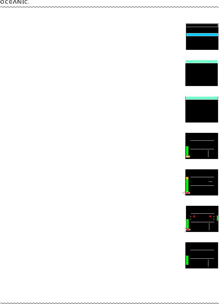
Upon entering a menu, movement through it starts at the first (top) selection, then continues in a rolling manner down the screen. Items or selections are generally shown in columns of up to 7 items. Additional items form a second column (Fig. 4).
Typical button operations within menu systems >>
A (< 2 sec) - to step down the screen (forward) through selections.
M (< 2 sec) - to step up the screen (backward) through selections.
S (< 2 sec) - to select or access the item highlighted.
S (2 sec) - to step back to the menu after the item is selected.
M (2 sec) anytime, or no button action for 2 minutes - will revert to Home or the Surface Main.
Fig. 2 - Diagnostic Check (for 3 sec, then Home Menu)
WAIT FOR BEEP
THEN ACTIVATE
Fig. 2A - Message given after Battery Change on new day
HOME MENU
MY INFO |
NORM |
DC INFO |
GAUG |
SETUP |
FREE |
LOG |
COMPASS |
HISTORY |
|
Fig. 3 - Home Menu
(after Diagnostics)
NORM SET PREVIEW
GAS 1 |
TLBG AL |
GAS 2 |
WATER |
GAS 3 |
DEEP STOP |
GAS 4 |
SAFE STOP |
DEPTH AL |
TURN AL |
EDT AL |
END AL |
DTR AL |
|
Fig. 4 - Sample Menu (13 items, 2 columns)
© 2002 Design, 2014 |
6 |
Doc. No. 12-5382-r01 (10/24/14) |
VTX OPERATING MANUAL
|
|
|
|
SAMPLE DISPLAY LAYOUTS |
|
|
|
|
||||
SURFACE MAIN |
|
|
|
|
SET MENU |
|
|
|
DIVE MAIN |
|
||
|
|
|
|
|
|
|
|
|
||||
SURF |
0: 04 |
NORM SET ALARMS |
|
|
|
86 FT |
||||||
AUDIBLE = ON |
|
|
|
|
||||||||
NDC |
EDT |
DEPTH = 130 FT |
|
|
NDC |
EDT |
||||||
- : - - |
0:32 |
|
TLBG = 8 SEG |
|
|
0:24 0:35 AR |
||||||
|
|
|
|
|
EDT = 0:40 |
|
|
|
|
|
|
|
GAS 1 |
GTR |
|
DTR = 0:10 |
|
|
|
DS GAS 1 |
GTR |
||||
1799PSI |
- - |
|
END = 300 PSI |
|
TL |
1480 PSI |
42 |
|||||
|
|
|
|
|
TURN = 1500 PSI |
|
|
|
|
|||
|
|
|
DISPLAY ICONS & GRAPHIC ABBREVIATIONS |
|
|
|
||||||
|
|
|
(Full character graphics, such as AUDIBLE, are not listed below.) |
|
|
|||||||
|
A, AM |
|
= Am (time) |
|
|
M |
= Meters (depth) |
|
|
|
|
|
|
AL |
|
= Alarm |
|
|
M.D |
= Month & Day (date) |
|
|
|
|
|
|
AR |
|
= Ascent Rate Indicator |
|
MAX |
= Maximum |
|
|
|
|
||
|
AV |
|
= Average |
|
|
MIN |
= Minimum, Minutes (time) |
|
|
|||
|
AVAIL |
|
= Available |
|
|
N |
= North (compass) |
|
|
|
|
|
|
BAR |
|
= Metric unit (pressure) |
|
NDC |
= No Deco Time Remaining |
|
|
||||
|
BT |
|
= Bluetooth |
|
|
NDL |
= No Deco Limit (time) |
|
|
|
||
|
C |
|
= Centigrade (temperature) |
|
NI |
= Nitrogen |
|
|
|
|
||
|
CAL |
|
= Calibration (compass) |
|
No. |
= Number |
|
|
|
|
||
|
CDT |
|
= Countdown Timer |
|
|
NORM, NOR = Normal Scuba Mode |
|
|
||||
|
CONSERV = Conservative Factor |
|
O2 |
= Oxygen |
|
|
|
|
||||
|
D.M |
|
= Day & Month (date) |
|
|
OTR |
= O2 Time Remaining |
|
|
|
||
|
DA |
|
= Depth Alarm |
|
|
P, PM |
= Pm (time) |
|
|
|
|
|
|
DC |
|
= Dive Computer |
|
|
PO2 |
= Partial Pressure of O2 (ATA) |
|
|
|||
|
DECO |
|
= Decompression |
|
|
PSI |
= Pounds per Square Inch (pressure) |
|
|
|||
|
DESAT |
|
= Desaturation (nitrogen) |
|
RTI |
= Repeating Time Interval |
|
|
|
|||
|
DS |
|
= Deep Stop |
|
|
S |
= South (compass) |
|
|
|
|
|
|
DSAT |
|
= Algorithm type |
|
|
SAT |
= Saturation |
|
|
|
|
|
|
DTR |
|
= Dive Time Remaining |
|
SEC |
= Seconds (time) |
|
|
|
|
||
|
E |
|
= East (compass) |
|
|
SEG |
= Segments (bar graph) |
|
|
|
||
|
EDT |
|
= Elapsed Dive Time |
|
|
SI |
= Surface Interval |
|
|
|
|
|
|
EL, ELEV |
= Elevation (altitude level) |
|
SPG |
= Submersible Pressure Gauge |
|
|
|||||
|
EMERG. |
= Emergency |
|
|
SURF |
= Surface (mode, time) |
|
|
|
|||
|
F |
|
= Fahrenheit (temperature) |
|
TAT |
= Total Ascent Time (deco) |
|
|
||||
|
FO2 |
|
= Fractional % of Oxygen |
|
TEMP |
= Temperature |
|
|
|
|
||
|
FREE |
|
= Free Dive Mode |
|
|
TL, TLBG = Tissue Loading Bar Graph |
|
|
||||
|
FT |
|
= Feet (depth) |
|
|
TMT |
= Transmitter (tank pressure) |
|
|
|||
|
GAUG, GAU = Digital Gauge Scuba Mode |
W |
= West (compass) |
|
|
|
|
|||||
|
GTR |
|
= Gas Time Remaining |
|
Z+ |
= Algorithm type |
|
|
|
|
||
|
INFO |
|
= Information |
|
|
|
|
|
|
|
|
|
© 2002 Design, 2014 |
7 |
Doc. No. 12-5382-r01 (10/24/14) |
VTX OPERATING MANUAL
POWER SUPPLY
•VTX Battery >> (1) 3 vdc, CR2, Lithium, 800 mAh - Duracell, Energizer, Panasonic, or RayOvac recommended.
•Use life (examples) >> 15 hours at 100% Brightness with Auto Dim set OFF; 34 hours at 60% Brightness with Auto Dim To time set for 10 seconds and Dim level set for 10%. Refer to page 62 for more information relating to power usage.
|
|
SETUP MENU |
|
Once a low battery alarm condition occurs (red icon flashing), sufficient time should be available to |
SET AUTO DIM |
|
|
ascend to the surface while Brightness is held to 60% maximum. |
SET DATE, TIME |
|
|
BATT, TMT STATUS |
|
||
|
|
BLUETOOTH |
|
•Transmitter Battery (each) >> (1) 3 vdc, CR2, 800 mAh, Lithium.
•Use life >> 300 dive hours if (2) 1 hour dives per dive day.
• Replacement >> by user (annual recommended). |
|
|
Fig. 5 - HOME SETUP MENU |
||
|
||
|
(to access Battery Status) |
POWER SAVER MODE (PSM)
When 2 minutes elapse without any button being pressed while on the surface, the unit will enter a Power Saver Mode (PSM) which turns the display screen off until a button is pressed at which time it will turn back on.
During the time that the screen is off, operations continue as normal in the background with current updated information displayed after the screen comes on again.
An Auto Dim feature can also be used to save power during dives by dimming the display screen to a % level of Brightness that you set prior to the dives. Oceanic recommends that you take advantage of this feature. Refer to pages 13 and 62.
BATTERY STATUS
To access, while viewing the Home Menu when on the surface >>
•S (< 2 sec) to access Home Setup Menu, then -
•A or M (< 2 sec) until BATT, TMT STATUS is highlighted (Fig. 5).
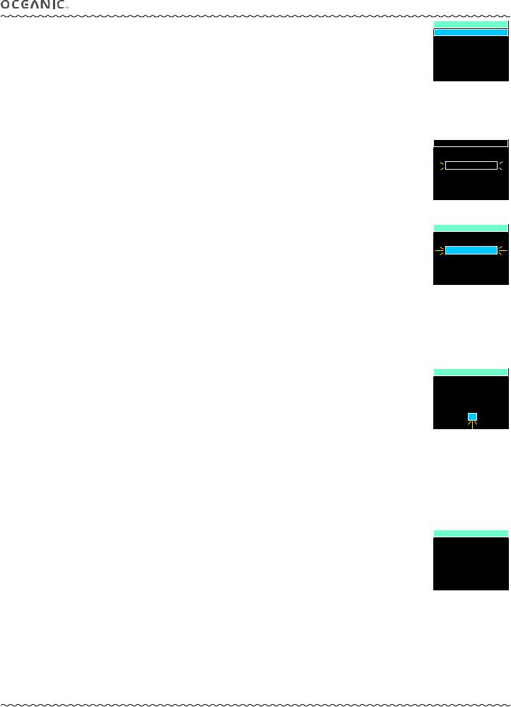
•S (< 2 sec) then activates the unit's receiver displaying a Please Wait message (Fig. 6A) for 3 seconds, then the Status screen appears (Fig. 6B).
A color coded Low Battery icon is displayed at the lower/left of Surface and Dive Main screens when battery power is low.
•No icon = means battery power is good and you have sufficient power to conduct normal diving activities.
•Yellow = caution (warning), meaning you should have sufficient battery power to complete a normal 1 hour dive.
•Red (while on the surface) = alarm, meaning the battery must be changed prior to starting a dive.
•Red (during a dive) = alarm, meaning you should savely ascend to the surface and replace the battery before continuing with diving activities. Caution - The unit may shut off at any time without further warning.
LOW BATTERY WARNING
•The Battery icon will be displayed (yellow) when voltage decreases to 2.75 vdc.
•Battery change prior to any diving is recommended. Less than 1 hour dive time may be expected.
•The graphics LOW BATTERY will alternate with NORM (or GAUG or FREE) on the Surface Main (Fig. 7).
•If a dive is started, the graphic is not displayed on the dive mode screens.
•Brightness level will be limited to 60% with other functions continuing as usual.
BATT, TMT STATUS
PLEASE WAIT . . .
SEARCHING FOR -
BATT/TMT
Fig. 6A - BATTERY STATUS
MESSAGE
BATT, TMT STATUS
VTX = BATT GOOD
TMT 1 = BATT GOOD
TMT 2 = BATT LOW
TMT 3 = NOT AVAIL
TMT 4 = OFF
Fig. 6B - BATTERY STATUS
SURF 1:03
LOW
BATTERY
GAS 1 |
DIVE |
TL 850PSI |
1 |
Fig. 7 - VTX
LOW BATTERY WARNING
SURF 0:11
 CHANGE
 BATTERY
GAS 1 |
DIVE |
TL 380PSI |
5 |
Fig. 8A - LOW BATTERY
ALARM (on surface)
LOW BATTERY ALARM |
|
|
|
64 FT |
|||
• The Battery icon will change from yellow to red (flashing) when voltage decreases to 2.50 vdc. |
|
|
|
||||
|
|
|
|
|
|
|
|
• Entry into dive modes and compass use is blocked. Battery change is required prior to starting any dives. |
|
|
|
GO UP |
|
|
|
• The graphics CHANGE BATTERY (red) will flash on the Surface Main (Fig. 8A) until the battery is changed or the unit shuts |
|
|
|
|
|
|
|
|
|
|
LOW BATTERY |
||||
off due to voltage being too low to sustane operations. |
|
|
|
||||
|
|
|
|
|
AR |
||
|
|
|
|
GAS 1 |
GTR |
||
• If a dive is in progress, the red Battery icon will flash and the graphics GO UP LOW BATTERY (red) will be displayed with 2 |
|
TL 1320 PSI |
36 |
|
|||
|
|
||||||
red Up Arrows (Fig. 8B) that will alternate with the usual information displayed until on the surface. |
|
|
Fig. 8B - LOW BATTERY |
||||
Ascent should be made to the surface following proper ascent protocols, respecting ascent speeds |
|
|
ALARM (during dive) |
||||
|
|
|
|
|
|
|
|
allowed, and Deco and Safety Stops if possible. |
1:03 |
SURF |
TRANSMITTER (TMT) BATTERY STATUS
Indication is provided only while on the surface.
Low Battery Warning
•The graphics BATT LOW appear solid (yellow) on the Status screen (see Fig. 6B).
•DC functions continue to be available (surface and dive).
Low Battery Alarm
•The graphics TMTx LOW BATTERY (red) alternate with the graphics NORM (or GAUG) on the SURF Main screen (Fig. 9).
•The graphics BATT LOW (red) also flash on the Status screen.
•TMT operation continues until Tank Pressure decreases to 50 PSI at which time the TMT's link is lost.
TMT 1
LOW BATTERY
GAS 1 |
DIVE |
TL 850PSI |
1 |
Fig. 9 - TMT LOW BATTERY
ALARM
© 2002 Design, 2014 |
8 |
Doc. No. 12-5382-r01 (10/24/14) |

VTX OPERATING MANUAL
BRIGHTNESS CONTROL
The level (%) of screen Brightness can be adjusted by accessing the Brightness Adjustment screen while viewing the Home Menu screen, or a Surface or Dive Main screen (NORM, GAUG, or FREE), or the Compass OP Main screen.
•A (2 sec), while on the surface or during dives, will access a Brightness adjustment screen with the last % highlighted and flashing. During a Low Battery Warning or Alarm condition, the level will be limited to 60% maximum.
ADJUST BRIGHTNESS, information is to include (Fig. 10): |
ADJUST BRIGHTNESS |
> xx % (last value saved), flashing. |
|
•S (2 sec) to step back to the screen from which access was gained without changing the % value.
•A (< 2 sec) to step upward through values of 10% to 100% one at a time in increments of 10%.
•M (< 2 sec) to step down through values one at a time.
•S (< 2 sec) to save the % setting and revert to the screen from which access was gained.
TIP: When an adjustment is made during a dive that is lower than the Auto Dim % set prior to the dive, the screen will remain illuminated at the level you save until you adjust it to a % level above the Auto Dim % set.
audible alarm
While operating in NORM or GAUG Mode, the Audible will emit 1 beep per second for 10 seconds when alarms strike, unless it is set Off. During that time, the Audible can be acknowledged and silenced by pressing S (< 2 sec).
The Audible will not be active when it is set OFF (a Set Alarms Menu selection).
FREE Dive Mode alarms, which emit 3 short beeps either 1 or 3 times, cannot be acknowledged or set OFF.
Alarms that strike during operations in Compass Mode are described on page 45.
Situations that will activate the NORM/GAUG 10 second Alarm include -
** Items apply only in NORM mode.
•Gas Time Remaining (GTR) at 5 minutes, then again at 0 minutes.
•Turn Pressure at the value set (Transmitter 1 only).
•End Pressure at the value set (active Transmitter).
•Descent deeper than the Depth Alarm value set.
•Dive Time Remaining at the value set**.
•Elapsed Dive Time at the value set.
•PO2 level at .20 < value set for the gas in use and again at the value set**.
•O2 accumulation at 240 OTU (80%), then again at 300 OTU (100%)**.
•TLBG at the value set**.
•Ascent Rate (alarm = all 5 segments) exceeds 60 FPM (18 MPM) when deeper than 60 FT (18 M), or 30 FPM (9 MPM) at 60 FT (18 M) and shallower.
•Loss of the active Transmitter Link signal for more than 15 seconds during a dive.
•Entry into Decompression (Deco)**.
•Conditional Violation (above a required Deco Stop Depth < 5 minutes)**.
•Delayed Violation (above a required Deco Stop Depth => 5 minutes)**.
•Delayed Violation (a Deco Stop Depth > 60 FT/18 M is required)**.
•Delayed Violation (Depth > 330 FT/100 M).
•A Gas Switch would expose the diver to PO2 => 1.60 ATA for that gas**.
A single short beep (which cannot be disabled) sounds when -
• 5 minutes elapse on the surface after the Violation dive.
3 short beeps (which cannot be disabled) sound when -
•Ascent Rate (warning = 4 segments) is 51 to 60 FPM (15.1 to 18 MPM) when deeper than 60 FT (18 M), or 26 to 30 FPM (7.5 to 9 MPM) at 60 FT (18 M) and shallower.
•FREE Dive Repeating Time Interval Alarm - 3 beeps once every 30 seconds, if set On.
•FREE Dive Depth Alarms 1, 2, 3 - 3 beeps 3 times at each value set.
•FREE Dive TLBG Alarm (Caution zone, 7 segments) - 3 beeps 3 times.
•FREE Dive Violation - 3 beeps 3 times upon entry into Decompression.
•FREE Countdown Timer - 3 beeps 3 times when time counts down to 0:00.
During the following situations, the audible will not turn off when acknowledged -
•Delayed Violations 1, 2, 3.
•Deco Stop Depth Violation => 70 FT/21 M stop required.
•FREE mode alarms.

 20%
20% 

Fig. 10 - BRIGHTNESS
ADJUSTMENT
© 2002 Design, 2014 |
9 |
Doc. No. 12-5382-r01 (10/24/14) |
VTX OPERATING MANUAL
OPERATING MODES
HOME >> This is a base mode that provides access to general items common to the operating dive modes.
NORM >> This is an operating dive mode used for Air and Nitrox scuba activity with up to 4 gases and transmitters.
If no previous dive has been taken within the past 24 hours, NORM is the default mode upon activation with others accessed as described later.
GAUG >> This is an operating dive mode used for scuba activity with up to 4 transmitters but without Ni-O2 calculations.
Once a GAUG dive has been conducted, operation locks into this mode for 24 hours.
FREE >> This is an operating dive mode used for breath hold diving activity with depth/time indication.
Ni-O2 calculations are performed while in FREE mode and are carried over between NORM and FREE.
COMPASS >> This is the navigation mode that can be used at any time while on the surface and during dives.
At any time while operating in Surface Modes*, operation will enter the Dive Mode selected upon descent to 5 FT (1.5 M) for 5 seconds.
*When a Low Battery Alarm condition is present, BATT icon is red, entry into Dive Modes is blocked.
Operation shifts from Dive Mode to Surface Mode upon ascent to 2 FT (0.6 M) for 1 second; however, most surface mode screens will not be available until a transition time elapses.
The reason for this is that making a descent during the first 10 minutes after surfacing from a NORM or GAUG dive, or during the first 1 minute after surfacing from a FREE dive, is a continuation of that same dive.
A descent made after the 10 minute (or 1 minute) interval has elapsed is then considered a new dive.
During the first 10 minutes after surfacing from a NORM or GAUG dive, or the first 1 minute after surfacing from a FREE dive, the Dive Main screen will be displayed with Surface Interval time replacing Current Depth. Dive ALTs can be accessed to view other information pertaining to that dive.
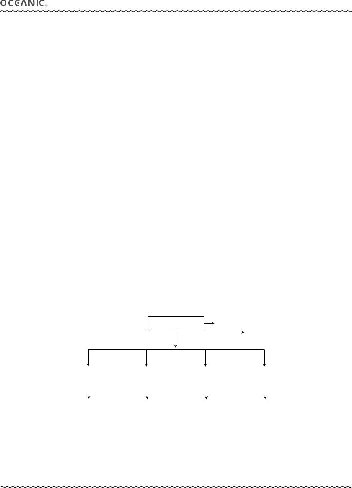
MODE STRUCTURE
HOME MENU
MY INFO |
|
|
DC INFO |
SETUP MENU |
|
SETUP |
|
SET AUTO DIM |
|
||
LOG |
SET DATE, TIME |
|
HISTORY |
BATT, TMT STATUS |
|
|
|
BLUETOOTH |
NORM MODE |
|
GAUG MODE |
|
FREE MODE |
|
|
|
|||
|
|
|
COMPASS MODE |
|||||||
|
|
|
|
|
|
|
|
|
|
|
|
|
|
|
|
|
|
|
|
|
|
NORM MENU |
|
GAUG MENU |
|
FREE MENU |
|
COMPASS MENU |
||||
PLAN |
|
SET TMTS |
|
CDT SETUP |
|
NORTH MODE |
||||
SET GAS |
|
SET ALARMS |
|
SET MENU |
|
REF MODE |
||||
SET TMTS |
|
SET UTILITIES |
|
|
|
|
CALIBRATE |
|||
SET ALARMS |
|
VIEW PREVIEW |
|
|
|
|
SET DECLINATION |
|||
SET UTILITIES |
|
|
|
|
|
|
|
|
|
|
SET PREVIEW |
|
|
|
|
|
|
|
|
|
|
VIEW PREVIEW |
|
|
|
|
|
|
|
|
|
|
© 2002 Design, 2014 |
10 |
Doc. No. 12-5382-r01 (10/24/14) |
VTX OPERATING MANUAL
HOME
MODE
© 2002 Design, 2014 |
11 |
Doc. No. 12-5382-r01 (10/24/14) |

HOME MENU
The Home Menu is displayed after activation and diagnostics. When the NORM, GAUG, FREE, or Compass Surface Main screen is displayed, the Home Menu can be accessed by pressing M for 2 seconds.
•At any time while operating in the Home Menu system, pressing M (2 sec) will revert to the Home Menu screen.
•Operation will also revert to the Home Menu screen if no button is pressed within a 2 minute period.
Selections include (Fig. 11) -
>MY INFO - select to view personal information entered using the PC or Mac interface program.
>DC INFO - select to view information describing the dive computer, or to clear residual Ni-O2 used for calculations.
>SETUP - select to access the Setup Menu.
>LOG - select to access the NORM/GAUG Log data recorded for viewing.
>HISTORY - select to access the NORM/GAUG History data recorded for viewing.
>NORM - select to access the NORM operating mode for scuba activities.
>GAUG - select to access the GAUG operating mode for scuba activities.
>FREE - select to access the FREE operating mode for breath hold diving activities.
>COMPASS - select to access the Compass operating mode for navigation.
VTX OPERATING MANUAL
HOME MENU
MY INFO |
NORM |
DC INFO |
GAUG |
SETUP |
FREE |
LOG |
COMPASS |
HISTORY |
|
Fig. 11 - HOME MENU
•A (2 sec) - to access Adjust Brightness (refer to page 8).
•A (< 2 sec) - to step forward (down) through the Menu selections. Down the left column, then down the right column.
•M (< 2 sec) - to step back (up) through the selections.
•S (< 2 sec) - to access the highlighted selection.
MY INFO (view only)
Up to 7 lines of information containing up to 16 characters each can be entered using the PC or Mac interface system.
Prior to personal information being entered, a graphic message is displayed as a reminder to enter your data (Fig. 12A).
Examples of information that can be entered include (Fig. 12B):
>Name.
>Phone number.
>Address.
>Medical.
>Emergency contact.
• S (2 sec) - to step back to the Home Menu.
DC INFO (view only)
This information should be recorded and kept, it will be required in the event that your unit requires factory service.
MY INFO
USE
OCEANLOG OR
DIVERLOG
PC/MAC PROGRAM
TO ENTER
YOUR DATA
Fig. 12A - MY INFO (prior to any entries)
MY INFO
DEBRA DIVER
510-562-0500
SAN LEANDRO, CA BLOOD TYPE A+ EMERG. CONTACT: DAVID DIVER
510-569-3100
Fig. 12B - MY INFO (sample of entries made)
Information displayed with the screen title includes (Fig. 13):
>Model - assigned by the factory.
>Serial number - assigned by the factory.
>Firmware revision* - level currently installed in the unit.
>Date of last calibration - assigned by the factory.
*This number will change if Firmware is updated by factory service or by future download of revised firmware from the Oceanic web site.
•S (2 sec) - to step back to the Home Menu.
•S (< 2 sec) - to access the Clear Ni-O2 Calculations screen.
CLEAR NI-O2 CALCULATIONS
This feature gives you the ability to reset the unit, clearing all nitrogen and oxygen calculations.
Information displayed with the screen title includes (Fig. 14):
>Graphics ENTER CODE TO CLEAR NI - O2 CALCULATIONS.
>4 digit number (xx - yy, some random assignment by the factory, not 20 - 02 which is the correct reset code).
• S (2 sec) - to revert to the DC INFO screen, if you want to exit the routine without resetting the unit.
Reset procedure:
•S (< 2 sec) - to start the first 2 digits (xx on the left) flashing.
•A (hold) - to scroll upward through the first digits (xx) 4 per sec.
•A (< 2 sec) - to step upward through the digits (xx) one at a time.
•M (< 2 sec) - to step back through the digits (xx) one at a time.
•S (< 2 sec) - to save the first 2 digits (xx) and flash the second 2 digits (yy on the right).
•A (hold) - to scroll upward through the second digits (yy) 4 per sec.
•A (< 2 sec) - to step upward through the digits (yy) one at a time.
•M (< 2 sec) - to step back through the digits (yy) one at a time.
•S (< 2 sec) - to save the Reset Code, clear the unit (if (20 - 02), and turn the unit off with all nitrogen/oxygen calculations and data being erased..
•S (2 sec) - to revert to the DC INFO screen, if you want to exit the routine without resetting the unit.
DC INFO
MODEL = VTX
SERIAL NO. = 1 2 3 4 5 6
FIRMWARE = R1A
LAST C AL = 7 . 2 4 . 1 4
Fig. 13 - DC INFO (sample of entries made)
CLEAR NI-O2 CALC
ENTER CODE TO
CLEAR NI - O 2
CALCULATIONS

 20 - 02
Fig. 14 - CLEAR (sample of entries made)
© 2002 Design, 2014 |
12 |
Doc. No. 12-5382-r01 (10/24/14) |
|
VTX OPERATING MANUAL |
|
HOME SETUP MENU, selections include (Fig. 15): |
SETUP MENU |
|
> SET AUTO DIM - select to access the Set Auto Dim feature. |
SET AUTO DIM |
|
> SET DATE, TIME - select to access the Set Date, Time Menu. |
SET DATE, TIME |
|
BATT, TMT STATUS |
||
> BATT, TMT STATUS - select to activate the VTX' receiver then view status information for the VTX and Transmitters. |
||
BLUETOOTH |
||
> BLUETOOTH - select to initialize the Bluetooth function. |
|
|
• A (< 2 sec) - to step forward (down) through the Menu selections. |
Fig. 15 - HOME SETUP |
|
• M (< 2 sec) - to step back (up) through the selections. |
||
• S (< 2 sec) - to access the highlighted selection. |
MENU |
|
|
||
• S (2 sec) - to revert to the Home Menu. |
|
SET AUTO DIM, selections with the last settings saved include (Fig. 16A/B):
This feature will allow you to set a time that Dive Main screens will remain illuminated (after the last button press) at the Brightness |
|
|
|
|
|
|
|
SET AUTO DIM |
|||
% level you adjusted it to before it is reduced to the Dim level that you set it to here. |
|
|
TIME UNTIL DIM |
||
|
|
|
|||
> TIME UNTIL DIM with the graphic OFF, or 0:30 MIN:SEC, flashing. |
|
|
OFF |
|
|
|
|
|
|
||
|
|
|
|
|
|
> DIM TO BRIGHTNESS with 30 %. |
DIM TO BRIGHTNESS |
||||
|
30 % |
|
|
||
•A (hold) - to scroll upward through Time set points 8/sec from OFF to 0:20 through 2:00 MIN:SEC in increments of 10 seconds (0:10).
•A (< 2 sec) - to step upward through the Time set points one at a time.
•M (< 2 sec) - to step back through the Time set points one at a time.
•S (< 2 sec) - to save the Time setting.
Fig. 16A - SET AUTO DIM
SET AUTO DIM
If OFF is selected, the Dim To Brightness setting is to be bypassed with operation reverting to the Home Setup Menu. The Auto Dim feature is to be disabled and have no affect during dives.
If a min:sec Time value is saved, it is to become solid and Dim To Brightness % is to be highlighted and flash.
TIME UNTIL DIM
0:30 MIN:SEC
DIM TO BRIGHTNESS 30 %
Fig. 16B - SET AUTO DIM
• S (2 sec) - to step back to the Setup Menu without saving the setting.
• A (< 2 sec) - to step upward through the % Dim set points from 10 through 60% in increments of 10% one at a time.
• M (< 2 sec) - to step back through the % set points one at a time.
• S (< 2 sec) - to save the setting, which is to become solid with the highlight removed, and revert to the Home Setup Menu with the Set Auto Dim selection highlighted allowing other operations.
• S (2 sec) - to step back to Set Time without saving the setting.
SET DATE, TIME MENU, selections with the last settings saved include Fig. 17):
>DATE FORMAT = with M.D (for Month.Day) or D.M (for Day.Month).
>DATE = with Month.Day.Year or Day.Month.Year, based on the Date Format. Set Year, then Month, then Day..
>HOUR FORMAT = with 12 (12: Am to 11: Pm) or 24 ( 0: to 23:).
>TIME = with hr:min (12:01 A to 11:59 P, if 12 Hour Format; or 0:01 to 23:59, if 24 Hour Format). Set Year, then Minute.
•A (< 2 sec) - to step forward (down) through selections.
•M (< 2 sec) - to step back (up) through selections.
•S (< 2 sec), when a selection is highlighted - to highlight and flash that item's set point (see below).
•A (< 2 sec) - to toggle or increase set points one at a time.
•A (hold) - to increase set points at a rate of 8 per second.
•M (< 2 sec) - to toggle or decrease set points one at a time.
•S (< 2 sec) - to save the setting which becomes solid, with the selection flashing.
•S (2 sec) - to revert to the Setup Menu.
SET DATE, TIME
DATE FORMAT = M.D DATE = 7.24.14
HOUR FORMAT = 12 TIME = 10:38 A
Fig. 17 - SET DATE, TIME
MENU
BATTERY/TMT (TRANSMITTER) STATUS, information includes (Fig. 18):
Also refer to page 8.
>VTX = BATT GOOD (or LOW)
>TMT 1 = BATT GOOD (or LOW), or NOT AVAIL, or OFF
>TMT 2 = BATT GOOD (or LOW), or NOT AVAIL, or OFF
>TMT 3 = BATT GOOD (or LOW), or NOT AVAIL, or OFF
>TMT 4 = BATT GOOD (or LOW), or NOT AVAIL, or OFF
GOOD (green) means that battery power is acceptable (=> 2.75 volts).
LOW (yellow) means that the battery should be changed (< 2.75 volts, warning level).
LOW (red, flashing) means that the battery must be charged prior to further operations (< 2.50 volts, alarm level). NOT AVAIL means that the VTX's receiver is not receiving that Transmitter's signal.
OFF means that the Transmitter has not been selected for use.
•S (2 sec) - to revert to the Setup Menu.
•10 sec - revert to the Setup Menu if S is not pressed.
BATT, TMT STATUS
VTX = BATT GOOD TMT 1 = BATT GOOD TMT 2 = BATT LOW TMT 3 = NOT AVAIL TMT 4 = OFF
Fig. 18 - BATTERY/TMT
STATUS
© 2002 Design, 2014 |
13 |
Doc. No. 12-5382-r01 (10/24/14) |
VTX OPERATING MANUAL
BLUETOOTH
The VTX contains a Bluetooth module that can be paired with a PC, Mac, or mobile device.
Bluetooth is initialized while the selection is highlighted on the Home Setup Menu (by S < 2 sec).
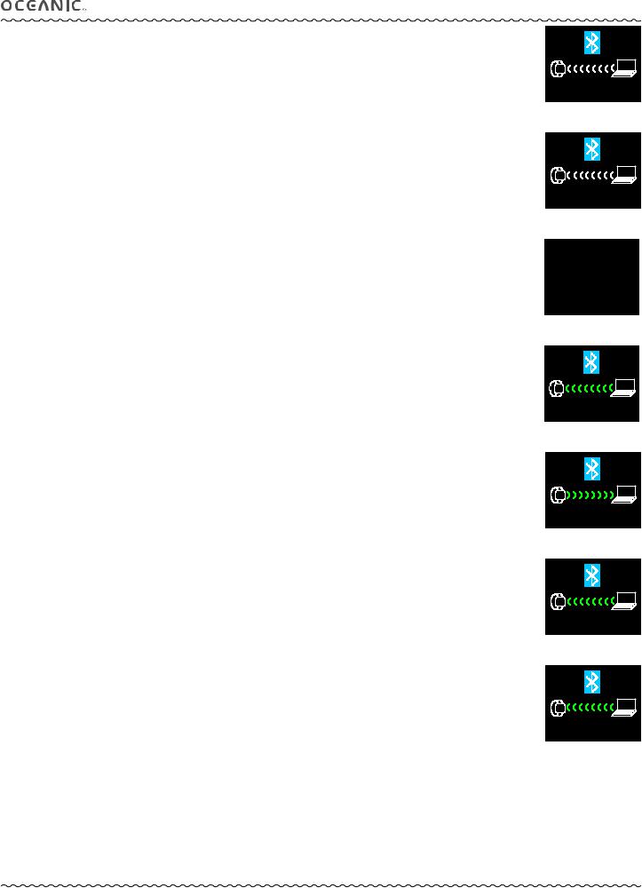
A Please Wait screen (Fig. 19A) will be displayed for 5 seconds followed by a screen displaying a countdown from 120 to 0 seconds (Fig. 19B).
If Bluetooth fails to initialize, a message will be displayed for 3 seconds instead of the countdown (Fig. 19C), then operation will revert to the Home Setup Menu.
During the countdown, the unit is on allowing it to be paired with other Bluetooth devices.
> Mobile devices require Diverlog for Mac software that contains files required to discover and communicate with the Bluetooth chip in the VTX. Likewise, laptops and desktops are only able to discover the VTX through Diverlog for Mac or the OceanLog PC Interface program with the use of an optional dongle that can be obtained from an Oceanic Dealer.
> Once paired, a connected message is displayed (Fig. 19D) with the signal icons <<<< changing from white to green while the Download, Upload, or Firmware Update operation is started.
> Once the VTX is unpaired from the PC, Mac, or mobile device, it will be necessary to pair/connect it through the software before every download/upload.
> Pairing/connecting is not permanent and needs to be reestablished every time.
> This connection functions the same way the USB does in the Diverlog and OceanLog programs.
> If the 2 minute countdown elapses without action, operation will revert to the Home Setup Menu and the connection request of the OceanLog, Diverlog, or iPhone/iPad version software will be cancelled.
> If the connection is cut using the software, operation will revert to the Home Setup Menu.
While downloading data, uploading settings, and updating firmware, corresponding screens are displayed indicating action in progress (Fig. 19E, 19F, 19G).
---------------------------------------------------------------------------------------------------------------------------
---------------------------------------------------------------------------------------------------------------------------
DC |
PC |
|
PLEASE WAIT...
Fig. 19A - BLUETOOTH
(initializing)
DC |
PC |
|
119 SECONDS
Fig. 19B - BLUETOOTH
(countdown for pairing)
WAIT WHILE
BLUETOOTH
DEACTIVATES
Fig. 19C - BLUETOOTH
(failed to initialize)
DC |
PC |
|
CONNECTED
Fig. 19D - BLUETOOTH (ready to start operation)
DC |
PC |
|
DOWNLOADING
Fig. 19E - BLUETOOTH
(in progress)
DC |
PC |
|
UPLOADING
Fig. 19F - BLUETOOTH
(in progress)
DC |
PC |
|
UPDATING FIRMWARE WAIT FOR PC MESSAGE
Fig. 19G - BLUETOOTH
(failed to initialize)
© 2002 Design, 2014 |
14 |
Doc. No. 12-5382-r01 (10/24/14) |

|
|
|
VTX OPERATING MANUAL |
|||||
|
|
|
||||||
LOG MODE (NORM/GAUG) |
|
LOG ENTRY FINDER |
||||||
Information from the latest 24 NORM and/or GAUG dives is stored for viewing. After exceeding 24 dives, the most recent dive |
|
NONE |
|
|||||
is stored while the oldest is deleted. |
|
|
||||||
> |
Dives are numbered from 1 to 24 starting each time NORM (or GAUG) mode is activated. After 24 hours elapse with no |
|
YET |
|
||||
|
|
|
|
|||||
|
dive, the first dive of the next period of operation is #1. |
|
|
|
|
|||
> |
10 minutes after a dive, the Log screens for all dives stored can be viewed. |
|
Fig. 20A - LOG MODE |
|||||
|
|
|
|
|
||||
If a dive’s elapsed time (EDT) exceeds 9:59 (hr:min), data at the 9:59 interval is recorded in the Log upon surfacing of the unit. |
|
(no dives recorded yet) |
||||||
|
|
|
|
|||||
|
|
|
|
|
|
|||
Screen sequence = Log Entry Finder (index) >> Data 1 >> Data 2 >> Data 3. |
|
LOG ENTRY FINDER |
||||||
|
2 - 4 . 9 . 14 |
# 2 |
||||||
|
|
|
|
|
||||
Prior to any dives being recorded (new unit out of the box), the graphics NONE YET are displayed (Fig. 20A) on the Log Entry |
|
1 - 4 . 9 . 14 |
# 1 |
|||||
|
99 - 10 . 29 . 13 # 22 |
|||||||
Finder screen when the Log Mode is accessed from the Home Menu by S (< 2 sec). |
|
98 - 10 . 29 . 13 # 21 |
||||||
|
|
|
|
|
97 - 10 . 28 . 13 # 20 |
|||
• S (2 sec) - to revert to the Home Menu. |
|
96 - 10 . 28 . 13 # 19 |
||||||
|
95 - 10 . 27 . 13 # 18 |
|||||||
Log Entry Finder, information includes 3 columns (Fig. 20B): |
|
Fig. 20B - LOG FINDER |
||||||
(locate dives by entry & date) |
||||||||
> Entry number - 1 to 99, most recent first (at top). |
|
|
|
|
||||
> Date of the dive. |
|
LOG ENTRY 21 - DATA 1 |
||||||
> Dive # for that day, or that series of repetitive dives. |
|
TYPE = NO DECO |
||||||
|
|
|
|
|
ELEV = SEA |
|||
|
The down arrow on the scroll bar at the right will be green if additional entries are listed going down and grey if there are |
|
PRE DIVE SI = 1:28 |
|||||
|
|
START TIME = 10:24AM |
||||||
|
no more entries. The up arrow will be green if additional entries are listed going up and grey if there are no more entries. |
|
DIVE TIME = 0:48 |
|||||
|
|
|
|
|
MAX DEPTH = 108 FT |
|||
• A (hold) - to scroll forward (down) through the listing at a rate of 8 entries per second. |
|
MIN TEMP = 59 F |
||||||
• A (< 2 sec) - to step forward (down) through the listing. |
|
Fig. 20C - LOG DATA 1 |
||||||
• M (< 2 sec) - to step back (up) through the listing. |
|
(NORM Dive) |
|
|||||
• S (< 2 sec) - to access that dive's Log Data 1 screen (for the dive highlighted). |
LOG ENTRY 99 - DATA 1 |
|||||||
• S (2 sec) - to revert to Home Menu. |
||||||||
|
TYPE = GAUG |
|||||||
|
|
|
|
|
||||
Log Data 1, information includes (Fig. 20C, 20D): |
|
ELEV = EL2 |
||||||
|
PRE DIVE SI = 0:54 |
|||||||
> Log Entry # (the # shown in the screen title matches the dive selected from the Finder listing). |
|
START TIME = 7:38AM |
||||||
> |
TYPE = NO DECO (or DECO, or VIOLA, or GAUG). |
|
DIVE TIME = 1:06 |
|||||
|
MAX DEPTH = 213 FT |
|||||||
> |
ELEV = SEA (or EL 2 to EL 7). Altitude level of the dive. |
|
||||||
|
MIN TEMP = 48 F |
|||||||
> PRE DIVE SI = hr:min. Surface Interval time before the dive. |
|
Fig. 20D - LOG DATA 1 |
||||||
> START TIME = hr:min. |
|
|||||||
|
(GAUG Dived) |
|||||||
> DIVE TIME = hr:min. Elapsed time of the dive. |
|
|
|
|
||||
> |
MAX DEPTH = xxx FT (or xx.x M). Maximum recorded during that dive. |
|
LOG ENTRY 21 - DATA 2 |
|||||
> |
MIN TEMP = xx F (or C). Minimum recorded during that dive. |
|
LAST GAS = 80%, 1.60 |
|||||
|
|
|
|
|
AV DEPTH = 56 FT |
|||
• S (< 2 sec) - to access that dive's Log Data 2 screen. |
|
AV TEMP = 60 F |
||||||
|
START = |
3000 PSI |
||||||
• S (2 sec) - to step back to the Finder screen with that dive highlighted. |
|
END = |
320 PSI |
|||||
|
|
|
|
|
MAX PO2 = |
1.02 |
||
Log Data 2, information includes (Fig. 20E, 20F): |
|
O2SAT = |
23% |
|||||
|
Fig. 20E - LOG DATA 2 |
|||||||
> Log Entry # (the # shown in the screen title matches the dive selected from the Finder listing). |
|
|||||||
|
(NORM Dive) |
|
||||||
> LAST GAS = AIR; or FO2, PO2 Alarm settings. For the last gas used during that dive. Blank if a GAUG dive. |
|
|
||||||
|
|
|
|
|||||
> AV DEPTH = xxx FT (or xx.x M). Average for that dive. |
LOG ENTRY 99 - DATA 2 |
|||||||
> AV TEMP = xx F (or C). Average for that dive. |
||||||||
|
|
|
|
|||||
> |
START = |
xxxx PSI (or xxx BAR). Tank 1 pressure when the dive started. |
|
AV DEPTH = 56 FT |
||||
> |
END = |
xxxx PSI (or xxx BAR). Pressure of the tank in use when the dive ended. |
|
AV TEMP = 60 F |
|
|||
> MAX PO2 = x.xx. Highest level reached during that dive. Blank if an Air or GAUG dive. |
|
START = |
3000 PSI |
|||||
|
END = |
320 PSI |
||||||
> O2SAT = xx%. Level of O2 saturation when the dive ended. Blank if an Air or GAUG dive. |
|
|||||||
|
|
|
|
|||||
• S (< 2 sec) - to revert to the Finder screen with that dive highlighted. |
|
Fig. 20F - LOG DATA 2 |
||||||
• S (2 sec) - to step back to that dive's Log Data 1 screen. |
|
(Air or GAUG Dive) |
||||||
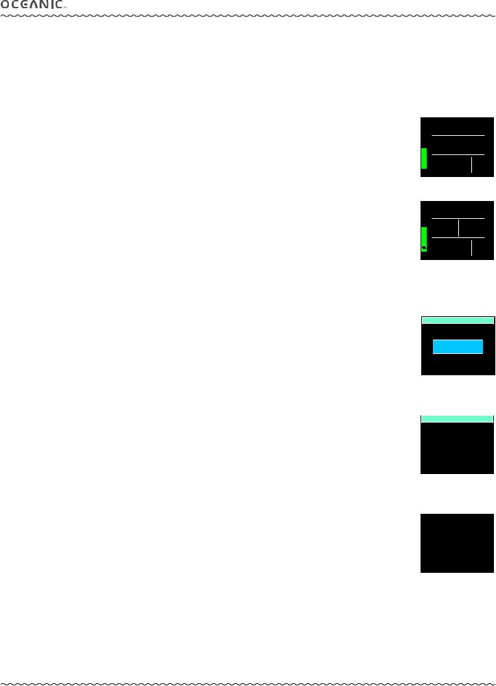
HISTORY MODE (NORM/GAUG), information includes (Fig. 21): |
|
History is a summary of data recorded during all NORM and GAUG dives conducted. |
HISTORY |
|
>TOTAL DIVES = xxxx (up to 9999).
>TOTAL HOURS = xxxx (up to 9999).
>MAX DEPTH = xxx FT (or xx.x M). Deepest depth of any dive, down to 330 FT (100 M).
>MAX EDT = x:xx (hr:min). Longest time of any dive, up to 9:59 (hr:min).
>MAX ELEV = SEA (or EL 2 to EL 7). Highest altitude level of any dive.
>LOW TEMP = xx F (or C). Lowest recorded during any dive.
TOTAL DIVES = 49 TOTAL HOURS = 38
MAX DEPTH = 139 FT
MAX EDT = 1:16
MAX ELEV = EL2
LOW TEMP = 49 F
Fig. 21 - HISTORY MODE
(cumulative summary)
• S (2 sec) - to step back to the Home Menu.
© 2002 Design, 2014 |
15 |
Doc. No. 12-5382-r01 (10/24/14) |

VTX OPERATING MANUAL
NORM
SURFACE MODE
© 2002 Design, 2014 |
16 |
Doc. No. 12-5382-r01 (10/24/14) |
VTX OPERATING MANUAL
NORM SURFACE MODE
Upon access to NORM mode, the Surface Main screen will be displayed during which time the unit will enter Dive Mode upon descent to 5 FT (1.5 M) for 5 seconds.
If 2 minutes elapse with no button action, operation will enter Power Saver Mode turning the screen off until a button is pressed. |
|
The unit will enter Post Dive Surface Mode upon ascent to 2 FT (0.6 M) for 1 second and display the Surface Main with the SURF |
|
icon flashing. |
|
Access to Alternate screens is allowed during the first 10 minutes with access to other surface modes/screens blocked until |
|
10 minutes elapse. Exception is for Violations. |
|
When the 10 minute post dive surface Interval time has elapsed, access to other Surface modes/screens is allowed. |
SURF 2:48 |
NORM SURF MAIN, information includes (Fig. 22A/B):
>Surface Interval Time (hr:min, colon flashing), with SURF icon (flashing during the first 10 minutes after surfacing).
>Graphic NORM; or NDC as 3 dashes ( - : - - ) & EDT (hr:min) with icons during the first 10 minutes after surfacing.
>Graphic GAS 1 (start Gas & default 10 minutes after a dive), Gas in use during the first 10 minutes after surfacing.
>Tank 1 Pressure with PSI (or BAR) icon (start TMT & default TMT 10 minutes after a dive), graphic SPG (meaning Submersible Pressure Gauge) if no TMT is in use; TMT in use during first 10 min after surfacing.
>Graphic DIVE with number of that dive (up to 24), 0 if no dive yet (or 2 dashes - - with GTR icon during the first 10 minutes after surfacing).
>TLBG, if any after a NORM or FREE dive.
>Low Battery icon - yellow (if voltage is at the warning level), or red flashing (if voltage is at the alarm level).
•A (2 sec) - to access the Adjust Brightness screen.
•A (< 2 sec) - to access NORM SURF ALT 1.
•M (2 sec) - to revert to the Home Menu.
•M (< 2 sec) - to access the NORM Menu.
•S (2 sec) - to access the Compass OP Main.
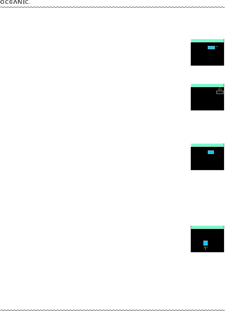
ADJUST BRIGHTNESS, information includes (Fig. 23):
> xx % (last value saved). Up to 60% max when Low Battery Warning or Alarm.
•S (2 sec) - to step back to the SURF MAIN without changing the value.
•A (< 2 sec) - to step upward through values of 10% to 100% one at a time in increments of 10%.
•M (< 2 sec) - to step down through values one at a time.
•S (< 2 sec) - to save the % setting and revert to the SURF MAIN.
NORM SURF ALT 1, information includes (Fig. 24):
>LAST DIVE (screen title).
>xxx FT (or xx.x M) with graphic MAX DEPTH.
>Elapsed Dive Time (hr:min, up to 9:59) with graphic DIVE TIME.
NORM
GAS 1 |
DIVE |
TL 850PSI |
3 |
Fig. 22A - NORM SURF MAIN
(2 hours after dive 3)
SURF 0: 04
NDC |
EDT |
- : - - 0:32 |
|
GAS 1 |
GTR |
1799PSI - - |
|
Fig. 22B - NORM SURF MAIN
(< 10 min after surfacing)
ADJUST BRIGHTNESS

 20%
20% 

Fig. 23 - Brightness
Control
•A (< 2 sec) - to access SURF ALT 2.
•M (< 2 sec) - to step back to the SURF MAIN.
•10 sec with no button action, revert to the SURF MAIN.
NORM SURF ALT 2, information includes (Fig. 25):
>DATE = m.d.y (or d.m.y).
>TIME = hr:min with AM (or PM) if 12 Hour Format.
>TEMP = xx F (or C).
>ELEV = SEA (or EL2 to EL7).
>FLY = hr:min*
>DESAT = hr:min**
>O2 SAT = xx%.
>GAS 1 = AIR; or xx%, x.xx (FO2, PO2 set).
•A (< 2 sec) - to revert to SURF MAIN.
•M (< 2 sec) - to step back to SURF ALT 1.
•10 sec with no button action, revert to SURF MAIN.
LAST DIVE
MAX DEPTH = 120 FT
DIVE TIME = 0:49
Fig. 24 - NORM SURF ALT 1
DATE = 7.30.14 TIME = 7:45 AM TEMP = 83 F ELEVSHORTCUT= SEA
FLY = 7:28 DESAT = 1:06
GAS 1 = 32%, 1.40 O2 SAT = 36%
Fig. 25 - NORM SURF ALT 2
*The Time to Fly counter will begin counting down from 23:50 to 0:00 (hr:min) 10 minutes after surfacing from any dive.
**The Time to Desaturate counter provides calculated time for Tissue Desatuation at sea level taking into consideration the Conservation Factor setting. It will begin counting down 10 minutes after surfacing from a NORM or FREE dive, counting down from a maximum of 23:50 to 0:00 (hr:min).
Desaturation requiring times greater than 24 hours will display the graphic > 24:00. In the event that Time to Desaturate still remains at the end of 24 hours, the unit will turn Off and any Ni-O2 calculations will clear.
© 2002 Design, 2014 |
17 |
Doc. No. 12-5382-r01 (10/24/14) |

|
VTX OPERATING MANUAL |
|
NORM MENU, information includes (Fig. 26): |
NORM MENU |
|
> PLAN - to view a sequence of allowed depths with no deco times. |
PLAN |
|
> SET GAS - to access a menu for setting FO2 and PO2 alarms for each gas. |
SET GAS |
|
> SET TMTS - to access a menu for setting transmitters. |
SET TMTS |
|
SET ALARMS |
||
> SET ALARMS - to access a menu for setting dive alarms. |
||
SET UTILITIES |
||
> SET UTILITIES - to access a menu for setting dive related functions such as algorithm, stops, etc. |
SET PREVIEW |
|
> SET PREVIEW - to access a menu for selecting dive related settings to be viewed together. |
VIEW PREVIEW |
|
|
||
> VIEW PREVIEW - to view items selected. |
Fig. 26 - NORM MENU |
•A (< 2 sec) - to step forward (down screen) through Menu selections (the active item highlighted).
•M (< 2 sec) - to step back (up screen) through Menu selections.
•S (< 2 sec) - to access the selection that is highlighted.
•M or S (2 sec) - to step back from the Menu to the NORM SURF MAIN.
•M (2 sec) - to exit the Menu system and revert to the NORM SURF MAIN.
•No button action (for 2 min) - will exit the Menu system and revert to the NORM SURF MAIN.
NORM PLAN MODE
No Deco time Limits (NDLs) and O2 time Limits (OTLs) in Plan Mode are based on the Algorithm selected (DSAT or Z+), the FO2 set for Gas 1, and residual nitrogen (or O2) remaining from previous NORM (or FREE) dives. FO2 set for other Gases are not used for Plan calculations.
PDPS (Pre Dive Planning Sequence)
Plan screens will sequence through Depths from 30 to 190 FT (9 to 57 M), or the Max Depth that will allow theoretical No Deco Dive Time of at least 1 minute based upon the previous dive profiles in a series of repetitive dives and taking into account descent and ascent rates of 60 FPM (18 MPM).
When the Conservative Factor is set On, NDLs are reduced to the values of the next 3,000 foot (915 meter) higher Altitude. Refer to tables in back.
PLAN GAS 1, information includes (Fig. 27A/B): |
|
|
|
||
PLAN GAS 1 |
|||||
> Graphic AIR; or xx%, x.xx - xxx FT (or M) [FO2, PO2 set with the Max Depth allowed for the PO2 alarm value set]. |
|
AIR |
|
|
|
> Plan Depth value with FT (or M) icon. |
30 FT |
4:20 |
NDL |
|
|
|
|
||||
> Dive Time allowed (hr:min) with graphic NDL (or OTL if O2 control). |
40 FT |
2:17 |
NDL |
|
|
50 FT |
1:21 |
NDL |
|
|
|
|
|
|
|||
• A (hold) - to scroll 8/sec (down screen) through the available Plan Depths from 30 to 190 FT (9 to 57 M) in increments of |
60 FT |
0:57 |
NDL |
|
|
70 FT |
0:40 |
NDL |
|
|
|
10 FT (3 M) highlighting the information one line at a time. |
80 FT |
0:30 |
NDL |
|
|
|
|
||||
|
|
||||
Fig. 27A - PDPS
The down arrow on the scroll bar at the right will be green if other deeper depths will be listed when going down and grey (Gas 1 set for Air) if there is no other depth listed below. The up arrow on the scroll bar will be green if other shallower depths will be listed
when going up and grey if there is no other depth listed above.
•A (< 2 sec) - to step forward (down) through the Plan Depths one at a time.
•M (< 2 sec) - to step back (up) through the Plan Depths one at a time.
•S (< 2 sec) - to exit the PDPS and revert to the Main Menu.
The PDPS will step/scroll to the Max Depth that will allow a theoretical No Deco time of at least 1 minute based upon previous dive profiles in a series of repetitive dives.
Once a dive is conducted, the algorithm selected will lock into that selection until 24 hours elapse on the surface after the dive, or all residual nitrogen has been offgassed (DSAT time = 0:00).
SET GAS MENU (NORM), information includes (Fig. 28A):
Selections with their last set points saved include:
>GAS 1 = with AIR; or 21 to 100% and 1.xx (PO2 alarm setting).
>GAS 2 = with OFF; or AIR; or 21 to 100% and 1.xx (PO2 alarm setting).
>GAS 3 = with OFF; or AIR; or 21 to 100% and 1.xx (PO2 alarm setting).
>GAS 4 = with OFF; or AIR; or 21 to 100% and 1.xx (PO2 alarm setting).
PLAN GAS 1
32%, 1.40 - MAX 111FT
30 FT |
9:55 |
NDL |
|
|
|
|
|
|
|
||||
40 FT |
4:22 |
NDL |
|
|
|
|
50 FT |
2:28 |
NDL |
|
|
|
|
60 FT |
1:32 |
NDL |
|
|
|
|
70 FT |
1:05 |
NDL |
|
|
|
|
80 FT |
0:49 |
NDL |
|
|
|
|
|
|
|
||||
|
|
|
|
|
|
|
Fig. 27B - PDPS (Gas 1 set for Nitrox)
SET GAS MENU
GAS 1 = AIR
GAS 2 = 22% , 1.40 GAS 3 = 32% , 1.40 GAS 4 = OFF
MAX DEPTH = 124 FT
Fig. 28A - SET GAS MENU
(Gas 2 selected)
•A (< 2 sec) - to step forward (down screen) through and highlight Menu selections.
•M (< 2 sec) - to step back (up screen) through Menu selections.
•S (< 2 sec), when a selection is highlighted - to highlight & flash* that item’s set point.
*During the time that a numeric FO2 value is flashing, the Max Depth allowed for the PO2 alarm value shown is displayed at the bottom.
FO2 set for AIR:
>The default FO2 for Gas 1 each new activation period is AIR.
>When FO2 for Gas 1 is set for AIR -
>calculations are the same as when it is set for 21% O2.
>it remains set for AIR until it is set for a Nitrox (21 to 100% O2).
>O2SAT and PO2 values and/or warnings will not be displayed at any time, on the surface or during dives.
>Max Depths allowed by the PO2 alarm set will not be displayed.
© 2002 Design, 2014 |
18 |
Doc. No. 12-5382-r01 (10/24/14) |
VTX OPERATING MANUAL
>Internally, the unit will keep track of the oxygen accumulation so that if FO2 for Gas 1 is subsequently set for Nitrox, the oxygen accumulated during previous AIR dives will be accounted for in the next Nitrox dive (during that dive period and series of repetitive dives).
FO2 set for Nitrox:
>When FO2 for any Gas is set for Nitrox (21 to 100%), the dive is calculated to be for Nitrox.
>Once FO2 for Gas 1 is set for Nitrox (21 to 100%), the AIR option for all gases is disabled until 24 hours elapse after the last dive.
> The AIR option will not be displayed in Set Gas until a full 24 hour Surface Interval has elapsed.
When the FO2 digits are highlighted & flashing (Fig. 28B):
•A (< 2 sec) - to step up through FO2 set points one at a time from AIR to 21 to 100% in increments of 1%.
•A (hold) - to scroll upward through the FO2 set points at a rate of 8 per second stopping momentarily at 32%, 50%, 80%,
and 100%, then at AIR or 21%.
•M (< 2 sec) - to step down through FO2 set points one at a time.
•S (< 2 sec) - to save the FO2 setting and highlight & flash the PO2 digits if Nitrox, or move to GAS 2 if AIR.
•S (2 sec) - to step back to & highlight the GAS # selected without changing the FO2 setting.
When the PO2 alarm digits are highlighted & flashing (Fig. 28C):
•A (< 2 sec) - to step up through the set points one at a time from 1.00 to 1.60 in increments of 0.05.
•M (< 2 sec) - to step down through the set points one at a time.
•S (< 2 sec) - to save the PO2 Alarm setting and step back to & highlight the GAS # selected.
•S (2 sec) - to step back to & highlight the FO2 value without changing the PO2 setting.
FO2 & PO2 Alarms for all gases will remain at their respective set points until changed.
SET TMT MENU (NORM, GAUG), information includes (Fig. 29A):
Selections with their last set points saved include (SET will not be displayed upon access):
>TMT 1 = with OFF or ON.
>TMT 2 = with OFF or ON.
>TMT 3 = with OFF or ON.
>TMT 4 = with OFF or ON.
•A (< 2 sec) - to step forward (down screen) through and highlight Menu selections.
•M (< 2 sec) - to step back (up screen) through Menu selections.
•S (< 2 sec), when a selection is highlighted - to highlight & flash that item’s set point.
•A (< 2 sec) - to step forward through that TMT’s set points (OFF, ON, & SET).
•M (< 2 sec) to step back through that TMT’s set points.
•S (< 2 sec) - to save the setting.
>If OFF is selected (saved), the VTX’s receiver will be disabled, all other TMT set selections will display the graphic OFF, and operation will revert to the Set Utilities Menu.
>If ON is selected, ON becomes solid and the next TMT ON/OFF set point will flash, allowing it to be set.
>If SET is selected, the Set TMT Link Code screen will be displayed.
Set TMT Link Code (Serial Number), information includes (Fig. 29B):
>Graphics TMT 1 (2, 3, 4) SERIAL NUMBER.
>6 digit serial number, the 1st (left) digit flashing.
•A (< 2 sec) - to step upward through the 1st digit’s values.
•M (< 2 sec) - to step back through the 1st digit’s values.
•S (< 2 sec) - to save the 1st digit’s value and flash the 2nd digit.
•Repeat A, M, S button action until all digits are set with operation then reverting to the Set TMT Menu with SET highlighted allowing OFF or ON to be selected.
SET GAS MENU
GAS 1 = AIR  GAS 2 = 32% , 1.40
GAS 3 = 50% , 1.40 GAS 4 = OFF
MAX DEPTH = 124 FT
Fig. 28B - SET GAS MENU
(setting Gas 2 FO2)
SET GAS MENU
GAS 1 |
= AIR |
|
GAS 2 |
= 32% , |
1.40 |
GAS 3 |
= 50% , 1.40 |
|
GAS 4 |
= OFF |
|
MAX DEPTH = 124 FT
Fig. 28C - SET GAS MENU
(setting Gas 2 PO2 Alarm)
SET TMT MENU
TMT 1 = ON
TMT 2 = SET
TMT 3 = OFF
TMT 4 = OFF
Fig. 29A - TMT SET MENU
SET TMT LINK CODE
TMT 2
SERIAL NUMBER
0 3 9 9 5 6
Fig. 29B - SET LINK CODE
© 2002 Design, 2014 |
19 |
Doc. No. 12-5382-r01 (10/24/14) |
VTX OPERATING MANUAL
SET ALARMS MENU (NORM), information includes (Fig. 30): |
|
NORM SET ALARMS |
Selections with their last Set points saved include:
>AUDIBLE = with ON or OFF.
>DEPTH = with OFF, or 30 to 330 FT (or 10 to 100 M), increments of 10 FT (3 M).
>EDT = with OFF, or 0:10 to 3:00 (hr:min), increments of :05. EDT is Elapsed Dive Time.
>TLBG = with 1 to 8 SEG, increments of 1 SEG. SEG means Segments of the bar graph
>DTR = with OFF, or 1 to 0:20 ( :min), increments of :01. DTR is Dive Time Remaining.
>TURN = with OFF, or 1000 to 3000 PSI (or 70 to 205 BAR), increments of 250 PSI (5 BAR). TURN is pressure of TMT 1.
>END = with 300 to 1500 PSI (or 20 to 105 BAR), increments of 100 PSI (5 BAR). END is pressure of the TMT in use.
•A (< 2 sec) - to step forward (down screen) through and highlight Menu selections.
•M (< 2 sec) - to step back (up screen) through Menu selections.
•S (< 2 sec), when a selection is highlighted - to highlight & flash that item’s set point.
•A (< 2 sec) - to toggle or increase the set point.
•A (hold) - to increase the set point at a rate of 8 per second.
•M (< 2 sec) - to toggle or decrease the set point.
•S (< 2 sec) - to save the setting and revert to the Set Alarms Menu.
AUDIBLE = ON
DEPTH = 130 FT
 EDT = 0:40
TLBG = 8 SEG
DTR = 0:10 TURN = 1500 PSI
END = 300 PSI
Fig. 30 - SET ALARMS
SET UTILITIES MENU (NORM), information includes (Fig. 31A):
Selections with their last Set points saved include:
>WATER = with FRESH or SEA. This adjusts depth values based on the type of water.
>UNITS = with IMPERIAL or METRIC.
>DEEP STOP = with OFF or ON. This only applies to No Deco dives.
>SAFE STOP = with OFF or ON. This only applies to No Deco dives.
>ALGORITHM = with DSAT or Z+. This determines the basis for Ni-O2 calculations.
>CONSERV = with OFF or ON. This, Conservative Factor, reduces NDLs based on altitude level.
>SAMPLING = with 2, 15, 30, or 60 SEC (second). This is the rate that data is sampoled and recorded for PC download.
NORM SET UTILITIES
WATER = FRESH UNITS = IMPERIAL
DEEP STOP = OFF SAFE STOP = ON 

ALGORITHM = DSAT
CONSERV = ON SAMPLING = 15 SEC
Fig. 31A - SET UTILITIES
Additional information relating to the effects of the items included are described in associated sections throughout this manual.
•A (< 2 sec) - to step forward (down screen) through and highlight Menu selections.
•M (< 2 sec) - to step back (up screen) through Menu selections.
•S (< 2 sec), when a selection is highlighted - to highlight & flash that item’s set point.
•A (< 2 sec) - to toggle or increase the set point.
•A (hold) - to increase the set point at a rate of 8 per second.
•M (< 2 sec) - to toggle or decrease the set point.
•S (< 2 sec) - to save the setting and revert to the Set Utilities Menu.
Set Safety Stop
In addition to OFF and ON, Safety Stop has a SET selection.
•S (< 2 sec), while SET is flashing - will display the Set Safe Stop Time/Depth screen with the Time setting flashing (Fig. 31B).
•A or M (< 2 sec) - to toggle TIME between 3 MIN and 5 MIN.
•S (< 2 sec) - to save the Time setting and flash the Depth digits.
•A (< 2 sec) - to step upward through Depth set points of 10, 15, 20 FT (or 3, 4, 5, 6 M).
•M (< 2 sec) - to step back through Depth set points.
•S (< 2 sec) - to save the setting and revert to the Set Utilities Menu with SET highlighted & flashing allowing OFF or ON to
be selected/saved (as described above).
SET PREVIEW (NORM), information includes (Fig. 32):
Using this listing, you can chose up to 7 items (set points that have been entered) for display on a Preview screen that can be accessed from the NORM Menu (see page 16).
>FO2, PO2 alarms set for - Gas 1, 2, 3, 4.
>Alarm values set for - Depth, EDT, DTR, TLBG, Turn Pressure, End Pressure.
>Water Type selected.
>Deep Stop seting.
>Safety Stop setting.
•A (< 2 sec) - to step forward (down 1st column then 2nd) through & highlight selections.
•M (< 2 sec) - to step back (up) through selections.
•S (< 2 sec) - when an item is highlighted will toggle* it between solid and flashing.
SET SAFE STOP
TIME = 3 MIN 

DEPTH = 15 FT
Fig. 31B - SET NO DECO
SAFETY STOP
NORM SET PREVIEW
GAS 1 |
TLBG AL |
GAS 2 |
WATER |
GAS 3 |
DEEP STOP |
GAS 4 |
SAFE STOP |
DEPTH AL |
TURN AL |
EDT AL |
END AL |
DTR AL |
|
Fig. 32 - SET PREVIEW
*Once 7 items are highlighted/flashing, another item cannot be toggled to be highlighted/flashing until one of the highlighted/flashing items is toggled to solid, not highlighted first.
When satisfied that those items flashing (up to 4) are what you want for the Preview screen, press S (2 sec) to display all items flashing, then press S (< 2 sec) to revert to the Menu with SET PREVIEW highlighted.
© 2002 Design, 2014 |
20 |
Doc. No. 12-5382-r01 (10/24/14) |
 Loading...