

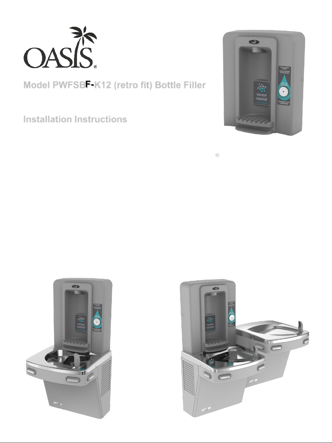
Model PWFSBF-K12 (retro fit) Bottle Filler
Installation Instructions
The Bottle Filler mounts directly above Versacooler® I and II products.
No additional electrical connections are required.
If installed onto a refrigerated cooler, then chilled water can be dispensed
through the Bottle Filler. Otherwise, room temperature water will be dispensed.
The Bottle Filler is shipped partially assembled.
When completed, the finished assembly will look like this:
OR
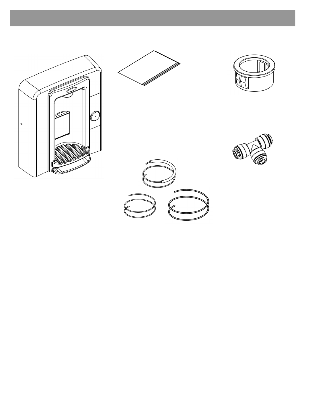
Section 1: Getting Started
What’s Included:
Installation
instructions
K-12 Bottle Filler
with filter (installed
onto the wall
frame)
Snap bushing
Quick connect
tee fitting
1. One 38” of ¼ OD plastic tubing with
14” of sponge tubing insulation.
2. One 38” of ¼ OD plastic tubing.
3. One 48” of ¼ OD plastic tubing.
Tools required:
3/8” pilot drill and either a step drill bit up to 7/8” diameter that
will drill through SS top or 7/8” diameter punch die
Small tubing cutter for copper tube
1/4 “ nut driver
#15 torx bit driver
2
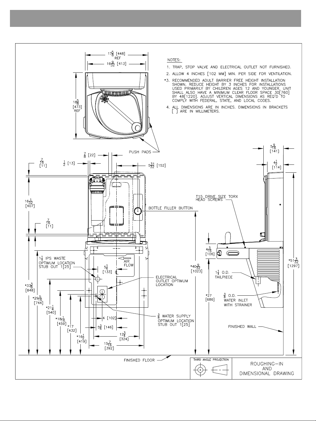
Section 2: Rough In Drawing
Oasis Versacooler® II Models PGAC, PG8AC with Bottle Filler
3
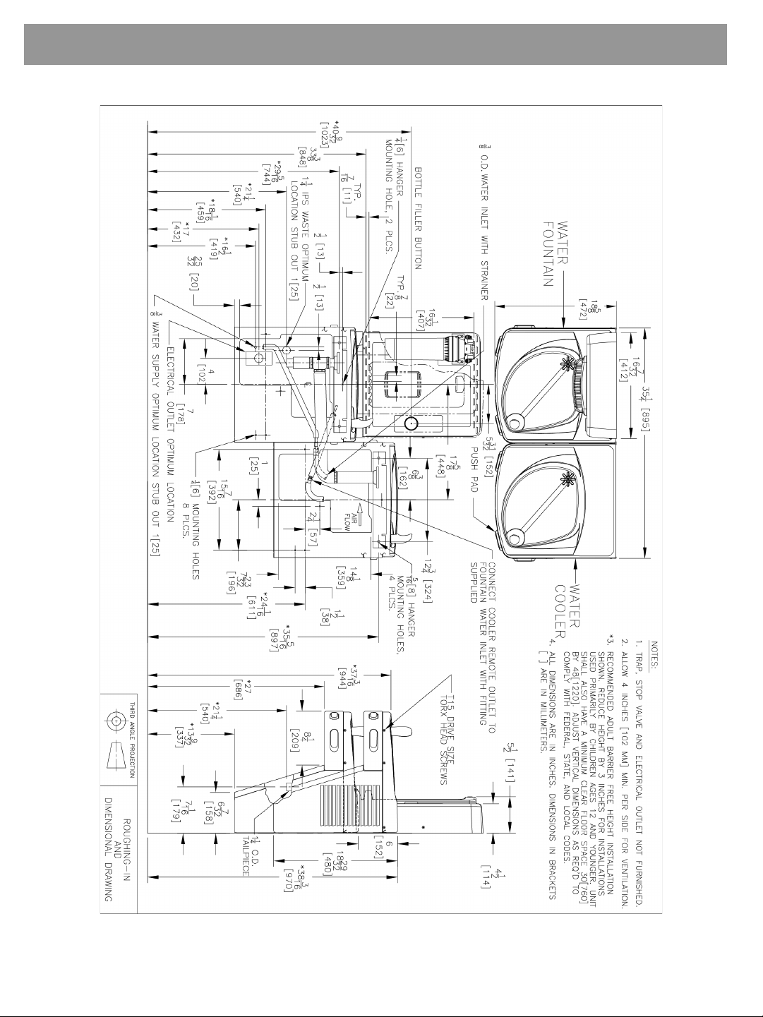
Section 2: Rough In Drawing
Oasis Versacooler® II Split Level Models with Bottle Filler
*On split level models, the Bottle Filler must be mounted on
the low unit in order to meet ADA guidelines.
4
Section 3: Installation
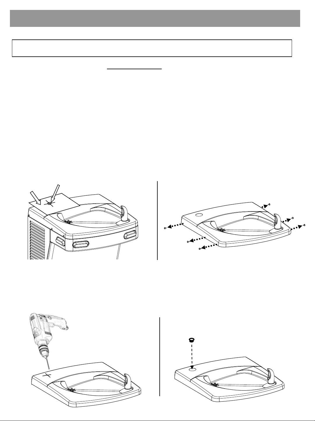
A: Drilling Hole in the Top for Water Line Connections.
1. Disconnect power by UNPLUGGING unit. It might be necessary to
remove the front panel to get access to the power.
2. Turn OFF water supply to the unit. It might be necessary to remove the
front panel to access the water stop valve.
3. Place hole template onto cooler top so it is aligned with the left side of
unit and wall. SEE NEXT PAGE FOR TEMPLATE
4. Mark hole location
5. Remove top from unit.
Mark hole location.
Template
Remove top from cooler by
removing six, #15 torx head screws
on sides of top.
6. Using a step drill bit or 7/8” punch die, make a 7/8” hole through top. You
may want to drill a pilot hole to get these started.
7. Install snap bushing into hole to protect tubing from being cut.
Install bushing
Drill
5
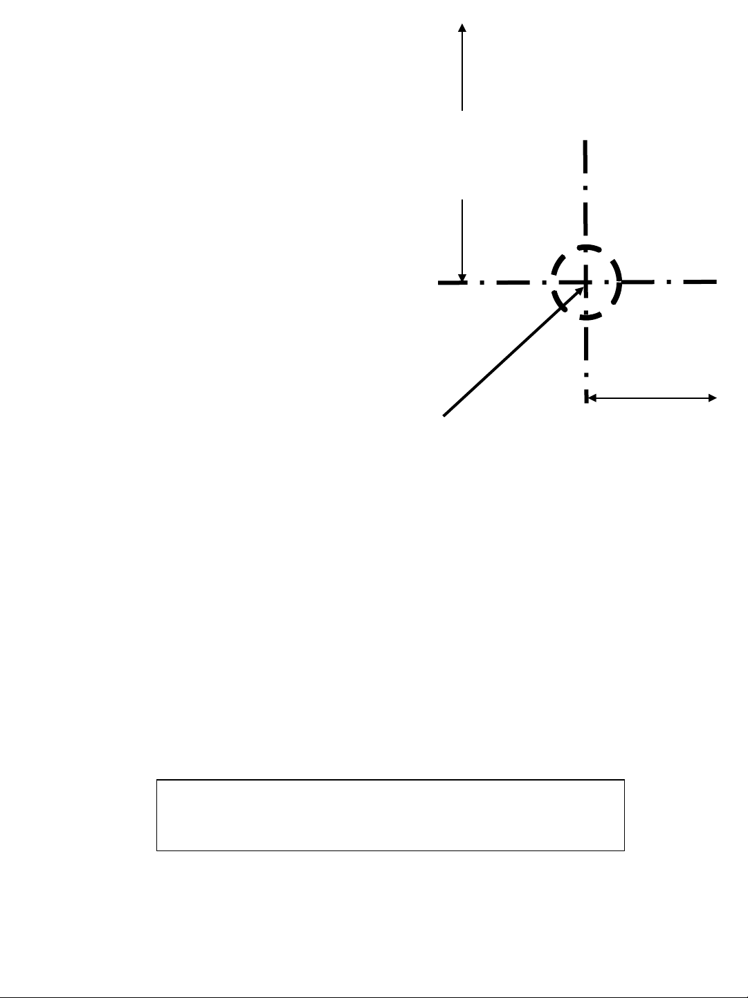
ALIGN THIS EDGE WITH LEFT EDGE OF COOLER TOP
Mark this center point on the
top. Remove the top from the
cooler. Then create a 7/8”
diameter hole through the top
3-1/4”
from
side
PLACE THIS EDGE AGAINST WALL
2-1/8”
from
back
at the marked center point
(step drill bit or punch die).
USE THIS TEMPLATE TO MARK THE
HOLE LOCATION ON COOLER TOP
6
Section 3: Installation
B: Connecting the Water Line
If the cooling tank is non-pressurized, then go to the “Pressurizing the
cooling tank” addendum section. Otherwise, proceed to step 1 below.
Non-pressurized units are single
Refer to the schematic below to identify the system that you have.
units made since December of 2009.
Water
valve/
regulator
tank
Supply
Water
Water
valve/
regulator
tank
Cooling
NON-
PRESSURIZED
COOLING TANK
Supply
Water
Cooling
PRESSURIZED
COOLING
TANK
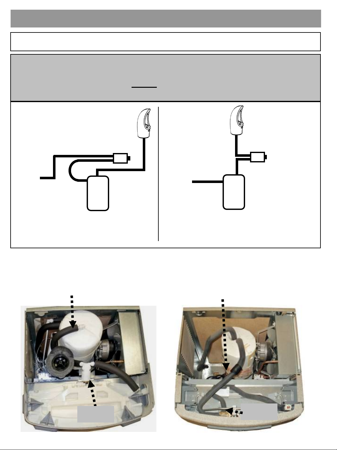
1. With the cooler top removed, find the tube going from the cooling
tank outlet to the valve. The TEE fitting (supplied) will need to
connect between the cooling tank and valve.
Outlet Tube (insulated plastic)
Outlet Tube (insulated copper)
Valve
P8AC family
Valve
P8AM family
7

Section 3: Installation: For the P8AC Version: Versacooler II
2. Disconnect tubing from the
elbow on the valve.
3. Using the 38” piece
of tubing provided,
cut 6” and install it
on the end of the
TEE. Install the
remaining tubing
onto the branch of
the TEE. Connect
the other end of the
TEE to the tank
outlet tubing (tube
that was
disconnected from
the elbow).
TEE
32” tubing
6” tubing
4. Route the TEE and
tubing under the
waste drain and
connect the 6” length
to the water valve
elbow.
Go to Step 5 “Final steps for both product families:”
Water
valve
elbow
8

Section 3: Installation: For the P8AM Version: Versacooler I
2. Remove tar tape from
the insulation on the
outlet tube.
Remove tar tape
3. Pull back insulation and cut
the copper tube with a
tubing cutter. Cut where
there is at least 1 inch of
straight tubing on each side
of the cut.
4. Install TEE fitting by
connecting the copper
tubing to each end. Then
install the 32” piece of
plastic tubing to the TEE
branch.
32” plastic
tubing
(supplied)
9

Section 3: Installation: Final steps for both product families:
5. Feed tubing up through the top and attach the
top to the cooler.
To activation cartridge inlet.
TIP: For the P8AM, it is easier to
connect the outlet tube to the bubbler if
the front nose is removed.
10

Section 3: Installation
C: Mounting the frame to the wall
1. Set the wall frame onto the top. Center it left/right and push it against the
wall and mark hole locations for wall fasteners. The rubber feet will set the
frame at the proper height.
Use mounting slots that will
provide the proper securing
Make sure to pull
the plastic tubing
up through the hole
in the frame.
location.
2. Secure frame to the wall with fasteners (not provided). Pull plastic
tubing up through the hole in the frame.
11

Section 3: Installation
D: Bottle Filler Plumbing Connections
3.1. Install water line tubing as shown below.
ATTENTION: Shut off water and relieve water pressure through bubbler.
Supply water line In
Filtered water out
to cold tank
48” (trim excess)
Cold water out with
sponge tubing to
activation cartridge
inlet.
38”
Activation
Cartridge
Cold water out
of cooling tank.
Cut cold water out
tubing and insert tee
fitting before valve
cartridge holder inlet.
(Tee was installed per
Section 3B:
Connecting the water
line)
Front view of
cooler & bottle
filler.
12

Section 3: Installation
3.2. Install water line tubing as shown below.
ATTENTION: Shut off water and relieve water pressure through bubbler.
Filtered water out to cold tank
48” (trim excess)
Supply water
line In
Cold water out with
sponge tubing to
activation cartridge
inlet.
38”
Activation
Cartridge
Cold water out
(existing)
Cut cold water out tubing and
insert tee fitting before valve
cartridge holder inlet. (Tee
was installed per Section 3B:
Connecting the water line)
Front view of
cooler & bottle
filler.
13

Section 3: Installation
E: Attaching the Tether
4. Install bottle filler tether with the steps below.
Attach the tether line assembled to the bottle
filler dispense bracket to the cleat on the
mounting frame.
1.
Push loop through hole.
3.
2.
Put loop around one side
of the cleat.
4.
Pull loop around other
side of the cleat.
Pull tight.
14

Section 3: Installation
The tether keeps the bottle filler secured to the frame when changing the
filter. Make sure the tether is installed properly to avoid accidental
damage to the unit.
15

Section 3: Installation
F: Attaching Bottle Filler to Frame
5. Set the Bottle Filler cabinet into place.
6. Attach Bottle Filler assembly to the frame using the two (2) torx screws.
Torx screw
Torx screw
16

Section 3: Installation
G: Installation Completion
7. Turn ON water supply and check for leaks. Press the activation button
and release any trapped air from the system. Plug in the power cord and
replace the front panel IF it was removed earlier. Flush out filter as
directed on the filter cartridge label.
Press
INSTALLATION COMPLETE
17

Addendum Section: Pressurizing Cooling Tank
The water should
already be turned OFF
and the power
disconnected.
Unit as it appears with top
removed
STEP 1
Unplug un-insulated water
line from water valve inlet
(JG elbow located left side
of water valve facing the
front of the cooler). Set
tubing aside (careful to not
contaminate water contact
end).
STEP 2
Unplug tubing from JG
elbow leading to
cooling tank inlet.
18

STEP 3
Plug un-insulated tubing that
was removed in step 1 into
JG elbow leading to the
cooling tank from step 2.
STEP 4
Unplug tubing that is
connected to the
water valve outlet (JG
elbow located on the
right side of valve
facing the cooler).
STEP 5
Connect tubing
from step 4 to JG
elbow on the left
side of the valve.
19

Step 6
Unplug JG tubing
from the cooling
tank outlet. Do
not set it down.
Step 7
Using tubing
removed in step 6,
plug into JG elbow
on the right side of
the valve. (be sure
to rout the tubing
under existing
tubing installed in
step 4 as shown)
Step 8
Using tubing that is
connected to the JG
elbow left side of
valve (done in step
4), and plug the
other end to the JG
fitting at the top of
the cooling tank.
20
Return to Section 3 B
“Connecting the water line”

EXPLODED PARTS
ITEM QTY P/N Description ITEM QTY P/N Description
1 1 041080-001 CABINET, K12 BF 20 2 029994-103 FTG, PP ELBOW, PLUG IN
2 1 036790-001 BADGE, OASIS SMALL OVAL 21 4 026630-022 SCREW, PAN HD TAPPING #10
3 1 038031-009 LABEL, CABINET BUTTON 22 1 041072-001 FILTER HEAD, VERSAFILTER II
4 2 026642-023 SCREW, HEX HD TAPPING #8 23 2 026642-004 SCREW, HEX HD TAPPING #8
5 1 038031-010 LABEL, ALCOVE SBF K12 24 1 041073-001 BRKT, VERSAFILTER II
6 2 031875-003 SCREW, TRUSS HD TAPPING TORX 25 1 041071-001 FILTER, VERSAFILTER II
7 1 038636-001 PUSH BUTTON, AMC 26 2 041079-001 FOOT, RUBBER
8 1 038678-001 PLUG, BUTTON 27 2 026630-076 SCREW, PAN HD TAPPING #8
9 1 035990-001 HOLDER, CARTRIDGE STEM CON 28 38" 029959-006 TUBING, PE 1/4 OD WHITE
10 1 A020957 NUT, RETAINING PLASTIC 29 48" 029959-006 TUBING, PE 1/4 OD WHITE
11 1 029967-005 CARTRIDGE, 4.25# SPRNG 30 1 041076-001 BRKT, DISPENSE NOZZLE
12 2 026670-008 SCREW, HEX HD MACHINE #10 31 1 032459P008 LANYARD, BOTTLE FILLER
13 1 041075-001 BRKT, CARTRIDGE VALVE 32 2 031875-003 SCREW, TRUSS HD TAPPING TORX
14 11'' 028476-001 INSULATION, SPONGE TUBING 33 1 038032-001 FLOW NOZZLE ASSY
15 12" 029959-006 TUBING, PE 1/4 OD WHITE 34 1 038029-001 ADAPTER, FLOW NOZZLE
16 2 028481-101 FTG, PP UNION ELBOW WHT 35 1 028482-001 FTG, JG REDUC IN G ELBOW
17 38" 029959-006 TUBING, PE 1/4 OD WHITE 36 2 026642-003 SCREW, HEX HD TAPPING #8
18 14" 028476-001 INSULATION, SPONGE TUBING 37 1 027189-008 BUSHING, SNAP 7/8"
19 1 036687-003 FRAME, PWFSBF-K12 38 1 029199-103 FTG, PP UNION TEE WHITE
BREAKDOWN
P/N 030099-596 Date: 3/2019
© 2019 LVD Acquisition, LLC
Oasis, Versacooler are registered trademarks of LVD Acquisition, LLC.
Oasis International
222 East Campus View Blvd.
Columbus, OH 43235
614-861-1350
www.oasiscoolers.com
21
 Loading...