

Oakton Salt 6 Instruction Manual

gyM
sy...
Instruction Manual
Salt 6
Hand-held Salinity Meter
Tech nol o
adeEa
68X243619
ver. 0 051102

Preface
This manual serves to explain the use of the Salt 6 salinity meter.
It functions in two ways: first as a step by step guide to help you operate the
meter; second, it serves as a handy reference guide.
This manual is written to cover as many anticipated applications of the Salt 6
salinity meter as possible. If there are doubts in the use of this meter, please do
not hesitate to contact the nearest Eutech Instruments/ Oakton Instruments
Authorized Distributor.
Eutech Instruments/ Oakton Instruments will not accept any responsibility for
damage or malfunction to the meter caused by improper use of the instrument.
The information presented in this manual is subjected to change without notice
as improvements are made, and does not represent a commitment on the part
of Eutech Instruments Pte Ltd/ Oakton Instruments.
Copyright © 2002
Eutech Instruments Pte Ltd/ Oakton Instruments
All rights reserved. Version 0, 051102.

TABLE OF CONTENTS
1 INTRODUCTION 1
2 DISPLAY & KEYPAD FUNCTIONS 3
2.1 Display 3
2.2 Keypad 4
3 PREPARATION 5
3.1 Inserting & Removing Rubber Boot 5
3.2 Inserting the Batteries 5
3.3 Battery Replacement 6
3.4 Conductivity Electrode Information 6
3.5 Connecting the Probe to Meter 8
3.6 Switching the Meter On 9
3.7 Change Salinity ÙTemperature Measurement Mode 10
4 CALIBRATION 11
4.1 Important Information on Meter Calibration 11
4.2 Preparing the Meter for Calibration 12
4.3 Calibration for Salinity (% or ppt) 13
4.4 Temperature Calibration 14
5 MEASUREMENT 15
5.1 With Automatic Temperature Compensation (ATC) 15
5.2 Without ATC (Manual Temperature Compensation) 16
5.3 Taking Measurements 17
5.4 HOLD Function 18
6 ADVANCED SETUP FUNCTIONS 19
6.1 Advanced Setup Overview 19
6.2 Temperature Coefficient 21
6.3 Normalization Temperature 22
6.4 Selection of ppt or PrSn. (Default being PrSn) 23
6.5 Restore Factory Default Values 24
7 PROBE CARE AND MAINTENANCE 25
8 TROUBLE-SHOOTING GUIDE 26
9 ERROR MESSAGES 27
10 SPECIFICATIONS 29
11 ACCESSORIES 30
12 ADDENDUM 1: CALIBRATION TIPS 31
13 WARRANTY 32
14 RETURN OF ITEMS 33

Instruction Manual Salt 6
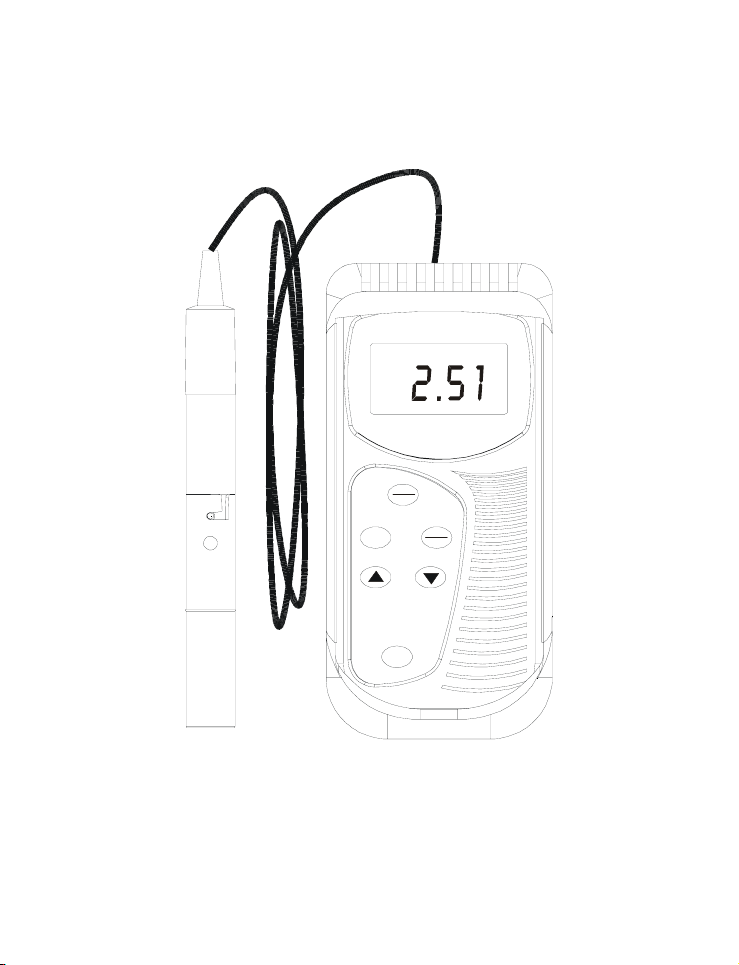
1 INTRODUCTION
Thank you for purchasing the Salt 6 Salinity meter. These economy
microprocessor-based handheld meters deliver up to ±0.5% full-scale accuracy.
It has a large custom LCD (Liquid Crystal Display) for clear and easy reading.
The Salt 6 meter measures the amount of Sodium Chloride (NaCl)
concentration either in Percentage (%) or Parts Per Thousand (ppt), and
Temperature (°C).
Your meter includes a conductivity electrode (cell constant K = 1.0) with built-in
temperature sensor (Order Code: EC-CONSEN91B/ 35606-55), a rubber boot,
4 alkaline “AAA” batteries, instruction manual and warranty card.
Please read this manual thoroughly before operating your meter.
To order other accessories and buffer standard solutions, please refer to the
Accessories Section for more information.
1
Instruction Manual Salt 6
Salt
6
%
Salinity Meter
ON
OFF
MODE
HOLD
ENTER
CAL
2

Instruction Manual Salt 6
2 DISPLAY & KEYPAD FUNCTIONS
2.1 Display
The meter has a large custom LCD that consists of 4-digit segments and
operation annunciators for ppt or %, and °C (Temperature). Other annunciators
include “HO” (when the HOLD function is activated) and “LO” (low battery
condition).
56
HO LO
1
LCD and Customized Annunciators for Salt 6 salinity meter
1. Primary display 4. Percentage indicator for
2. Parts Per Thousand (ppt) 5. Low battery indicator.
3. Temperature indicator 6. Hold (freezed) reading
3
4
%
C°
ppt
Concentration and
Temperature Coefficient.
indicator.
3
2

Instruction Manual Salt 6
2.2 Keypad
The Salt 6 salinity meter has 6 keys on its splash-proof keypad; ON/OFF,
HOLD/ENTER CAL, MODE, ▲ and ▼ keys. Some buttons have several
functions depending on its mode of operation.
ON
OFF
CAL
HOLD
ENTER
MODE
• Powers on and shuts off the meter. Takes you directly into
measurement mode when meter is switched on.
• Enters into calibration mode for % (or ppt) and Temperature.
• To abort calibration or setup mode without confirming any set
value.
HOLD: Freezes the measured reading. To activate, press HOLD
key while in measurement mode. To release, press HOLD
key again.
ENTER: Press to confirm values in calibration mode, and to confirm
selections in SETUP mode.
• In Calibration Mode: Press to scroll through calibration values.
• In Setup Mode: Press to scroll through the setup sub-group
programmes.
• Selects measurement mode for salinity and Temperature.
• When pressed together with ON/OFF key, it will take you into
the SETUP mode. This allows you to customize meter
preferences such as selecting electrode’s normalization
temperature, temperature coefficient factor, and resetting the
meter to factory default.
1) Normalization Temperature
2) Temperature Coefficient Factor
3) Selection of ppt or % measurement mode (ppt or PrSn
4) User reset
4

Instruction Manual Salt 6
3 PREPARATION
3.1 Inserting & Removing Rubber Boot
1) To remove meter from rubber boot, push
out from the bottom edges of meter until it
is completely out of boot. Ensure that the
cables of Conductivity electrode or
temperature probe are not connected.
2) To insert meter into rubber boot, slide in
from the top of meter before pushing the
bottom edges of meter down to set it into
position. Lift up the stand at the back of
meter for bench top applications if
necessary.
3.2 Inserting the Batteries
The battery compartment is found at the
back of instrument as shown. To open the
battery compartment:
3) Push in the direction of arrow
and lift up the cover.
4) Note the polarity of battery
before inserting into position.
5) After replacement, place cover
back and press down until it
locks tight.
5

Instruction Manual Salt 6
3.3 Battery Replacement
A “LO” annunciator in the LCD alerts you when battery power is running low.
Replace with the same type as recommended by the manufacturer.
LO
"LO" Battery Condition
Caution: Power off the meter when changing battery.
%
3.4 Conductivity Electrode Information
The Salt 6 salinity hand-held meter is supplied with a
electrode with a BNC connector. This electrode (Order
Part Number: EC-CONSEN91B/ 35606-55) comes with
Stainless Steel rings, cell constant of K = 1.0, and a builtin temperature sensor for Automatic Temperature
Compensation (ATC). Its specially designed Ultem-body
housing has good chemical resistant properties. It
provides fast temperature response and reduces air
entrapment, which makes it easy to obtain accurate,
stable readings.
The probe materials used which have good chemical
durability include:
1. Polyetherimide (Ultem) – protective probe guard
2. Polybutylterphalate (Valox) – sensor housing
3. Stainless Steel (SS 304) – 2 steel bands
6
Instruction Manual Salt 6
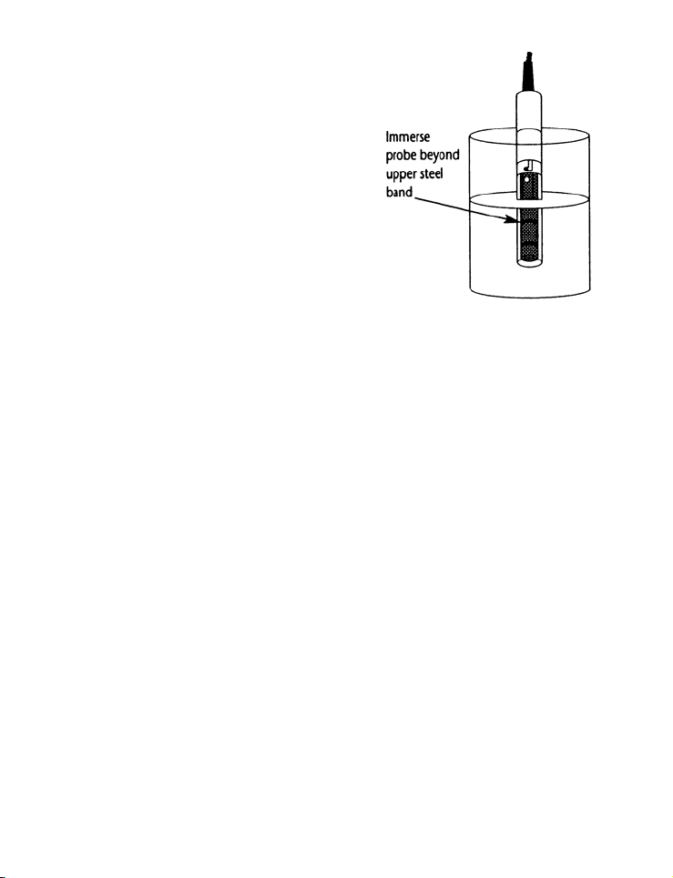
Proper use of probe is essential to ensure
that the optimum measurement is taken in
a short time.
The removable protective plastic probe
guard is meant for simple periodic
maintenance and it must be kept in tact
during measurement and calibration.
Always immerse the probe beyond upper
steel band.
NOTE:
1) DO NOT remove the protective probe guard during measurement
and calibration as it may affect your readings.
2) We recommend that you do not submerge the probe above the
protective guard. You can submerge the cable for brief periods of
time, but not continuously.
See Section 7 - Probe Care and Maintenance” for more information.
7
Instruction Manual Salt 6
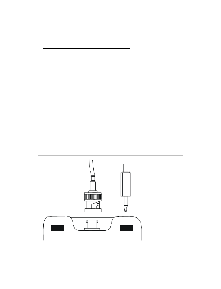
3.5 Connecting the Probe to Meter
1) To connect electrode into meter, align the connector slots with the
posts of meter’s socket and rotate connector clockwise until it locks.
2) To remove, simply rotate the connector in anti-clockwise direction
until it unlocks, and slide the connector off the socket.
3) Insert the mini phono jack of temperature sensor into the socket on
the meter as shown in Figure below.
4) Unplug the phono jack when not in use or when you want to
measure Conductivity or TDS without any temperature
compensation (Manual Temperature Compensation, see Section
5.2).
CAUTION: Do not pull or force on the probe cord or the probe
NOTE: Keep connectors clean. Do not touch connector with
wires might disconnect.
soiled hands.
BNC connector for
conductivity probe
Phono jack for
Temperature probe
Connection for Conductivity & Temperature Probes
8

Instruction Manual Salt 6
3.6 Switching the Meter On
When switching the meter on, it will go through a series of displays, showing the
various setup parameters.
OFF
ON
Measurement Mode
(when probe is held in air)
%
ppt
pH %
MINMAX
LOHOJKT
m
µ
pptmV
FC°°
S
C°
%
1) Press ON/OFF key to power up your meter.
2) The first screen shows [SAL 6] which is the meter’s name.
3) Second screen shows [C 1.0] which is the conductivity cell constant,
k. Cell constant value is fixed, k=1.0.
4) Third screen shows [t 25.0 °C] which is the Normalization
Temperature. You can set Normalization Temperature at either 25
°C or 20 °C. Refer to Section on Advance Setup. Default value is 25
°C.
5) Fourth screen shows [t 2.1%] which is the Temperature Coefficient.
You can customize the meter with different Temperature Coefficient
value from 0.0 to 3.0 %/°C from the Advance Setup mode. Default
value is 2.1 %/°C.
6) All LCD segments will light up for 2 seconds, and change into
measurement mode. When the probe is held in the air and not in
contact with liquid, the value displayed may be [Ur].
7) You are now ready for conductivity measurement.
9
 Loading...