

Page 1
gyM
sy...
Integrated Instruction Manual
WP 600 Series Meters
pH 600 / 610 / 620, COND 600 / 610, DO 600,
PC 650, PD 650, CD 650, PCD 650
68X415307 Rev. 4 June 2010
Technolo
Part of Thermo Fisher Scientific
adeEa
Page 2

Page 3

*IMPORTANT – PLEASE READ BEFORE YOU CONTINUE*
PLEASE USE THIS MANUAL IN THIS ORDER :
Step 1:
Use the first half of this manual “General Guide” and “Temperature” to set up and
calibrate your instrument (Pages 1 - 39).
Step 2:
Then go to the specific parameter guides (eg. pH, Conductivity, TDS etc) which are
relevant to the model you have purchased. (Pg 41 onwards).
CAUTION: Do not skip the general guide as your meter will not be configured to read
accurately if your set-up and calibrations are not done accordingly.
Thank you for reading this page. Please proceed.
Page 4

Page 5

Table of Contents
GENERAL GUIDE.................................................................................... 1
1. Overview For All Meters ........................................................................................3
1.1 About the Meters............................................................................................................................... 3
1.1.1 Display Overview.................................................................................................................... 3
1.1.2 Key Functions......................................................................................................................... 3
1.2 Inserting Batteries ............................................................................................................................. 4
1.2.1 Inserting batteries for the first time......................................................................................... 4
1.2.2 Changing batteries subsequently........................................................................................... 4
1.3 Attaching the Belt .............................................................................................................................. 5
1.4 Connecting Peripherals..................................................................................................................... 6
1.4.1 Probes (pH/Conductivity/DO)................................................................................................. 6
1.4.2 Protective Rubber Boot .......................................................................................................... 7
2. System Setup Mode For All Meters ......................................................................8
2.1 About Setup Mode ............................................................................................................................ 8
2.2 Accessing Setup mode ..................................................................................................................... 8
2.3 Setup Selection: System Settings..................................................................................................... 9
2.4 Accessing Setup mode when password protection enabled .......................................................... 15
2.5 Modifying Setup parameters ........................................................................................................... 16
3. Calibration Mode For All Meters .........................................................................17
3.1 About Calibration............................................................................................................................. 17
3.2 About Conductivity/ Resistivity/ TDS/ Salinity Calibration............................................................... 17
3.3 Preparing the Meter for Calibration................................................................................................. 17
3.4 Accessing Calibration mode............................................................................................................ 19
3.4.1 Accessing Calibration mode when password protection enabled........................................ 19
4. Measurement Mode For All Meters.....................................................................21
4.1 About Measurement Mode.............................................................................................................. 21
4.1.1 Accessing functions.............................................................................................................. 21
4.2 Taking Measurements..................................................................................................................... 22
4.2.1 Prepare the meter for measurement .................................................................................... 22
4.2.2 Taking a reading................................................................................................................... 22
4.2.3 Stable reading indicator ....................................................................................................... 23
4.2.4 Holding a reading ................................................................................................................. 23
4.3 Automatic Temperature Compensation (ATC)................................................................................ 23
4.3.1 Manual Temperature Compensation (MTC) ........................................................................ 23
4.4 Alarm set point (For pH/conductivity/DO) ....................................................................................... 24
4.5 Calibration Due (CAL-DUE) Indicator (For pH/conductivity/DO) .................................................... 24
5. TRANSFERRING AND PRINTING DATA
5.1 CyberComm 600 Data Acquisition Software................................................................................... 24
5.2 Working with Memory functions – Auto Data Logging .................................................................... 24
5.2.1 Logging data automatically in the meter’s memory.............................................................. 25
5.2.2 Storing a current measurement (In IrDA and LED print mode: Applicable to all modes) .... 25
5.2.3 Viewing stored data.............................................................................................................. 25
5.2.4 Transferring stored data to the Computer (CyberComm) through IrDA............................... 26
5.2.5 Transferring stored data to a PC not equipped with infrared receiver. ................................ 27
5.2.6 Transferring stored data to a PC using an USB/ irDA Dongle. ............................................ 28
6. Technical Specifications .....................................................................................29
7. Accessories..........................................................................................................33
8. Warranty & Return Policy....................................................................................34
8.1 Warranty ……. ................................................................................................................................. 34
8.2 Return of Goods.............................................................................................................................. 34
8.3 Guidelines for Returning Unit for Repair ......................................................................................... 35
.............................................................24
Page 6

TEMPERATURE .................................................................................... 36
1. Temperature Setup ..............................................................................................38
2. Temperature Calibration......................................................................................38
2.1 About Temperature Calibration....................................................................................................... 38
2.2 Temperature Calibration for ATC mode.......................................................................................... 39
2.3 Temperature Calibration for MTC mode ......................................................................................... 40
3. Temperature Measurement .................................................................................40
pH........................................................................................................... 42
1. pH Setup ...............................................................................................................44
2. pH Calibration.......................................................................................................45
2.1 About pH Calibration ....................................................................................................................... 45
2.2 pH buffer group for calibration and auto-recognition ...................................................................... 46
2.2.1 pH Calibration points ............................................................................................................ 46
2.3 pH Calibration with a Standard Buffer............................................................................................. 46
2.3.1 To start pH Calibration: ........................................................................................................ 46
2.4 pH Calibration with a User-defined Buffer....................................................................................... 48
2.5 Calibration Report ........................................................................................................................... 49
2.5.1 To View Calibration Report: ................................................................................................. 49
2.6 Average Slope Indicator of pH Probe ............................................................................................. 50
3. pH Measurement Mode........................................................................................50
3.1 Resolution of pH Reading ............................................................................................................... 50
3.2 Indicators in pH measurement screen ............................................................................................ 51
mV .........................................................................................................52
1. mV Setup Mode ....................................................................................................54
2. mV Calibration Mode ...........................................................................................54
2.1 mV Calibration with a Standard ORP Calibration Solution ............................................................. 54
2.2 Calibration Report ........................................................................................................................... 55
2.2.1 To View Calibration Report: ................................................................................................. 55
3. mV Measurement Mode .......................................................................................55
3.1 Indicators in mV measurement mode ............................................................................................. 55
ION ......................................................................................................... 58
1. Ion Setup
2. Ion Calibr
2.1 About Ion Calibration....................................................................................................................... 60
2.2 Calibration Report ........................................................................................................................... 62
2.2.1 To View Calibration Report .................................................................................................. 62
3. Ion Measurement Mode .......................................................................................63
3.1 Changing unit of measurement....................................................................................................... 63
3.2 Indicators in Ion measurement mode.............................................................................................. 63
...............................................................................................................60
ation Mode............................................................................................60
CONDUCTIVITY.....................................................................................64
1. Conductivity
2. Conductivity Calibration Mode ...........................................................................68
2.1 Conductivity Calibration mode ........................................................................................................ 68
2.1.1 Conductivity calibration points.............................................................................................. 68
2.2 Cell constant 68
2.3 Normalization Temperature (°C)..................................................................................................... 68
2.4 Linear temperature Coefficient........................................................................................................ 68
2.5 Pure Water Coefficient .................................................................................................................... 69
2.6 To begin Calibration ........................................................................................................................ 69
2.7 Manual Calibration .......................................................................................................................... 70
2.8 Automatic Calibration (For Conductivity Calibration) ...................................................................... 70
Setup ..............................................................................................66
Page 7

2.9 Calibration Report ........................................................................................................................... 72
2.9.1 To View Calibration Report: ................................................................................................. 72
3. Conductivity Measurement Mode.......................................................................72
3.1 Indicators in Conductivity measurement screen ............................................................................. 72
TDS ........................................................................................................ 75
1. TDS Setup.............................................................................................................77
2. TDS Calibration Mode..........................................................................................79
2.1 TDS Calibration Report ................................................................................................................... 80
2.1.1 To View Calibration Report: ................................................................................................. 80
3. TDS Measurement Mode .....................................................................................81
3.1 Indicators in TDS measurement mode ........................................................................................... 81
4. About TDS ............................................................................................................82
4.1 Calculating TDS Conversion Factor................................................................................................ 82
4.2 Calculating Temperature Coefficients............................................................................................. 82
SALINITY ............................................................................................... 83
1. Salinity Setup .......................................................................................................85
2. Salinity Calibration Mode ....................................................................................86
2.1 Salinity Calibration Report............................................................................................................... 88
2.1.1 To View salinity Report:........................................................................................................ 88
3. Salinity Measurement Mode................................................................................89
3.1 Indicators in salinity measurement mode........................................................................................ 89
RESISTIVITY .........................................................................................91
1. Resistivity Setup ..................................................................................................93
2. Resistivity Calibration Mode ...............................................................................95
2.1 Resistivity Calibration Report .......................................................................................................... 96
2.1.1 To View Calibration Report: ................................................................................................. 96
3. Resistivity Measurement Mode...........................................................................97
3.1 Indicators in Resistivity measurement mode .................................................................................. 97
DISSOLVED OXYGEN .......................................................................... 99
PART A - % Saturation Mode............................................................. 101
1. O2 % - DO Saturation Setup.............................................................................101
2. DO Calibration in % Saturation Mode (with ATC)............................................103
2.1 About DO(%) and DO (mg/L) Calibration...................................................................................... 103
2.2 To calibrate 100% saturation ........................................................................................................ 103
2.3 To calibrate 0% saturation ............................................................................................................ 105
2.3.1 % DO Calibration Report.................................................................................................... 106
2.3.2 To View Calibration Report: ............................................................................................... 106
2.4 % Saturation Offset Adjustment.................................................................................................... 107
2.5 Set barometer pressure range and barometric pressure units ..................................................... 107
2.6 Pressure compensation ................................................................................................................ 107
3. Percentage Saturation (%) Measurement Mode ..............................................107
3.1 Indicators in percentage saturation measurement mode.............................................................. 107
PART B – Concentration (mg/L) (ppm) Mode ..................................108
1. O2 mg/L (
2. DO Calibr
2.1 Concentration Calibration Report.................................................................................................. 112
2.1.1 To View Calibration Report: ............................................................................................... 112
2.2 Set Salinity…................................................................................................................................. 113
ppm) – DO Concentration Setup ......................................................108
ation in mg/L mode or ppm Concentration mode...........................111
Page 8

2.2.1 Auto Salinity Compensation ............................................................................................... 113
3. Concentration in Measurement Mode ..............................................................113
3.1 Indicators in concentration measurement screen ......................................................................... 113
3.2 Dissolved Oxygen Probe............................................................................................................... 114
3.2.1 Dissolved Oxygen Principle ............................................................................................... 114
3.2.2 Probe Care ......................................................................................................................... 115
3.2.3 Membrane Housing Replacement...................................................................................... 115
3.2.4 Membrane/O-ring Replacement (Optional Procedure) ...................................................... 116
3.2.5 Electrolyte Solution............................................................................................................. 117
Page 9

GENERAL GUIDE
This section is applicable to all models of the
WP 600 Series Meters. Please do not skip this
section.
Model
pH 600 Temperature (with ATC), pH (-2.00 to 20.00 measuring range).
pH 610 Temperature (with ATC), pH (expandable resolution to 0.001).
pH 620 Temperature (with ATC), pH (expandable resolution to 0.001)
COND 600 Temperature (with ATC), Conductivity, TDS.
COND 610 Temperature (with ATC), Conductivity, TDS, Salinity,
DO 600 Temperature (with ATC), Dissolved Oxygen (% & ppm).
PC 650 Temperature (with ATC), pH, mV, Ion, Conductivity, TDS,
PD 650 Temperature (with ATC), pH, mV, Ion, Dissolved Oxygen (% &
CD 650 Temperature (with ATC), Conductivity, TDS, Salinity,
PCD 650 Temperature (with ATC), pH, mV, Ion, Conductivity, TDS,
Parameters
and Ion.
Resistivity.
Salinity, Resistivity.
ppm).
Resistivity, Dissolved Oxygen (% & ppm).
Salinity, Resistivity, Dissolved Oxygen (% & ppm).
1
Page 10

2
Page 11
1. Overview For All Meters
1.1 About the Meters
SPECIAL FEATURES
• Displays and measures up to 4 parameters simultaneously
• Automatic temperature compensation
• Built in memory backup to save calibration and 500 sets of measured data
• Data logging feature date-and-time stamp to meet Good Laboratory Practice (GLP)
• Data transmission through IrDA or RS232 through LED
• User-selectable ‘CAL-DUE’ and set point alarm functions
• Power source and Battery level indicator
• Designed to work either from mains power or battery and automatically detect and switch to
mains if available
• Waterproof casing
• User-configurable password protection for calibration & setup data
• Intuitive on-screen messages appear to assist user
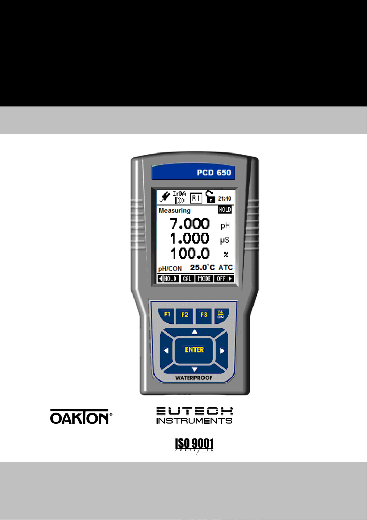
1.1.1 Display Overview
Indicators Used in Header Area
Power Source & Battery Level
Power Source: DC Adapter
Data Transmission mode: LED
Data Transmission mode: Infrared
Data Logging Mode: Internal
Memory
1.1.2 Key Functions
Key Function
Selects the function shown (in the display) just above the
key. (For ON key, press and hold for 3 seconds.
Navigates to next available functions
Conductivity range of the probe
Average slope of the pH probe
Current Time in 24 Hour format
Password Protection: Disabled
Password Protection: Enabled
Increment/decrement values in Setup & Calibration modes.
Navigates to sub groups in Setup selection screen.
In Setup mode, confirms selection or modified values
In Calibration mode, confirms calibration points or modified
values
3
Page 12
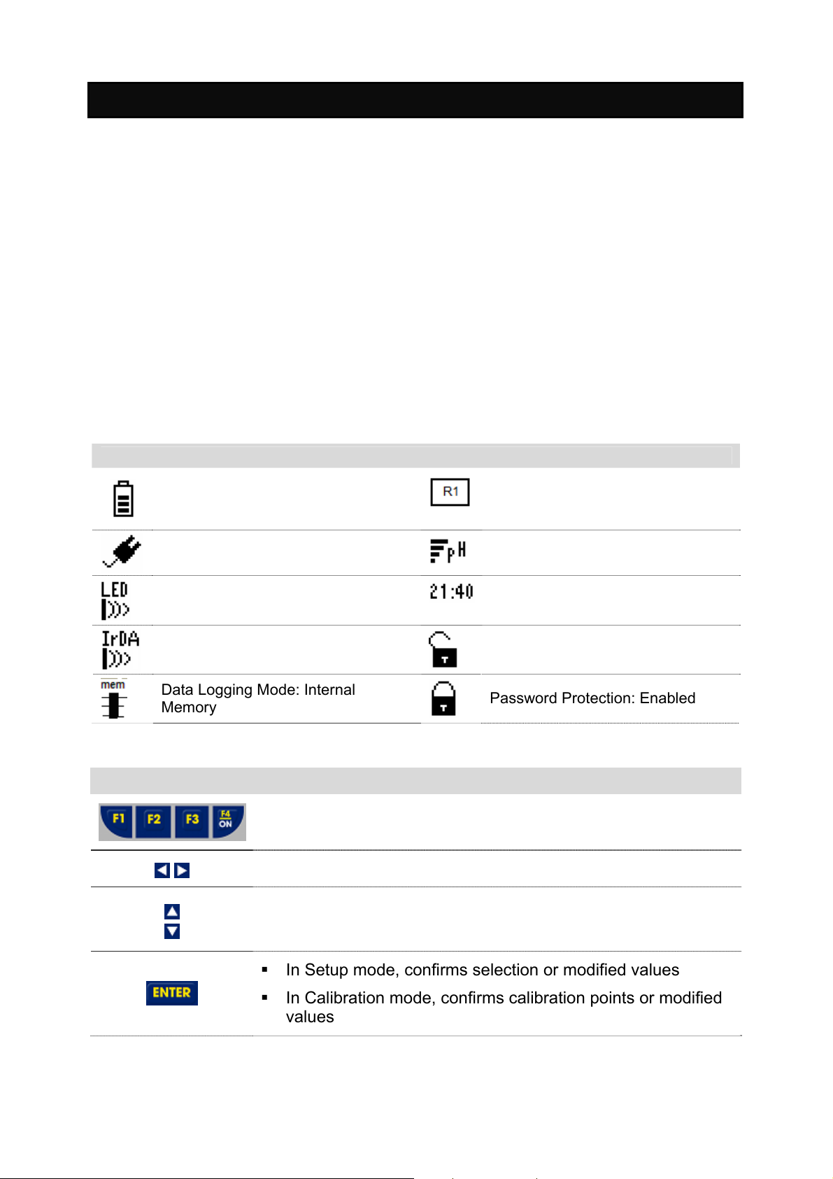
1.2 Inserting Batteries
NOTE: Please ensure that the gasket is in place otherwise the instrument will
not be waterproof.
Power up your meter using either:
1. Four ‘AA’ size 1.5 V alkaline batteries (supplied) or,
2. 9V DC power adapter (Optional in some models).
1.2.1 Inserting batteries for the first time
1. Use a Phillips screw driver to remove the four screws holding the battery
cover.
2. Insert the batteries in the right direction.
3. Replace the battery cover and screws. Note the ▲UP symbol marked on the
cover.
4. Press the ON (F4) key. Hold the key down until the display appears.
5. Set the system date & time before you start operating the meter for the first
time.
1.2.2 Changing batteries subsequently
1. Connect the adapter before changing the batteries.
2. If DC adapter is not available, switch off the meter and change the
batteries within 30 seconds to avoid resetting the clock. This prevents the
system time from resetting automatically.
4
Page 13
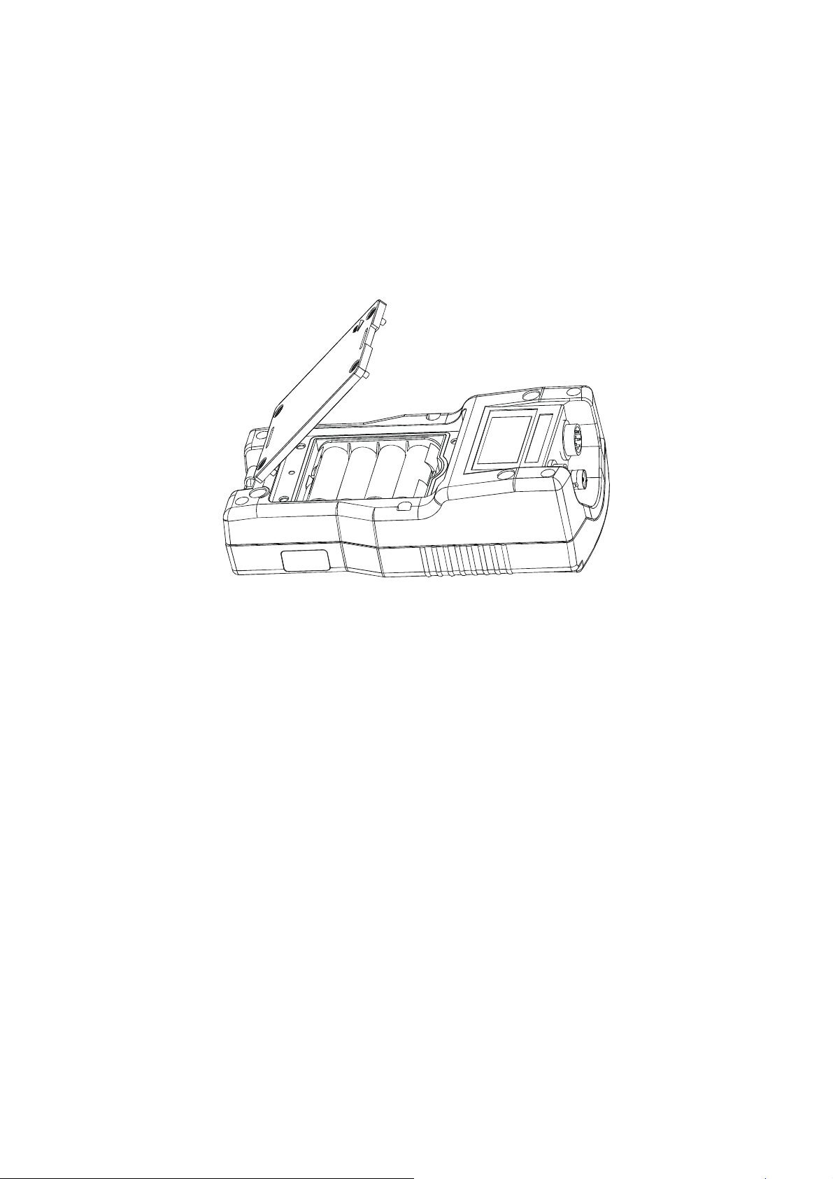
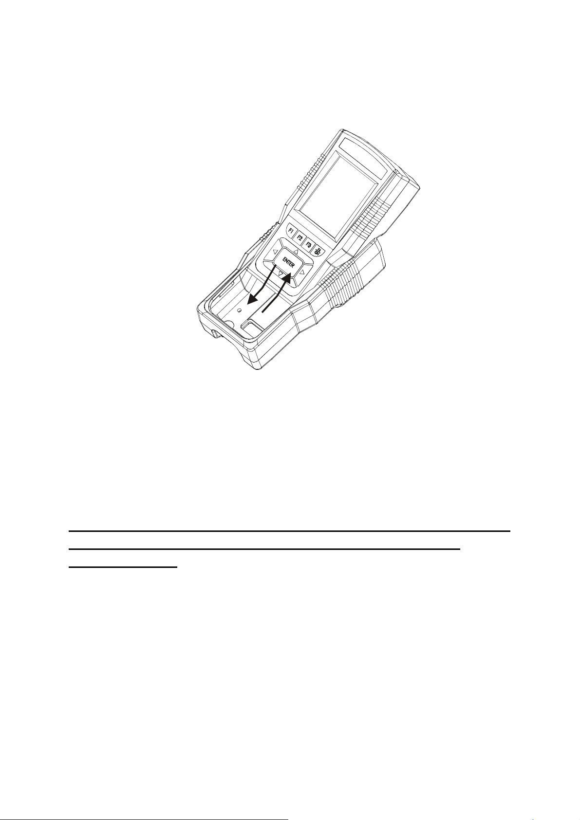
1.3 Attaching the Belt
To attach the safety belt:
1. Use a Phillips screw driver to remove the four screws holding the battery
cover.
2. Insert the safety belt through the two slots as indicated below.
3. Screw the battery cover back on. Note the ▲UP symbol marked on the
cover.
4. Insert your palm between the belt and the body of the meter and adjust the
hook & loop fastener.
Note the correct side
of the belt
Battery Cover
Hook & Loop
fastener
5
Page 14
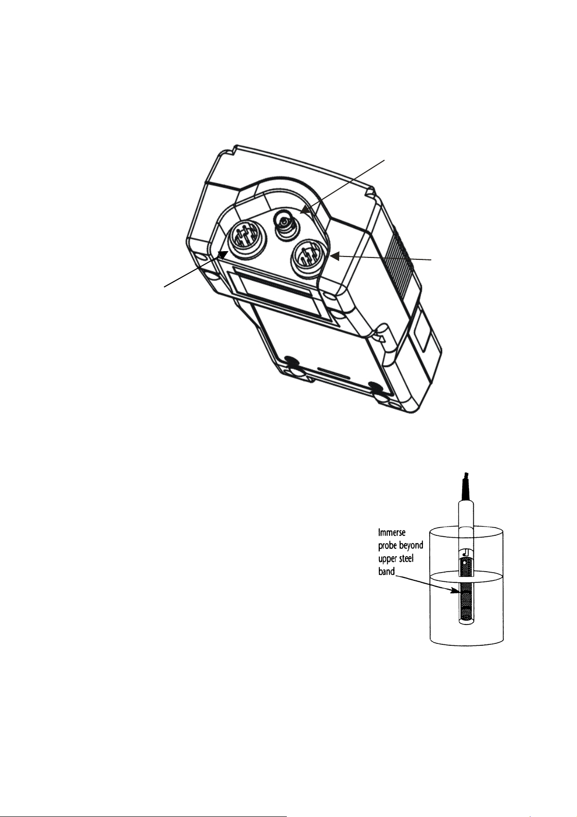
1.4 Connecting Peripherals
1.4.1 Probes (pH/Conductivity/DO)
Attach the probes with correct type of connectors as indicated.
Conductivity Probe
with built in
temperature sensor
(8-pin Connector)
Use this socket for
the standalone
temperature probe
in the pH only
models.
pH Probe (BNC)
DO Probe with built
in temperature
sensor (6-pin
Connector)
Use the electrode properly for best results:
1. Keep the protective plastic electrode guard in
tact during measurement and calibration. DO
NOT REMOVE IT.
2. Always immerse the electrode beyond upper
steel band as shown.
3. Be sure to remove the protective electrode
storage bottle or rubber cap of the pH electrode
before calibration or measurement.
NOTE: If the electrode has been stored dry, wet the electrode in clean water
for 10 minutes before calibrating or taking readings to saturate the pH electrode
surface and to minimize drift.
6
Page 15
1.4.2 Protective Rubber Boot
The rubber boot protects the meter when used in the field. For bench top
applications, lift up the stand at the back of the rubber boot.
PLEASE SET UP THE SYSTEM BEFORE YOU BEGIN USING
THE METER. USE THE FOLLOWING OVERVIEW FOR
SETUP MODE:
7
Page 16
2. System Setup Mode For All Meters
2.1 About Setup Mode
The setup mode lets you configure various parameters & settings of the meter.
You can choose to password-protect your settings, so that other users who may
use the meter will not be able to change the settings.
Setup mode consists of the following sub-groups:
System – General settings of the meter
pH / mV / Ion / Conductivity / TDS / Salinity / Resistivity / O2 mg/L
(ppm) / O2 (%) – The pH / mV / Ion / Conductivity / TDS / Salinity /
Resistivity / O
control the operating parameters of their respective mode (Please refer to
individual parameter sections for more information).
Temperature - Temperature measurement & calibration related settings.
2.2 Accessing Setup mode
1. Switch the meter on. The meter goes to measurement mode.
2. Press left or right arrow key on the keypad to navigate to other
available functions until you see SETP function in the LCD.
mg/L (ppm) / O2 (%) Setup screen presents many options to
2
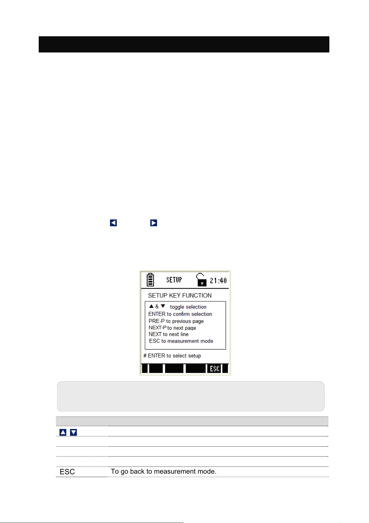
3. Press SETP (F1) and Setup Key Function screen appears. This page
describes the key functions for configuring various parameters and settings
of the meter.
Note: If the meter is password protected, you will be prompted to enter a
password before accessing Setup Key Function screen.
Function Keys available in setup key function screen:
ENTER
NEXT-P
NEXT
ESC
To select individual setup
To select or confirm the selection.
To navigate to next page.
To go to next parameter without saving the changed parameter.
To go back to measurement mode.
8
Page 17
1. Press ENTER key to select Setup Selection screen.
2. Press up or down arrow key to go to required setup sub-group.
3. Press ENTER key to select the currently shown sub-group.
Figure 1: Setup Selection Screen
Function keys available in setup selection screen:
(F1)
(F2)
(F3)
ENTER
ESC (F4)
(Not functional)
(Not functional)
(Not functional)
Goes to required setup sub-groups
Selects the current sub-group
Goes to measurement mode from where you entered setup
(Not functional)
2.3 Setup Selection: System Settings
System Settings Page 1 – General Settings
Figure 2: System Settings Page 1 – General Settings
9
Page 18
System setup sub-group allows you to configure general settings of the meter.
The settings are displayed in 6 pages. Press NEXT-P (F2) and PREV-P (F1) to
navigate through these pages.
Parameter Description Factory Default
STABLE
Indicator
Stability
Criteria
Auto Hold
ENABLE - The meter displays ‘Stable’ indicator in the
measurement screen as per the ‘STABLE CRITERIA’
defined below.
DISABLE – ‘Stable’ indicator does not appear.
SLOW – The reading is stabilized slowly and exhibits
good repeatability
MEDIUM – Reading stability is averaged between
slow & fast stability
FAST – Reading is stabilized quickly at the cost of
repeatability.
(This parameter has no effect if ‘STABLE’ parameter
is disabled)
ENABLE - The meter holds the reading in the
measurement screen, if the reading is ‘Stable’ for 5
seconds.
If this is enabled, ‘Response time’ appears in the
measurement screen, indicating the average response
time of the probe.
DISABLE – The reading is not held
(This parameter has no effect if ‘STABLE’ parameter
is disabled. The response time may not work if the
system time has not been set as described previously.
ENABLE
FAST
DISABLE
Tem. Display
from
Allows you to select temperature from pH/COND/DO
probes to display in multi measurement screen.
For PCD 650-pH/COND->DO
Display
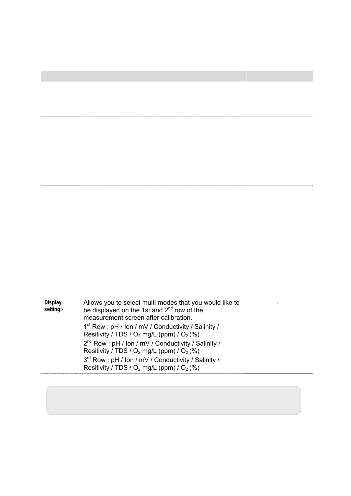
setting:-
Allows you to select multi modes that you would like to
be displayed on the 1st and 2
nd
row of the
measurement screen after calibration.
st
1
Row : pH / Ion / mV / Conductivity / Salinity /
Resitivity / TDS / O
nd
2
Row : pH / Ion / mV / Conductivity / Salinity /
Resitivity / TDS / O
rd
3
Row : pH / Ion / mV / Conductivity / Salinity /
Resitivity / TDS / O
mg/L (ppm) / O2 (%)
2
mg/L (ppm) / O2 (%)
2
mg/L (ppm) / O2 (%)
2
Note: In order to activate the RESPONSE TIME function, you have to first
activate the STABLE and AUTO HOLD functions.
-
-
10
Page 19
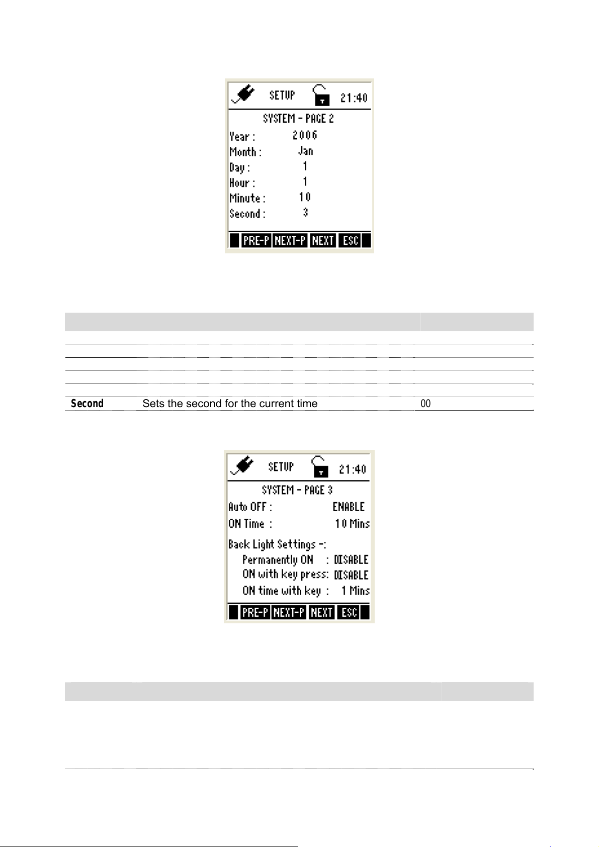
System Settings Page 2 – Date & Time
Figure 3 : System Settings Page 2 – Date & Time
This page allows you to set the date & time of the meter.
Parameter Description Factory Default
Year
Month
Date
Hour
Minute
Second
Sets the current year
Sets the current month
Sets the current date
Sets the hour (24 Hours) for the current time
Sets the minute for the current time
Sets the second for the current time
2006
Jan
01
00
00
00
System Settings Page 3 – Auto-Off & Backlight
Figure 4 : System Settings Page 3 – Auto-Off & Backlight
This page allows you to set auto-off and back light related parameters.
Parameter Description Factory Default
Auto OFF
ENABLE – Turns the meter off automatically if no key is
pressed for the time period specified in ‘ON TIME’ below.
However, this will happen only if you are using the battery,
NOT when the meter is plugged into an AC power source
or when it is printing data.
ENABLE
11
Page 20
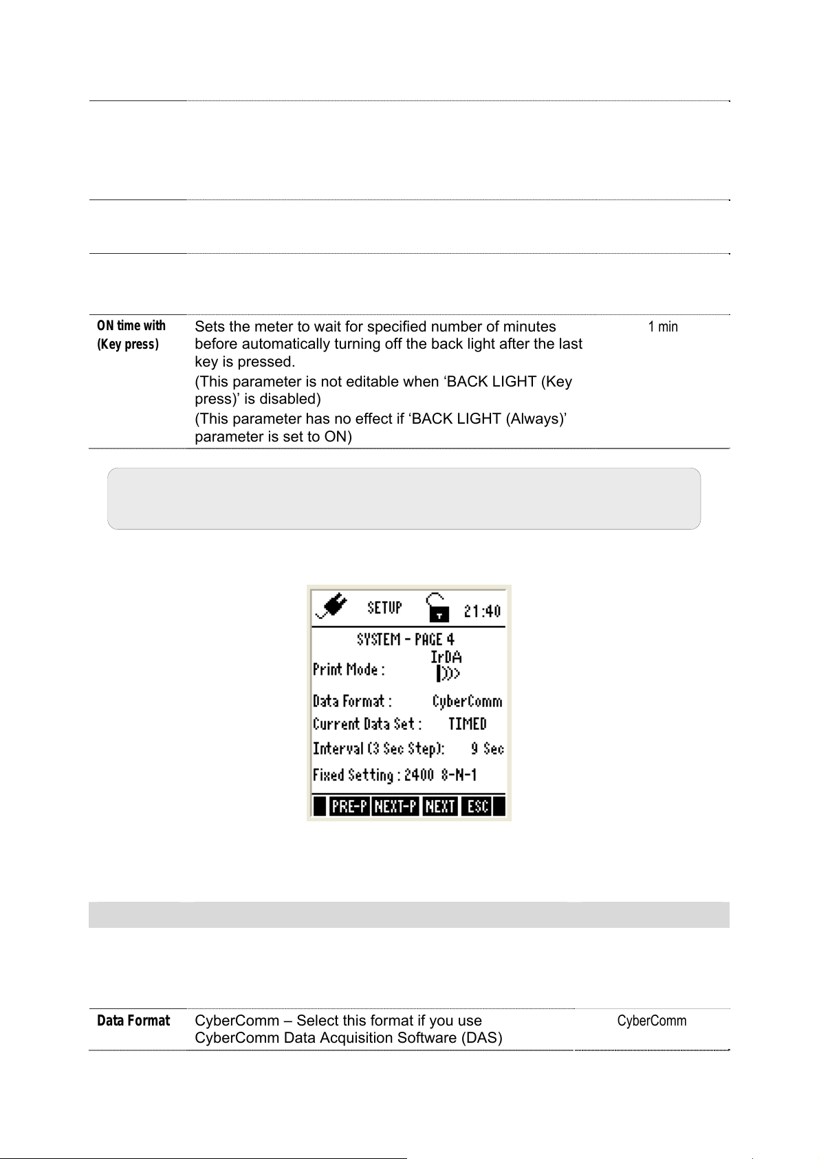
ON Time
Back Light
(permanently
ON)
Back Light
ON with (Key
press)
ON time with
(Key press)
DISABLE – Meter does not turn off automatically.
After the last key is pressed, no. of minutes the meter
should wait before automatically shuts down the meter.
Maximum range: 30 min
(This parameter has not editable if ‘AUTO OFF’ parameter
is disabled)
ENABLE – Sets the back light always on.
DISABLE – Sets the backlight always off.
ENABLE – The back light of the LCD is automatically on
when any key is pressed.
DISABLE – Does not turn on the back light automatically.
Sets the meter to wait for specified number of minutes
before automatically turning off the back light after the last
key is pressed.
(This parameter is not editable when ‘BACK LIGHT (Key
press)’ is disabled)
(This parameter has no effect if ‘BACK LIGHT (Always)’
parameter is set to ON)
10 min
DISABLE
DISABLE
1 min
Note: The above settings may not work if the system time has not been
set as described previously.
System Settings Page 4 – Wireless Serial Data Communication
Figure 5: System Settings Page 4 – Wireless Serial Data Communication
This allows you to set wireless serial data communication related parameters.
Parameter Description Factory Default
Print Mode
Data Format
IrDA – Sets serial data communication protocol to IrDA
LED – Sets serial data communication protocol to
RS232C
MEM- Logs data to meter’s memory.
CyberComm – Select this format if you use
CyberComm Data Acquisition Software (DAS)
IrDA
CyberComm
12
Page 21
TEXT – Select this format if you use any other method
(such as Windows
This parameter is used when downloading data from
the meter through IrDA
®
Hyperterminal)
Current Data
Set
Interval
(3 Sec Step)
Fixed Setting
TIMED – Prints measurement data continuously at the
interval specified in ‘INTERVAL’ parameter below.
SINGLE – Prints only the currently measured reading
This parameter applies when PRIN key is pressed from
measurement mode to send the currently measured
readings to the computer.
Time interval at which the meter should send currently
measured data to the printer/CyberComm/PCD
Acceptable range : 3 sec to 600 sec (in 3 sec steps)
(This parameter is applicable when ‘CURRENT DATA
SET’ is set to ‘TIMED’ and this is not editable when
‘CURRENT DATA SET’ is set to ‘SINGLE’)
Indicates serial communication settings in the format of
‘Baud rate, Data bits-Parity bits-Stop bits’. This
parameter is not editable.
TIMED
9 Sec
2400 8-N-1
System Settings Page 5 – Password Protection
This allows you to enable password protection for the setup mode & calibration
mode:
Figure 6: System Settings Page 5 – Password Protection
When you enable password protection, the meter prompts you to enter the password
whenever you try to access the Setup or Calibration mode. The meter does not allow
you to edit setup parameters or perform a new calibration unless you enter the
correct password. If an incorrect password is entered for 3 consecutive times, the
meter goes to measurement mode.
Parameter Description Factory Default
Password ENABLE – Sets password protection for the setup &
DISABLE
13
Page 22
Protection
calibration mode. If this is enable you need to specify
a 5-digit password in the ‘SET PASSWORD’
parameter below
DISABLE – Disable password protection of the meter
Set Pass
Word
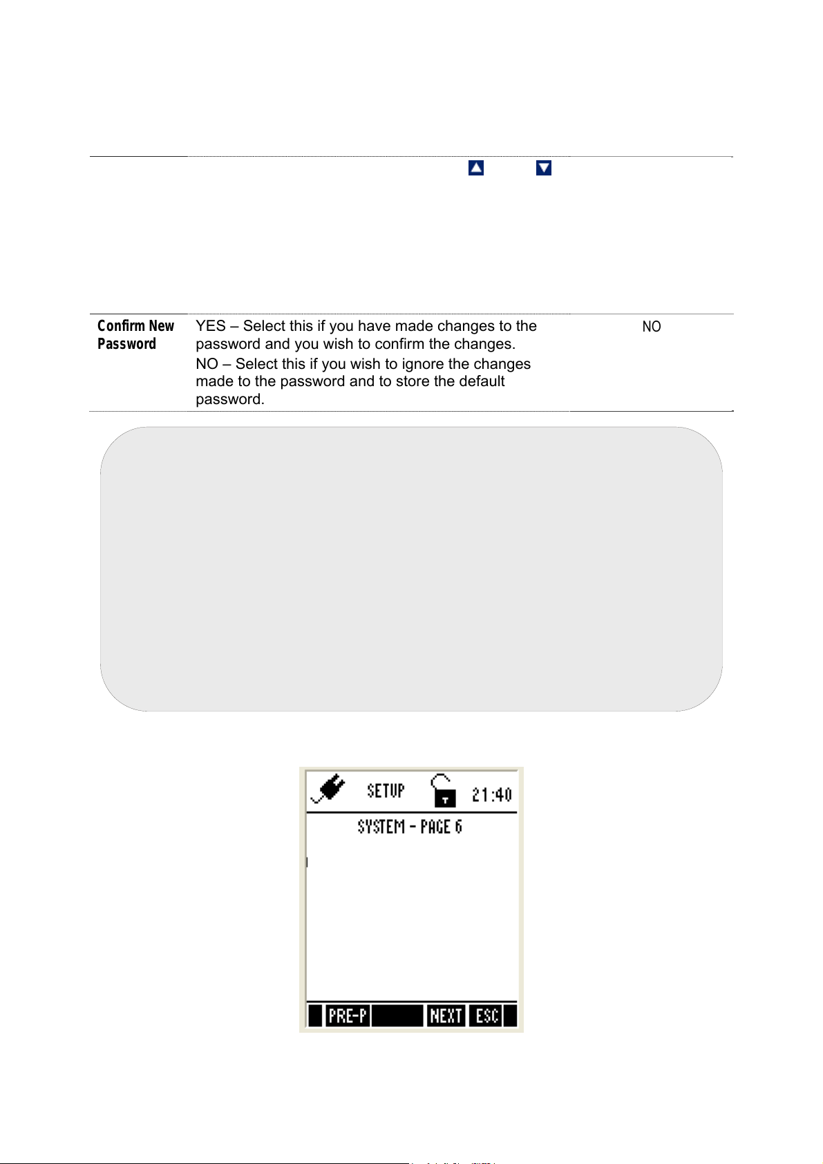
Confirm New
Password
Specify your 5-digit password here. Use
(Up) &
(Down) key to select a number and then press ENTER
key to confirm and move to the next digit.
Do not set your password to ‘00000’ as this is
reserved for ‘read-only’ password.
(This parameter is not editable when ‘PASSWORD
PROTECT’ is disabled)
YES – Select this if you have made changes to the
password and you wish to confirm the changes.
NO – Select this if you wish to ignore the changes
made to the password and to store the default
password.
mportant:
1. Please memorize the password that you have entered after enabling the
password protection. Without it, you can’t disable the password
protection or reset the meter to factory defaults. However, if the user
forgets his password, he can contact the nearest distributor or
Eutech Instruments/Oakton Instruments to request for meter
password. This would be unique to each instrument and would be tied
to the serial number of the unit.
2. Default password ‘88888’ is valid only if it is not changed with new
password.
3. You can enter ‘00000’ (read-only password) if you wish to view the setup
parameters. You are not allowed to modify any parameter when you
enter ‘read-only password’.
88888
NO
System Settings Page 6 – Data Memory & Factory Settings
Clear logged Data Memory: NO
Display Contrast: 12
Factory Reset: NO
Figure 7: System Settings Page 6 – Data Memory, Display Contrast & Factory Settings
14
Page 23
This allows you to clear the memory, display contrast and reset the meter to factory
defaults.
Parameter Description Factory Default
Clear logged
Data Memory
Display
Contrast
Factory Reset
YES – Select this to clear all the stored data from the
meter’s memory
NO – Select this if you do not wish to clear the stored
data from the meter’s memory
Adjust display contrast from 1 - 25
YES – Select this if you wish to reset the meter to its
factory default settings. This includes:
Deleting your calibration data
Resetting setup parameters to factory defaults
(except date & time)
Deleting your stored data in the memory
NO – Select this if you do not wish to reset the meter.
When ‘YES’ is selected and confirmed by pressing
ENETR key, the meter is reset to factory defaults and
then the meter goes to measurement mode.
NO
12
NO
2.4 Accessing Setup mode when password protection enabled
1. Switch the meter on. The meter goes to measurement mode.
2. Press right arrow key to navigate to other functions on the right-side of
LCD.
3. Press SETP (F1) to go to Setup mode. Login password screen appears. The
meter expects the 5-digit password specified in system setup.
Figure 8: Login Password
15
Page 24

Note: You can enter ‘00000’ (read-only password) if you wish to view the
setup parameters. You are not allowed to modify any parameter when
you enter ‘read-only password’.
1. Press up & down arrow keys to enter the first digit of the password and
then press NEXT (F3) key to move to the next digit.
2. The next digit is selected. Press up & down arrow keys to enter the
second digit of the password. Enter all 5-digits.
3. Press ENTER key to confirm the password.
Note: If you enter an incorrect password, the screen shows “Try Again”. If
an incorrect password is entered three consecutive times, the meter goes
into measurement mode. If you forget the password, there is no way to
access the system setting and calibration. Please contact your authorised
dealer for assistance.
1. When the correct password is entered, the Setup Key Function Screen
appears.
2. Press Enter key to launch Setup Selection Screen. Press up or down
arrow key to go to required setup sub-group.
3. Press ENTER key to select the sub-group.
2.5 Modifying Setup parameters
1. Press NEXT (F3) key to select individual setup parameters sequentially.
2. Press (Up) or (Down) arrow key to change the value of a selected
parameter.
3. Once you have changed a value:
• Press ENTER key to save the change, or
• Press NEXT (F3) key to go to the next parameter without saving the
changed parameter.
4. Press NEXT-P (F2) or PRE-P (F1) to navigate to next or previous page.
5. Press ESC (F4) to exit from setup mode.
(Refer to Page 9 for current function keys settings)
16
Page 25

3. Calibration Mode For All Meters
3.1 About Calibration
The 600 series meters are factory calibrated and allows you to measure
pH/mV/ion/conductivity/resistivity/TDS/salinity/DO(%)/DO(mg/L) respective to
the model(s) you have purchased. Calibrate to all measurement ranges to
ensure the highest accuracy in any given measurement range. This should be
done before you make measurements for the first time and also each time a
new electrode is attached to the meter or when you suspect that the
meter/electrode is out of calibration.
3.2 About Conductivity/ Resistivity/ TDS/ Salinity Calibration
Before measuring conductivity, resistivity, TDS or salinity, you will need to
calibrate the meter with known conductivity, resistivity, TDS or salinity values.
The meter is capable of performing either automatic or manual calibration.
In the automatic calibration mode, the meter automatically detects and verifies
the appropriate known calibration standards solutions being calibrated before
accepting these particular calibration standards as one of its calibration values
in a specific measurement range. This automatic calibration mode frees you
from cumbersome calibration procedure.
The meter can perform a single- or multi-point calibration. You will need to set
your meter to single- or multi-point calibration in the Setup mode for
conductivity, resistivity, TDS or salinity.
Refer to the setup section for the particular mode you will be measuring. Instead
of calibrating for TDS directly using TDS calibration standard solutions, you can
have TDS calibration by using the conductivity calibration method and enter the
appropriate TDS conversion factor into the meter.
For more information regarding TDS Conversion Factor determination, please
go to the ‘Appendix’ of this manual.
3.3 Preparing the Meter for Calibration
Before starting calibration, make sure the meter is in the appropriate
measurement mode.
For pH
Connect the pH probe to the BNC connector of the meter.
Be sure to remove the protective electrode storage bottle or rubber cap of the
electrode before calibration or measurement. If the electrode has been stored
dry, wet the electrode in clean water for 10 minutes before calibrating or taking
readings to saturate the pH electrode surface and minimize drift.
Wash your electrode in clean water after use, and store in electrode storage
solution. If storage solution is not available, use pH 4.01 or 7.00 buffer solution.
Do not reuse buffer solutions after calibration. Contaminants in the solution can
affect the calibration, and eventually the accuracy of the measurements.
17
Page 26

It is recommended that you perform at least a 2-Point Calibration using
standard buffers that adequately cover the expected measurement range, prior
to measurement.
For Ion
Connect the ISE to the BNC connector of the meter.
Remove plastic protective cap of ISE. Briefly rinse the electrode with clean
water to remove any residues. Rinse ISE before and after each calibration or
sample measurement to avoid cross-contamination. Ensure that you use new or
fresh standard solutions during calibration. Do not reuse Ion standard solution
as it may be contaminated and affect the calibration and accuracy of
measurements.
For Conductivity
Connect the conductivity probe with built-in temperature sensor into the 8-pin
connector of the meter.
For best results, select a standard value close to the sample value you are
measuring. Alternatively use a calibration solution value that is approximately
2/3 the full-scale value of the measurement range you plan to use. For example,
in the 0 to 2000 µS conductivity range, use a 1413 µS solution for calibration.
Perform calibration for all measurement ranges to ensure the highest accuracy
throughout all measurement range.
If you are measuring in solutions with Conductivity lower than 100 µS/cm or
TDS lower than 50 ppm, calibrate the meter at least once a week to ensure
accuracy. If you are measuring in the mid ranges and you wash the electrode in
de-ionized water and store it dry, calibrate the meter once a month. If you take
measurements at extreme temperatures, calibrate at least once a week.
Ensure that you use new conductivity standard solutions or sachets during
calibration. Do not reuse standard solutions as it may be contaminated and
affect the calibration and accuracy of measurements. Use fresh calibration
solution each time you calibrate your meter. Keep solutions in a dry and cool
environment if possible.
For DO(%) and DO (mg/L) Calibration
Before starting calibration, make sure you are in the correct measurement mode
and in the correct calibration sequence. The temperature and the %
Saturation calibration must be done first before attempting to do the mg/L
(ppm) Concentration calibration.
Rinse the probe well in the de-ionized (DI) water or rinse solution and wipe the
probe carefully taking care of the membrane.
Calibrate the meter in all the modes to ensure the highest accuracy throughout
the DO measurement range. In % Saturation, the meter is able to perform either
a one point calibration or a 2 point calibration. For one point calibration, it is
recommended that you perform a 100% Saturation calibration in saturated air. If
you opt for 2 point calibration, you can calibrate for 100% Saturation in
saturated air and 0% Saturation using a zero oxygen solution.
18
Page 27
All new calibration values will automatically override the existing data. It is
recommended to calibrate the meter periodically and or if it is suspected to be
inaccurate.
Always rinse the probe with either DI water or rinse solution before and after
each calibration/sample measurement. When calibrating in air, make sure that
any water droplets from the probe’s membrane are removed.
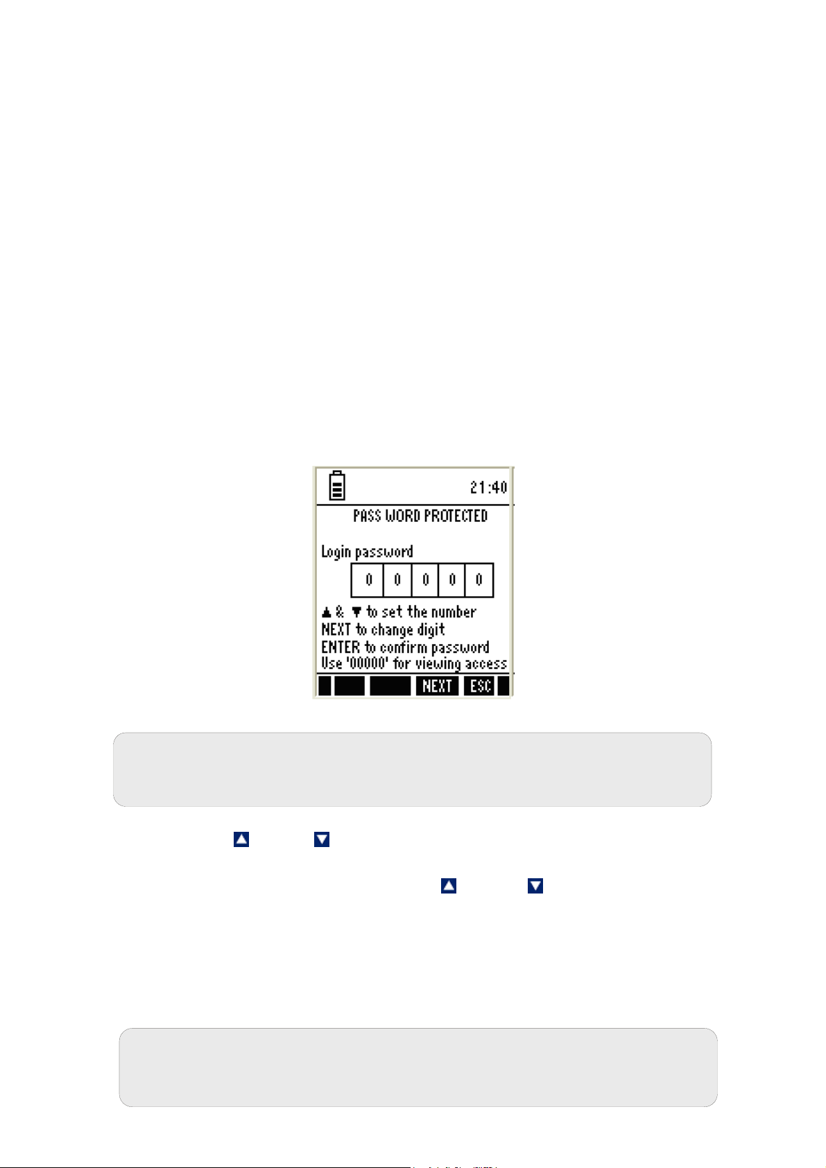
3.4 Accessing Calibration mode
From measurement mode, press CAL (F2) key. The meter goes to
corresponding calibration mode, based on the selected measurement mode. If
the meter is password protected, you will be prompted to enter password.
3.4.1 Accessing Calibration mode when password protection enabled
1. Make sure you are in measurement mode. If required, press MODE (F3) to
switch to the measurement mode for which you wish to perform calibration.
2. Press CAL (F2) to go to calibration mode. Login Password screen appears
(Figure 9). The meter expects the 5-digit
setup.
password specified in system
Figure 9 : Login Password
Note: You can enter ‘00000’ (read-only password) if you wish to view the
calibration report of the last calibration. You are not allowed to perform
calibration when you enter ‘read-only password’.
1. Press up
then press NEXT (F3) key to move to the next digit.
2. The next digit is selected. Press up & down arrow keys to enter the
second digit of the password.
3. Similarly enter all 5-digits.
4. Press ENTER key to confirm the password.
5. When the correct password is entered, the ‘Calibration – Rinse Electrode’
screen will appear.
Note: If you enter an incorrect password, the screen shows ‘Try again’. If
an incorrect password is entered for 3 consecutive times, the meter goes
to measurement mode.
19
& down arrow keys to enter the first digit of the password and
Page 28

20
Page 29
4. Measurement Mode For All Meters
t
d
d
4.1 About Measurement Mode
The following is the full range of measurement modes in the WP 600 series
meters:
Temperature measurement mode
pH measurement mode
mV measurement mode
Ion measurement mode
Conductivity measurement mode
TDS measurement mode
Salinity measurement mode
Resistivity measurement mode
O2 % - DO percentage saturation measurement mode
O2 mg/L (ppm) - DO concentration mode
Only the PCD 650 model is equipped with all of them.
The meter automatically goes to the mode that was used before it was turned
off the last time. Press MODE (F3) key to select your required measurement
mode.
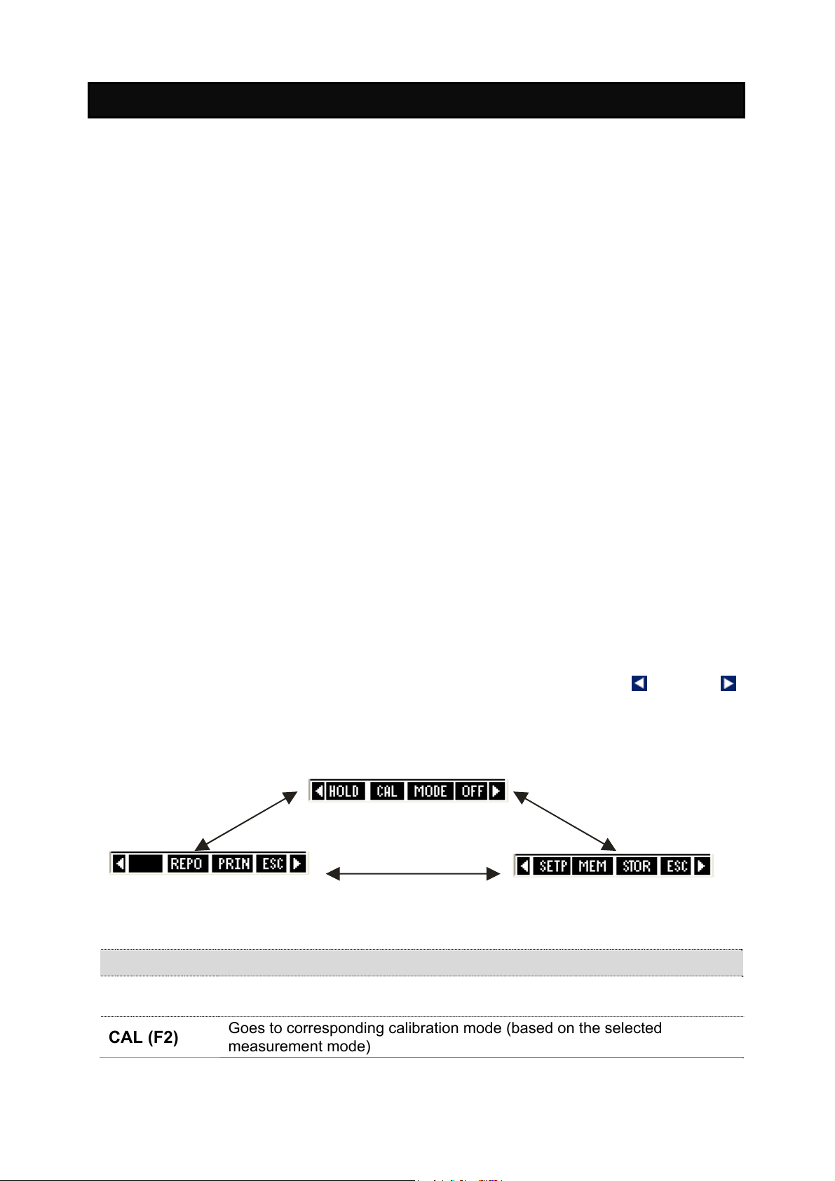
4.1.1 Accessing functions
There are many functions available in the measurement mode. Use the 4
Function keys (F1, F2, F3 & F4) to access them. The first group of functions
appear when you enter the measurement mode. Press the left
arrow key to navigate to the 2
nd
and 3rd function groups.
or right
s
1
function group
r
3
function group
n
2
function group
Function Keys available in measurement screen (1st Group):
HOLD (F1)
CAL (F2)
Holds the current reading in the display. The ‘HOLD’ indicator starts
blinking. Press HOLD key again to release the reading
Goes to corresponding calibration mode (based on the selected
measurement mode)
21
Page 30
MODE (F3)
OFF (F4)
ENTER
Function Keys available in measurement screen (2nd Group):
SETP (F1)
MEM (F2)
STOR (F3)
ESC (F4)
Function Keys available in measurement screen (3rd Group):
REPO(F2)
PRIN (F3)
ESC (F4)
ENTER
Switches between measurement modes
Power off the meter (press and hold this key for 3 seconds)
Switches between functions groups available in measurement mode
(Not functional)
(Not functional)
Goes to setup mode
Shows stored data in the memory
Stores the currently displayed reading in the memory
Shows 1st Group of functions
Shows corresponding calibration report (based on selected measurement
mode)
Sends the currently displayed reading to the computer through IrDA. (This
key has to be pressed to establish communication with CyberComm PCD
application through IrDA). If data logging mode has been selected in
System Setup then it sends data automatically to meter’s memory.
Shows 1st Group of functions
Switches between functions groups available in measurement mode
(Not functional)
(Not functional)
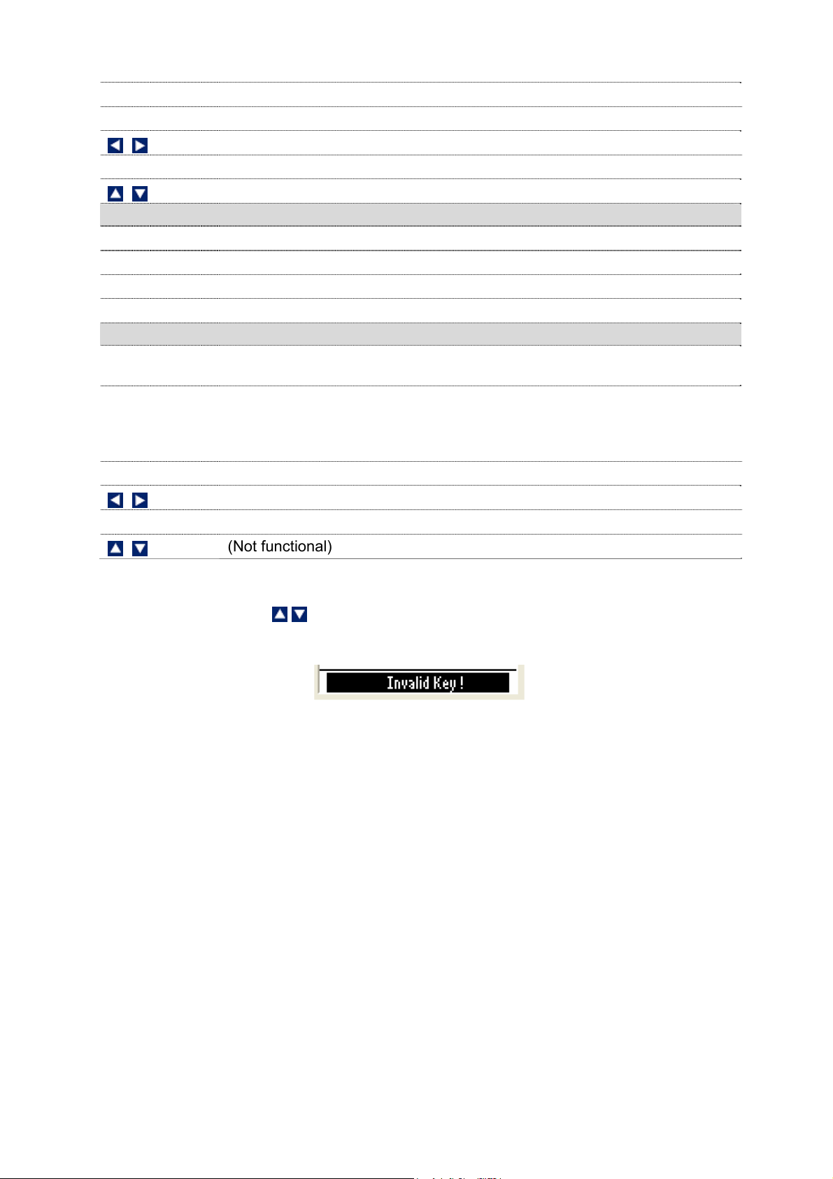
Note: If you press a function key that is not relevant to measurement mode (for
example ENTER, , ) the meter shows ‘Invalid key!’ message in the footer
area of the screen as shown here.
Figure 10 : Invalid Key Prompt
4.2 Taking Measurements
4.2.1 Prepare the meter for measurement
Perform a calibration test if you change to a new probe and connect the probe
to the meter before measuring.
4.2.2 Taking a reading
1. Press ON (F4) key to switch the meter on. Hold for 3 seconds.
2. Press MODE (F3) to select your required mode.
3. Dip the appropriate probe into the sample solution.
4. The LCD shows a ‘Stable’ indicator if this feature was enabled during the
setup. Note the reading.
22
Page 31

4.2.3 Stable reading indicator
You can configure the meter so that LCD displays a ‘Stable’ indicator when the
reading does not vary for 2 consecutive seconds. The amount of variations
allowed can be set at ‘Slow’, ‘Medium’ or ‘Fast’.
4.2.4 Holding a reading
In some situations, you may want to freeze (hold) the measured reading in the
LCD for a delayed observation. You can hold a reading in two different ways:
Manual Hold – Allows you to hold the reading by pressing HOLD (F1) key at
any time you want. When you hold a reading, the ‘HOLD’ indicator starts
flashing. The readings (including temperature reading) will be held until you
press any other key again.
Auto-Hold –The meter automatically holds the reading if it is ‘Stable’ for 5
consecutive seconds. This feature needs to be enabled in the setup. Press
HOLD (F1) key to release the reading.
4.3 Automatic Temperature Compensation (ATC)
Connect an appropriate probe to the meter and select ‘ATC mode’ in the
temperature setup for the pH/ conductivity/ DO reading to be automatically
compensated for temperature variations.
If you select ‘ATC’ without connecting a probe to the meter, the LCD will show
the word ‘UNDER’ for temperature reading.
Figure 11: Under Range
Note: The factory default value for normalization temperature is 25°C.
4.3.1 Manual Temperature Compensation (MTC)
If an ATC probe is not available,
the temperature. This is suitable when the temperature of your sample is
sufficiently stable. Select ‘MTC mode’ in the temperature setup. Press CAL
(F2) and then press NEXT key. Press TEMP (F1) to go to temperature
calibration. Enter the temperature value of your sample.
you can choose to manually compensate for
23
Page 32

4.4 Alarm set point (For pH/conductivity/DO)
You can set the meter to display an alarm when the pH/ conductivity/ salinity/
resistivity/ TDS/ DO (%)/ DO (mg/L) reading goes higher or lower than
predefined set points. Refer to ‘Setup’ pages of respective modes to set alarm
points for pH, conductivity and DO.
Figure 12 : Hi Alarm
4.5 Calibration Due (CAL-DUE) Indicator (For pH/conductivity
You can set a reminder to be displayed in the LCD when the next calibration is
due. Set the number of days in the pH/conductivity/DO Setup and the meter will
remind you when the days elapse from your last calibration date.
5. TRANSFERRING AND PRINTING DATA
Please refer to this section after completing calibrations and
taking measurements.
5.1 CyberComm 600 Data Acquisition Software
Your meter is shipped with a companion software application called
CyberComm 600 Data Acquisition Software (DAS).
For details on installation, connection and usage of the software, please read
the manual that comes with the software CD.
/DO)
5.2 Working with Memory functions – Auto Data Logging
The 600 series meters have a memory capacity to store up to 500 sets of data
measurements. You can view the stored data using the MEM (F2) function key.
You can also transfer this data wirelessly via infrared to a Computer or print it
directly to a microprinter.
24
Page 33

5.2.1 Logging data automatically in the meter’s memory
1. Make sure that the Print mode is set to ‘data logging mode’ in the System
Setup. You can also specify the time interval for each transfer.
2. From measurement mode, press PRIN (F3) to start saving data
automatically in meter’s memory. The memory location of the transferred
reading is shown in the bottom-left of the screen.
NOTE: This symbol will
appear if data logging mode
has been selected in “System
set up’. It will automatically
start saving data in meter’s
memory, when PRIN (F3) key
is pressed.
Memory Location
where readings are
being saved
.
5.2.2 Storing a current measurement (In IrDA and LED print mode: Applicable to all
modes)
1. Make sure you are in the measurement mode.
2. Press left or right arrow key to navigate to other available functions
until you see STOR function in the LCD.
3. Press STOR (F3) key to store the current reading. The bottom left of the
screen will show the memory location where this reading is being saved.
5.2.3 Viewing stored data
Make sure you are in measurement mode.
1.
2. Press left or right arrow key to navigate to
other available functions until you see MEM
function in the LCD.
3. Press MEM (F2) key to view the stored data.
The last data entry stored is shown in the
display with its memory location at the top-right
corner of the screen [Immediately under the
time]. (See following diagram)
4. To navigate to a particular memory location,
press the up
or down arrow key to select it
and then press the ENTER key. The meter will
show the stored data in the memory location you selected.
5. Press NEXT (F3) key to return to the measurement mode.
6. Press ESC (F4) key to return to the main screen of the measurement mode.
25
Page 34

5.2.4 Transferring stored data to the Computer (CyberComm) through IrDA
1. Make sure the CyberComm 600 application is up and running (Refer to the
manual in the software packaging to install).
2. Make sure your meter’s IrDA port is facing the IrDA port of the computer.
3. Go to the ‘stored data viewing’ screen as shown above diagram (Use MEM
[F2] key.
4. Press PRIN (F2). The screen appears for you to select printing options.
5. Press up or down arrow key to select either ‘all (memory) locations’ or
the ‘current memory location’, and then press ENTER key.
6. If you have selected ALL LOCATIONS, then you can specify the time
interval in between each transfer. Press up or down arrow key to
select from 1 to 50 second intervals then press ENTER key.
7. At the CyberComm screen on your computer, press Find Device button.
8. Once CyberComm finds the meter, click the Connect button to establish a
connection.
9. Data will be sent from your meter to the computer through IrDA and the
connection will stop automatically when the transfer is complete.
10. You can save the transferred data in your choice format : .txt, .xls etc.
26
Page 35

Transfer Stored data to CyberComm
5.2.5 Transferring stored data to a PC not equipped with infrared receiver.
If your PC doesn’t come with a built-in infrared receiver, you can use an RS
232C Adapter (sold separately) that connects directly to your PC using a
specially-designed 9-pin plug. Then use the Cybercomm or HyperTerminal
software to print your data.
You can also use the RS232C Adaptor to print your data directly to our dot
matrix microprinter (sold separately) using a custom-built 25-pin plug.
Please contact your dealer to find out more.
27
Page 36

5.2.6 Transferring stored data to a PC using an USB/ irDA Dongle.
You can purchase an USB/ irDA dongle
01X447601 (see accessories page at the back
of this manual) and transfer data from your
meter using the USB port.
Please note: This accessory is specially
engineered to match your meter’s software to
the application in your laptop or PC. If you
purchase this item from a different source, it
will NOT be compatible for transferring the
data.
28
Page 37

6. Technical Specifications
Temperature (pH and Conductivity)
Range -10.0 ºC to 110.0 ºC (14.0 ºF to 230.0 ºF)
Resolution 0.1 ºC/ 0.1 ºF
Relative Accuracy ± 0.5 ºC / ± 0.9 ºF
Temp. Input Connector 8-pin Round
Temperature (DO)
Range -10.0 ºC to 60.0 ºC (14.0 ºF to 140.0 ºF)
Resolution 0.1 ºC/ 0.1 ºF
Relative Accuracy ± 0.5 ºC / ± 0.9 ºF
Model
pH pH 600 pH 610 pH 620, PD 650,PCD 650
Range -2.00 to 20.0 pH -2.000 to 20.000 pH
Resolution 0.1/ 0.01 pH 0.1/0.01/0.001 pH
Relative Accuracy ± 0.01 pH + 1 LSD ± 0.002 pH + 1 LSD
No. of Calibration points 1 (offset) to 6 points
No. of Buffer Options 15
Calibration due alarm User configurable (up to 30 days)
Set point alarm User configurable
Auto buffer recognition Yes
USA : 1.68, 4.01, 7.00, 10.01, 12.45
pH buffer Groups & Calibration
Points
USA
Calibration
Window
Custom buffer calibration Yes (2 to 5)
Slope/Offset display Yes (Display + Icon)
mV
Range ± 2000.0mV
Resolution 0.1 mV
Relative Accuracy ± 0.2 mV + 1 LSD
Ion
Range 0.001 to 19900
Units ppm, molar, mg/L
Resolution
Relative Accuracy 0.5% FS (monovalent) 1% FS (divalent)
NIST ± 1.35 pH (for 6.86pH), ±1 pH (for all other buffers)
DIN
PWB ± 0.8 pH
NIST: 1.68, 4.01, 6.86, 9.18, 12.45
DIN : 1.09, 3.06, 4.65, 6.79, 9.23, 12.74
PWB : 4.10, 6.97
± 1.5 pH (for 7.00pH), ±1 pH (for all other buffers)
± 0.8 pH (for 1.09, 3.06, 4.65pH), ±1 pH (for 9.23, 12.74pH),
±1.34 pH (for 6.79pH)
2 or 3 digits
29
Page 38

Conductivity
Range Measuring ranges Resolution
1
2
3
4
5
0.050uS to 2.000uS
2.000uS to 9.990 uS
10.00uS to 99.99uS
100.0uS to 300.0uS
300.0uS to 999.9uS
1.000mS to 4.000mS
4.000mS to 9.999mS
10.00mS to 40.00mS
40.00mS to 99.99mS
100.0mS to 500.0mS
0.01uS*
0.01uS*
0.01uS
0.1uS
0.1uS
0.001mS
0.001mS
0.01mS
0.01mS
0.1mS
Sub range
Accuracy
1% of FS
1% of FS
1% of FS
1% of FS
1% of FS
1% of FS
1% of FS
1% of FS
1% of FS
1% of FS
Cal Standards
No
84.00uS
1.413mS
12.88mS
111.8mS
* Display resolution is 0.001 but actual
resolution shows 0.01.
TDS
Range Measuring ranges Resolution Sub range Accuracy
1
2
3
4
5
0.050ppm to 2.000ppm
2.000ppm to 9.990 ppm
10.00ppm to 99.99ppm
100.0ppm to 300.0ppm
300.0ppm to 999.9ppm
1.000ppt to 4.000ppt
4.000ppt to 9.999ppt
10.00ppt to 40.00ppt
40.00ppt to 99.99ppt
100.0ppt to 500.0ppt
0.01ppm*
0.01ppm*
0.01ppm
0.1ppm
0.1ppm
0.001ppt
0.001ppt
0.01ppt
0.01ppt
0.1ppt
* Display resolution is 0.001 but actual
resolution shows 0.01.
1% of FS
1% of FS
1% of FS
1% of FS
1% of FS
1% of FS
1% of FS
1% of FS
1% of FS
1% of FS
Salinity
Range Measuring ranges Resolution Sub range Accuracy
1
2
3
4
5
0.020ppm to 0.770ppm
0.770ppm to 9.990 ppm
10.00ppm to 99.99ppm
100.0ppm to 143.3ppm
143.3ppm to 999.9ppm
1.000ppm to 2.138ppt
2.138ppt to 9.999ppt
10.00ppt to 23.64ppt
23.64ppt to 80.00ppt
0.01ppm*
0.01ppm*
0.01ppm
0.1ppm
0.1ppm
0.001ppt
0.001ppt
0.01ppt
0.01ppt
* Display resolution is 0.001 but actual
resolution shows 0.01.
1% of FS
1% of FS
1% of FS
1% of FS
1% of FS
1% of FS
1% of FS
1% of FS
1% of FS
30
Page 39

Resistivity
Range Measuring ranges Resolution Sub range Accuracy
5
4
3
2
1
10.00MΩ to 20.00MΩ
1.000MΩ to 9.999MΩ
500.0KΩ to 999.9KΩ
100.0KΩ to 500.0KΩ
10.00KΩ to 99.99KΩ
3.333KΩ to 9.999KΩ
1.000KΩ to 3.333KΩ
250.0Ω to 999.9Ω
100.0Ω to 250.0Ω
25.00Ω to 99.99Ω
10.00Ω to 25.00Ω
2.000Ω to 9.990Ω
0.01MΩ
0.001MΩ
0.1KΩ
0.1Ω
0.01Ω
0.001Ω
0.001Ω
0.1Ω
0.1Ω
0.01Ω
0.01Ω
0.01Ω*
1% of FS
1% of FS
1% of FS
1% of FS
1% of FS
1% of FS
1% of FS
1% of FS
1% of FS
1% of FS
1% of FS
1% of FS
* Display resolution is 0.001 but actual
resolution shows 0.01.
Conductivity / TDS / Salinity /
Resistivity
COND 600 COND 610
Conductivity Range 0 to 200mS 0 to 500 mS
Salinity
Resistivity
- 80 ppt
- 0 to 20.00MΩ
TDS 200 ppt (depending on TDS factor) 500 ppt (depending on TDS factor)
Conductivity Cell constant
0.010 to 10.000
Conductivity Cell 2 & 4 Cell
TDS Conversion Factor 0.400 to 1.000
Temperature Comp. Linear Linear & Pure
Cal-Auto/Manual Yes
Cal-Single/Multi Yes
Cal Due Alarm Yes (max-30 days)
Set Point Alarm Yes
Input Conductivity 8 Pin Round
Dissolved Oxygen DO 600, PD 650, CD 650, PCD 650
DO Range 0 to 600 %/ 90 mg/l
Resolution 0.1%, 0.01 mg/L
Accuracy ± 2%, ± 0.2 mg/L
Dissolved Oxygen Probe Galvanic
Mode % Sat, mg/L, ppm
Temperature Comp. Linear
Barometric Pressure Compensation Automatic
Barometric Pressure Range 450 to 825 mmHg
Barometric Pressure Resolution 1 mmHg
Barometric Pressure Accuracy ± 1%
Salinity Correction 0 to 50 ppt
Cal Due Alarm Yes (max -30 days)
31
Page 40

Set Point Alarm Yes
Input DO 6 Pin Round
Display
Display type Dot matrix LCD with backlighting
Screen resolution 110 x 128
Viewing area 68 x 74 mm
Backlit Yes
Other
Data logging 500 data sets
Data communication IrDA / RS232C-Infrared
Auto Data logging Yes
GLP (Good Lab Practice) Yes
Ingress protection IP 67
Dimensions
Weight 380g (Without Rubber Boot)
Power Input pH 600 / 610 / 620 All other models
Battery 4 x Alkaline AA size, 1.5 V
Battery Life
Power adapter
500 Hrs (without backlight & serial data
95mm (W) x 185mm (L) x 58.5mm (H) - Without Rubber Boot
101mm (W) x 191mm (L) x 61mm (H) - With Rubber Boot
200 Hrs (without backlight & serial data
transfer)
Input: 100-240V AC
Output: DC 9-12V, 6W Max
transfer)
32
Page 41

7. Accessories
Eutech Instruments
Product Description Eutech Instruments Order Code
8 pin connector Temperature probe (3m Cable) ECPHWPTEM03J
8 pin connector Temperature probe (1m Cable) ECPHWPTEM01J
General Purpose Plastic-Body, Double Junction, Ag/AgCl pH
electrode (3m Cable)
General Purpose Plastic-Body, Double Junction, Ag/AgCl pH
electrode (1m Cable)
General Purpose Plastic-Body, 3-in-1,pH/Temp Ag/AgCl pH electrode
(1m Cable)
2 Stainless Steel Rings Ultem-body Electrode with ATC (3m cable
length)
4-cell, Graphite, Epoxy-body Electrode with ATC (3m cable length)
Galvanic Dissolved Oxygen probe with ATC (3m cable length) ECDOHANDYNEW
Membrane & O-ring (pack of 5) 01X241603
Assembled Membrane Cap Housing 15X241402
Membrane removal tool 15X241502
Electrode Guard Removal Tool 15X241504
DO Refilling electrolyte, 60 mL 01X211226
Rubber Boot for 600 series meters ECRUBBERBT600
100-240VAC Power Adapter 01X030132
ECFC7252203B
ECFC7252201B
ECFC7352901J
ECCONSEN9103J
ECCONSEN9203J
USB/ irDA Converter (1.1 Standard) 01X447601
Oakton Instruments
Product Description Oakton Instruments Order Code
8 pin connector Temperature probe (3m Cable) 35418-07
8 pin connector Temperature probe (1m Cable) 35418-05
General Purpose Plastic-Body, Double Junction, Ag/AgCl pH
electrode (OKFC7252203B, 3m Cable)
General Purpose Plastic-Body, Double Junction, Ag/AgCl pH
electrode (1m Cable)
General Purpose Plastic-Body, 3-in-1,pH/Temp Ag/AgCl pH electrode
(1m Cable)
2-cell Electrode with ATC, cell constant K=1.0 (OKCONSEN9103J,
3m cable)
2-cell Electrode with ATC, cell constant K=1.0 35408-52
4-cell Electrode with ATC, cell constant K=0.3 35408-56
35816-77
35641-51
35816-71
35408-57
33
Page 42

2-cell Electrode with ATC, cell constant K=10.0 35408-54
2-cell Electrode with ATC, cell constant K=0.1 35408-50
Galvanic Dissolved Oxygen probe with ATC with 10-ft cable 35640-50
Galvanic Dissolved Oxygen probe with ATC 25-ft cable 35640-52
Galvanic Dissolved Oxygen probe with ATC 50-ft cable 35640-54
Galvanic Dissolved Oxygen probe with ATC 100-ft cable 35640-56
Replacement batteries, AA. Pack of 4 09376-01
Replacement DO membranes, Pack of 5. 35640-74
Replacement DO membranes, Pack of 25. 35640-75
Replacement membrane kit; two membrane caps and one bottle of
electrolyte solution
Assembled Membrane Cap Housing 35640-72
Membrane removal tool 35640-79
Zero oxygen solution, 500 mL 00653-00
DO Refilling electrolyte , 500 mL 35640-71
Electrolyte DO powder (58.5 g) 35640-70
Rubber Boot for 600 series meters 35418-86
100-220VAC Power Adapter 35418-83
Carrying Case with 4 sets of empty 60 ml bottle 35632-99
35640-80
8. Warranty & Return Policy
8.1 Warranty
Eutech Instruments supplies this meter with a 3-year warranty and 6-month
warranty for electrode against manufacturing defects from the date of purchase.
If repair or adjustment is necessary and has not been the result of abuse or
misuse within the designated period, please return – freight pre-paid – and
correction will be made without charge. Eutech Instruments/ Oakton
Instruments will determine if the product problem is due to deviations or
customer misuse.
Out of warranty products will be repaired on a charged basis.
Exclusions
The warranty on your instrument shall not apply to defects resulting from:
Improper or inadequate maintenance by customer
Unauthorized modification or misuse
Operation outside of the environment specifications of the products
8.2 Return of Goods
Before returning goods for any reason whatsoever, the Customer Service Dept.
has to be informed in advance. Items must be carefully packed to prevent
34
Page 43

damage during shipment, and insured against possible damage or loss. Eutech
Instruments/ Oakton Instruments will not be responsible for any damage
resulting from careless or insufficient packing.
Warning: Shipping damage as a result of inadequate packaging is the
user's/distributor’s responsibility. Please follow the guidelines below before
shipment.
8.3 Guidelines for Returning Unit for Repair
Use the original packaging material if possible when shipping the unit for repair.
Otherwise wrap it with bubble pack and use a corrugated box for additional
protection. Include a brief description of any faults suspected for the
convenience of Customer Service Dept., if possible.
- END OF GENERAL GUIDE SECTION -
35
Page 44

TEMPERATURE
PARAMETER GUIDE
i. Temperature Setup Mode
ii. Temperature Calibration – ATC and MTC Mode
iii. Temperature Measurement Mode
FOR ALL MODELS :
pH 600/ 610/ 620 COND 600/610
DO 600 PC 650
PD 650 CD 650
PCD 650
36
Page 45

37
Page 46

1. Temperature Setup
Temperature setup sub-group allows you to configure temperature measurement &
calibration related settings of the meter.
Temperature Setting Page
Figure 13 : Temperature Settings Page
Parameter Description Factory Default
Unit
Mode
) Press (Up) or (Down) arrow key to change unit of measurement and
temperature compensation mode.
Sets the unit of measurement for temperature.
Available units: ºC and ºF
Sets the temperature compensation mode.
ATC – Automatic Temperature Compensation
MTC – Manual Temperature Compensation
ºC
ATC
2. Temperature Calibration
2.1 About Temperature Calibration
It is important to ensure that temperature calibration is carried out prior to pH,
conductivity and DO calibration since temperature readings affect the accuracy
of pH, conductivity and DO measurements. You need to perform temperature
calibration only if the temperature value displayed on the meter is different from
that of a calibrated thermometer or if cell constant setting is changed. A
temperature offset calibration of ± 5 °C/± 9 °F from the default reading is
allowed for ATC mode.
The built-in temperature sensor of conductivity and DO probes are factory
calibrated. The built-in ATC probe of the conductivity cells can be used for
temperature readout and compensation of the pH values. DO in mg/L is
dependent on temperature, so it is first necessary to calibrate or verify the
temperature reading. Calibrate the probes only if you suspect temperature
errors may have occurred over a long period of time or if you have a
38
Page 47

replacement probe. This procedure offers offset adjustment of the probe to
ensure more accurate temperature measurement.
Use a thermometer you are certain is accurate to measure the temperature of
your sample.
2.2 Temperature Calibration for ATC mode
Make sure you have selected ‘ATC’ and the required unit of measurement (ºC
or ºF) in Temperature settings. Switch the meter on. Make sure the meter is in
measurement mode.
1. Press CAL (F2) to go to calibration mode.
Note: If the meter is password protected, you will be prompted to enter a
password. Refer to page 21- Accessing Calibration mode when
password protection enabled.
2. The meter shows ‘Calibration-Rinse Electrode’ screen for few seconds and
then shows the cell constant adjustment screen.
3. Press NEXT (F3) key. (For conductivity mode only. In pH mode, pressing
this key will take you to the Report page)
4. Press TEMP (F1) to go to temperature calibration. The temperature
calibration screen appears.
Figure 14 : Temperature Calibration Screen
1. The screen shows two readings. The upper display shows the temperature
reading of the solution with respect to previous calibration (if any) & lower
displays shows the temperature reading of the solution without any
calibration (default reading). Use & keys to adjust the upper display to
the temperature reading of the thermometer.
Note: The meter allows you to adjust the upper display reading up to ±5
ºC or ±9 ºF. (Calibration window)
2. Press ENTER key to confirm temperature value.
39
Page 48

2.3 Temperature Calibration for MTC mode
Make sure you have selected ‘MTC’ and required unit of measurement (ºC or
ºF) in Temperature settings. Switch on the meter. Make sure the meter is in
measurement mode.
1. Press CAL (F2) to go to calibration mode.
2. The meter shows the ‘Calibration-Rinse Electrode’ screen for a few seconds
and then shows the cell constant adjustment screen.
3. Press NEXT (F3) key. (For conductivity mode only. In pH mode, pressing
this key will take you to the Report page)
4. Press TEMP (F1) to go to temperature calibration. The temperature
calibration screen appears.
5. The screen shows two readings. The upper display shows the temperature
reading of the solution with respect to previous calibration (if any) & lower
displays shows the temperature reading of the solution without any
calibration (default reading). Use
the temperature reading of the thermometer.
Note: The meter allows you to adjust the upper display reading to any
value within the measuring range -10.0 ºC to 110.0 ºC (14.0 ºF to 230.0 ºF).
& keys to adjust the upper display to
6. Press ENTER key to confirm temperature value.
Function Keys available in temperature calibration screen:
NEXT (F3)
ESC (F4)
ENTER
Goes to measurement mode from where you entered calibration
Goes to measurement mode from where you entered calibration
Confirms calibration
Increase/decrease temperature reading
(Not functional)
3. Temperature Measurement
There is no page in the meter dedicated to temperature measurement mode as the
temperature is displayed with all other main parameters.
- END OF TEMPERATURE SECTION -
40
Page 49

41
Page 50

pH
PARAMETER GUIDE
1. pH Setup Mode
2. pH Calibration Mode
3. pH Measurement Mode
FOR MODELS :
pH 600/ 610/ 620
PC 650
PD 650
PCD 650
42
Page 51

43
Page 52

1. pH Setup
pH setup sub-group allows you to configure pH measurement & calibration related
settings of the meter. The settings are displayed in 2 pages. Press NEXT-P (F2) and
PREV-P (F1) to navigate through these pages.
pH Settings Page 1 – pH Measurement & Calibration
Figure 15: pH Settings Page 1 – pH Measurement & Calibration
This page allows you to set pH measurement & calibration related settings of the
meter.
Parameter Description Factory Default
Buffer
Cal points
Alarm Set
Point
Hi pH
Lo pH
Select your preferred pH standard buffer group for
calibration & auto-recognition.
Available groups: USA, NIST, DIN, PWB & USER
Select ‘USER’ if you need to use a custom buffer for
calibration.
Select the number of calibration points you intend to
calibrate the meter using the selected buffer group.
Available points: depends on the selected buffer group
ENABLE – The measurement screen shows HI or LO
alarm indicators when the meter reading is above ‘HI
alarm value’ or below ‘LO alarm value’ specified in HI
pH & LO pH parameters (below)
DISABLE – HI and LO alarms are not shown in the
LCD
Specify Hi alarm value here. The Hi alarm occurs
when the pH reading goes above this value
Available range: Hi pH (specified below) to 20.00
(This parameter is not editable when ‘ALARM SET
POINT’ is disabled)
Specify Lo alarm value here. The Lo alarm occurs
when the pH reading goes below this value
Available range: 0.00 to Lo pH (specified above)
(This parameter is not editable when ‘ALARM SET
POINT’ is disabled)
USA
3
DISABLE
20.00pH
0.00pH
44
Page 53

pH Settings Page 2 – Calibration Due Alarm & pH Resolution
Figure 16: pH Settings Page 2 – Cal-due Alarm & pH Resolution
Parameter Description Factory Default
pH Calibration Due
pH Resolution
Specify number of days for the pH calibration
alarm. The meter shows CAL DUE indicator after
calibration due days are passed from the last
calibration date.
Available range: 0 to 30
Sets the resolution for pH measurement
Available range: 0.1, 0.01, 0.001
5 Days
0.00
) Press (Up) or (Down) arrow key to change pH measurement & calibration
related settings of the meter.
2. pH Calibration
2.1 About pH Calibration
When you re-calibrate your meter, previous pH calibration points are replaced
on a point by point basis. For example, if you previously calibrated your meter
at pH 4.01, 7.00, and 10.01, and you have now re-calibrated at pH 7.00, the
meter retains the old calibration data at pH 4.01 and pH 10.01. The meter
shows previously calibrated points in the display when the meter is in pH
measurement mode. To completely re-calibrate the meter, or when you use a
replacement probe, it is best to clear the previous calibration and re-calibrate
the meter at all points.
The meter supports four internationally recognized standard buffer groups:
USA, NIST, DIN & PWB. The default buffer group is USA.
The meter is capable of calibrating up to 6 points, depending on the standard
buffer selected. When completely re-calibrating the meter, the first point of
calibration should be one of the following, depending on your choice of standard
buffer group.
45
Page 54

Buffer
Group
USA pH 7.00 pH 1.68, 4.01, 10.01, and 12.45
NIST pH 6.86 pH 4.01, 6.86, 9.18, and 12.45
DIN pH 6.79 pH 1.09, 3.06, 4.65, 9.23, and 12.75
PWB pH 6.97 pH 4.10
The meter automatically recognizes and calibrates to these standard pH buffer
values, which makes pH calibration faster and easier.
First Point of Calibration
(when complete re-calibration)
Table 1: Buffer Groups and Calibration Points
Other Available Calibration Points
2.2 pH buffer group for calibration and auto-recognition
This option allows you to choose a buffer group from four internationally
recognized standard buffer groups namely USA, NIST, DIN & PWB. The default
buffer group is USA. Refer to the ‘pH Setup’ section (pH Parameter guide) for
information on how to set the meter to a particular buffer group.
2.2.1 pH Calibration points
This option allows you to calibrate up to 6 points, depending on the standar
buffer selected. Or you can choose to have custom buffers with 2 to 5 points.
When completely re-calibrating the meter, the first point of calibration should be
one of the following, depending on your choice of standard buffer group. The
meter automatically recognizes and calibrates to the standard pH buffer values,
which makes pH calibration faster and easier.
2.3 pH Calibration with a Standard Buffer
Make sure you have selected a standard buffer with which you intend to
perform pH calibration.
2.3.1 To start pH Calibration:
Switch the meter on and make sure the meter is in pH measurement mode.
1.
2. Press CAL (F2) to start calibration.
Note: If the meter is password protected, you will be prompted to enter a
password. Refer 3.4.1 on page 21.
3. The meter shows the ‘Calibration-Rinse Electrode’ screen for a few seconds
and then shows the pH calibration screen.
d
46
Page 55

(a) (b)
Figure 17: pH Calibration Screens
4. Rinse the electrode in clean water and prepare electrode for calibration.
Note: If you wish to completely re-calibrate the meter, you need to clear
previous calibration data. Press CLR-C (F2) key to clear previous
calibration. The meter shows your confirmation screen. Press ENTER
key to confirm deleting previous calibration. Once cleared, you need to
calibrate the first point that corresponds to your selected buffer group.
5. Dip the probe in calibration buffer. The tip of the probe must be completely
immersed into the solution. Stir the probe gently to create a homogeneous
solution.
6. The display shows the pH reading. The meter scans through all the
available (un-calibrated) points for the selected buffer group until it finds a
close match within its acceptable calibration window. Once a match is
found, the display shows the ‘Stable’ indicator.
7. Press ENTER key to confirm the calibration.
8. Rinse the probe with clean water.
9. Place it in the next buffer and follow steps 5 and 7 to calibrate other points.
Function Keys available in pH Calibration mode:
TEMP (F1)
CLR-C (F2)
NEXT (F3)
ESC (F4)
ENTER
Goes to temperature calibration
Clears previous calibration (if any) after ENTER key is pressed in
confirmation screen
Shows calibration report
Exits from calibration and goes back to pH measurement mode
Confirms the calibration
(Not functional)
47
Page 56

2.4 pH Calibration with a User-defined Buffer
If you selected ‘USER’ (Custom) buffer in the pH Setup, the following screen is
shown when you enter calibration mode. You need to prepare at least 2 custom
buffers of known pH values.
Note: Custom buffer solution values should be at least 1 pH unit apart
from each other. Otherwise, the meter will not accept the buffer values.
Figure 18 : User-define Buffer Screen
1. Rinse the electrode in clean water and prepare electrode for calibration.
Note: If you wish to completely re-calibrate the meter, you need to clear
previous calibration data. Press CLR-C (F2) key to clear previous
calibration. The meter shows you confirmation screen. Press ENTER key
to confirm deleting previous calibration.
2. Dip the probe in custom calibration buffer. The tip of the probe must be
completely immersed into the solution. Stir the probe gently to create a
homogeneous solution.
3. The screen shows 2 readings. The upper display shows the pH reading of
the solution with respect to previous calibration (if any) & lower display
shows the pH reading of the solution without any calibration. Use
keys to adjust the upper display to the pH value of your custom buffer.
4. Press ENTER key to confirm the calibration.
5. Rinse the probe with clean water. Place it in the next buffer and follow steps
2, 3 and 4 to calibrate other points.
Function Keys available in pH Calibration mode:
&
TEMP (F1)
CLR-C (F2)
NEXT (F3)
Goes to temperature calibration
Clears previous calibration (if any) after ENTER key is pressed for the
confirmation screen
Shows calibration report
48
Page 57

ESC (F4)
ENTER
Exits from calibration and goes back to pH measurement mode
Confirms the calibration
Increases/decreases pH buffer reading
(Not functional)
2.5 Calibration Report
Calibration report gives you detailed information on calibration. It includes date
& time, buffer group, offset, temperature, number of days calibration is over due
and slope information.
2.5.1 To View Calibration Report:
1. From pH measurement mode, press left or right arrow key to navigate
to other available functions until you see REPO function in the LCD.
2. Press REPO (F2) key. The first page of calibration report is shown in the
display.
3. Press PAGE (F1) to view the second page of the report.
4. Press PRIN (F2) to transfer the calibration report to computer through IrDA.
Figure 19: pH Calibration Report
Example: In the given pH calibration report, 4-point calibration has been done
for USA buffer group (pH 1.68, pH 4.01, pH 7.00 & pH 12.45).
The slope is 93 for the range enveloped from pH 1.68 to pH 4.01.
The slope is 88 for the range enveloped from pH 4.01 to pH 7.00.
The slope is 94 for the range enveloped from pH 7.00 to pH 12.45 where
pH 10.01 calibration point has been skipped.
Function Keys available in pH calibration report screen:
PAGE (F1)
BACK (F1)
PRIN (F2)
Goes to the second page of the calibration report
Goes to the first page of the calibration report
Transfers calibration report to Computer through IrDA
49
Page 58

NEXT (F3)
Goes to pH measurement mode
ESC (F4)
ENTER
Goes to pH measurement mode
(Not functional)
(Not functional)
2.6 Average Slope Indicator of pH Probe
Each time you perform pH calibration; the meter calculates the average slope of
your probe and graphically indicates it in the header section of the LCD screen.
Figure 20 : Average Slope Indicator
Number of bars in the indicator shows the slope value:
Number of Bars Average Slope of the pH Probe
4 Above 90%
3 90% to 80%
2 80% to 70%
1 Below 70%
3. pH Measurement Mode
3.1 Resolution of pH Reading
By default, the resolution is set to 0.00. You can change the resolution in the
setup mode. pH resolution can be adjusted from 0.0 to 0.000 pH.
50
Page 59

3.2 Indicators in pH measurement screen
In pH measurement mode, the meter displays pH and temperature reading.
1
4
6
8
10
2
3
5
7
9
12
Item Description
1 Measurement mode indicator
2 Appears when the reading is stable
3 Appears when the reading is on hold
4 pH reading
5 Units of measurement
6 Temperature reading & units
7 Temperature compensation mode
8 pH HI & LO Alarm limits
9 pH Alarm indicator
10 Calibration Due indicator
11 Response time of the pH probe
12 Calibrated Points
- END OF pH SECTION -
51
Page 60

mV
PARAMETER GUIDE
1. mV Setup Mode
2. mV Calibration Mode
3. mV Measurement Mode
FOR MODELS :
pH 600/ 610/ 620
PC 650
PD 650
PCD 650
52
Page 61

53
Page 62

1. mV Setup Mode
p
There is no setup mode for mV parameter.
2. mV Calibration Mode
2.1 mV Calibration with a Standard ORP Calibration Solution
Use a standard ORP solution of known value for calibration. You need to
calibrate only 1-point.
1. Switch the meter on. Make sure the meter is in mV measurement mode.
2. Press CAL (F2) to go to calibration mode.
Note: If the meter is password protected, you will be prompted to enter a
assword.
3. The meter shows the ‘Calibration-Rinse Electrode’ screen for a few seconds
and then shows the mV calibration screen.
Figure 21 : mV Calibration Screen & Calibration Report
4. The screen shows two readings. The upper display shows the mV reading
of the solution with respect to previous calibration (if any) & lower displays
shows the absolute mV reading of the solution without any calibration
(default reading). Use & keys to adjust the upper display to the mV
value of the solution.
Note: The meter allows you to adjust the upper display reading up to
±150 mV with respect to the default reading.
5. Press ENTER key to confirm the entered value.
6. The calibration is completed. The meter shows the calibration report.
54
Page 63

7. Press ESC (F4) to go to measurement mode. The meter shows the relative
mV reading of the solution in measurement mode, if offset is not zero.
Note: The function of the keys available on the mV calibration/ report
screen is same as previously described in pH calibration with a userdefined buffer section.
2.2 Calibration Report
Calibration report gives you information on calibration. It includes date & time on
which the last calibration was done and the offset.
2.2.1 To View Calibration Report:
1. From mV measurement mode, press left or right arrow key to navigate
to other available functions until you see REPO function in the LCD
2. Press REPO (F2) key. The calibration report is shown in the display.
3. Press PRIN (F2) to transfer the calibration report to the computer.
3. mV Measurement Mode
In mV measurement mode, the meter displays mV and temperature reading.
Depending on application, you can connect a suitable ORP probe to the meter or use
the pH probe.
3.1 Indicators in mV measurement mode
2
1
4
6
Figure 22 : mV Measurement Screen
3
5
7
55
Page 64

Note: If offset is not zero, the meter displays relative mV reading of the
solution in measurement mode.
Item Description
1 Measurement mode indicator
2 Appears when the reading is stable
3 Appears when the reading is on hold
4 mV reading
5 Units of measurement
6 Temperature reading & units
7 Temperature compensation mode
- END OF mV SECTION -
56
Page 65

57
Page 66

ION
PARAMETER GUIDE
1. Ion Setup Mode
2. Ion Calibration Mode
3. Ion Measurement Mode
FOR MODELS :
pH 620
PC 650
PD 650
PCD 650
58
Page 67

59
Page 68

1. Ion Setup
Ion setup sub-group allows you to configure Ion measurement & calibration related
settings of the meter.
Ion Settings Page
Figure 23: Ion Settings Page
Parameter Description Factory Default
Ion unit
Sets the unit of measurement for Ion.
Available units: ppm, molar and mg/L
ppm
) Press (Up) or (Down) arrow key to change the value of a selected parameter.
2. Ion Calibration Mode
2.1 About Ion Calibration
The meter supports Ion calibration up to 8 points with minimum of 2-points. The
available 8-points are 0.001, 0.01, 0.1, 1, 10, 100, 1000 & 10000.
The meter guides your through the calibration process with on-screen
instructions and hints. If the second point and subsequent points are not within
the allowable calibration window (15mV/decade to 90mV/decade), the meter will
not accept the calibration.
When you try to re-calibrate the meter with ISE, the meter gives you 2 options:
Clear the previous calibration (choose this if you wish to delete all
previously calibrated points and re-calibrate with a new type of Ion)
Retain the previous calibration (choose this if you wish to retain
previously calibrated points and re-calibrate new points or overwrite
existing points with same type of Ion).
60
Page 69

Use standard solutions of 0.001, 0.01, 0.1, 1, 10, 100, 1000 & 10000 ppm for
p
calibration. You need to calibrate minimum of 2-points. See “For Ion” under
“Preparing the Meter for Calibration” on page 18.
1. Switch on the meter. Make sure the meter is in Ion measurement mode.
2. Press CAL (F2) to go to calibration mode.
Note: If the meter is password protected, you will be prompted to enter
a password.
3. The meter shows the ‘Calibration-Rinse Electrode’ screen for a few
seconds and then shows the Ion calibration screen.
Figure 24 : Ion Calibration Screens
Note: If there is an existing ion calibration in the meter, you will be given
two options:
Clear the previous calibration (CLR-C) – choose this if you
wish to delete all previously calibrated points and re-calibrate
with a new type of ion.
Retain the previous calibration (NEXT) – choose this if you
wish to retain previously calibrated points and re-calibrate new
oints (or overwrite existing points)with same type of ion.
4. Dip the ISE in calibration solution. The tip of the probe must be completely
immersed into the solution. Stir the probe gently to create a homogeneous
solution.
5. The calibration screen displays two readings. The upper display shows the
lowest calibration point 0.001 ppm. The lower display shows the absolute
mV reading of the solution without any calibration (default reading). Use
&
keys to select the required calibration point in the upper display.
6. Allow time for the reading to stabilize. Press ENTER key to confirm the
selected point. The meter flashes the upper display to acknowledge the first
point calibration.
61
Page 70

7. The upper display shows the next calibration point.
8. Rinse the ISE with clean water. Place it in the next calibration solution and
follow the steps 4 through 6 to calibrate other points.
Note: The meter accepts the second and subsequent points only if the mV
readings are within the calibration window (15mV/decade to 90mV/decade).
9. Press ESC (F4) to go to measurement mode.
Note: The function of the keys available on the Ion calibration/ report
screen is same as previously described in pH calibration with a userdefined buffer section.
2.2 Calibration Report
Calibration report gives you detailed information on calibration. It includes date
& time, calibration points (Ion concentrations), absolute mV reading for each
point and slope.
Figure 25 : Ion Calibration Report
Example: In the given Ion calibration report, calibration has been done for
0.01, 0.1 & 10 Ion concentrations. The corresponding absolute mV readings
are 0.0mV, 56.0mV & 156mV. The slope is 56 mV/decade for the range
enveloped from 0.01 to 0.1 ppm. Similarly, the slope is 50 for the range
enveloped from 0.1 to 10ppm where 0.1 calibration point has been skipped.
2.2.1 To View Calibration Report
1. From ION measurement mode, press left or right arrow key to
navigate to other available functions until you see REPO function in the
LCD
2. Press REPO (F2) key. The calibration report is shown in the display.
3. Press PRIN (F2) to transfer the calibration report to computer through IrDA.
62
Page 71

3. Ion Measurement Mode
In Ion measurement mode, the meter displays Ion concentration (in ppm, molar or
mg/L) and mV reading. Depending on application, you can connect a suitable Ion
Selective Electrode (ISE) to the meter.
3.1 Changing unit of measurement
By default the measuring unit is ppm. You can select either molar or mg/L in the
setup mode.
3.2 Indicators in Ion measurement mode
2
Figure 26 : Ion measurement screen
1
3
4
5
6
Item Description
1 Measurement mode indicator
2 Appears when the reading is stable
3 Appears when the reading is on hold
4 Ion reading
5 Units of measurement
6 mV reading
Note: If ion calibration has not been done, the display shows ‘- - - ’.
- END OF ION SECTION -
63
Page 72

CONDUCTIVITY
PARAMETER GUIDE
1. COND Setup Mode
2. COND Calibration Mode
3. COND Measurement Mode
FOR MODELS :
COND 600/610
PC 650
CD 650
PCD 650
64
Page 73

65
Page 74

1. Conductivity Setup
Conductivity setup screen present many options to control the operating parameters,
which can be controlled and set from the conductivity setup screen. The settings are
displayed in 2 pages. Press NEXT-P (F2) and PREV-P (F1) to navigate through
these pages.
Conductivity Settings Page 1 – Operating Parameters
Figure 27 : Conductivity Settings Page 1 – Operating Parameter
This page allows you to set operating parameters for the conductivity measurement
mode:
Parameter Description Factory
Default
Pure water
Coeff.
Pure water coefficient will be calculated and applied automatically
for ultra pure water measurement if enabled.
ENABLE
Lnr Temp
Coefficient
Normalization
Temp
Cell Constant Select the appropriate cell constant of the conductivity cell.
Calibration
due
Calibration
points
Calibration
mode
Specify temperature coefficient to measure temperature
corrected conductivity
Select a default temperature that the meter will use along with the
temperature coefficient to calculate a temperature corrected
conductivity measurement.
Available cell constants: 0.1 to 10
Specify number of days for the Conductivity calibration alarm. The
meter shows CAL DUE indicator after calibration date.
Available range : 0 to 30 (if enabled)
Single - In single point calibration one calibrated conductivity
value can be used for the entire 5 conductivity ranges.
Multi - In multi point calibration, you can calibrate one point in
each of the measuring ranges (up to 5 points.)
AUTO- In the automatic calibration mode, the meter automatically
detects and verifies the appropriate known calibration standards
solutions.
Manual- In the manual calibration, you can manually input the
appropriate values as your desired calibration standards in each
specific range.
2.100
25
1.000
DISABLE
Single
Auto
66
Page 75

Note: 1. If pure water coefficient is set to ‘ENABLE’, the meter will apply pure
water compensation automatically below 2 μS and switch back to linear
compensation for above 2 µS.
2. If pure water coefficient is set to ‘DISABLE’, Lnr Temp Coefficient applies
throughout the measurement.
Conductivity Settings Page 2 – Hi-Lo Set Points
Figure 28 : Conductivity Settings Page 2 – Hi-Lo Alarm
This page allows you to set alarm limits for the conductivity measurement mode.
A visual alarm symbol will appear on the screen, if the conductivity value of the
measurement is outside of the boundaries set by the minimum and maximum
limits.
Parameter Description Factory Default
Alarm Set
Points
Hi ms
Lo µs
Set alarm limits for the conductivity measurement
mode:
ENABLE – The measurement screen shows HI or LO
alarm indicators when the meter reading is above ‘HI
alarm value’ or below ‘LO alarm value’ specified in HI
& LO µS parameters (below)
DISABLE – HI and LO alarms are not shown in the
LCD
Specify Hi alarm value here. The Hi alarm occurs
when the conductivity reading goes above this value
Available range: Hi µS (specified below) to 2.000 µS
(This parameter is not editable when ‘ALARM SET
POINT’ is disabled)
Specify Lo alarm value here. The Lo alarm occurs
when the conductivity reading goes below this value
Available range:1.00 µS to Hi mS (specified above)
(This parameter is not editable when ‘ALARM SET
POINT’ is disabled)
DISABLE
2.000 µ
1.000 µs
S
67
Page 76

2. Conductivity Calibration Mode
2.1 Conductivity Calibration mode
This option allows you to select automatic or manual calibration standard. In the
automatic calibration mode, the meter automatically detects and verifies the
appropriate known calibration standards solutions before accepting these
particular calibration standards as one of its calibration values in a specific
measurement range. Standard buffer values: 84.0 uS/ 1.413 mS/ 12.88 mS/
111.8 mS
In the manual calibration, non-standard calibration values can be used for
calibration. You can manually input the appropriate values as your desired
calibration standards in each specific range. The selected calibration standard
will be displayed at the bottom of screen (See Figure 3 below).
2.1.1 Conductivity calibration points
This option allows you to select single or multi point calibration. Single point
calibration refers to calibrating one conductivity value and uses it for the entire 5
conductivity ranges. In multi point calibration, you can calibrate one point in
each of the measuring ranges (up to 5 points). The selected calibration point will
be displayed in the bottom of screen. For example: If single point calibration is
selected it will display ‘SPC’ at the bottom of the screen, as shown in this
diagram:
Single point
calibration
Figure 29 : Calibration Standard & Point Indicator
Manual calibration
But if a multi-point calibration option (calibration for different ranges are
indicated in the Technical Specifications where calibration factors are applied
only to their respective ranges.
2.2 Cell constant
This option lets you adjust the cell constant of the conductivity cell that you are
using. Cell constant can be adjusted from 0.010 to 10.000. k
2.3 Normalization Temperature (°C)
This option will allow you to select a normalized temperature that the meter will
use to normalize its conductivity measurements to a standard temperature.
NOTE: The factory default value for normalization temperature is 25 °C.
2.4 Linear Temperature Coefficient
The temperature coefficient is a value that reflects the degree to which the
conductivity is affected by temperature changes.
NOTE: Your meter is factory set to a temperature coefficient of 2.1% per °C.
68
Page 77

2.5 Pure Water Coefficient
Pure water coefficient will be calculated and applied automatically for ultra pure
water measurement if you select ‘ENABLE’ at appropriate set up pages.
2.6 To begin Calibration
Make sure you have selected a standard solution with which you intend to
perform conductivity calibration.
Follow this procedure:
1. Switch on the meter and make sure the meter is in conductivity
measurement mode.
2. Dip the probe into the calibration standard. Immerse the probe tip beyond
the upper steel band. Stir the probe gently to create a homogeneous
sample. Allow time for the reading to stabilize.
3. Press CAL (F2) to start calibration.
Note: If the meter is password protected, you will be prompted to enter a
password.
4. The meter shows the ‘Calibration-Rinse Electrode’ screen for a few seconds
5. The meter then shows cell constant adjustment screen. The upper display
to prompt user to rinse electrode with de-ionized water before calibration.
Figure 30 : Calibration Screens
shows the cell constant of the conductivity cell & lower display shows the
measured value of the solution with adjusted cell constant with respect to
default calibration. Press & keys to adjust the cell constant for your
custom solution in upper display.
6. Press ENTER key to confirm the cell constant.
69
Page 78

2.7 Manual Calibration
p
Note: If you wish to
completely re-calibrate
the meter, you need to
clear previous
calibration data. Press
CLR-C (F2) key to
clear previous
calibration. The meter
shows you
confirmation screen.
Press ENTER key to
confirm deleting
revious calibration.
Figure 31 : Conductivity Calibration Screen
1. The upper display shows the conductivity reading of the solution with
respect to previous calibration (if any) & lower display shows the
conductivity reading of the solution without any calibration. Use & keys
to adjust the upper display of the conductivity value of your custom solution.
2. Press ENTER key to confirm the calibration.
3. Press ESC (F4) to go to measurement mode.
4. For multi point calibration, select multi point in Setup page to calibrate.
Function Keys available in Conductivity Calibration mode:
TEMP (F1)
CLR-C (F2)
NEXT (F3)
ESC (F4)
ENTER
Goes to temperature calibration
Clears previous calibration (if any) after ENTER key is pressed in
confirmation screen
Shows calibration report
Exits from calibration and goes back to conductivity measurement
mode
Confirms the calibration
Increases/decreases conductivity cell reading
(Not functional)
2.8 Automatic Calibration (For Conductivity Calibration)
In the Automatic Calibration mode, the meter is capable of accepting either
single-point or up to 4 points for multi-point calibration with a maximum of 1
point per specific measurement range. Select automatic calibration mode in the
Conductivity Setup screen. Press (F2) to start calibration and the meter displays
cell adjustment screen as mentioned in the above section.
The following screen is displayed after cell adjustment screen, if you have
selected ‘Auto’ in Calibration mode and ‘MULTI’ in Calibration Point:
70
Page 79

Figure 32 : Conductivity Calibration Screen – Auto
1. Rinse the electrode in de-ionized water and prepare electrode for
calibration.
Note: If you wish to completely re-calibrate the meter, you need to clear
previous calibration data. Press CLR-C (F2) key to clear previous
calibration. The meter shows you confirmation screen. Press ENTER key
to confirm deleting previous calibration.
2. Dip the probe into the calibration standard. Immerse the probe tip beyond
the upper steel band. Stir the probe gently to create a homogeneous
sample. Allow time for the reading to stabilize.
3. Press CAL (F2) to go to calibration mode. The screen shows conductivity
reading. The meter scans through all the available points for the selected
solution group until it finds a close match within its acceptable calibration
window. Once a match is found, the display shows ‘Stable‘ indicator.
4. Press ENTER key to confirm the calibration.
5. Rinse the probe with de-ionized water. Place it in the next solution and
follow the steps 2, 3 and 4 to calibrate other points.
Function Keys available in Conductivity Calibration mode:
TEMP (F1)
CLR-C (F2)
NEXT (F3)
ESC (F4)
ENTER
Goes to temperature calibration
Clears previous calibration (if any) after ENTER key is pressed for the
confirmation screen
Shows calibration report
Exits from calibration and goes back to conductivity measurement mode
Confirms the calibration
Not functional
6. Press ESC (F4) to go to measurement mode.
Note: If the user has selected ‘SINGLE’ point calibration and ‘AUTO’
calibration mode, the meter will go to measurement mode after step 4.
71
Page 80

2.9 Calibration Report
Calibration report gives you detailed information on calibration. It includes date
& time, calibration points, range, factor and cell constant.
2.9.1 To View Calibration Report:
1. From conductivity measurement mode, press left or right arrow key to
navigate to other available functions until you see REPO function in the
LCD.
2. Press REPO (F2) key. The calibration report is shown in the display.
3. Press PRIN (F2) to transfer the calibration report to computer through IrDA.
Figure 33: Conductivity Calibration Report
Function Keys available in conductivity calibration report screen:
PRIN (F2)
NEXT (F3)
ESC (F4)
ENTER
Note: Auto calibration can also be done for electrode with cell constant 0.4 – 2.
Transfers calibration report to Computer through IrDA
Goes to conductivity measurement mode
Goes to conductivity measurement mode
(Not functional)
(Not functional)
3. Conductivity Measurement Mode
In conductivity measurement mode, the meter displays conductivity and temperature
readings. The LCD shows related information for the conductivity measurement such
as temperature compensation mode, stable indicator, probe condition, calibration
points, response time of the conductivity probe and conductivity alarm conditions.
You can customize or enable/disable some of these indicators in the Setup mode.
3.1 Indicators in Conductivity measurement screen
72
Page 81

2
1
4
6
8
10
11
Figure 34 : Conductivity Measurement Screen
3
5
7
9
12
Item Description
1 Measurement mode indicator
2 Appears when the reading is stable
3 Appears when the reading is on hold
4 Conductivity reading
5 Units of measurement
6 Temperature reading & units
7 Temperature compensation mode
8 Conductivity HI & LO Alarm limits
9 Conductivity Alarm indicator
10 Calibration Due indicator
11 Response time of the CON probe
12 Conductivity ranges (that have been calibrated)
13
Number of calibration points and method of
calibration
Note: Lower display shows ‘2Cell’ or ‘4Cell’ when a 2-cell or 4-Cell
conductivity probe is connected.
73
Page 82

- END OF CONDUCTIVITY SECTION -
74
Page 83

TDS
PARAMETER GUIDE
1.TDS Setup Mode
2.TDS Calibration Mode
3.TDS Measurement Mode
FOR MODELS :
COND 600/610
PC 650
CD 650
PCD 650
75
Page 84

76
Page 85

1. TDS Setup
The TDS setup screen presents many options to control the operating parameters,
which can be controlled and set from the TDS setup screen. The settings are
displayed in 2 pages. Press NEXT-P (F2) and PREV-P (F1) to navigate through
these pages.
TDS Settings Page 1 – Operating Parameters
Figure 35 : TDS Settings Page 1 – Operating Parameters
This page allows you to set operating parameters for TDS measurement mode:
Parameter Description Factory
Default
Pure water
Coeff.
Lnr Temp
Coefficient
Normalization
Temp
Cell Constant Select the appropriate cell constant of the conductivity cell.
Calibration
due
Calibration
points
TDS factor
Pure water coefficient will be calculated and applied automatically
for ultra pure water measurement if enabled.
Specify temperature coefficient to measure temperature
corrected conductivity
Select a default temperature that the meter will use along with the
temperature coefficient to calculate a temperature corrected
conductivity measurement.
Available cell constants: 0.1 to 10
Specify number of days for the Conductivity calibration alarm. The
meter shows CAL DUE indicator after calibration date.
Available range : 0 to 30 (if enabled)
Single - In single point calibration one calibrated conductivity
value can be used for the entire 5 conductivity ranges.
Multi - In multi point calibration, you can calibrate one point in
each of the measuring ranges (up to 5 points.)
The TDS conversion factor is the number used by the meter to
convert from conductivity to TDS. The TDS conversion factor
automatically adjusts the reading. The TDS conversion factor can
be set from 0.40 to 1.00
ENABLE
2.100
25
1.000
DISABLE
Single
0.500
Note: A controlled temperature water bath is ideal for this procedure
77
Page 86

TDS Settings Page 2 – Hi-Lo Set Points
Figure 36 : TDS Settings Page 2 – Hi-Lo Set Points
This page allows you to set alarm limits for the TDS measurement mode:
Parameter Description Factory Default
Alarm Set
Points
Hi ppm
Lo ppt
Set alarm limits for the TDS measurement mode:
ENABLE – The measurement screen shows HI or LO
alarm indicators when the meter reading is above ‘HI
alarm value’ or below ‘LO alarm value’ specified in HI
& LO ppm parameters (below)
DISABLE – HI and LO alarms are not shown in the
LCD
Specify Hi alarm value here. The Hi alarm occurs
when the TDS reading goes above this value
(This parameter is not editable when ‘ALARM SET
POINT’ is disabled)
Specify Lo alarm value here. The Lo alarm occurs
when the TDS reading goes below this value
(This parameter is not editable when ‘ALARM SET
POINT’ is disabled)
DISABLE
2.00 ppm
1.00 ppm
) Press (Up) or (Down) arrow key to set high or low alarm point.
78
Page 87

2. TDS Calibration Mode
You can commence calibration in the TDS mode by using the conductivity
calibration method and after setting the correct TDS factor. For the rest of the
calibration process, follow steps as mentioned in the section on manual calibration.
Use a standard solution of known value for calibration. Use the single-point
standardization option to measure samples that are close in value and multi-point
standardization to measure wide range of samples.
1. Switch the meter on. Make sure the meter is in TDS measurement mode.
2. Press CAL (F2) to go to calibration mode.
Note: If the meter is password protected, you will be prompted to enter a
password.
3. The meter shows the ‘Calibration-Rinse Electrode’ screen a few seconds
and then shows the cell constant adjustment screen for TDS.
Figure 37 : TDS Cell Constant Adjustment & TDS Calibration Screen
4. The upper display of the TDS cell constant screen shows the cell constant
of the cell & lower display shows the measured value of the solution with
adjusted cell constant. Press
custom solution in upper display.
5. Press ENTER key to confirm the entered value and to go to TDS calibration
screen.
6. The screen shows two readings. The upper display shows the TDS reading
of the solution with respect to previous calibration (if any) & lower display
shows the TDS reading of the solution without any calibration. Use
keys to adjust the upper display of the TDS value of your custom solution.
7. Press ENTER key to confirm the entered value.
& keys to adjust the cell constant for your
&
79
Page 88

Note: The function of the keys available on the TDS cell constant/calibration/
report screen is the same as previously described in the conductivity
calibration section.
8. Rinse the probe with de-ionized water. Place it in the next solution and
follow the steps 2 to 7 to calibrate other points, if ‘MULTI’ point calibration is
selected.
9. Press ESC (F4) to go to measurement mode. The meter shows the TDS
reading of the solution in measurement mode.
2.1 TDS Calibration Report
Calibration report gives you information on calibration. It includes date & time of
the last calibration and the cal factor.
2.1.1 To View Calibration Report:
1. From TDS measurement mode, press left or right arrow key to
navigate to other available functions until you see REPO function in the
LCD.
2. Press REPO (F2) key to go to calibration report screen.
3. Press PRIN (F2) to transfer the calibration report to the computer.
Figure 38 : TDS Report Screen
80
Page 89

3. TDS Measurement Mode
6
In TDS measurement mode, the meter displays TDS and temperature reading.
3.1 Indicators in TDS measurement mode
2
1
3
4
5
6
8
12
7
9
10
Item Description
1 Measurement mode indicator
2 Appears when the reading is stable
3 Appears when the reading is on hold
4 TDS reading
5 Units of measurement
6 Temperature reading & units
7 Temperature compensation mode
8 TDS HI & LO Alarm limits
9 TDS Alarm indicator
10 Response time
11 Calibration Due indicator
12
Number of calibration points and method
of calibration
Note: Lower display shows ‘2Cell’ or ‘4Cell’ when a 2-cell or 4-Cell conductivity
probe is connected.
Note: The factory default setting for the TDS conversion factor is 0.50. If your
solution has a different TDS factor, you can improve calibration accuracy by
setting the TDS factor prior to calibration. After setting the correct TDS Factor,
you can commence calibration in the TDS mode.
81
Page 90

4. About TDS
4.1 Calculating TDS Conversion Factor
You can calibrate your meter using TDS calibration standard solutions. The
calibration standard only needs to give the TDS value at a standard temperature
such as 25 °C. To determine the conductivity-to-TDS conversion factor use the
following formula:
Factor = Actual TDS ÷ Actual Conductivity @ 25 °C
Definitions:
Actual TDS: Value from the solution bottle label or as a standard you make using
high purity water and precisely weighed salts.
Actual Conductivity: Value measured using a properly calibrated
Conductivity/Temperature meter.
Both the Actual TDS and the Actual Conductivity values must be in the same
magnitude of units. For example, if the TDS value is in ppm the conductivity value
must be in µS; if the TDS value is in ppt the conductivity value must be in mS.
Check your factor by multiplying the conductivity reading by the factor in the above
formula. The result should be in TDS value.
4.2 Calculating Temperature Coefficients
To determine the temperature coefficient of your sample solution use this formula:
Where:
tc = Temperature coefficient 25 = 25 °C
= Conductivity at Temp 1 CT2 = Conductivity at Temp 2
C
T1
T
= Temp 1 T2 = Temp 2
1
Note: A controlled temperature water bath is ideal for this procedure
1. Immerse the probe into a sample of your solution and adjust the
temperature coefficient to 0%
2. Wait for 5 minutes. Note T1 and CT1 (conductivity at T1).
3. Condition the sample solution and probe to a temperature (T2) that is about
5 °C to 10 °C different from T1, and note the conductivity reading CT2.
Note: Record your results for future reference. Ideally T1 and T2 should bracket
your measurement temperature, and should not different by more than 5 °C.
- END OF TDS SECTION -
82
Page 91

SALINITY
PARAMETER GUIDE
1.Salinity Setup Mode
2.Salinity Calibration Mode
3.Salinity Measurement Mode
FOR MODELS :
COND 610
PC 650
CD 650
PCD 650
83
Page 92

84
Page 93

1. Salinity Setup
Salinity setup screen presents many options to control the operating parameters,
which can be controlled and set from the salinity setup screen. The settings are
displayed in 2 pages. Press NEXT-P (F2) and PREV-P (F1) to navigate through
these pages.
Salinity Settings Page 1 – Operating Parameters
Figure 39: Salinity Settings - Page 1
This page allows you to set operating parameters for salinity measurement.
Parameter Description Factory
Default
Pure water
Coeff.
Pure water coefficient will be calculated and applied automatically
for ultra pure water measurement if enabled.
ENABLE
Lnr Temp
Coefficient
Normalization
Temp
Cell Constant Select the appropriate cell constant of the conductivity cell.
Calibration
due
Calibration
points
Specify temperature coefficient to measure temperature
corrected conductivity
Select a default temperature that the meter will use along with the
temperature coefficient to calculate a temperature corrected
conductivity measurement.
Available cell constants: 0.1 to 10
Specify number of days for the Conductivity calibration alarm. The
meter shows CAL DUE indicator after calibration date.
Available range : 0 to 30 (if enabled)
Single - In single point calibration one calibrated conductivity
value can be used for the entire 5 conductivity ranges.
Multi - In multi point calibration, you can calibrate one point in
each of the measuring ranges (up to 5 points.)
2.100
25
1.000
DISABLE
Single
85
Page 94

Salinity Settings Page 2 – Hi-Lo Set Points
Figure 40: Salinity Settings Page 2 – Hi-Lo Set Points
This page allows you to set alarm limits for the salinity measurement mode:
Parameter Description Factory Default
Alarm Set
Points
Hi ppm
Lo ppt
Set alarm limits for the salinity measurement mode:
ENABLE – The measurement screen shows HI or LO
alarm indicators when the meter reading is above ‘HI
alarm value’ or below ‘LO alarm value’ specified in HI
& LO ppm parameters (below)
DISABLE – HI and LO alarms are not shown in the
LCD
Specify Hi alarm value here. The Hi alarm occurs
when the salinity reading goes above this value
Specify Lo alarm value here. The Lo alarm occurs
when the salinity reading goes below this value
(This parameter is not editable when ‘ALARM SET
POINT’ is disabled)
DISABLE
2.00 ppm
1.00 ppm
) Press (Up) or (Down) arrow key to set high or low alarm point.
2. Salinity Calibration Mode
Use a standard solution of known value for calibration. Use the single-point
standardization option to measure samples that are close in value and multi-point
standardization to measure wide range of samples.
1. Switch the meter on. Make sure the meter is in salinity measurement mode.
2. Press CAL (F2) to go to calibration mode.
Note: If the meter is password protected, you will be prompted to enter a
86
password.
Page 95

3. The meter shows the ‘Calibration-Rinse Electrode’ screen for a few seconds
and then shows the cell constant adjustment screen.
4. The upper display of the cell constant adjustment screen shows the cell
constant of your cell and lower display shows the measured value of the
solution with adjusted cell constant. Press & keys to adjust the cell
constant for your custom solution in upper display.
5. Press ENTER key to confirm the entered value and to go to salinity
calibration screen.
6. The screen shows two readings. The upper display shows the salinity
reading of the solution with respect to previous calibration (if any) & lower
display shows the salinity reading of the solution without any calibration.
Use & keys to adjust the upper display of the salinity value of your
custom solution.
7. Press ENTER key to confirm the entered value.
Note: The function of the keys available on the salinity cell
constant/calibration/ report screen is same as previously described in
conductivity calibration.
Figure 41 : Salinity Cell Constant & Salinity Calibration
8. Rinse the probe with de-ionized water. Place it in the next solution and
follow the steps 2 to 7 to calibrate other points, if ‘MULTI’ point calibration is
selected.
9. Press ESC (F4) to go to measurement mode. The meter shows the salinity
reading of the solution in measurement mode.
87
Page 96

2.1 Salinity Calibration Report
Calibration report gives you information on calibration. It includes date & time of
the last calibration and the cal factor.
2.1.1 To View salinity Report:
1. From salinity measurement mode, press left or right arrow key to
navigate to other available functions until you see REPO function in the LCD
2. Press REPO (F2) key. The calibration report is shown in the display.
3. Press PRIN (F2) to transfer the calibration report to the computer.
Figure 42 : Salinity Report Screen
88
Page 97

3. Salinity Measurement Mode
6
In Salinity measurement mode, the meter displays salinity and temperature reading.
3.1 Indicators in salinity measurement mode
2
1
4
6
8
12
Figure 43 : Salinity Measurement Screen
3
5
7
9
10
Item Description
1 Measurement mode indicator
2 Appears when the reading is stable
3 Appears when the reading is on hold
4 Salinity reading
5 Units of measurement
6 Temperature reading & units
7 Temperature compensation mode
8 Salinity HI & LO Alarm limits
9 Salinity Alarm indicator
10 Response time
11 Calibration Due indicator
12
Number of calibration points and method
of calibration
Note: Lower display shows ‘2Cell’ or ‘4Cell’ when a 2-cell or 4-Cell conductivity
probe is connected.
- END OF SALINITY SECTION -
89
Page 98

90
Page 99

RESISTIVITY
PARAMETER GUIDE
1.Resistivity Setup Mode
2.Resistivity Calibration Mode
3.Resistivity Measurement Mode
FOR MODELS :
COND 610
PC 650
CD 650 PCD 650
91
Page 100

92
 Loading...