

Page 1

Operating Instructions
cal
esc
cal
esc
cal
esc
PCTSTestr
Applications
• Agriculture
• Aquaculture
• Aquariums and
fish farms
• Boiler blow-
down
• Car washes
Getting Started
The PCTSTestr 50 Pocket Tester has been factory calibrated
and usually works well out of the box. However, after
extended periods of non-use, it is best to remove the sensor
cap and soak the sensor in warm tap water for 10 minutes or
so. Prior to taking the measurements, periodic calibration
with certified standards is recommended for best accuracy.
Measurement Parameter Setting
1. Press ON/OFF ( ) to power on the tester.
2. Press MENU/
to select Measure. The display shows pH, Cond, TDS
and Salinity.
3. Scroll down by pressing MENU/
Cond, TDS and Salinity. Press HOLD/
4. The display shows the selected parameter with a
menu
Key Info
Scroll
Accept
EXIT
pH Buffer Set Selection
PCTSTestr 50 Pocket Tester features USA (pH 4.01, pH 7.00
and pH 10.01) or NIST
standards. Select either one to suit your requirements.
1. Press MENU/
to select Settings. The display shows Buffer, TDS Factor
and Backlight.
™
50 Pocket Tester
• Drinking water
• Ecology
• Electroplating
rinse tanks
• Food sectors
• Hydroponics
• Printing industry
• Swimming pools
• Verication of
reverse osmosis
system operation
• Water and wastewater treatment
• Labs
v
to enter setup window. Press HOLD/
v
to toggle between pH,
to select pH.
MENU
HOLD
CAL
Measure
Settings
Temp Set
Reset
hold
pH
Cond
TDS
Salinity
(pH 4.01, pH 6.86, and pH 9.18)
v
to enter setup window. Press HOLD/
1 2 3
.
hold
pH
2. Press HOLD/ to select Buffer. Display shows USA and NIST.
3. Press HOLD/
MENU/
4. The display shows the selected buffer standard with a
Key Info
menu
Scroll
Accept
EXIT
MENU
HOLD
CAL
to select USA or scroll down by pressing
v
to toggle between the two buffer standards.
hold
Measure
Settings
Temp Set
Reset
Buffer
TDS Factor
Backlight
hold
USA
NIST
.
hold
USA
TDS Factor Setting
1. Press MENU/
pressing MENU/
2. Press HOLD/
Buffer, TDS Factor and Backlight.
3. Scroll down by pressing MENU/
Buffer, TDS Factor and Backlight. Press HOLD/
the TDS Factor.
4. Press HOLD/
MENU/
5. Press HOLD/
display shows the selected value (TDS factor) with a
menu
Key Info
Scroll
Accept
EXIT
v
to enter setup window. Scroll down by
v
to select Settings.
to select Settings. The display shows
v
to toggle between the
to select the default TDS factory setting or
v
to adjust the setting.
to confirm the selection of the setting. The
MENU
HOLD
CAL
hold
Measure
Settings
Temp Set
Reset
Buffer
TDS Factor
Backlight
hold
TDS Factor
Adjust
0.71
to select
.
hold
0.66
Backlight Settings
1. Press MENU/
pressing MENU/
2. Press HOLD/
Buffer, TDS Factor and Backlight.
3. Scroll down by pressing MENU/
Buffer, TDS Factor and Backlight. Press HOLD/
Backlight.
4. The display shows ON and OFF. Scroll down by pressing
MENU/
increases readability in low-light conditions.
5. Press HOLD/
display shows the selected backlight option with a
v
to enter setup window. Scroll down by
v
to select Settings.
to select Settings. The display shows
v
to toggle between
to select
v
to toggle between ON and OFF. Backlight ON
to select the desired backlight option. The
.
menu
Key Info
Scroll
Accept
EXIT
MENU
HOLD
CAL
hold
Measure
Settings
Temp Set
Reset
Buffer
TDS Factor
Backlight
hold
Backlight
ON
OFF
hold
OFF
Temperature Settings
1. Press MENU/
pressing MENU/
to select Temp Set. The display shows Set °C/°F, Temp Cal
and Temp Coeff.
2. Press HOLD/
MENU/
3. Press HOLD/
shows the selected temperature setting with a
menu
Key Info
Scroll
Accept
EXIT
v
to enter setup window. Scroll down by
v
to select Temp Set. Press HOLD/
to select Set °C/°F. Scroll down by pressing
v
to toggle between °C and °F.
to select temperature unit. The display
MENU
HOLD
CAL
Measure
Settings
Temp Set
Reset
hold
Set °C/°F
Temp Cal
Temp Coeff
.
hold
°C
°F
hold
°C
Temperature Calibration
1. Press MENU/
pressing MENU/
2. Press HOLD/
Set °C/°F, Temp Cal and Temp Coeff.
3. Scroll down by pressing MENU/
Set °C/°F, Temp Cal and Temp Coeff. Press HOLD/
to select Temp Cal.
4. The lower display shows the current measured
temperature reading based on the last set offset and the
upper display shows the current measured temperature
reading based on factory default calibration.
5. Dip the tester into a solution of known temperature and
allow time for the built-in temperature sensor to stabilize.
6. Press MENU/
the HOLD/
temperature value of the solution.
Note: To exit this program without confirming the
calibration, press CAL/ESC.
Key Info
menu
Scroll
Accept
EXIT
v
to enter setup window. Scroll down by
v
to select Temp Set.
to select Temp Set. The display shows
v
to toggle between
v
to adjust the temperature value or press
to confirm the calibrated value as the new
MENU
HOLD
CAL
hold
Measure
Settings
Temp Set
Reset
Set °C/°F
Temp Cal
Temp Coeff
hold
Temp Cal
23 4 °C
23 4 °C
hold
2.00
Temperature Coefficient
Key Info
Scroll
Accept
EXIT
v
to enter setup window. Scroll down by
MENU/
v
to select Temp Set.
v
to toggle between
to select Temp Coeff or MENU/v to
to confirm the Temp Coeff value. The
MENU
HOLD
CAL
Measure
Settings
Temp Set
Reset
hold
Set °C/°F
Temp Cal
Temp Coeff
hold
Adjust
Temp Coeff
2.00
.
hold
2.00
1. Pres
MENU/
pressing
2. Press HOLD/ to select Temp Set. The display shows
Set °C/°F, Temp Cal and Temp Coeff.
3. Scroll down by pressing MENU/
Set °C/°F, Temp Cal and Temp Coeff.
4. Press HOLD/
adjust the Temp Coeff.
5. Press HOLD/
new value is automatically confirmed with a
menu
pH Calibration
Calibration should be done regularly, recommended once a
week. Calibrate up to three points using either the USA or
the NIST buffer set standards.
1. Press ON/OFF (
2. Dip electrode about 2 cm to 3 cm into the pH standard
buffer solution.
3. Stir gently and press CAL/ESC to enter calibration mode. The
CAL indicator will be displayed. The upper display will show
the measured reading based on the last calibration while the
lower display will indicate the pH standard buffer solution.
Note: To abort calibration, press CAL/ESC to escape.
4. Allow about 2 minutes for the tester reading to stabilize.
The timer icon blinks during this time. Once the reading
is stabilized, the timer stops blinking. Automatic
confirmation happens when the buffer is found and
the display returned to measurement window with
reading calibrated to pH standard buffer solution.
5. Repeat with other buffers if necessary. Rinse electrode
before dipping into next buffer.
Note: The calibration mode allows you to perform up to
three calibration points. Calibration is automatically confirmed with the buffer identification. No user interaction is
required after starting the calibration by pressing CAL/ESC.
cal
CAL
esc
Place the tester
in the buffer to
start or press
to escape.
) to power on the tester if needed.
CAL pH
pH
7.45
7.01
pH
7.01
25.5°C
Calibration for Conductivity, TDS, or Salinity
For best results, periodic calibration with an accurate
standard is recommended prior to measurement. Use the
calibration standard value that is close to your intended
sample value. The tester will retain one calibration value in
each mode (conductivity, TDS, salinity) when the instrument
is powered off. The conductivity value can be calibrated
automatically or manually, while the TDS & salinity values
require manual calibration. The tester will begin in the
measurement mode that was used when it was powered
off. See “Measurement Parameter Setting” to change the
desired parameter.
Automatic Calibration for Conductivity
1. Remove the cap and press ON/OFF ( ) to power on.
2. Dip the sensor in at least 30 mm of calibration standard.
3. Stir gently and press CAL/ESC to begin the calibration.
4. The display will show CAL followed by the default value.
CAL is indicated on the display during calibration mode.
5. If the reading is within the calibration range of the automatically recognized standards; 80 (84 μS/cm), 1410 (1413 μS/cm),
or 12.90 (12.88 mS/cm), the
icon is displayed when the
automatic calibration standard value has been detected.
6. Press HOLD/
to accept the auto conductivity standard
and finish the calibration.
7. Display returns to Measurement window.
cal
CAL
esc
Place the tester in
the calibration STD
to start or press
to escape.
CAL COND
µS/cm
1413
844
µS/cm
844
23.5°C
Manual Calibration
When the conductivity reading is outside calibration range
of the automatic conductivity standards or when TDS or
salinity is used, the tester will require manual adjustment.
1. Repeat steps 1 to 4 from “Automatic Calibration for
Conductivity”.
2. Press MENU/
desired reading.
Note:
The adjustment will decrease only, however the
adjustment will eventually cycle to the highest available
value after decreasing by 40% of the initial value.
3. Press HOLD/ to accept and finish the calibration when
the desired value is selected.
Note: To abort calibration, press CAL/ESC to escape.
v
to manually adjust the value to the
4. Once the calibration is finished and user has accepted
the changes, measurement window will now show the
calibrated reading.
Note: The auto conductivity standards are 84 μS/cm,
1413 μS/cm & 12.88 mS/cm.
cal
CAL
esc
Place the tester in
the calibration STD
to start or press
to escape.
CAL CAL
µS/cm
844
1413
COND
µS/cm
844
820
µS/cm
1413
23.5°C
Measurement
1. Press ON/OFF ( ) to power on the tester if needed.
2. Dip the electrode in about 2 cm to 3 cm into the test
solution. Stir and let the reading stabilize. The timer icon
will blink during this time. Once the reading is stabilized,
the timer stops blinking and
will appear to indicate the
stability of the reading.
CAUTION: Testing dry samples is not accurate
and can lead to sensor damage or
breakage. Soils must be wet and
free of particulates that may scratch
pH
pH
4.01
25.5°C
the glass sensor. Excessive force
into dry samples can cause glass
breakage.
3. Note the value or press HOLD/
To release the reading, press HOLD/
4. Press ON/OFF (
) for 3 seconds to turn off tester. If you
to freeze the reading.
again.
do not press a button for 8.5 minutes, the tester will
automatically shut off to conserve batteries.
User Reset
Reset to the user’s default settings by using the User Reset
function. Buffer selection and user temperature calibration
are not affected by the user reset function.
MENU
HOLD
CAL
v
to enter setup window. Scroll down by
v
to select Reset. Press HOLD/ to select
to select User Reset.
v
to toggle between No and Yes.
to confirm either No or Yes. The display
.
hold
Measure
Settings
Temp Set
Reset
User Reset
Factory
Reset
hold
No
Yes
hold
1. Press MENU/
pressing MENU/
Reset. The display shows User Reset and Factory Reset.
2. Press HOLD/
3. The display automatically shows No and Yes. Scroll down
by pressing MENU/
4. Press HOLD/
shows the User Reset option with a
Key Info
menu
Scroll
Accept
EXIT
4 5 6
1065O100_MAN_35634-35.indd 1 9/5/2017 3:09:46 PM
Page 2
Factory Reset
Reset to the Factory Default Settings by using the Factory
Reset function.
1. Press MENU/
pressing MENU/
v
to enter setup window. Scroll down by
v
to select Reset. Press HOLD/ to select
Reset. The display shows User Reset and Factory Reset.
2. Scroll down by pressing MENU/
resets. Press HOLD/
to select Factory Reset.
v
to toggle between the
3. The display automatically shows No and Yes. Scroll down
by pressing MENU/
4. Press HOLD/
shows the Factory Reset option with a
menu
Key Info
Scroll
Accept
EXIT
MENU
HOLD
CAL
v
to toggle between No and Yes.
to confirm either No or Yes. The display
.
Measure
Settings
Temp Set
Reset
hold
Factory
Reset
User Reset
hold
No
Yes
hold
HOLD Function
This feature lets you freeze the display for a delayed
observation.
1. Press HOLD/ button to
freeze the measurement.
COND
µs/cm
820
23.5°C
COND
hold hold
µs/cm
820
Press Hold
to release
23.5°C
2. Press HOLD/ again to
release the measurement.
COND
µs/cm
820
Press Hold
to release
23.5°C
COND
µs/cm
820
23.5°C
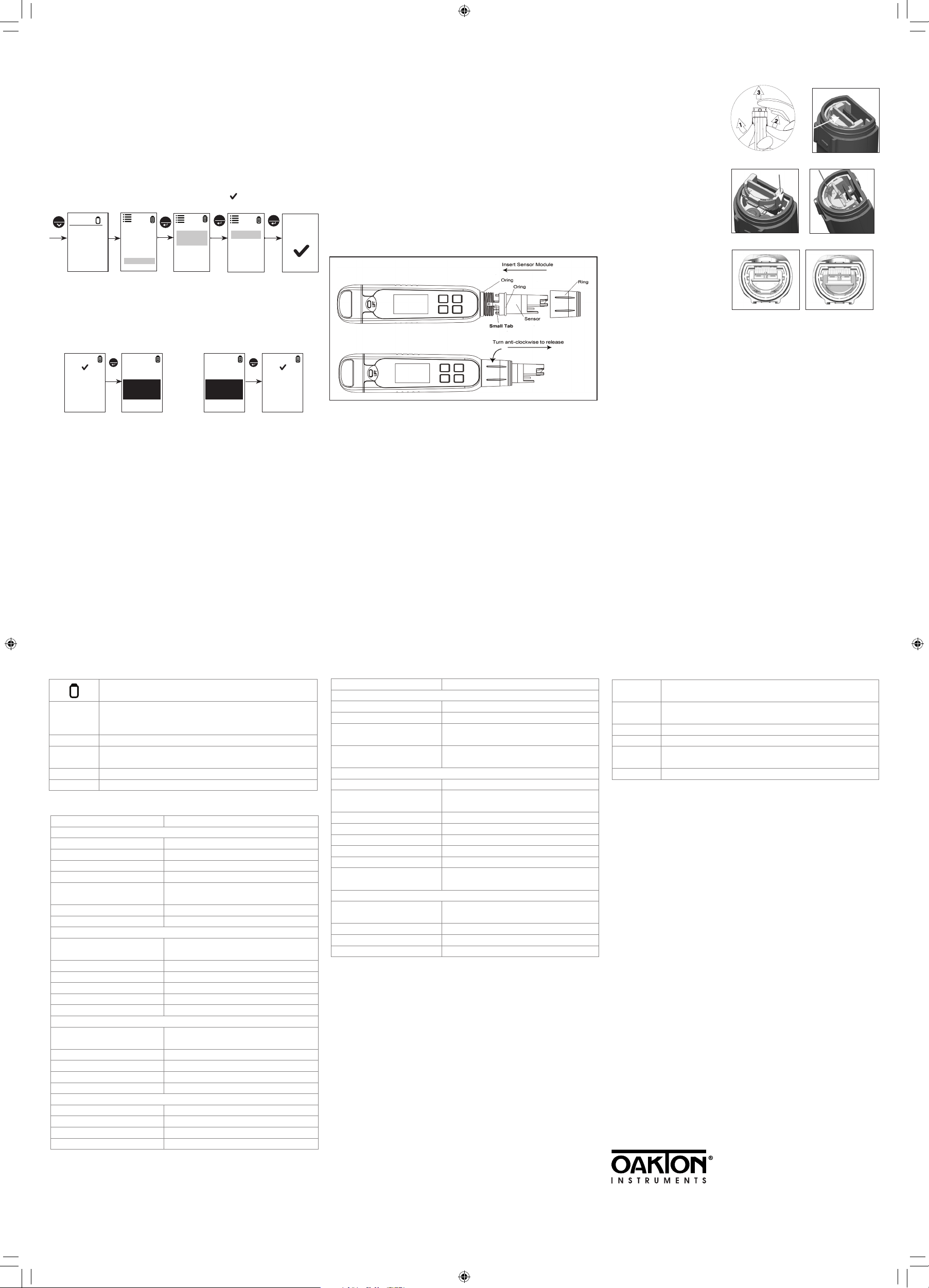
Sensor Replacement
You can replace the sensor module at a fraction of the cost
of a new tester. When the tester fails to calibrate or gives
fluctuating readings in calibration standards, you need to
change the electrode.
1. With dry hands, grip the ring with sensor facing you.
Twist the ring counterclockwise. Save the ring for later use.
2. Pull the old sensor module away from the tester.
3. Align the four tabs on the new module so that they
match the four slots on the tester.
4. Gently push the module onto the slots to sit it in position.
Push the smaller O-ring fully onto the new sensor
module. Push the other O-ring over the module and
thread it into place by firmly twisting clockwise.
Note: It is necessary that you recalibrate your tester prior
to measurement after a sensor replacement.
Replacing the Batteries
The PCTSTestr 50 Pocket Tester uses four AAA 1.5 V batteries.
1. To remove the battery
cover, see Figure 1.
Clear the front catch
and then the back
catch, before sliding
the cover off.
2. To remove the battery
plate, push the center
tab towards the front
Fig. 1: Removing battery cover
Fig. 2: Push to unlock
of the tester as shown
in Figure 2. Once
unlocked, remove the
plate to access the
batteries.
3. Invert the tester
upside down to
remove the batteries.
Fig. 3: Align tabs
Fig. 4: Push down to lock
Each side uses two
AAA batteries. Orient
each battery with
positive terminal facing
downward.
4. To lock the battery
place, align the small
Fig. 5: Battery plate unlocked Fig. 6: Battery plate locked
tabs (Figure 3) into the
guide ribs on the housing and then press
down. See Figure 4.
Warranty
This instrument is supplied with a warranty against
manufacturing defects for a period of one year from the
date of purchase.
Sensor Maintenance
1. Always keep the sensor electrodes clean. Rinse the
electrodes with de-ionized water and wipe them dry with
clean cloth before storing with its protective cap. For cup
type electrodes, remove the white plastic cup and insert
to thoroughly clean viscous solutions. Note: Never scratch
electrodes with a hard substance.
2. For better performance, soak the electrode in alcohol for
10 to 15 minutes and rinse with de-ionized water before
starting any measurement process. This is to remove dirt
and oil stains on the electrode, which may affect the
accuracy of the measurements.
7 8 9
Self-Diagnostic Messages
Batteries are weak and need replacement soon.
Appears when calibration is attempted but the reading
stable error
is not yet stable. Wait for the reading to stabilize or
manually confirm the calibration by pressing enter.
buffer error The buffer is outside of the calibration range.
slope error
The 2nd and 3rd calibration point is not within 80% to
120% slope range.
over range The reading is above the measuring range of tester.
under range The reading is below the measuring range of tester.
Specifications
Specifications PCTSTestr 50
pH
pH range –1.00 to 15.00 pH
Resolution 0.01 pH
Relative accuracy ±0.01 pH
Calibration points Up to 3 points
Buffer set standard
selection
Calibration window ±1.00 pH
Calibration type Point to point
Conductivity
Conductivity range
Resolution 0.1 μS, 1 μS, 0.01 mS
Relative accuracy ±1% full scale
Normalization temperature 25.0ºC (77ºF)
Temperature co-efficient 0.0% to 10.0%
Calibration points Up to 3 points
TDS
TDS range
Resolution 0.1 ppm, 1 ppm, 0.01 ppt
Relative accuracy ±1% full scale
Calibration points Up to 3 points
TDS factor 0.40 to 1.00 (selectable)
Salinity
Salinity range 0.00 to 10.00 ppt
Resolution 0.10 ppt
Relative accuracy ±1% full scale
Calibration points 1
USA: 4.01/7.00/10.01
NIST: 4.01/6.86/9.18
0.0 to 200.0 μS, 200 to 2000 μS,
2.00 to 20.00 mS
0.0 to 100.0 ppm, 100 to 1000 ppm,
0.10 to 10.00 ppt (TDS factor 0.5)
Specifications (cont.) PCTSTestr 50
Temperature
Temperature range 0 to 60°C (32.0 to 140.0°F)
Temperature resolution 0.1°C / 0.1°F
Temperature accuracy
Temperature
compensation
From 0 to 50ºC (±0.5°C / ±0.9°F + 1 LSD);
from 50 to 60°C (±1.0ºC / ±1.8°F + 1 LSD)
Yes (Automatic Temperature
Compensation)
General
Display Graphics, dot matrix 80 x 100 pixel
Backlight
Yes, selectable
(30 sec from last key press)
Auto off 8.5 minutes (from last key press)
Reset User / Factory
Power requirement Four AAA 1.5 V batteries
Battery life >150 hours
Water proofing IP67
Regulatory
certifications
CE, FCC
Environmental Operating Conditions
Ambient operating
temperature
5 to 45°C / 41 to 113°F
Relative humidity 5% to 85% noncondensing
Storage temperature –20 to 60°C / –4 to 140°F
Storage humidity 5% to 85% noncondensing
Return of Items
Authorization must be obtained from your distributor
before returning items for any reason. When applying for
authorization, please include information regarding the
reason the item(s) are to be returned.
We reserve the right to make improvements in design,
construction and appearance of products without notice.
Prices are subject to change without notice.
Accessories
Ordering
Code
35634-35
35634-37 Replacement sensor module for PCTSTestr 50
35634-09 Replacement sensor cap
09376-00
17101-45 NIST-traceable calibration with data for pocket testers
Product Description
PCTSTestr 50 pocket tester with case, lanyard,
and batteries
Replacement alkaline batteries; AAA, 1.5 V.
Pack of 12
www.4oakton.com
1065O100_MAN_35634-35 August, 2017
10 11
1065O100_MAN_35634-35.indd 2 9/5/2017 3:09:48 PM
 Loading...