

Oakley TM3030 Owner's Manual

Oakley Sound Systems
TM3030
PCB Issue 3
Builder's Guide
V3.3
Tony Allgood
Oakley Sound Systems
CARLISLE
United Kingdom
Introduction
This is the Builder’s Guide for the issue 3 TM3030 sound module from Oakley Sound. This
document contains a basic introduction to the board, a full parts list for the components
needed to populate the board or boards, and a list of the various interconnections,
For the User Manual which contains an overview of the operation of the unit and the
calibration procedure please visit the main project webpage at:
http://www.oakleysound.com/tm3030.htm
For general information regarding where to get parts and suggested part numbers please see
our useful Parts Guide at the project webpage or http://www.oakleysound.com/parts.pdf.
For general information on how to build our modules, including circuit board population,
mounting front panel components and making up board interconnects please see our generic
Construction Guide at the project webpage or http://www.oakleysound.com/construct.pdf.
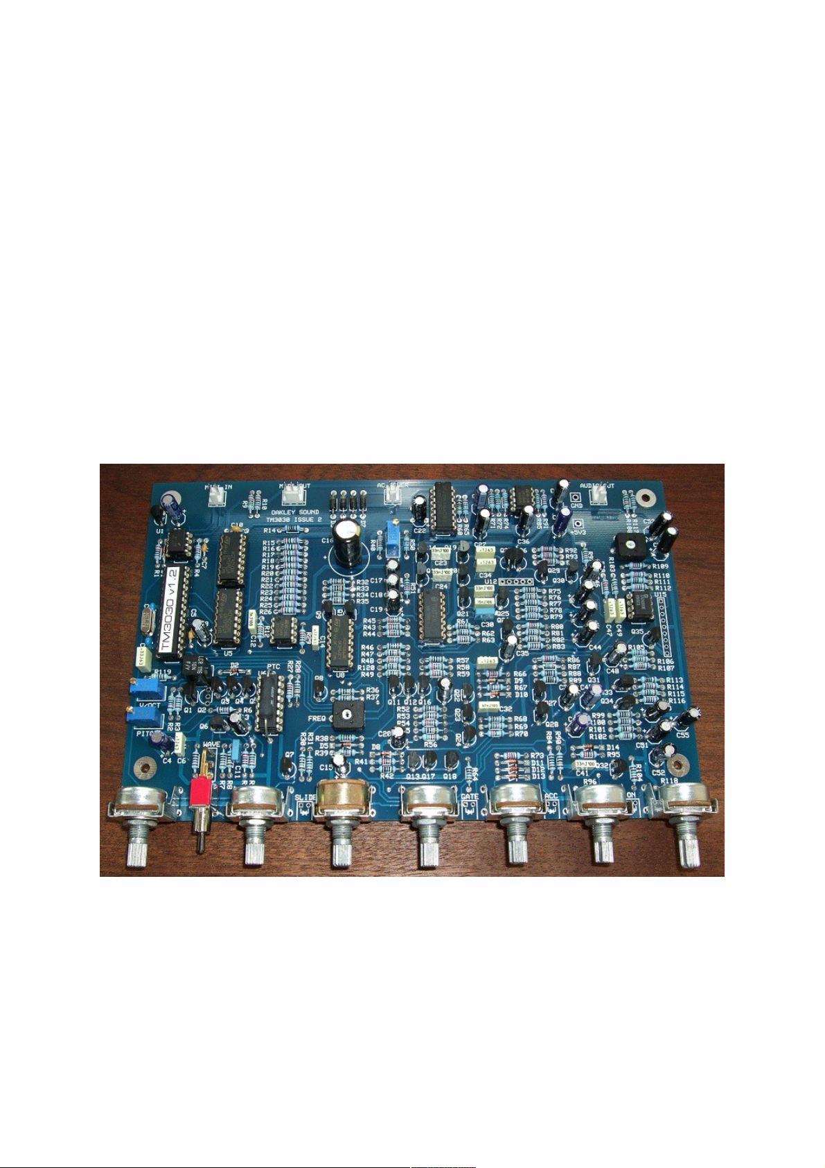
An issue 2 board awaiting its case and LEDs. This one has been built with a matched BC550B pair in the
VCF and a CA3080 and discrete buffer for the VCA. Issue 3 is almost identical.
2

Parts Information
For general information regarding where to get parts and suggested part numbers please see
our useful Parts Guide which is linked from the TM3030 project webpage or direct at:
http://www.oakleysound.com/parts.pdf.
Some special considerations for this project
I recommend to use a close tolerance polystyrene for the VCO timing cap, C9. This will give
better pitch stability. Use a cheaper part if you can accept a small drift in VCO pitch with time.
The PCB is laid out to accept the superbly specified 10nF LCR type EXFS/HR series.
Standard axial polystyrene types will fit into the board if mounted on one end. The working
voltage can be quite low, 63V is common.
Other alternatives to polystyrene are polypropylene. But make sure you get low voltage types
like 63V or so. Polypropylene capacitors are also used in suppression and can get very very
big.
The three ceramic capacitors should be ‘low-K', NP0, or C0G ceramic plates or dipped
ceramics. The lead spacing is 2.5mm.
I have also used some axial multilayer ceramics for the power supply decoupling on the digital
sections. These parts can be substituted with ordinary low voltage radial polyesters if you
wish. Watch out for the pitch spacing as the board is laid out to accept 0.3", 7.5mm, for these
devices.
The horizontal preset or trimmer resistors are just ordinary carbon types. No need to buy the
expensive cermet types for these positions. Carbon sealed units have more resistance to dust
than the open frame types. Piher make a suitable type to use here. Pin spacing is 0.2” at the
base, with the wiper 0.4” away from the base line.
The multiturn trimmers are the ones that have the adjustment on the top of the box. Spectrol
and Bourns make these. Some types are 22 turns, while others are 25 turns. Either will do.
They should have three pins that are in a line at 0.1” pitch. Don’t chose the 10-turn ones with
the adjustment on the end, they won’t fit on the PCB.
With the exception of the differential amplifier in the filter (Q36 & Q37) all the transistors
shown as BC549 on the schematic can be pretty much any NPN transistor that corresponds to
the same pin out. For example: BC550, BC548, BC547 etc. However, I recommend using
BC549 or BC550 as these are low noise devices. A BC550 is actually just a BC549 that can
operate at a slightly higher voltage. Quite often you see an A, B or C suffix used, eg.
BC549C. This letter depicts the gain or grade of the transistor (actually hfe of the device). The
TM3030 is designed to work with any grade NPN devices although I have used BC550B in
my issue 2 prototype.
3

The PNP transistors shown as BC559 on the schematic should be high gain BC559C or
BC560C types.
The SCR in the VCO uses different transistors. Here I have used BC212L and BC182L.
Although these are actually pretty ordinary transistors, they have a different pin out to the
other NPN and PNP transistors used in the TM3030. They also have the same pin out as the
Japanese parts used in the original device. You could substitute these three transistors with the
Japanese parts if you can get them. The BC212L is equivalent to the 2SA733P, and the
BC182L is equivalent to the 2SC536F. It is in my opinion that there are no sonic differences
between the European and Japanese parts in this part of the circuit. Note that the BC212 and
BC182 cannot be used as they are as they have a different pin out to the BC212L and
BC182L.
The FET buffer of the VCO can be one of two parts. The PCB is laid out for both, but you
must ensure the one you use goes into the correct place on the board. Q1 should be a
2SK30A-O. Q2 should be a J201. Do not fit both. The original design and my own TB3030
used the 2SK30A-0 but these are quite tricky to find. In the TB3031 I used the J201, and I
still think this is a very good substitute for the Japanese part. In fact, it's possibly more
accurate since the variation between any two J201 devices may well be less than that of any
two 2SK30A-0.
I will leave the choice of device to you. However, I have tested both parts in the TM3030 and
recorded and compared the resultant audio output. I cannot tell the difference in the outputs
from the two types.
Q18 is also a 2SK30A-Y device. You should seek out this part if you want the envelopes to
behave in the same way as the original. Y types are easier to get hold of than O types and
various places sell them on line although the easiest place to buy is probably Ebay.
As we have seen the original design used two variants of the 2SK30A, the O and the Y types.
These two different types differ only by their value of Idss. This is the current that runs
through the device when the gate and source are grounded and the drain is taken to 10V. The
O types are defined as having a Idss of 0.6mA to 1.4mA. The Y types are defined as having
Idss of 1.2mA to 3.0mA. Look at the range of Idss for the 2SK30A-O. It is interesting to note
this, because the sound of the square wave is dependant on the Idss of the O type device. So
no wonder that people have commented some TB303s sound slightly different to one another.
The original Japanese NPN pair is the 2SC1583. It is a superb component and although not
made any more it is still available from some places. Matched NPN pairs are required in three
places in the TM3030, the exponential convertor, the filter ladder and the differential amp in
the VCF. Only in the differential amplifier have I made space on the board to take the
2SC1583. In the other two positions I have used modern substitutes.
For the exponential converter I have decided to use the more easily available THAT300P in
place of the 2SC1583. There will be no sonic difference here and the THAT array is more
easily affixed to the temp co resistor used in our design.
For the filter ladder the original design uses two matched pairs, one at the bottom of the
ladder, a 2SC1583, and one at the top, a 2SC2291. Although the 2SC1583 is available,
4

getting hold of the 2SC2291 is usually very hard. I didn't want to rely on builders getting this
part so I again have chosen the THAT300P which has been used successfully in the earlier
TM3030 issues and Oakley Diode Superladder modules. The THAT300 is four very well
matched NPN devices in one package. In my tests I found that this part sounds identical to the
Japanese parts and is therefore an excellent substitute.
THAT300P can be obtained from Profusion and Farnell in the UK, Small Bear in the US, and
also at Mouser (part #887-300P14-U). It is a good part but is somewhat expensive.
The differential amplifier of the filter uses a single 2SC1583F in the original design. The
TM3030 allows for this if you can get hold of the 2SC1583. If not, then do not worry, as the
board can also be fitted with a hand matched pair of BC549B, BC550B, BC549C or BC550C
transistors in positions Q36 and Q37. Again, like the FET in the VCO buffer either the two
transistors or the 2SC1583 need to be fitted. Do not fit both U12, and Q36 and Q37.
As stated, if you are fitting them, Q36 and Q37 should be a matched BC549B, BC550B,
BC549C or BC550C pair. This means that both Q36 and Q37 should have identical
characteristics. It is unlikely that two randomly picked NPN transistors will be exactly the
same since the manufacturing process is not that precise. However, it is of my opinion that if
both transistors are of the same type, eg. both BC550C, and are bought new from the same
vendor and at the same time there is a very good chance that they will be matched well enough
for this application. Modern fabrication methods are much better than they used to be.
The VCA circuit also allows the builder some choice in the construction. The board is laid out
to accept either the original R-Ohm BA662 OTA chip, the excellent BA662 clone part from
'Open Music Labs', or a my own VCA design based around the CA3080 OTA and a discrete
buffer circuit. I have tested this part of the circuit very thoroughly, and I am convinced there is
little or no perceivable audible difference in the two designs.
It should be said that both OTA chips are now obsolete, but the CA3080 is still available from
many sources. The original BA662 is nigh on impossible to find without paying very high
prices so Open Music Lab's clone is the best bet if you want to go the BA662 route.
In either case, do ensure that you build your board to suit your choice. The 3080 design uses
an additional FET (Q35) and resistor (R118) and neither of these should be fitted if you are
using a BA662 or the new BA662 clone.
For the dual op-amps in the TM3030 I have specified the same parts as used in the original
unit. These are AN6562 devices. They have a very large input voltage range, that includes
zero volts, so they cannot be substituted with more common op-amps like the TL072.
Alternatively you can use the LM358 instead. This is a good part and although it does behave
slightly differently to the AN6562 in some conditions it does not appear to affect the
TM3030's sound in any way.
The AN6562 devices are available from various online places for a modest amount. You need
two of them, one for the VCO circuit, the other for the power supply. The LM358 is more
readily available.
5

The PIC is a special programmed device that is supplied when you buy the PCB. Spare preprogrammed PICs, should you break yours, are also available for a small charge. Neither
Sequentix nor Oakley Sound will provide the firmware separately.
The other semiconductors used in the TM3030 are standard parts that you should be able to
get from your local parts supplier.
The PTC is a 1K +3500ppm/K positive temperature coefficient resistor. This means its
resistance goes up with temperature. It's there to keep the VCO’s frequency relatively stable
as the ambient temperature changes. The PTC I now use for this job is made by KRL in the
US. They can be most easily obtained from Oakley Sound with your PCB or via Thonk.
Other PTCs do exist and good use can be had from the cheaper Meggitt series. Farnell's part
number is 1174306 and Mouser's 279-LT300014T261K0J. It's a 1K +3000ppm/K 900mW
device. The old TB3030 used this part and I thought it was great until I tried the KRL parts. I
can simply say that once fitted the KRL parts give much better tuning stability over a wider
range of temperatures.
Input and output sockets are not board mounted. You can choose whichever type of sockets
you wish. However, to reduce the possibility of earth loops you may be wise to use plastic
sockets for the audio output socket.
The LEDs can be any type, although I recommend the use of standard round 3mm types. You
will need to bend their legs if you want them to stick through the panel. More detail about
mounting the LEDs is given on this later on this document. Many manufacturers do ready
made preformed LEDs in little plastic boxes. These may be perfect for the job, but be careful
that your LEDs have the cathode on the right hand side as you look at the front of the device.
The suggested colours for the LEDs are just that, suggestions. You can chose any colour you
want for any of the LEDs. However, bear in mind blue LEDs and other high efficiency LEDs
may appear to be too bright unless you reduce the current with a bigger current limiting
resistor. The current limiting resistors are R64 for the gate, R84 for accent, R31 for slide and
R104 for the power on LEDs. If your chosen LEDs are too bright simply double the value of
the current limiting resistor, say to 2K2, and see what that looks like.
The front panel switch can be any style if you are not fitting it directly to the PCB. However,
the PCB is designed to use the miniature toggle range from C&K. Ones made by Multicomp
also fit very nicely. The switch should be an ordinary ON-ON switch, sometimes called SPDT.
The C&K types are ‘type 2 horizontal’ non-sealed units. C&K’s part number is
7101MD9AV2BE. Farnell part number: 9575502. Multicomp switches are similar but cheaper
and can also be obtained from Farnell. The Multicomp part number is 1MS1T2B4M7RE.
Farnell sell it as part number: 9473297.
The power on switch will probably be fitted to the rear of the unit if you are using a half rack
case or fitting two TM3030 units in one 1U rack. You can chose any type of switch you fancy,
but I normally go for ones that need a circular mounting hole since these are easier to fit.
6

The power inlet socket should be one to match your choice of wallwart supply. However, it is
important that you chose an insulated design, ie. one made from a plastic housing. It is
imperative that you do not let either of the input power leads connect to the chassis.
Sometimes people like to substitute parts in place of my own recommendations. Feel free to
do this, but remember that there is normally a good reason why I have selected that particular
part. If you do find that, say changing an transistor with another one, makes an improvement,
please do let me know via the our forum at Muffwiggler.com.
7
 Loading...