

Page 1

Oakley Sound Systems
5U Oakley Modular Series
midiDAC
Single Channel midiCV Converter
PCB Issue 4 & 5
User Manual
V5.0
Tony Allgood
Oakley Sound Systems
Carlisle
United Kingdom
Page 2
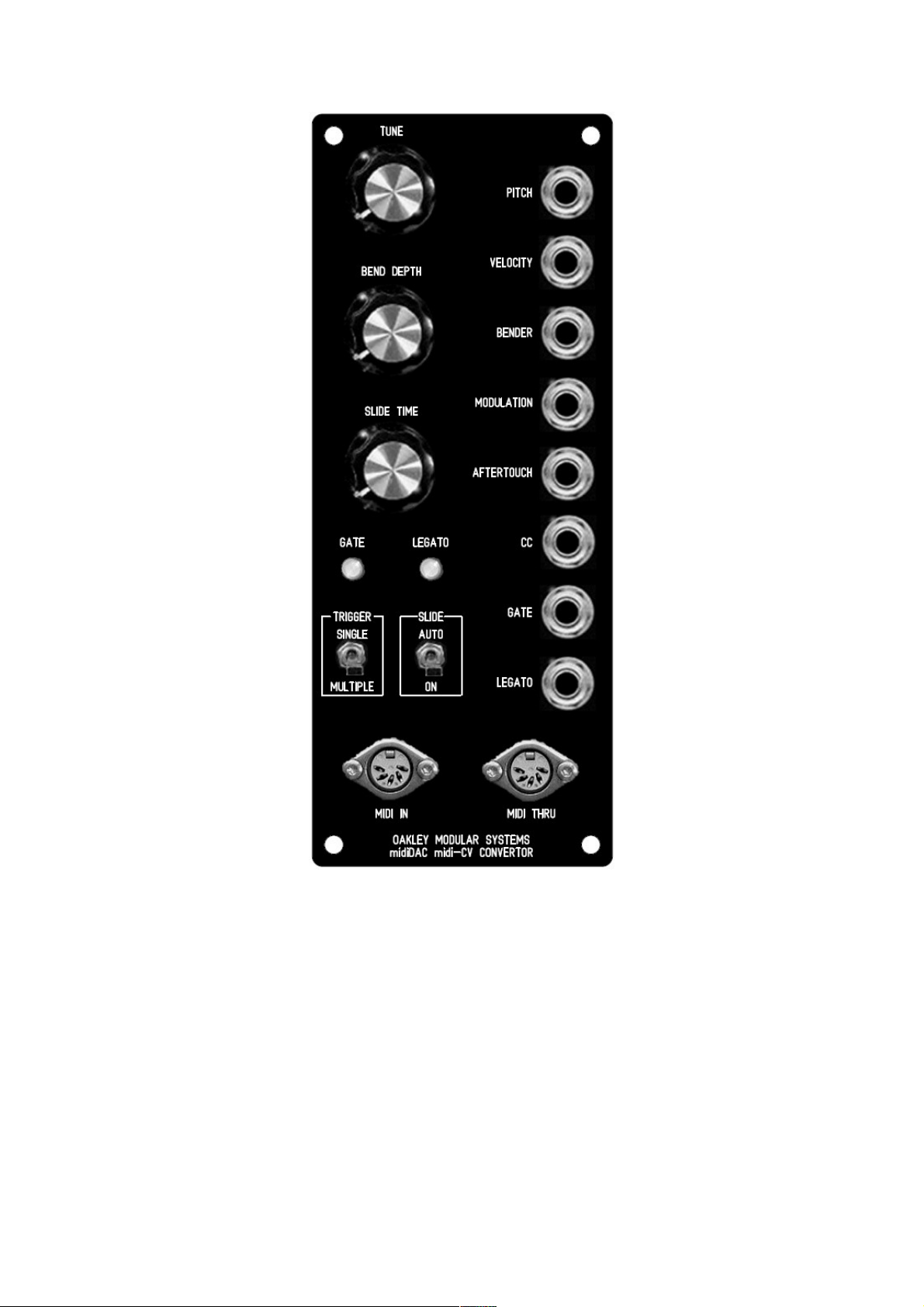
The suggested front panel layout for the 2U wide MOTM format module.
2
Page 3
Introduction
This is the User Manual for the issue 4 and 5 midiDAC midi to CV convertor 5U module from
Oakley Sound. This document contains an overview of the operation of the unit, the midiDAC
PIC specifications and the calibration procedure.
For the Builder's Guide, which contains a basic introduction to the board, a full parts list for
the components needed to populate the boards, and a list of the various interconnections,
please visit the main project webpage at:
http://www.oakleysound.com/mididac.htm
For general information regarding where to get parts and suggested part numbers please see
our useful Parts Guide at the project webpage or http://www.oakleysound.com/parts.pdf.
For general information on how to build our modules, including circuit board population,
mounting front panel components and making up board interconnects please see our generic
Construction Guide at the project webpage or http://www.oakleysound.com/construct.pdf.
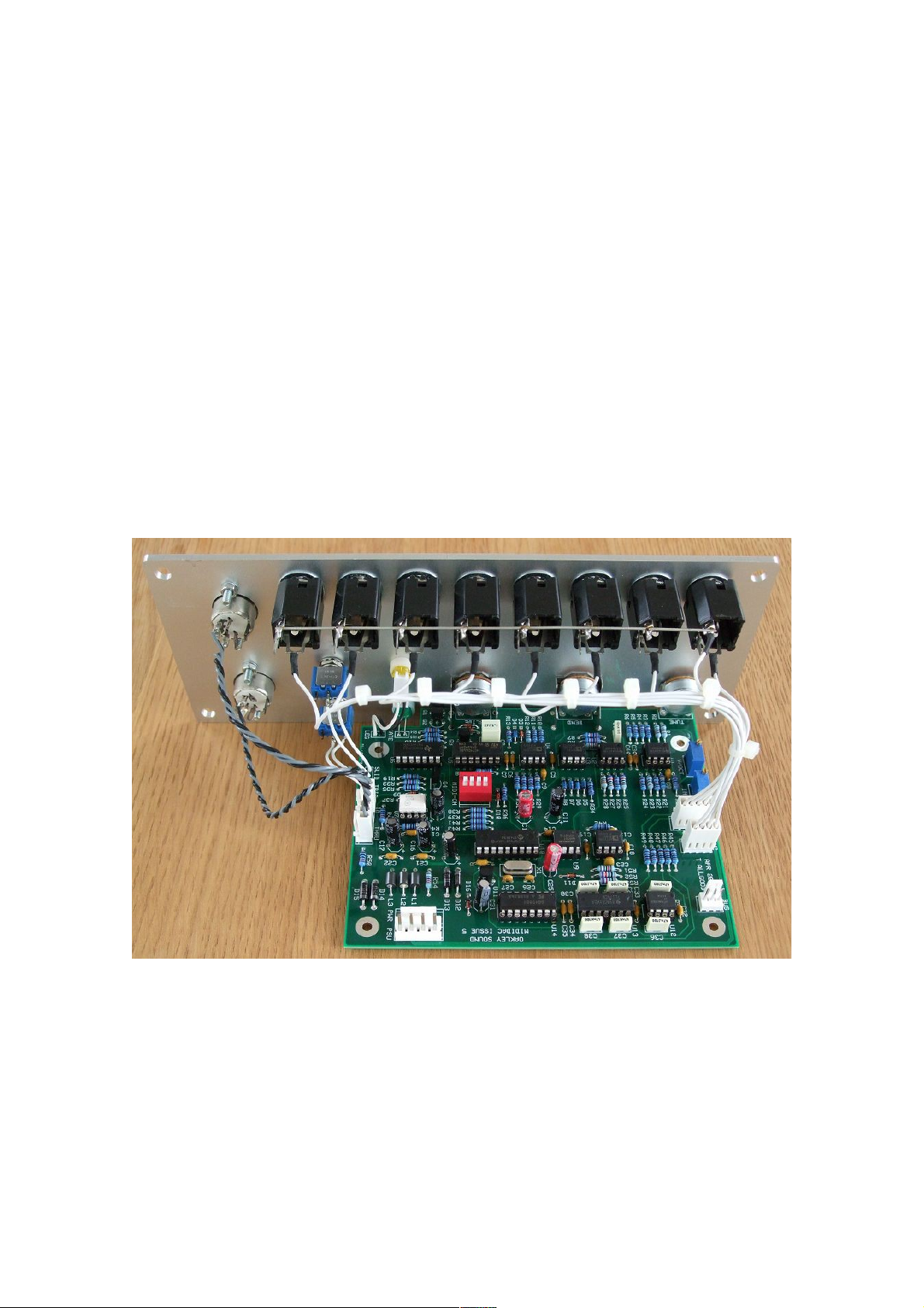
The issue 5 midiDAC fitted to a 2U wide natural finish Scheaffer panel.
3
Page 4

The Oakley midiDAC midi to CV convertor module
The midiDAC is a single channel midi to analogue convertor. This project is a joint
development between Oakley Sound and Trevor Page. Trevor wrote the firmware for the
processor used in this project.
The midiDAC is designed to drive any 1V/octave synthesiser or modular system. There are
eight outputs available:
Gate: +5V gate
Pitch CV: 127 steps of 12 bit accurate pitch voltage conforming to 1V/octave
(trimmable). Pitch bend is added to this signal and the maximum bend
interval (up to one octave) can be adjusted from the bend depth control.
Velocity: 0 to 10V proportional to midi note on velocity.
Pitch Bend: -5V to +5V proportional to pitch bend wheel position. 0V corresponds to a
centred wheel.
Modulation: 0 to 10V proportional to modulation wheel position.
Aftertouch: 0 to 10V proportional to midi channel aftertouch.
CC # 100: 0 to 10V proportional to midi controller number 100.
Legato: This signal goes to +5V when two notes are played at the same time. This
can allow slides to be activated at will; TB303 style. An optional external
switch may be used to override the automatic activation of slide. Slide may be
turned off by transmitting the standard midi glide/slide command.
Also featured on the circuit board itself is a 3-way header to directly feed the Oakley ‘CVgate’ bus on the Dizzy board.
The design also features a midi thru circuit which is greatly improved on the previous issue
midiDAC designs. The processor used in this project is a PIC16F628 running at 4 MHz.
Please note: this product does not support the use of V/Hz or linear VCOs. These are found
on some Yamaha and Korg analogue products, and just one Roland, the SH-2000.
4
Page 5

Other Features
There is a note stack within the firmware to allow the midiDAC to remember notes pressed.
Thus if two or more notes are pressed at the same time, the oldest notes will be remembered
so that if the more recent notes are removed the pitch will return to the still pressed older
notes.
The midiDAC also includes a TB303 style slide circuit. This can be turned either by engaging
a switch, or by playing two notes at once. The pitch will glide up or down to the most recently
pressed note. A pot can control the speed of the slide.
Note retriggering is an option that can be changed on the fly. A simple switch or link can be
used to select whether it is on or off. Ordinarily, when a note is pressed the gate always goes
high. However, if a second note is pressed while another is still held down, the pitch CV will
change but the gate remains high. The envelope generators on your synth will not retrigger.
This is typical of Moog synthesisers. It can be useful. The 'Retriggering' mode allows the gate
to drop momentarily when any new note note is pressed if there is a note already down. Thus,
when the pitch CV changes, the envelopes will be retriggered, just like a normal note. This
allows fast keyboard runs to be easily achieved.
The new suggested panel layout incorporates both the glide and re-trigger switches.
The midiDAC features a built in midi THRU port. This essentially produces a copy of the midi
input signal which can be then fed to another midi unit. Both the opto isolator and the THRU
buffer are high speed devices so there is minimal skew. Skew, in this case, is the difference in
rise and fall times of the digital midi data stream. Each opto-coupler the midi data has to travel
through will alter the shape of the data waveform. This is sometimes thought of as a delay but
this is not strictly true. What happens is that for each opto-coupler and cable run the midi
signal has to pass through the more skewed the signal will be. Excessive skew will cause data
corruption, eg. notes will be randomly dropped or held, particularly if there is a lot of
information being sent down that midi cable. Opto-couplers also deteriorate with use so have
a limited lifetime. It is therefore not recommended to have long midi chains. Normally just two
or three devices in a row is sufficient.
The module requires a split supply of +/-15V at around +40mA and -30mA. +/-12V operation
is not supported.
5
Page 6

PIC Firmware Data Version 2.2
The PIC could in theory generate 8 output control ‘voltages’ when used with a single DAC
and 8-channel demultiplexer. However, we only use six of them in this version of the
midiDAC firmware:
Output CV generated
1 Pitch CV
2 Modulation Wheel
3 Note on velocity
4 Pitch bender
5 Aftertouch
6 CC 100
7 Reserved
8 Reserved
The PIC also generates two digital type signals direct from its own ports. These are gate and
slide. The former goes low when any note on is received on the selected midi channel and will
go high when a note off, or key velocity zero, is received. It will briefly blip high in the case of
‘legato mode’ off if a second (or third, etc.) note is pressed whilst others are still held down.
The Slide output will go low if more than one note is active on the selected midi channel. The
slide will go high if there are no overlapping notes.
For both logic outputs, it is expected that the PIC will drive NPN inverting stages. This is to
protect the PIC from improper connections to the true slide and gate outputs. It also provides
the facility to level shift upwards very easily.
A third logic output is also available from the PIC that can drive a midi active LED and
suitable current limiting resistor. This feature is unused in the midiDAC module. This output
goes low for 500mS if any valid midi data is present on the midi port.
6
Page 7
Midi Channel selection
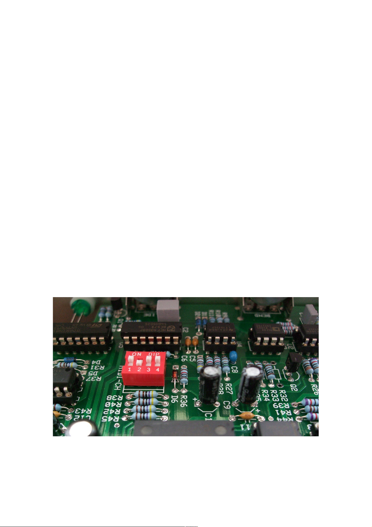
Midi channel is selected by four lines which must be either floating or be grounded. The
simplest way to set midi channel is with a 4-way DIP switch which shorts the data line to
ground. 0 is switch closed (ON) and 1 is switch open (OFF). Binary codes are being read pin 4
to pin 1. Pin 4 is MSB, pin 1 is LSB.
Code Midi Channel
0000 1
0001 2
0010 3
0011 4
0100 5
0101 6
0110 7
0111 8
1000 9
1001 10
1010 11
1011 12
1100 13
1101 14
1110 15
1111 16
For example, to set midi channel 3, set the DIP switch to 0010. That is, 1 on, 2 off, 3 on, 4 on.
This midiDAC is set to receive midi data on channel 3
7
Page 8

Gate Trigger Modes
The midiDAC allows the selection of two gate trigger modes via the ‘Legato mode’ switch.
This is marked on the new PCB as ‘RE-TRIG’. You can connect a simple SPST switch to this
or a simple jumper. The setting of this switch/jumper determines how the gate signal responds
to overlapping notes. Closing this switch, or fitting the jumper, enables multiple gate
triggering for legato playing. This is the re-trig option. The gate signal is taken briefly low at
the start of a new note, even if the fingers haven’t left the keyboard from the previous note.
With the switch open, or leaving the position blank, the gate does not retrigger for
overlapping notes. This is the classic analogue keyboard method and more suitable for those
TB303 slides.
Legato Mode may also be enabled or disabled via the Legato Footswitch MIDI messages. If
these messages are to be used, the Slide Mode switch on the midiDAC unit should remain in
the off position.
midiDAC Implementation of MIDI Controllers
The following table summarises the MIDI controllers supported by the midiDAC firmware.
Hex Dec Midi Controller Definition Implementation on the midiDAC
41h 65 Portamento (Slide) On / Off Switches the portamento (slide)
function
44h 68 Legato Footswitch Controls the gate retrigger mode.
0 to 63 = off, 64 to 127 = on.
78h 120 All Sound Off Silences all notes & clears
accent/gate/slide.
Data byte = 0 for this controller.
79h 121 Reset All Controllers Centres Pitch Wheel and zeroes various
controllers.
Data byte = 0 for this controller.
7Bh 123 All Notes Off Silences all notes & clears
accent/gate/slide.
Data byte=0 for this controller.
7Ch 124 Omni Mode Off Unit responds only to selected MIDI
channel.
Data byte=0 for this controller.*
7Dh 125 Omni Mode On Unit responds to any MIDI channel. Data
byte=0 for this controller.*
7Eh 126 Poly Mode Off All notes cleared*
7Fh 127 Poly Mode On All notes cleared*
* In accordance with MMA specifications, all notes are cleared when these controller
messages are received.
8
Page 9

Note Priority
The midiDAC firmware uses last note priority. That is, it will assign the pitch CV to the last
note to be held. However, all 'overlapped' notes are still retained in memory and are
reactivated in order should the most recent notes to be held be released.
Copyright Notice
Please note: No permission is granted to copy in anyway, or alter, the PIC firmware provided
on the midiDAC PIC. The PIC is copy protected and we ask users not to bypass this
protection. The firmware is not available separately, although pre-preprogrammed PICs are
available from Oakley Sound Systems.
9
Page 10

Calibration
There are two trimmers, V/OCT and INIT, on the midiDAC PCB. Both of them are designed
to allow you to make the midiDAC respond correctly to the rest of the modular system. If you
already have a perfectly tuned and calibrated system, it is best to trim the midiDAC to suit
your system rather than the other way around.
V/OCT
This controls the scaling of the pitch CV output. That is, how much the VCO pitch will
change with every note increment on the controlling keyboard or sequencer.
If you already have a calibrated set of VCOs with your current system it is best to adjust the
midiDAC’s V/OCT trimmer to match your existing set up. Therefore, connect the midiDAC
to one of your VCOs and adjust V/OCT until you get perfect tuning.
Remember altering V/OCT will affect all notes on the keyboard, so you need to be looking at
getting an octave interval between the notes rather than setting absolute pitch of one note. The
INIT trimmer can be adjusted later for setting absolute frequency.
If you do not have an existing system and the midiDAC is your first module, a perfectly
calibrated midiDAC will then ensure that the rest of the system will be true. Connect the
midiDAC to a keyboard, sequencer, or computer midi interface and power up. Allow the
module to settle by leaving it on for ten minutes or so.
Now play the highest C on your controller keyboard. Use the keyboard's octave select buttons
to ensure your controller is set to produce the highest octave. Your keyboard will have sent
one of two notes. Older midi controllers may actually have sent midi note 127 which is G9. If
this is the case you should adjust V/OCT until pin 1 of U1 gives -10.58V (or -10V.583V if
your voltmeter is that accurate). If your controller sent midi note number 120 which is C9 then
you should adjust V/OCT until pin 1 of U1 gives exactly -10.00V.
If you are unsure which note your controller is sending then don't worry. If it's sending G9
you'll be able to get -10.58V easily enough. If it's sending C9 then you won't be able to trim to
-10.58V but you will be able to trim to -10.00V. In either case you should verify that for every
octave you go up the keyboard the voltage on pin 1, U1 changes by -1.00V. That is if C9 is
-10V, then C8 will be -9V, C7 will be -8V and so on.
If you are using a DAW or other midi software program then send the midiDAC note 120 and
adjust V/OCT until pin 1 of U1 gives -10.000V.
If you have an older issue 4 midiDAC you will need to correctly adjust the Tune control on
the front panel before you measure the output U1 pin 1. You need to centralise the Tune
control and ensure that the tune pot's wiper voltage is exactly 0.000V with respect to module
ground (0V). The easiest way to monitor this voltage is to put your meter's red lead, or scope
probe, on the left hand end of R4.
10
Page 11

INIT
This adjusts a controlled voltage offset applied to the pitch CV and sets the range over which
the midiDAC's Pitch CV output operates. Set the TUNE pot on the front panel to its central
position before you start the adjustment of the INIT trimmer. INIT is set so that any
connected VCOs produce the correct note when played from a keyboard or sequencer.
If you have an issue 5 midiDAC with R2 installed then INIT is normally adjusted so that the
Pitch CV output produces 0.000V when a C2 note (midi note number 36) has been sent to the
module.
If you have an issue 4 midiDAC, or issue 5 without R2 installed, then INIT is normally
adjusted so that the Pitch CV output produces 5.000V when a C4 note (midi note number 60)
has been sent to the module.
Final Comments
I hope you enjoy using the Oakley midiDAC midi to CV convertor module.
If you have any problems with the module, an excellent source of support is the Oakley Sound
Forum at Muffwiggler.com. I am on this group, as well as many other users and builders of
Oakley modules.
If you have a comment about this user manual, or have a found a mistake in it, then please do
let me know.
Last but not least, can I say a big thank you to all of you who helped and inspired me. Thanks
especially to all those nice people on the Synth-diy and Analogue Heaven mailing lists and
those at Muffwiggler.com.
Tony Allgood at Oakley Sound
Cumbria, UK
© August 2019
No part of this document may be copied by whatever means without my permission.
11
 Loading...