

Page 1

Oakley Sound Systems
Analogue Delay – ADR30
User Manual
V1.3
Tony Allgood
Oakley Sound Systems
CARLISLE
United Kingdom
Page 2
Introduction
This is the User Manual for the ADR30 Stereo Ensemble module from Oakley Sound. This
document contains an overview of the unit and goes into some detail regarding the operation
of the module. It also contains the calibration instructions.
For the Builder's Guide, which contains a basic introduction to the circuit board and a full
parts list for the components needed to populate the board, please visit the main project
webpage at:
http://www.oakleysound.com/ADR30.htm
For general information regarding where to get parts and suggested part numbers please see
our useful Parts Guide at the project webpage or http://www.oakleysound.com/parts.pdf.
For general information on how to build our modules, including circuit board population,
mounting front panel components and making up board interconnects please see our generic
Construction Guide at the project webpage or http://www.oakleysound.com/construct.pdf.
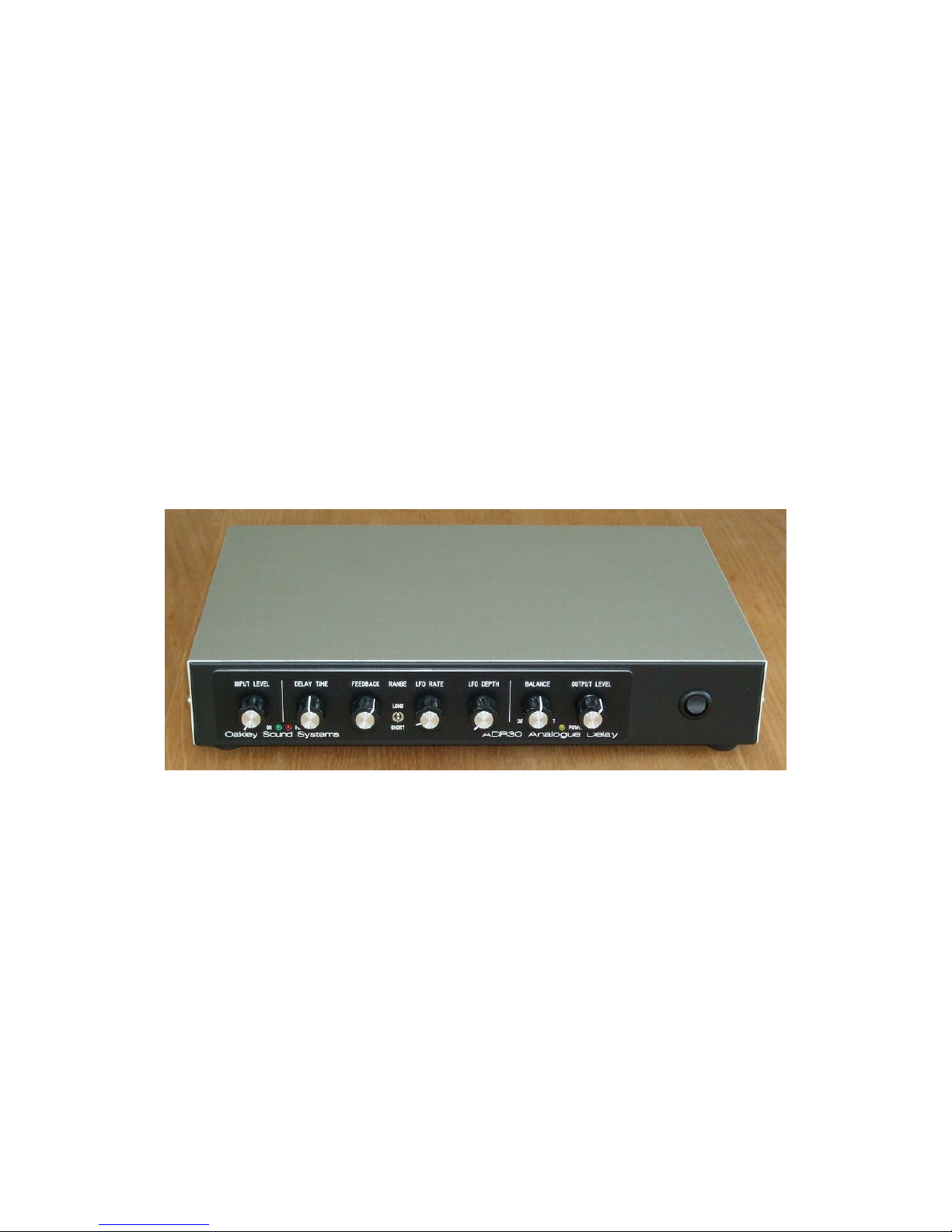
The ADR30 built into a Takachi YM300 case with Schaeffer engraved panel overlay.
2
Page 3

The Oakley Sound ADR30
The Oakley Sound Systems ADR30 is an analogue delay module that processes audio signals
to create echo and chorus effects. It uses two Xvive MN3005 bucket brigade delay (BBD)
integrated circuits to produce a very distinct 'vintage' sound. Classic companding noise
reduction circuitry further add to the sonic characteristics.
Delay time is controlled by a single control on the front panel as well as a built in low
frequency modulation oscillator and/or an external control voltage. With short delay times
using the modulation oscillator can create both subtle and deep chorus effects. A front panel
switch controls whether the signal runs through one or both MN3005 devices. Anti-aliasing
filtering is achieved by two 6-pole discrete switched capacitor low pass filters that track the
delay time, altering audio bandwidth depending on the delay time so that short delays remain
reasonably bright sounding.
The unit is mono but features separate outputs for the wet/dry signal and the delayed signal.
The audio input and outputs are balanced but are compatible with non balanced connections.
A two LED level meter helps you keep signal levels at optimum ensuring a respectable signal
to noise ratio without clipping. The unit will not be damaged by driving the unit into overdrive
and interesting sounds can be obtained by deliberately doing so, either by turning up the input
level or by allowing the feedback to build up to self oscillation.
Although the unit does feature noise reduction circuitry the delay line devices are inherently
noisy and have a very restricted bandwidth. The signal will deteriorate in an interesting manner
as the delay time is increased and/or feedback is heavily applied.
Delay time can be controlled continuously from 15ms to 300ms with one delay stage engaged,
or 30ms to 600ms with both stages engaged.
Audio bandwidth of the delayed signal varies with delay time. The upper cut off frequency
being 10kHz at the shortest delays and 1.5kHz at the longest delays.
The internal triangle wave low frequency oscillator has an approximate range of 0.11Hz to
26Hz.
An external control voltage (CV) can be applied via a dedicated socket on the rear panel to
alter the delay time. A positive voltage will decrease the delay while a negative voltage will
increase the delay. The CV will add to the effects of the internal LFO if applied and the delay
control knob. However, the maximum and minimum delay times of the unit can only be
extended a little in this way.
3
Page 4

Operating Instructions
INPUT LEVEL and LED signal metering
The input level controls the signal running through the ADR30. It affects both the wet and dry
signals. With the pot fully counter clockwise the signal is completely shut off.
The two LED signal meter shows the audio signal level going to the bucket brigade delay
(BBD) circuitry. If the signal is too high then the BBDs will be overdriven and produce
significant distortion. If the signal is too low then the inherent noise produced by the BBD
circuits will become very noticeable. The aim then is to have as large a signal as possible
without introducing too much distortion.
The input level should be set so that the green OK LED is always on when there is signal
present. If the red PEAK LED lights up the BBDs will probably be distorting. However,
depending on the signal that is going through the ADR30, overdriving the BBDs for very
short intervals may be acceptable. Indeed, sonically this can produce some interesting
artefacts. No harm will come to the unit if the unit is run continually in the red.
It should be noted that the input signal is compressed prior to be being sent to the BBDs to
reduce the likelihood of overdriving the BBDs and to improve overall signal to noise ratio.
The signal meter is monitoring the signal after it has been compressed, so the ADR30's meter
will behave slightly differently to normal LED meters such as that found on your audio mixer.
Any compressor takes a certain time to react to the input signal so very fast transient signals
will cause the higher signal LEDs to light even when the apparent volume is quite low. Since
the signal meter monitors the signal going into the BBDs it may be necessary to set the input
level lower for, say, drum loops, than for synth pads, to avoid any unwanted distortion.
With the input level control at maximum the ADR30's limiting circuitry will start to have a
noticeable effect on the audio quality once the input signal rises above 1V(peak to peak). For
most signals the red peak LED will be lit up by then.
DELAY TIME
This controls the delay time of the unit and works in conjunction with the internal LFO and
any external CV. The longest delay time is at the most clockwise point of the control. In other
words turning up the pot increases the delay time. With no external CV and no LFO
modulation applied then the range of this control is either 15ms to 300ms in 'short' mode, or
30ms to 600ms in 'long' mode.
4
Page 5

FEEDBACK
The output of the delay circuitry can be passed back and mixed with the input signal. This
creates repeat delays. Increasing amounts of feedback will increase the volume of the repeats.
It is possible to have the repeat volume louder than the original signal. This creates an rolling
snowball effect – often called self oscillation – by which the final output signal gets louder and
louder until the ADR30's built in signal limiting circuitry takes over. At this point the sound
becomes heavily distorted and develops an interesting character.
An internal trimmer can control the maximum allowable amount of feedback.
It should be noted that the delayed signal's volume is somewhat affected by the delay time.
Therefore, self oscillation may be more readily encountered at certain delay times.
The ADR30 can be produce flanger like sounds with the delay time short and fairly large
amounts of feedback.
RANGE (Switch)
This two position toggle switch determines whether the effected signal runs through one
MN3005 BBD or two MN3005 BBDs. When two devices are selected the signal is delayed
for twice the amount of time it would have been with just one device. LONG selects both
MN3005 devices, while SHORT selects just the one.
For chorus and flanger type effects, which require only small delays, then the short setting is to
be used.
As the signal pathway through a BBD is long and tortuous the audio will be slightly distorted
on the way out. Passing a signal through two such BBDs one after an another will increase
that distortion. Greater fidelity will normally be obtained using the ADR30 in the short setting.
However, it is not quite that simple for longer delays.
The available signal bandwidth, that is, the range of audio frequencies passed by the delay
lines, is controlled by the delay time for each BBD and not the overall delay time of both
devices combined. For example, if you wish to have a 300ms overall delay, then the maximum
bandwidth will be obtained when you have the switch in the long mode. That is, both BBD
devices are being used but being run at half their maximum delay times.
LFO RATE
The ADR30 features an inbuilt low frequency oscillator (LFO) which can modulate, or
control, the delay time. The speed at which the LFO cycles is controlled by this knob. The
speed can be varied from a slow 0.1Hz (one cycle every 8 seconds) to around 26Hz at its
fastest.
Like many famous chorus units the output waveform of the LFO is triangular. This means it
rises in a straight line and falls in a straight line. The rise and fall times are always equal.
5
Page 6

LFO DEPTH
This controls the amount that the internal LFO signal affects the delay time. Increasing this
control will increase the modulation depth, with larger modulation depths causing bigger
changes in the delay time. Note that the maximum and minimum delay times of the ADR30 are
restricted so that excessive swings beyond the limits of the BBDs are not supported. The LFO
works in conjunction with both the Delay Time control and the external CV so it is possible
for the LFO to appear not to be doing anything if the limits of the BBD's delay have already
been reached.
It may seem that increasing modulation depths will produce the greatest effects but this is not
always true. When using the ADR30 to produce chorus effects it is a combination of speed
and depth that creates the desired sound. The chorus effect will be very pronounced even with
small amounts of modulation if the modulation speed is great. Likewise at very slow speeds
you will need to greatly increase the modulation depth to notice a difference.
BALANCE
The ADR30 has two output sockets. One carries the delayed signal that has passed through
the delay lines and all the associated circuitry like the companders and anti-aliasing filters. The
other, the main output, is the mix of the original input signal and the delayed signal.
The Balance control affects the main output signal and adjusts the mix between the unaffected
signal and the one coming from the delay line or lines. DRY is the unaffected signal while
WET is the delayed signal. With the balance control set to dry then the main output socket
will be a copy of the input signal only. With the balance control set to wet then both output
sockets will only have the delayed signal.
Note that the input level control affects both dry and wet signals.
For classic chorus effects the balance is typically set to around 50% so that wet and dry signals
are mixed in equal proportions.
OUTPUT LEVEL
This adjusts the output level of the unit. Both output sockets are controlled by this knob.
The gain of the ADR30 is +6dB when being driven with an unbalanced audio signal and both
input and output level controls set to their maximum.
POWER LED
This will light when power is applied to the unit. To be precise, it lights when the +15V power
supply rail is up and running.
6
Page 7

Input and Output Connections
The ADR30 has both balanced input and output connections. It is expected that the unit will
be fitted with three pole TRS (tip-ring-sleeve) 1/4” sockets. Both input and output are
compatible with unbalanced signals and mono jack plugs can be used without detriment to the
ADR30
It should work well with signal levels direct from a mixer, line level synthesisers and modular
synthesisers. The input impedance is too low to work direct from guitars unless they are fitted
with internal pre-amplifiers.
The maximum input signal level without clipping the pre-amplifier stage is +/-12V. Signal
levels higher than +/-30V have the potential to damage the unit. Input impedance is 44K.
Output impedance is 220R.
The rear panel connections are, from left to right, power input, delay output, mix output, CV input, and
audio input.
7
Page 8

Calibration
There are eight trimmers on the ADR30 main board. It is essential to have access to an
oscilloscope to complete the full calibration routine.
All voltages should be measured with respect to a suitable 0V point. That is the ground lead of
your scope probe should be connected to 0V. 0V is most easily found at the anode of D4 on
the ADR30 main board (ie. the pin of D4 nearest the front of the board)
RANGE This adjusts the range over which the voltage controlled oscillator that directly
controls the delay time operates. Set the ADR30's modulation depth pot to its minimum. Set
the delay time pot to its maximum. Wait a few minutes for the VCO circuitry to stabilise. The
temperature of Q3 will affect the VCO frequency and it heats itself when the frequency is high
so must be allowed to cool before making this adjustment.
Connect the scope probe to pin 1 of U1. There should be a square wave of 0V to 15V here.
Adjust RANGE so that the frequency is approximately 6.5kHz (+/-200Hz).
WIDTH This adjusts the width of the pulse train that controls both sets of switched capacitor
anti-aliasing filters. Connect the scope probe to pin 6 of U3. There should be set of narrow
15V pulses at around 52kHz. Adjust the time base of the scope to 500ns/division so that you
can measure the width of the pulses. Adjust WIDTH so that the width of the pulse at 5V is
approximately 1.2us.
OFF2 & OFF1 These adjust the bias point of the respective BBD line's input signal. If this
voltage offset is set too high or too low then the output signal of that BBD will distort too
easily. The ideal point will be when the signal running through the BBD is at its maximum
without any degradation at the waveform peaks.
Set the range switch to short, and set the delay time pot to its central position. Input a 220Hz
triangle wave or sawtooth wave into the ADR30. Adjust the input level so that the red PEAK
LED is just lit.
Adjust OFF2 so that the waveform seen on your scope at pin 15 of U5 is not clipping at either
the top or bottom of the waveform. Clipping will be seen as an obvious flat lining to the top of
the waveform and a rounding out of the bottom of the waveform. The ideal position of the
OFF2 trimmer will be halfway between the two points that do show clipping. It is best to set
your scope's input mode to AC.
Set the range switch to long. The audio signal will now be going through both BBDs.
Adjust OFF1 so that the waveform seen at pin 15 of U5 is not clipping at either the top or
bottom of the waveform. Again, the ideal position of the OFF1 trimmer will be halfway
between the two points that do show clipping.
8
Page 9

GAIN1 This adjusts the signal volume that comes out of BBD2 which is the BBD we are
listening to when the ADR30 is in short mode.
Set the range switch to short, and set the delay time pot to its central position. Input a 220Hz
triangle wave or sawtooth wave into the ADR30. Adjust the input level so that the red PEAK
LED is just lit.
Connect your scope probe to pin 7 of U16. Adjust GAIN1 so that the signal seen here is the
same amplitude (ie. the peak to peak voltage) irrespective of whether the front panel's Balance
control is either at one end or the other. In other words, adjusting GAIN1 makes the wet
signal to be the same size as the dry signal. You will notice that the wet signal is not quite the
same shape as the dry signal as it has had a long and tortuous journey to get here.
GAIN2 This should be done only after GAIN1 has been correctly set. Connect your scope
probe to pin 7 of U16. Adjust GAIN2 so that the signal seen here is the same amplitude (ie.
the peak to peak voltage) irrespective of the position of the range switch. In other words, you
should adjust GAIN2 so that there is no volume change when listening to the wet signal when
the range switch is changed.
BAL This trimmer adjusts the amount of high frequency clock breakthrough into the audio
output of the final BBD. You want to set this so that the smallest amount of clock is getting
through to the output.
Set your scope's input to AC, the time base to 5uS per division and the scaling to 500mV per
division. Turn the input level down on the ADR30 so that no signal is passing through the
delay lines. Set the delay time control to its middle position. Connect your probe to the emitter
of Q7, which is the right hand pin when the ADR30's pots are facing you.
Adjust the BAL trimmer so that the waveform amplitude seen on the scope trace is minimised.
Set incorrectly you'll see a kind of spiky square wave. Set correctly the trace will reduce to
just a series of spikes.
FBK This adjusts the maximum amount of feedback available from the feedback control knob.
This one is set to taste and it can be set to allow no self-oscillation at all or at the other end to
allow self-oscillation readily. I set mine so that self-oscillation only occurs when the feedback
pot is beyond the 3 o'clock mark.
9
Page 10

Final Comments
I hope you enjoy using the Oakley Sound ADR30.
If you have any problems with the module, an excellent source of support is the Oakley Sound
Forum at Muffwiggler.com.
If you have a comment about this user manual, or have a found a mistake in it, then please do
let me know either via e-mail or the forum.
Tony Allgood at Oakley Sound
Cumbria, UK
© April 2018
No part of this document may be copied by whatever means without my permission.
10
 Loading...