

Page 1
UM11207
NTAG 5 NFC Cockpit application
Rev. 1.0 — 13 August 2020 User manual
622710 COMPANY PUBLIC
Document information
Information Content
Keywords NTAG 5 switch, NTAG 5 link, NTAG 5 boost, NFC, reference application
Abstract Description of NTAG 5 NFC Cockpit application allowing to configure NTAG 5
through NFC interface.
Page 2

NXP Semiconductors
Revision history
Rev Date Description
v.1.0 20200813 Initial version
UM11207
NTAG 5 NFC Cockpit application
UM11207 All information provided in this document is subject to legal disclaimers. © NXP B.V. 2020. All rights reserved.
User manual Rev. 1.0 — 13 August 2020
COMPANY PUBLIC 622710 2 / 25
Page 3

NXP Semiconductors
1 Abbreviations
Table 1. Abbreviations
Acronym Description
ALM Active Load Modulation
EH Energy Harvesting
ED Event Detection
GUI Graphical User Interface
I²C Inter-Integrated Circuit
LED Light Emitting Diode
NFC Near Field Communication
RGB Red Green Blue
SLDA Software License and Distribution Agreement
USB Universal Serial Bus
VCOM Virtual COMmunication
µC micro-Controller
UM11207
NTAG 5 NFC Cockpit application
UM11207 All information provided in this document is subject to legal disclaimers. © NXP B.V. 2020. All rights reserved.
User manual Rev. 1.0 — 13 August 2020
COMPANY PUBLIC 622710 3 / 25
Page 4

NXP Semiconductors
2 Introduction
This document describes NTAG 5 NFC Cockpit application allowing to configure NTAG 5
through NFC interface.
The NTAG 5 NFC Cockpit application is a GUI application running on Windows platform,
connected to NFC reader board over USB.
Currently supported NFC reader boards are PNEV7462C, PNEV5180B and CLEV6630B
running specific NFC Cockpit firmware.
Detailed description of the NTAG 5 NFC Cockpit application can be found in chapter
NTAG 5 NFC Cockpit GUI.
In case of issue running the application, one can find debugging information in related
Troubleshooting chapter.
UM11207
NTAG 5 NFC Cockpit application
UM11207 All information provided in this document is subject to legal disclaimers. © NXP B.V. 2020. All rights reserved.
User manual Rev. 1.0 — 13 August 2020
COMPANY PUBLIC 622710 4 / 25
Page 5
NXP Semiconductors
3 Setup
3.1 Hardware setup
NTAG 5 NFC Cockpit application requires one of the following NFC reader boards
connected over USB.
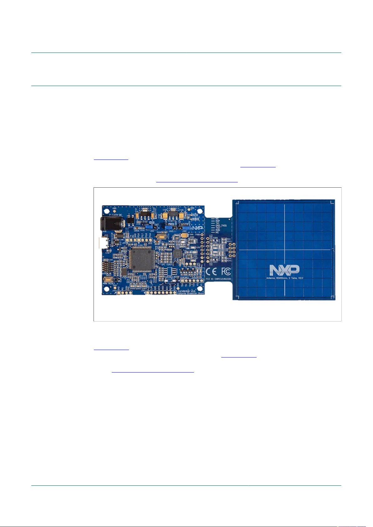
3.1.1 CLEV6630B
CLEV6630B board is CLRC663 plus NFC frontend demo board. To be used with NTAG
5 NFC Cockpit tool, the CLEV6630B board must run NFC Cockpit firmware, this gives
access to CLRC663 plus functionality via virtual COM port (through USB). More details
are given in the board CLEV6630B quick start guide.
UM11207
NTAG 5 NFC Cockpit application
Figure 1. CLEV6630B board
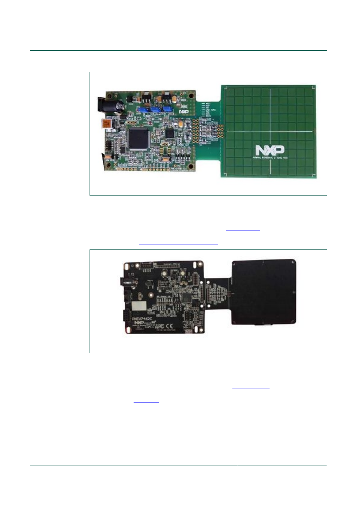
3.1.2 PNEV5180B
PNEV5180B board is PN5180 NFC frontend demo board. To be used with NTAG 5 NFC
Cockpit tool, the PNEV5180B board must run NFC Cockpit firmware, this gives access
to PN5180 functionality via virtual COM port (through USB). More details are given in the
board PNEV5180B quick start guide.
UM11207 All information provided in this document is subject to legal disclaimers. © NXP B.V. 2020. All rights reserved.
User manual Rev. 1.0 — 13 August 2020
COMPANY PUBLIC 622710 5 / 25
Page 6
NXP Semiconductors
Figure 2. PNEV5180B board
3.1.3 PNEV7462C
UM11207
NTAG 5 NFC Cockpit application
PNEV7462C board is PN7462 NFC controller demo board. To be used with NTAG 5
NFC Cockpit tool, the PNEV7462C board must run NFC Cockpit firmware, this gives
access to PN7462 functionality via virtual COM port (through USB). More details are
given in the board PNEV7462C quick start guide.
Figure 3. PNEV7462C board
3.2 Software setup
Installation of the tool is done running NTAG 5 Cockpit installer which can be
downloaded from NTAG 5 development kit webpage (OM2NTx5332). NTAG 5 Cockpit
installer includes both NTAG 5 NFC Cockpit application and NTAG 5 I2C Cockpit
application (see UM11406 for more details).
The installer creates an NTAG5_Cockpit folder (by default under "C:\nxp\" directory)
containing:
• NTAG 5 NFC Cockpit application executable
• a link to the present document on NXP website
• NXP Infrastructure SLDA licensing terms
• related Software Content Register detailing components license details
UM11207 All information provided in this document is subject to legal disclaimers. © NXP B.V. 2020. All rights reserved.
User manual Rev. 1.0 — 13 August 2020
COMPANY PUBLIC 622710 6 / 25
Page 7
NXP Semiconductors
• NTAG 5 I2C Cockpit application executable
• USB-I2C_bridge firmware binary for NXP LPC11U37H MCU
• an executable allowing to uninstall the current package
The installer also allows creating related folder containing shortcuts in Windows Start
Menu, as well as NTAG 5 Cockpit application shortcuts on Windows Desktop.
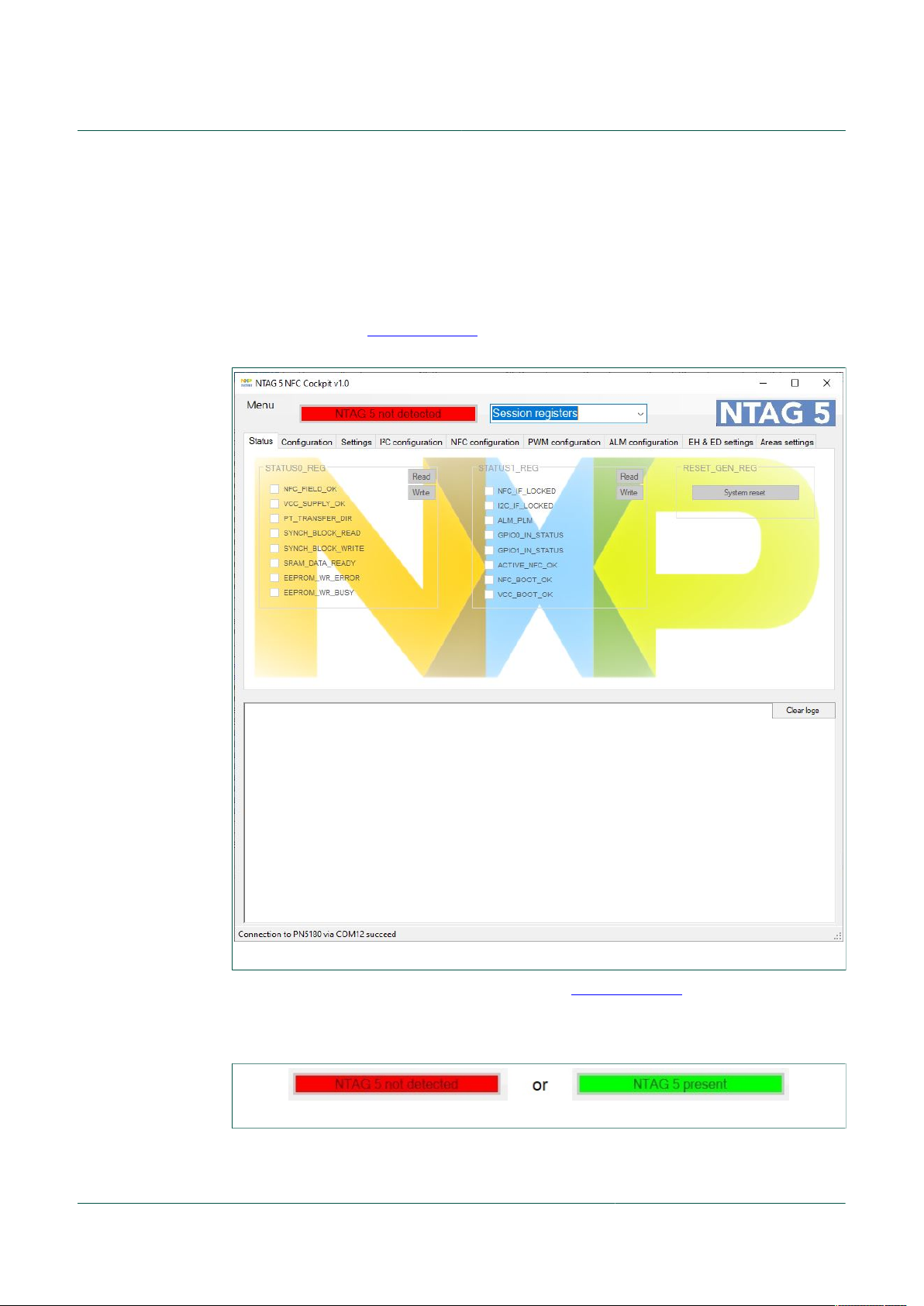
Running the NTAG 5 NFC Cockpit application executable, considering reference setup
depicted in chapter Hardware setup is connected to the computer, shall trigger the
following window to open:
UM11207
NTAG 5 NFC Cockpit application
Figure 4. NTAG 5 NFC Cockpit aspect
If not, please refer to the troubleshooting chapter Troubleshooting.
NTAG 5 NFC Cockpit is continuously scanning for NFC detection of NTAG 5, the
presence of the NTAG 5 is then displayed in the related field.
Figure 5. NTAG 5 detection
Obviously, no operation can be done until NTAG 5 has been detected.
UM11207 All information provided in this document is subject to legal disclaimers. © NXP B.V. 2020. All rights reserved.
User manual Rev. 1.0 — 13 August 2020
COMPANY PUBLIC 622710 7 / 25
Page 8
NXP Semiconductors
4 NTAG 5 NFC Cockpit GUI
The purpose of the current chapter is to describe the NTAG 5 NFC Cockpit tool in details.
4.1 Registers selection
The "Register selection" item allows defining which register bank applies to the "Tabs"
items.
Indeed NTAG 5 registers are split between "Configuration registers" (from 1000h to
109Fh in Configuration memory) and "Session registers" (from 10A0h to 10AFh in
Configuration memory).
Pay attention that "Session registers" settings apply to the current session (apply as soon
as set) while "Configuration registers" settings only apply to the next session (apply after
Power On Reset).
UM11207
NTAG 5 NFC Cockpit application
Figure 6. Registers selection
4.2 Tabs
"Tabs" items exposes NTAG 5 registers definition allowing to set and get NTAG 5 IC
configuration. Detailed registers definition is given in NTAG 5 data sheet for reference.
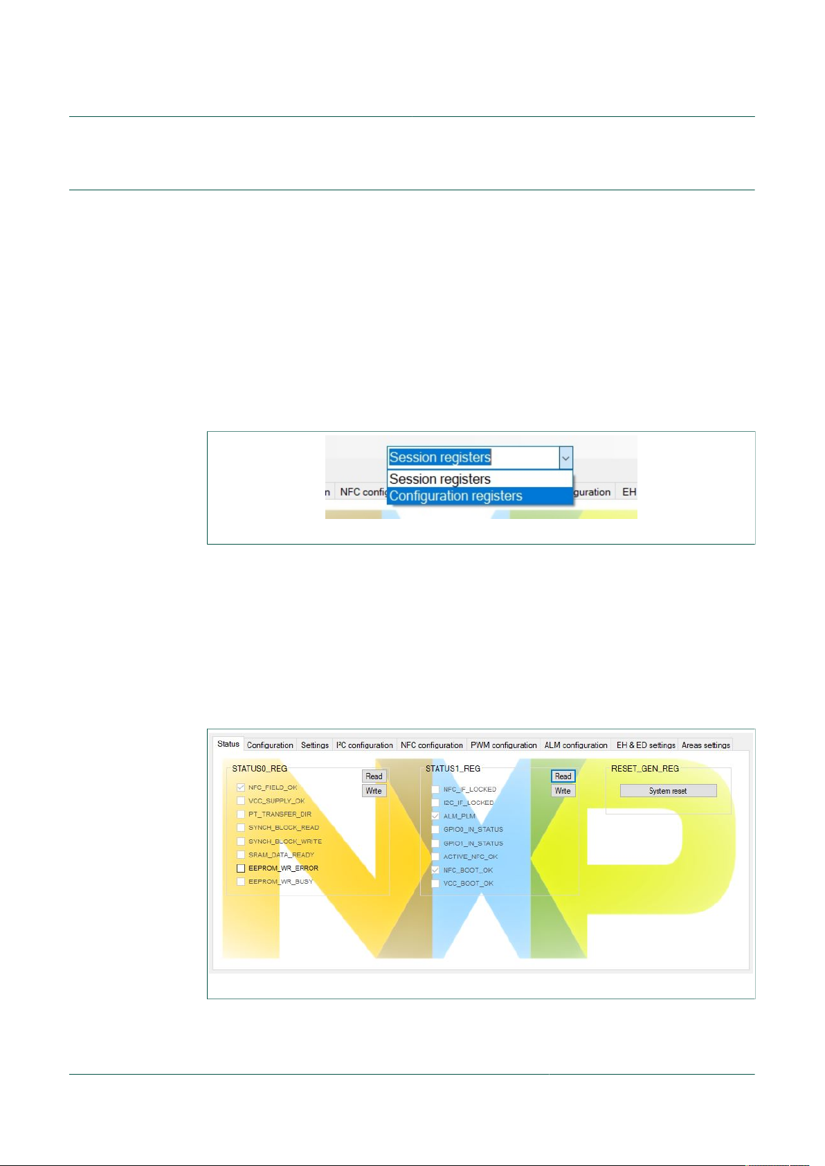
4.2.1 Status
"Status" tab is only valid for "Session registers" since the related registers are only
defined for this memory area.
Figure 7. "Status" tab
STATUS0 and STATUS1 registers writeable bits (not grayed ones) can only be written to
0, clearing the related information.
UM11207 All information provided in this document is subject to legal disclaimers. © NXP B.V. 2020. All rights reserved.
User manual Rev. 1.0 — 13 August 2020
COMPANY PUBLIC 622710 8 / 25
Page 9

NXP Semiconductors
"System reset" button performs software reset of the NTAG 5 IC, thus allowing current
configuration settings being loaded to a new session. This software reset prevents NTAG
5 answering to the NFC command explaining related write configuration error in the log
window.
4.2.2 Configuration
"Configuration" tab has different looks according to the register selection.
UM11207
NTAG 5 NFC Cockpit application
Figure 8. "Configuration" tab for "Session registers" selection
"ARBITER_MODE" setting from "CONFIG1 register" can only be set if
"SRAM_MAPPING" is enabled. Enabling "SRAM_MAPPING is done setting
"SRAM_ENABLE" bit is set in "CONFIG1" register within "Configuration register" area.
Figure 9. "Configuration" tab for "Configuration registers" selection
4.2.3 Settings
"Settings" tab is only valid for "Configuration registers" since the related registers are only
defined for this memory area.
UM11207 All information provided in this document is subject to legal disclaimers. © NXP B.V. 2020. All rights reserved.
User manual Rev. 1.0 — 13 August 2020
COMPANY PUBLIC 622710 9 / 25
Page 10

NXP Semiconductors
Figure 10. "Settings" tab
4.2.4 I²C configuration
UM11207
NTAG 5 NFC Cockpit application
"I²C configuration" tab has different looks according to the register selection.
Figure 11. "I²C configuration" tab for "Session registers" selection
UM11207 All information provided in this document is subject to legal disclaimers. © NXP B.V. 2020. All rights reserved.
User manual Rev. 1.0 — 13 August 2020
COMPANY PUBLIC 622710 10 / 25
Page 11

NXP Semiconductors
Figure 12. "I²C configuration" tab for "Configuration registers" selection
4.2.5 NFC configuration
UM11207
NTAG 5 NFC Cockpit application
"NFC configuration" tab is only valid for "Configuration registers" since the related
registers are only defined for this memory area.
Figure 13. "NFC configuration" tab
"NFC Key Headers" and "NFC Key Privileges" settings can only set if NFC Security
is enabled. "NFC Security" setting is set through "DEV_SEC_CONFIG" register (see
"Settings" tab).
4.2.6 PWM configuration
"PWM configuration" tab has different looks according to the register selection.
UM11207 All information provided in this document is subject to legal disclaimers. © NXP B.V. 2020. All rights reserved.
User manual Rev. 1.0 — 13 August 2020
COMPANY PUBLIC 622710 11 / 25
Page 12

NXP Semiconductors
Figure 14. "PWM configuration" tab for "Session registers" selection
UM11207
NTAG 5 NFC Cockpit application
Figure 15. "PWM configuration" tab for "Configuration registers" selection
4.2.7 ALM configuration
"ALM configuration" tab has different looks according to the register selection.
UM11207 All information provided in this document is subject to legal disclaimers. © NXP B.V. 2020. All rights reserved.
User manual Rev. 1.0 — 13 August 2020
COMPANY PUBLIC 622710 12 / 25
Page 13

NXP Semiconductors
Figure 16. "ALM configuration" tab for "Session registers" selection
UM11207
NTAG 5 NFC Cockpit application
Figure 17. "ALM configuration" tab for "Configuration registers" selection
4.2.8 EH & ED settings
"EH & ED settings" tab has different looks according to the register selection.
UM11207 All information provided in this document is subject to legal disclaimers. © NXP B.V. 2020. All rights reserved.
User manual Rev. 1.0 — 13 August 2020
COMPANY PUBLIC 622710 13 / 25
Page 14

NXP Semiconductors
Figure 18. "EH & ED settings" tab for "Session registers" selection
"Clear Event Detection pin" button trigger clearing the detection pin.
UM11207
NTAG 5 NFC Cockpit application
Figure 19. "EH & ED settings" tab for "Configuration registers" selection
4.2.9 Area settings
"Area settings" tab is only valid for "Configuration registers" since the related registers
are only defined for this memory area.
UM11207 All information provided in this document is subject to legal disclaimers. © NXP B.V. 2020. All rights reserved.
User manual Rev. 1.0 — 13 August 2020
COMPANY PUBLIC 622710 14 / 25
Page 15

NXP Semiconductors
Figure 20. "Area settings" tab
4.3 Logs window
UM11207
NTAG 5 NFC Cockpit application
Bottom area of the NTAG 5 NFC Cockpit tool displays logs:
• In blue: operation details
• In Black: status
• In Green: NFC reader sent data (to NTAG 5)
• In Red: NFC reader received data (from NTAG 5)
Figure 21. Logs window
More detailed information about NFC interface is given in NTAG 5 data sheet.
4.4 Menu
Additional functionalities are accessible through "Menu" item.
Figure 22. Menu
UM11207 All information provided in this document is subject to legal disclaimers. © NXP B.V. 2020. All rights reserved.
User manual Rev. 1.0 — 13 August 2020
COMPANY PUBLIC 622710 15 / 25
Page 16

NXP Semiconductors
4.4.1 Memory view
"Memory view" allows displaying and updating NTAG 5 memory. Values are refreshed
while scrolling.
UM11207
NTAG 5 NFC Cockpit application
Figure 23. Memory view
4.4.2 Memory dump
"Memory dump" offers possibility to read out NTAG 5 memory and store it to a file.
UM11207 All information provided in this document is subject to legal disclaimers. © NXP B.V. 2020. All rights reserved.
User manual Rev. 1.0 — 13 August 2020
COMPANY PUBLIC 622710 16 / 25
Page 17

NXP Semiconductors
Figure 24. Memory dump
Output file content looks like this:
UM11207
NTAG 5 NFC Cockpit application
Figure 25. Memory dump output file content
4.4.3 Memory load
"Memory load" offers possibility to load NTAG 5 memory from data contained in a file.
UM11207 All information provided in this document is subject to legal disclaimers. © NXP B.V. 2020. All rights reserved.
User manual Rev. 1.0 — 13 August 2020
COMPANY PUBLIC 622710 17 / 25
Page 18

NXP Semiconductors
Figure 26. Memory load
The input file must be formatted following below definition for each line (one memory
block of 4 bytes per line):
VVVVh: WW XX YY ZZ where VVVVh is the memory block base address (in
hexadecimal) and WW XX YY ZZ respective values (in hexadecimal) of the memory
block.
UM11207
NTAG 5 NFC Cockpit application
For example: 1041h: 1F 1F 17 14 triggers writing values 0x1F1F1714 at
memory address 1041h (settings ALM_LUT_00, ALM_LUT_01, ALM_LUT_02 and
ALM_LUT_03).
File obtained from "Memory dump" operation (see "Memory dump") can be used as input
to "Memory load" operation.
It is not possible to load content to "Session registers" area (from 10A0h to 10AFh in
Configuration memory) via "Memory Load" operation.
4.4.4 Factory reset
"Factory reset" allows applying default configuration to NTAG 5.
The default configuration is only applied after confirmation from user.
Figure 27. Factory reset
Pay attention that this is done considering the limitation of register access rights
(according to the current configuration some registers may not be writeable).
UM11207 All information provided in this document is subject to legal disclaimers. © NXP B.V. 2020. All rights reserved.
User manual Rev. 1.0 — 13 August 2020
COMPANY PUBLIC 622710 18 / 25
Page 19

NXP Semiconductors
5 Troubleshooting
5.1 NFC reader board not found
While starting NTAG 5 NFC Cockpit tool, in case following issue appears:
UM11207
NTAG 5 NFC Cockpit application
Figure 28. Error NFC reader not found
It indicates that NFC reader board was not properly detected on USB, it should be visible
under device manager as a COM port:
Figure 29. NFC reader device under Device Manager
If not, please refer to the related board quick start guide (PNEV7462C, PNEV5180B or
CLEV6630B).
5.2 Virtual COM port already open
While starting NTAG 5 NFC Cockpit tool, in case following issue appears:
UM11207 All information provided in this document is subject to legal disclaimers. © NXP B.V. 2020. All rights reserved.
User manual Rev. 1.0 — 13 August 2020
COMPANY PUBLIC 622710 19 / 25
Page 20

NXP Semiconductors
UM11207
NTAG 5 NFC Cockpit application
Figure 30. Error COM port already open
It indicates that NFC reader board has been detected on USB but related Virtual COM
port is already open:
• Verify that no other instance of NTAG 5 NFC Cockpit is running
• Check that no other application has an open channel to the NFC reader board-related
COM port.
5.3 Any other issue
For any other issue, refer to [NFC support].
UM11207 All information provided in this document is subject to legal disclaimers. © NXP B.V. 2020. All rights reserved.
User manual Rev. 1.0 — 13 August 2020
COMPANY PUBLIC 622710 20 / 25
Page 21

NXP Semiconductors
6 References
[1] NFC support in NXP community forum
[2] OM27462CDKP: NFC Controller development kit
[3] UM10883 - PN7462 family Quick Start Guide
[4] OM25180FDK: PN5180 NFC Frontend Development Kit for POS Terminal
[5] UM10954 - PN5180 SW Quick start guide
[6] OM26630FDK: CLRC663 plus NFC Frontend Development Kit for Access
[7] AN11022 - CLRC663 Evaluation board quick start guide
[8] NFC-COCKPIT: NFC Cockpit configuration tool for NFC ICs
[9] UM11406 - NTAG 5 I²C Cockpit application
UM11207
NTAG 5 NFC Cockpit application
https://community.nxp.com/community/identification-security/nfc?tid=community
https://www.nxp.com/products/rfid-nfc/nfc-hf/nfc-readers/nfc-controller-developmentkit:OM27462CDKP
https://www.nxp.com/docs/en/user-guide/UM10883.pdf
Applications
https://www.nxp.com/products/rfid-nfc/nfc-hf/nfc-readers/pn5180-nfc-frontenddevelopment-kit-for-pos-terminal-applications:OM25180FDK
https://www.nxp.com/docs/en/user-guide/UM10954.pdf
Management Applications
https://www.nxp.com/products/rfid-nfc/nfc-hf/nfc-readers/clrc663-iplus-i-nfc-frontenddevelopment-kit-for-access-management-applications:OM26630FDK
https://www.nxp.com/docs/en/application-note/AN11022.pdf
https://www.nxp.com/products/rfid-nfc/nfc-hf/nfc-readers/nfc-cockpit-configurationtool-for-nfc-ics:NFC-COCKPIT
https://www.nxp.com/docs/en/user-guide/UM11406.pdf
UM11207 All information provided in this document is subject to legal disclaimers. © NXP B.V. 2020. All rights reserved.
User manual Rev. 1.0 — 13 August 2020
COMPANY PUBLIC 622710 21 / 25
Page 22

NXP Semiconductors
7 Legal information
7.1 Definitions
Draft — A draft status on a document indicates that the content is still
under internal review and subject to formal approval, which may result
in modifications or additions. NXP Semiconductors does not give any
representations or warranties as to the accuracy or completeness of
information included in a draft version of a document and shall have no
liability for the consequences of use of such information.
7.2 Disclaimers
Limited warranty and liability — Information in this document is believed
to be accurate and reliable. However, NXP Semiconductors does not
give any representations or warranties, expressed or implied, as to the
accuracy or completeness of such information and shall have no liability
for the consequences of use of such information. NXP Semiconductors
takes no responsibility for the content in this document if provided by an
information source outside of NXP Semiconductors. In no event shall NXP
Semiconductors be liable for any indirect, incidental, punitive, special or
consequential damages (including - without limitation - lost profits, lost
savings, business interruption, costs related to the removal or replacement
of any products or rework charges) whether or not such damages are based
on tort (including negligence), warranty, breach of contract or any other
legal theory. Notwithstanding any damages that customer might incur for
any reason whatsoever, NXP Semiconductors’ aggregate and cumulative
liability towards customer for the products described herein shall be limited
in accordance with the Terms and conditions of commercial sale of NXP
Semiconductors.
Right to make changes — NXP Semiconductors reserves the right to
make changes to information published in this document, including without
limitation specifications and product descriptions, at any time and without
notice. This document supersedes and replaces all information supplied prior
to the publication hereof.
Suitability for use — NXP Semiconductors products are not designed,
authorized or warranted to be suitable for use in life support, life-critical or
safety-critical systems or equipment, nor in applications where failure or
malfunction of an NXP Semiconductors product can reasonably be expected
to result in personal injury, death or severe property or environmental
damage. NXP Semiconductors and its suppliers accept no liability for
inclusion and/or use of NXP Semiconductors products in such equipment or
applications and therefore such inclusion and/or use is at the customer’s own
risk.
Applications — Applications that are described herein for any of these
products are for illustrative purposes only. NXP Semiconductors makes
no representation or warranty that such applications will be suitable
for the specified use without further testing or modification. Customers
are responsible for the design and operation of their applications and
products using NXP Semiconductors products, and NXP Semiconductors
accepts no liability for any assistance with applications or customer product
design. It is customer’s sole responsibility to determine whether the NXP
Semiconductors product is suitable and fit for the customer’s applications
and products planned, as well as for the planned application and use of
customer’s third party customer(s). Customers should provide appropriate
design and operating safeguards to minimize the risks associated with
their applications and products. NXP Semiconductors does not accept any
liability related to any default, damage, costs or problem which is based
on any weakness or default in the customer’s applications or products, or
the application or use by customer’s third party customer(s). Customer is
responsible for doing all necessary testing for the customer’s applications
and products using NXP Semiconductors products in order to avoid a
default of the applications and the products or of the application or use by
UM11207
NTAG 5 NFC Cockpit application
customer’s third party customer(s). NXP does not accept any liability in this
respect.
Export control — This document as well as the item(s) described herein
may be subject to export control regulations. Export might require a prior
authorization from competent authorities.
Evaluation products — This product is provided on an “as is” and “with all
faults” basis for evaluation purposes only. NXP Semiconductors, its affiliates
and their suppliers expressly disclaim all warranties, whether express,
implied or statutory, including but not limited to the implied warranties of
non-infringement, merchantability and fitness for a particular purpose. The
entire risk as to the quality, or arising out of the use or performance, of this
product remains with customer. In no event shall NXP Semiconductors, its
affiliates or their suppliers be liable to customer for any special, indirect,
consequential, punitive or incidental damages (including without limitation
damages for loss of business, business interruption, loss of use, loss of
data or information, and the like) arising out the use of or inability to use
the product, whether or not based on tort (including negligence), strict
liability, breach of contract, breach of warranty or any other theory, even if
advised of the possibility of such damages. Notwithstanding any damages
that customer might incur for any reason whatsoever (including without
limitation, all damages referenced above and all direct or general damages),
the entire liability of NXP Semiconductors, its affiliates and their suppliers
and customer’s exclusive remedy for all of the foregoing shall be limited to
actual damages incurred by customer based on reasonable reliance up to
the greater of the amount actually paid by customer for the product or five
dollars (US$5.00). The foregoing limitations, exclusions and disclaimers
shall apply to the maximum extent permitted by applicable law, even if any
remedy fails of its essential purpose.
Translations — A non-English (translated) version of a document is for
reference only. The English version shall prevail in case of any discrepancy
between the translated and English versions.
Security — While NXP Semiconductors has implemented advanced
security features, all products may be subject to unidentified vulnerabilities.
Customers are responsible for the design and operation of their applications
and products to reduce the effect of these vulnerabilities on customer’s
applications and products, and NXP Semiconductors accepts no liability for
any vulnerability that is discovered. Customers should implement appropriate
design and operating safeguards to minimize the risks associated with their
applications and products.
7.3 Licenses
Purchase of NXP ICs with NFC technology
Purchase of an NXP Semiconductors IC that complies with one of the
Near Field Communication (NFC) standards ISO/IEC 18092 and ISO/
IEC 21481 does not convey an implied license under any patent right
infringed by implementation of any of those standards. Purchase of NXP
Semiconductors IC does not include a license to any NXP patent (or other
IP right) covering combinations of those products with other products,
whether hardware or software.
7.4 Trademarks
Notice: All referenced brands, product names, service names and
trademarks are the property of their respective owners.
NTAG — is a trademark of NXP B.V.
NXP — wordmark and logo are trademarks of NXP B.V.
UM11207 All information provided in this document is subject to legal disclaimers. © NXP B.V. 2020. All rights reserved.
User manual Rev. 1.0 — 13 August 2020
COMPANY PUBLIC 622710 22 / 25
Page 23

NXP Semiconductors
Tables
Tab. 1. Abbreviations .....................................................3
UM11207
NTAG 5 NFC Cockpit application
UM11207 All information provided in this document is subject to legal disclaimers. © NXP B.V. 2020. All rights reserved.
User manual Rev. 1.0 — 13 August 2020
COMPANY PUBLIC 622710 23 / 25
Page 24

NXP Semiconductors
Figures
UM11207
NTAG 5 NFC Cockpit application
Fig. 1. CLEV6630B board ............................................ 5
Fig. 2. PNEV5180B board ............................................ 6
Fig. 3. PNEV7462C board ............................................6
Fig. 4. NTAG 5 NFC Cockpit aspect ............................ 7
Fig. 5. NTAG 5 detection ............................................. 7
Fig. 6. Registers selection ............................................ 8
Fig. 7. "Status" tab ....................................................... 8
Fig. 8. "Configuration" tab for "Session registers"
selection ............................................................ 9
Fig. 9. "Configuration" tab for "Configuration
registers" selection ............................................ 9
Fig. 10. "Settings" tab ...................................................10
Fig. 11. "I²C configuration" tab for "Session
registers" selection .......................................... 10
Fig. 12. "I²C configuration" tab for "Configuration
registers" selection .......................................... 11
Fig. 13. "NFC configuration" tab ...................................11
Fig. 14. "PWM configuration" tab for "Session
registers" selection .......................................... 12
Fig. 15. "PWM configuration" tab for "Configuration
registers" selection .......................................... 12
Fig. 16. "ALM configuration" tab for "Session
registers" selection .......................................... 13
Fig. 17. "ALM configuration" tab for "Configuration
registers" selection .......................................... 13
Fig. 18. "EH & ED settings" tab for "Session
registers" selection .......................................... 14
Fig. 19. "EH & ED settings" tab for "Configuration
registers" selection .......................................... 14
Fig. 20. "Area settings" tab .......................................... 15
Fig. 21. Logs window ................................................... 15
Fig. 22. Menu ............................................................... 15
Fig. 23. Memory view ................................................... 16
Fig. 24. Memory dump ................................................. 17
Fig. 25. Memory dump output file content .................... 17
Fig. 26. Memory load ................................................... 18
Fig. 27. Factory reset ................................................... 18
Fig. 28. Error NFC reader not found ............................ 19
Fig. 29. NFC reader device under Device Manager ..... 19
Fig. 30. Error COM port already open ..........................20
UM11207 All information provided in this document is subject to legal disclaimers. © NXP B.V. 2020. All rights reserved.
User manual Rev. 1.0 — 13 August 2020
COMPANY PUBLIC 622710 24 / 25
Page 25

NXP Semiconductors
Contents
1 Abbreviations ...................................................... 3
2 Introduction ......................................................... 4
3 Setup .................................................................... 5
3.1 Hardware setup ................................................. 5
3.1.1 CLEV6630B ....................................................... 5
3.1.2 PNEV5180B .......................................................5
3.1.3 PNEV7462C .......................................................6
3.2 Software setup ...................................................6
4 NTAG 5 NFC Cockpit GUI .................................. 8
4.1 Registers selection ............................................ 8
4.2 Tabs ...................................................................8
4.2.1 Status .................................................................8
4.2.2 Configuration ......................................................9
4.2.3 Settings .............................................................. 9
4.2.4 I²C configuration .............................................. 10
4.2.5 NFC configuration ............................................11
4.2.6 PWM configuration .......................................... 11
4.2.7 ALM configuration ............................................12
4.2.8 EH & ED settings ............................................ 13
4.2.9 Area settings ....................................................14
4.3 Logs window ....................................................15
4.4 Menu ................................................................15
4.4.1 Memory view ................................................... 16
4.4.2 Memory dump ..................................................16
4.4.3 Memory load ....................................................17
4.4.4 Factory reset ....................................................18
5 Troubleshooting ................................................ 19
5.1 NFC reader board not found ........................... 19
5.2 Virtual COM port already open ........................19
5.3 Any other issue ................................................20
6 References ......................................................... 21
7 Legal information .............................................. 22
UM11207
NTAG 5 NFC Cockpit application
Please be aware that important notices concerning this document and the product(s)
described herein, have been included in section 'Legal information'.
© NXP B.V. 2020. All rights reserved.
For more information, please visit: http://www.nxp.com
For sales office addresses, please send an email to: salesaddresses@nxp.com
Date of release: 13 August 2020
Document identifier: UM11207
Document number: 622710
 Loading...