

Page 1
QN9080-001-M17
Ultra-low power Bluetooth Smart 4.2 SIP
Rev. 0.1 — 12 March 2018 User Manual
1.
General description
The QN9080-001-M17 is an ultra-low power, high performance surface mount SIP targeted
at Bluetooth Smart applications, enabling users to realize products with minimum time to
market and at the lowest cost. They remove the need for expensive and lengthy
development of custom RF board designs and test suites. The SIPs use NXP’s QN9080001-M17 wireless microcontroller to provide a comprehensive solution with large memory,
high CPU and radio performance and all RF components included. All that is required to
develop and manufacture wireless control or sensing products is to connect a power supply
and peripherals such as switches, actuators and sensors, considerably simplifying product
development.
2.
Features and benefits
Key features:
Bluetooth 4.2 compliant
Integrated antenna
Integrated 32 MHz and 32.768 kHz crystals
Integrated DC-DC circuit
32-bit ARM Cortex-M4F core at 32 MHz
512 kB flash
128 kB RAM
TX power: up to +2 dBm
RX sensitivity: 94 dBm
True single-chip Bluetooth Low Energy (v4.2) SoC solution:
Integrated Bluetooth LE radio, protocol stack and application profiles
Support central and peripherals roles
Support master/slave concurrency
Support 16 simultaneous links
Support secure connections
Support data packet length extension
48-bit unique BD address
94 dBm RX sensitivity
TX output power from 20 dBm to +2 dBm
Very low power consumption:
Single 1.62 V ~3.6 V power supply
1 A power-down mode, to wake up by GPIO
2 A power-down mode, to wake up by 32 kHz sleep timer, RTC and GPIO
3.6 mA RX current at 3 V supply
Page 2
QN9080-001-M17
NXP Semiconductors
QN9080-001-M17
User Manual
All information provided in this document is subject to legal disclaimers.
Rev. 0.1 — 08 Dec 2017
© NXP Semiconductors N.V. 2017. All rights reserved.
2 of 28
Ultra-low power Bluetooth Smart 4.2 SIP
3.4 mA TX current at 0 dBm TX power at 3 V supply
Interface:
32 General-Purpose Input/Output (GPIO) pins, with configurable pull-up/pull-down
resistors
8 external ADC inputs (shared with GPIO pins)
2 Analog Comparator input pins (share with GPIO pins)
Single power supply 1.62 V to 3.6 V
Operating temperature range 40 °C to +85 °C
6 9.7 1.11 mm SIP package
3.
Applications
Ultra-low-power wearable and medical devices with small form factor
Very easy pairing with NFC NTAG
Energy harvesting with the NTAG will allow to create totally new application scenario
the new iOS11 open the NFC reader function, this BLE+NTAG is a perfect match for
that
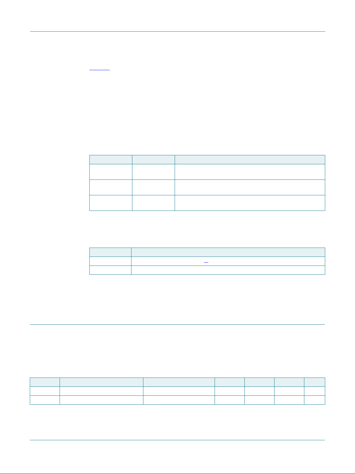
4.
Ordering information
Table 1. Ordering information
Type number
Package
Name
Description
Version
QN9080-001-M17
LFLGA54
SIP SIP in LGA package; body 6 9.7 1.11 mm
SOT1910
AA1
Table 2. Ordering options
Type number
Device order
part number
Flash/KB
Total
SRAM/KB
Cortex-M4
with FPU
FSP
USB FS
GPIO
QN9080-001-M17
3322 960 18570
512
128 1 1 1 32
5.
Marking
QN9080-1-M17
XXXXX
XXXXXXXXXXXX
EtDYYWWXX
Fig 1. QN9080-001-M17 package marking
Page 3
QN9080-001-M17
NXP Semiconductors
QN9080-001-M17
User Manual
All information provided in this document is subject to legal disclaimers.
Rev. 0.1 — 08 Dec 2017
© NXP Semiconductors N.V. 2017. All rights reserved.
3 of 28
Ultra-low power Bluetooth Smart 4.2 SIP
Table 3. Marking code
Line number
Marking code
Line 1
NXP Logo: B&W outline logo
Line 2
part ID: QN9080-1-M17
Line 3
XXXXX: is the STR number request; it will not be mention when we will be on
production
Line 4
XXXXXXXXXXXX: QN batch number
Line 5
• E: TSMC
• t: ASE-K
• D: RoHS indicator (Dark green)
• YY: year; last two digits of year code of assembly
• WW: week code of assembly
• X: C is the QN9080 mask version
• X: for SIP before CQS; it will be removed after
QN9080-001-M17 SIP has the following top-side marking:
Table 4. Device revision table
Revision identifier (R)
Revision description
001
Initial SIP revision
All SIP types have received FCC “Modular Approval”, in compliance with CFR 47 FCC
part 15 regulations and in accordance to FCC public notice DA00-1407. The modular
approvals notice and test reports are available on request.
FCC, IC & Japan ID marking is not mentioned on the package because the device is too
small.
QN9080-001-M17 FCC ID : XXMQN9080M17
QN9080-001-M17 IC ID: 8764A-QN9080M17
QN9080-001-M17 I7 Japan ID:
207-990010
Page 4
QN9080-001-M17
NXP Semiconductors
QN9080-001-M17
User Manual
All information provided in this document is subject to legal disclaimers.
Rev. 0.1 — 08 Dec 2017
© NXP Semiconductors N.V. 2017. All rights reserved.
4 of 28
Ultra-low power Bluetooth Smart 4.2 SIP
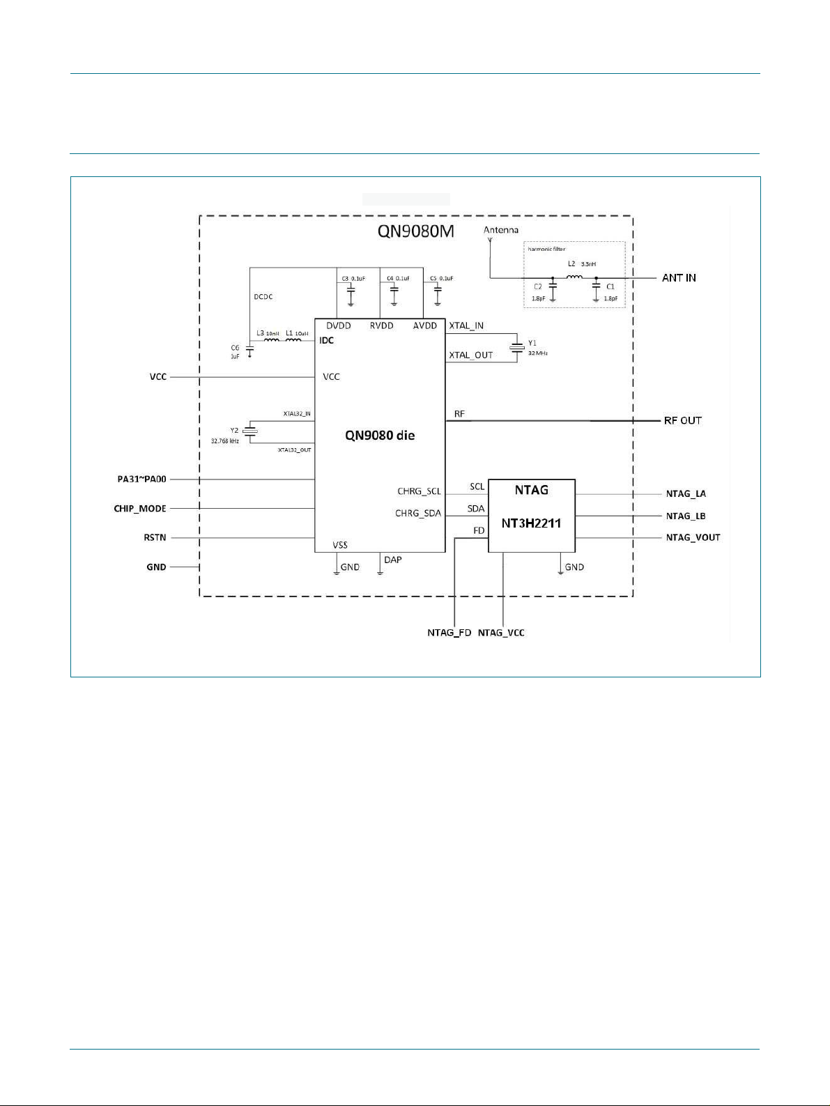
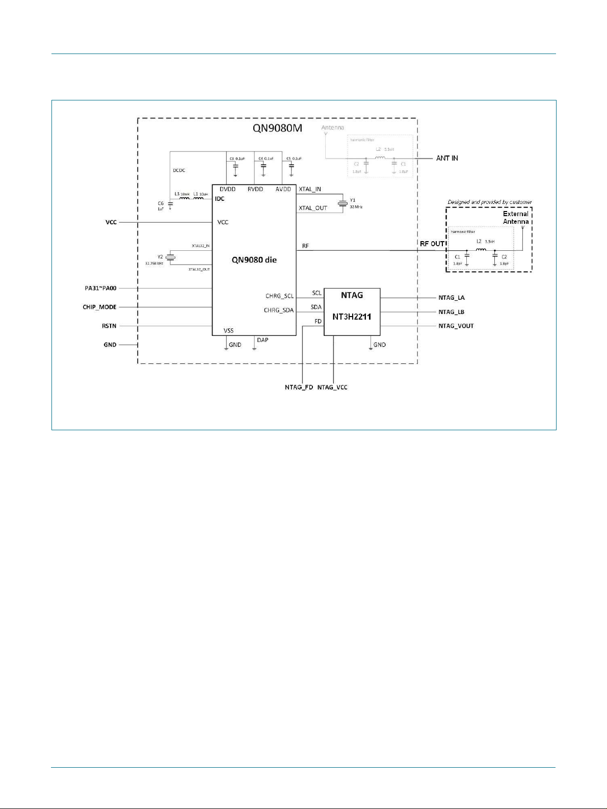
6.
Block diagram
Fig 2. QN9080-001-M17 block diagram
Page 5
QN9080-001-M17
NXP Semiconductors
QN9080-001-M17
User Manual
All information provided in this document is subject to legal disclaimers.
Rev. 0.1 — 08 Dec 2017
© NXP Semiconductors N.V. 2017. All rights reserved.
5 of 28
Ultra-low power Bluetooth Smart 4.2 SIP
QN9080-001-M17 is not certified with external antenna but only with its internal antenna. Customer using external
antenna will have to do new certification.
Fig 3. QN9080-001-M17 block diagram for customer using external antenna (Harmonic filter to be in ad equacy
with customer board)
Page 6
QN9080-001-M17
NXP Semiconductors
QN9080-001-M17
User Manual
All information provided in this document is subject to legal disclaimers.
Rev. 0.1 — 08 Dec 2017
© NXP Semiconductors N.V. 2017. All rights reserved.
6 of 28
Ultra-low power Bluetooth Smart 4.2 SIP
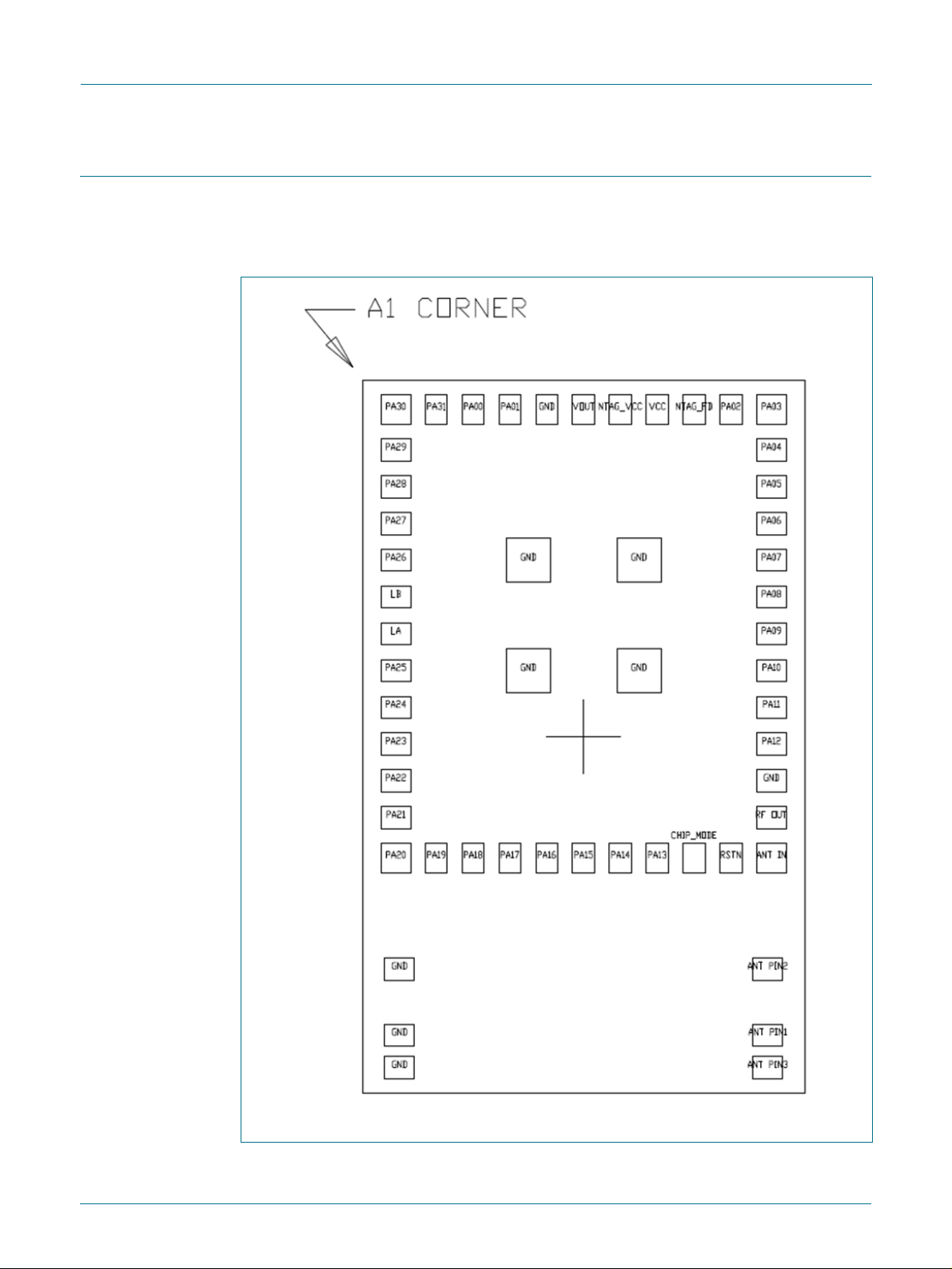
7.
Pinning information
7.1. Pinning
Fig 4. Pin configuration
Page 7
QN9080-001-M17
NXP Semiconductors
QN9080-001-M17
User Manual
All information provided in this document is subject to legal disclaimers.
Rev. 0.1 — 08 Dec 2017
© NXP Semiconductors N.V. 2017. All rights reserved.
7 of 28
Ultra-low power Bluetooth Smart 4.2 SIP
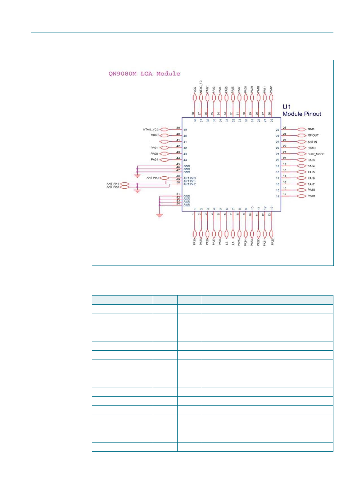
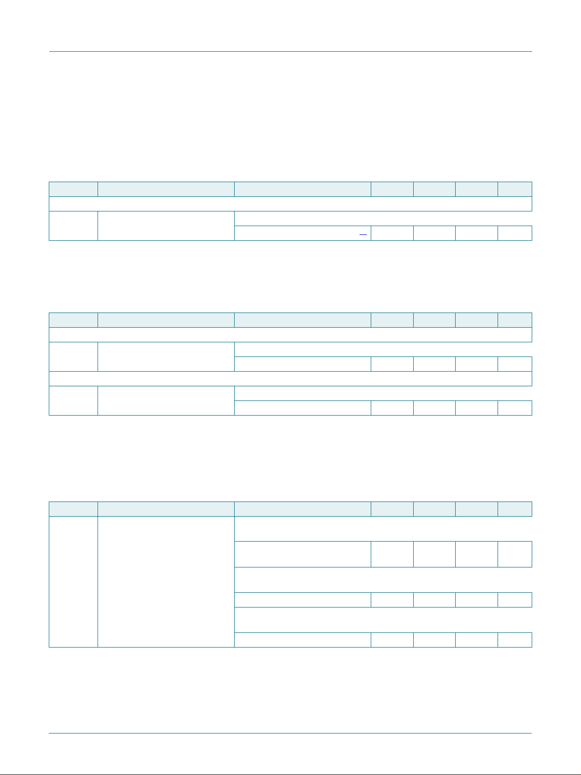
7.2. Pin description
Table 5. Pin description
Symbol
Pin
Type
Description
PA30
1
I/O
GPIO
PA29
2
I/O
GPIO
PA28
3
I/O
GPIO
PA27
4
I/O
GPIO
PA26
5
I/O
GPIO
LB 6 I/O
antenna connection LB
LA 7 I/O
antenna connection LA
PA25
8
I/O
GPIO
PA24
9
I/O
GPIO
PA23
10
I/O
GPIO
PA22
11
I/O
GPIO
PA21
12
I/O
GPIO
PA20
13
I/O
GPIO
PA19
14
I/O
GPIO
PA18
15
I/O
GPIO
PA17
16
I/O
GPIO
GND
Fig 5. SIP pin out
Page 8
QN9080-001-M17
NXP Semiconductors
QN9080-001-M17
User Manual
All information provided in this document is subject to legal disclaimers.
Rev. 0.1 — 08 Dec 2017
© NXP Semiconductors N.V. 2017. All rights reserved.
8 of 28
Ultra-low power Bluetooth Smart 4.2 SIP
Table 5. Pin description …continued
Symbol
Pin
Type
Description
PA16
17
I/O
GPIO
PA15
18
I/O
GPIO
PA14
19
I/O
GPIO
PA13
20
I/O
GPIO
CHIP_MODE
21 I control the chip into different modes
RSTN
22 I hardware reset, active low
ANT_IN
23
I/O
antenna in
RF_OUT
24
I/O
RF output
GND
25 G ground
PA12
26
I/O
GPIO
PA11
27
I/O
GPIO
PA10
28
I/O
GPIO
PA09
29
I/O
GPIO
PA08
30
I/O
GPIO
PA07
31
I/O
GPIO
PA06
32
I/O
GPIO
PA05
33
I/O
GPIO
PA04
34
I/O
GPIO
PA03
35
I/O
GPIO
PA02
36
I/O
GPIO
NTAG_FD
37 O field detection
VCC
38 P power supply
NTAG_VCC
39 P NTAG power supply
VOUT
40 P output supply voltage (energy harvesting)
GND
41 G ground
PA01
42
I/O
GPIO
PA00
43
I/O
GPIO
PA31
44
I/O
GPIO
GND
45 G ground
GND
46 G ground
GND
47 G ground
ANT_PIN3
48 G ground
ANT_PIN1
49 G ground
ANT_PIN2
50 G ground
GND
51 G ground
GND
52 G ground
GND
53 G ground
GND
54 G ground
Page 9
QN9080-001-M17
NXP Semiconductors
QN9080-001-M17
User Manual
All information provided in this document is subject to legal disclaimers.
Rev. 0.1 — 08 Dec 2017
© NXP Semiconductors N.V. 2017. All rights reserved.
9 of 28
Ultra-low power Bluetooth Smart 4.2 SIP
7.2.1 Termination of unused pins
Ta ble 6 shows how to terminate pins that are not used in the application. In many cases,
unused pins should be connected externally or configured correctly by software to
minimize the overall power consumption of the part.
Unused pins with GPIO function should be configured as outputs set to LOW with their
internal pull-up disabled. To configure a GPIO pin as output and drive it LOW, select the
GPIO function in the IOCON register, select output in the GPIO DIR register, and write a 0
to the GPIO PORT register for that pin. Disable the pull-up in the pin’s IOCON register.
In addition, it is recommended to configure all GPIO pins that are not bonded out on
smaller packages as outputs driven LOW with their internal pull-up disabled.
Table 6. Termination of unused pins
Pin
Default state
[1]
Recommended termination of unused pins
RSTN
I; PU
the RSTN pin can be left unconnected if the application does
not use it.
all PAnm
I; PU
can be left unconnected if driven LOW and configured as
GPIO output with pull-up disabled by software
CHIP_MODE
I; PU
can be left unconnected if driven LOW and configured as
GPIO output with pull-up disabled by software
[1] I = Input, IA = Inactive (no pull-up/pull-down enabled), PU = Pull-Up enabled.
7.2.2 Pin states in different power modes
Table 7. Pin states in different power modes
Pin
Active - Sleep - Power Down modes
all PAnm pins
As configured in the SYSCON
[1]
. Default: internal pull-up enabled
RSTN
Reset function enabled. Default: input, internal pull-up enabled
[1] Default and programmed pin states are retained in sleep, and power-down mode.
8.
Characteristics
8.1. Static characteristics
8.1.1 General operating conditions
Table 8. General operating conditions
T
amb
= 40 °C to +85 °C, unless otherwise specified.
Symbol
Parameter
Conditions
Min
Typ
Max
Unit
f
clk
clock frequency
- - 32
MHz
V
CC
supply voltage
1.7 3 3.6
V
8.1.2 Power consumption
Power measurements in active, sleep, power down modes were performed under the
following conditions:
Page 10
QN9080-001-M17
NXP Semiconductors
QN9080-001-M17
User Manual
All information provided in this document is subject to legal disclaimers.
Rev. 0.1 — 08 Dec 2017
© NXP Semiconductors N.V. 2017. All rights reserved.
10 of 28
Ultra-low power Bluetooth Smart 4.2 SIP
• All peripherals disabled
• Analog peripherals (ADC/DAC/ACMP/Capacitive Sense) powered down
• RF off
• 32 MHz HFRCO powered down
Table 9. Static characteristics: Power consumption in active modes
T
amb
= 40 °C to +85 °C, unless otherwise specified.
Symbol
Parameter
Conditions
Min
Typ
[1]
Max
Unit
32 MHz HFXO; DC-DC converter enabled, V
CC
= 3.0 V
I
CC
supply current
CoreMark code executed from Flash
CLK_AHB = 16 MHz
[2]
-
830 - A
[1] Typical ratings are not guaranteed. Typical values listed are at room temperature (25 °C).
[2] Characterized through bench measurements using typical samples.
Table 10. Static characteristics: Bluetooth LE power consumption in active modes
T
amb
= 40 °C to +85 °C, unless otherwise specified.
Symbol
Parameter
Conditions
Min
Typ
[1][2]
Max
[3]
Unit
32 MHz HFXO, CLK_AHB = 8 MHz; Transmitter mode: fc = 2440 MHz
I
CC
supply current
DC-DC converter enabled, V
CC
= 3 V
TX power = 0 dBm
- 4 -
mA
32 MHz HFXO, CLK_AHB = 8 MHz; Receiver mode: fc = 2440 MHz
I
CC
supply current
DC-DC converter enabled, V
CC
= 3 V
94 dBm RX sensitivity
-
4.4 - mA
[1] Typical ratings are not guaranteed. Typical values listed are at room temperature (25 °C).
[2] Characterized through bench measurements using typical samples, with 50 loading on RF port.
[3] Guaranteed by characterization, not tested in production.
Table 11. Static characteristics: power consumption in Sleep mode and Power-down mode
T
amb
= 40 °C to +85 °C, unless otherwise specified.
Symbol
Parameter
Conditions
Min
Typ
[1][2]
Max
[3]
Unit
I
CC
supply current
Sleep mode: all SRAM on, Flash in Standby mode, DC-DC converter
enabled, V
CC
= 3 V
32 MHz HFXO,
CLK_AHB = 16 MHz
-
470
-
A
Power-down mode: 32.768 kHz LFXO on, Flash is powered down, DC-DC
converter disabled, V
CC
= 3 V, T
amb
= 25 °C
8 KB SRAM powered
-
2.6
-
A
Power-down mode: all clocks off, Flash is powered down, DC-DC converter
disabled, V
CC
= 3 V, T
amb
= 25 °C
8 KB SRAM powered
- 1 -
A
[1] Typical ratings are not guaranteed. Typical values listed are at room temperature (25 °C).
[2] Characterized through bench measurements using typical samples.
[3] Guaranteed by characterization, not tested in production.
Page 11

QN9080-001-M17
NXP Semiconductors
QN9080-001-M17
User Manual
All information provided in this document is subject to legal disclaimers.
Rev. 0.1 — 08 Dec 2017
© NXP Semiconductors N.V. 2017. All rights reserved.
11 of 28
Ultra-low power Bluetooth Smart 4.2 SIP
8.2. RF characteristics
8.2.1 Receiver
Table 12. Receiver characteristics
T
amb
= 25 °C; based on characterization; not tested in production. V
CC
= 3 V; fc = 2440 MHz; BER < 0.1 %.
Symbol
Parameter
Conditions
Min
Typ
Max
Unit
S
RX
RX sensitivity
low-power mode with
DC-to-DC converter
-
92 - dBm
P
i(max)
maximum input power
- 0 -
dBm
C/I
carrier-to-interference ratio
co-channel
- 6 -
dB
adjacent channel
at 1 MHz
-
4
-
dB
alternate channel
at 2 MHz
-
41
-
dB
image
image rejection
-
41
-
dB
sup(oob)
out-of-band suppression
30 MHz to 2000 MHz
1
- - dBm
2003 MHz to 2399 MHz
10
- - dBm
2484 MHz to 2997 MHz
10
- - dBm
3 GHz to 12.75 GHz
10
- - dBm
8.2.2 Transmitter
Table 13. Transmitter characteristics
T
amb
= 25 °C; based on characterization; not tested in production. V
CC
= 3 V; fc = 2440 MHz.
Symbol
Parameter
Conditions
Min
Typ
Max
Unit
f
o(RF)
RF output frequency
2400
-
2483.5
MHz
CS
channel separation
- 2 -
MHz
P
o
output power
TX power
20 - +2
dBm
P
o(RF)step
RF output power step
- 1 -
dB
P
o(acc)
TX power accuracy
2 - +2
dB
Page 12

QN9080-001-M17
NXP Semiconductors
QN9080-001-M17
User Manual
All information provided in this document is subject to legal disclaimers.
Rev. 0.1 — 08 Dec 2017
© NXP Semiconductors N.V. 2017. All rights reserved.
12 of 28
Ultra-low power Bluetooth Smart 4.2 SIP
8.3. Analog characteristics
8.3.1 BOD
Table 14. BOD static characteristics
T
amb
= 25 °C; based on characterization; not tested in production.
Symbol
Parameter
Conditions
Min
Typ
Max
Unit
V
th
threshold voltage
interrupt level 0
assertion
-
2.05 - V
de-assertion
-
2.35 - V
reset level 0
assertion
-
1.50 - V
interrupt level 1
assertion
-
2.45 - V
de-assertion
-
2.80 - V
reset level 1
assertion
-
1.85 - V
interrupt level 2
assertion
-
2.70 - V
de-assertion
-
3.10 - V
reset level 2
assertion
-
2.0 - V
interrupt level 3
assertion
-
3.05 - V
de-assertion
-
3.45 - V
reset level 3
assertion
-
2.35 - V
8.3.2 16-bit ADC characteristics
Table 15. 16-bit ADC characteristics
T
amb
= -40 °C to +85 °C; 1.62 V ? V
CC
? 3.6 V; V
REFP
= V
DDA
; V
SSA
= V
REFN
= GND. ADC calibrated at T
amb
= 25 °C.
Symbol
Parameter
Conditions
Min
Typ
Max
Unit
V
I
input voltage range (VINP - VINN)
V
REF
= 1.2 V
-
0.8*VRE
F/(PGA_
GAIN*A
DC_GAI
N)
-
V
REF
= V
CC
-
0.5*VRE
F/(PGA_
GAIN*A
DC_GAI
N)
-
C
i
input capacitance
-
10 - pF
Z
i
input impedance
DC signal, PGA
enabled
>10 - -
k
Page 13

QN9080-001-M17
NXP Semiconductors
QN9080-001-M17
User Manual
All information provided in this document is subject to legal disclaimers.
Rev. 0.1 — 08 Dec 2017
© NXP Semiconductors N.V. 2017. All rights reserved.
13 of 28
Ultra-low power Bluetooth Smart 4.2 SIP
Table 15. 16-bit ADC characteristics …continued
T
amb
= -40 °C to +85 °C; 1.62 V ? V
CC
? 3.6 V; V
REFP
= V
DDA
; V
SSA
= V
REFN
= GND. ADC calibrated at T
amb
= 25 °C.
Symbol
Parameter
Conditions
Min
Typ
Max
Unit
DC signal, PGA
bypassed,
2 MHz sampling clock
-
50
-
k
f
clk(ADC)
ADC sampling clock frequency
- - 2
MHz
f
c
conversion rate
- - 31.25
ksps
no missing code
-
22 - bits
E
L(adj)
integral non-linearity
PGA enabled
-
30
-
ppm
PGA bypassed?
-
60
-
ppm
E
O
offset error
after calibration?
-
<tbd>
-
mV gain error
-
<tbd>
-
Input-Referred noise
8 sps conversion rate,
500 kHz sampling
clock, gain = 32
-
200 - nV,
rms
31.25 ksps
conversion rate,
2 MHz sampling
clock, gain = 1
-
32000
-
nV,
rms
Common-mode rejection
at DC
-
<tbd>
-
dB Power-supply rejection
at DC
-
<tbd>
-
dB
9.
Compliance statements and documentation
The FCC ID number of the QN9080-001-M17 is XXMQN9080M17
The IC ID number of the QN9080-001-M17 is 8764A-QN9080M17
The Japan ID number of the QN9080-001-M17 is
9.1. FCC Statements and documentation
This section contains the Federal Communication Commission (FCC) statements and
documents.
9.1.1
FCC interference Statements
• This equipment has been tested and found to comply with the limits for a Class B
digital device, pursuant to Part 15 of the FCC Rules. These limits are designed to
provide reasonable protection against harmful interference in a residential installation.
This equipment generates, uses, and can radiate radio frequency energy and, if not
installed and used in accordance with the instructions, may cause harmful
interference to radio communications. However, there is no guarantee that
interference will not occur in a particular installation. If this equipment does cause
harmful interference to radio or television reception, which can be determined by
turning the equipment off and on, the user is encouraged to try to correct the
interference by one of the following measures:
207-990010
Page 14

QN9080-001-M17
NXP Semiconductors
QN9080-001-M17
User Manual
All information provided in this document is subject to legal disclaimers.
Rev. 0.1 — 08 Dec 2017
© NXP Semiconductors N.V. 2017. All rights reserved.
14 of 28
Ultra-low power Bluetooth Smart 4.2 SIP
- Reorient or relocate the receiving antenna
- Increase the separation between the equipment and receiver
- Connect the equipment into an outlet on a circuit different from that to
which the receiver is connected
- Consult the dealer or an experienced radio/TV technician for help
• OEM integrators instructions
- The OEM integrators are responsible for ensuring that the end-user has no
manual instructions to remove or install SIP
- The SIP is limited to installation in mobile or fixed applications, according
to CFR 47 Part 2.1091(b)
- Separate approval is required for all other operating configurations,
including portable configurations with respect to CFR 47 Part 2.1093 and
different antenna configurations
• User guide mandatory statements
• User's instructions of the host device must contain the following statements in
addition to operation instructions:
* “This device complies with part 15 of the FCC Rules. Operation is subject to
the following two conditions:
(1) This device may not cause harmful interference, and
(2) This device must accept any interference received, including interference
that may cause undesired operation”
* “Changes or modifications not expressly approved by the party responsible
for compliance could void the user's authority to operate the equipment”
• FCC RF Exposure requirements
- User's instructions of the host device must contain the following instructions in
addition to operation instructions:
Avoid direct contact to the antenna, or keep it to a 20cm minimum distance
while using this equipment. This device must not be collocated or operating in
conjunction with another antenna or transmitter.
This SIP has been designed to operate etheir with internal antenna or with external antennas
having a maximum gain of 2 dBi. Antennas having a gain greater than 2 dBi are strictly
prohibited for use with this device. The required antenna impedance is 50 ohms
9.1.2
FCC end product labelling
The final ‘end product’ should be labelled in a visible area with the following:
“Contains TX FCC ID: XXMQN9080M17 to reflect the SIP being used inside the product.
Page 15

QN9080-001-M17
NXP Semiconductors
QN9080-001-M17
User Manual
All information provided in this document is subject to legal disclaimers.
Rev. 0.1 — 08 Dec 2017
© NXP Semiconductors N.V. 2017. All rights reserved.
15 of 28
Ultra-low power Bluetooth Smart 4.2 SIP
9.2. Industry Canada Statement
To reduce potential radio interference to other users, the antenna type and its gain should
be so chosen that the equivalent isotropic radiated power (e.i.r.p.) is not more than that
permitted for successful communication.
The Gain of SIP with internal antenna is -3dBi.
If customer wants, he can also use the SIP with external antenna with maximum gain of
2dbi. This feature is not certified by NXP and need to be done by the customer. Antennas
having a gain greater than 2 dBi are strictly prohibited for use with this device. The
required antenna impedance is 50 ohms
As long as the above condition is met, further transmitter testing will not be required.
However, the OEM integrator is still responsible for testing their end-product for any
additional compliance requirements required with this SIP installed (for example, digital
device emissions, PC peripheral requirements, etc.).
9.2.1
Industry of Canada end product labelling
For Industry Canada purposes the following should be used:
“Contains Industry Canada ID IC: 8764A-QN9080M17
9.3. Japanese Radio Certification Statement
This equipment has been tested and found to comply with the Japanese Radio Certification
Rules
9.3.1
Radio Certification end product labelling
For Japanese Radio Certification purposes, the following should be used:
“Contains Japanese Radio certificate product: Japan ID number is
This device complies with Industry Canada
licence-exempt RSS standard(s). Operation is
subject to the following two conditions: (1) this
device may not cause interference, and (2) this
device must accept any interference, including
interference that may cause undesired
operation of the device.
This device complies with Industry Canada RF
radiation exposure limits set forth for general
population (uncontrolled exposure). This device
must be installed to provide a separation
distance of at least 20 cm from all persons and
must not be collocated or operating in
conjunction with any other antenna or
transmitter.
Le présent appareil est conforme aux CNR
d’Industrie Canada applicables aux appareils
radio exempts de licence. L’exploitation est
autorisée aux deux conditions suivantes : (1) il
ne doit pas produire de brouillage, et (2)
l’utilisateur du dispositif doit être prêt à accepter
tout brouillage radioélectrique reçu, même si ce
brouillage est susceptible de compromettre le
fonctionnement du dispositif.
Le présent appareil est conforme aux niveaux
limites d’exigences d’exposition RF aux
personnes définies par Industrie Canada. Cet
appareil doit être installé afin d’offrir une
distance de séparation d’au moins 20 cm avec
l’utilisateur, et ne doit pas être installé à
proximité ou être utilisé en conjonction avec une
autre antenne ou un autre émetteur.
207-990010
Page 16

QN9080-001-M17
NXP Semiconductors
QN9080-001-M17
User Manual
All information provided in this document is subject to legal disclaimers.
Rev. 0.1 — 08 Dec 2017
© NXP Semiconductors N.V. 2017. All rights reserved.
16 of 28
Ultra-Low power Bluetooth Smart 4.2 SIP
10.
Footprint and PCB placement
10.1. Footprint information for reflow soldering
Fig 6. Footprint information for reflow soldering of SIPs
Page 17

QN9080-001-M17
NXP Semiconductors
QN9080-001-M17
User Manual
All information provided in this document is subject to legal disclaimers.
Rev. 0.1 — 08 Dec 2017
© NXP Semiconductors N.V. 2017. All rights reserved.
17 of 28
Ultra-low power Bluetooth Smart 4.2 SIP
10.2. Reference design for EVB ground plane implementation for QN9080-001-
M17
Physical View
Antenna Clearance
On EVB(mm)
4.65
4
SIP + Antenna
Clearance(mm)
Scenario
#A
(Center
Edge)
13.7
0.55
6.55
6.55
4 x 4.65 mm
7.5
13.7x 6.55 mm
3.75
13.45
Scenario
#B
(Corner)
7.5
7.5 x 3.75 mm
13.45 x 7.5 mm
Fig 7. QN9080-001-M17 chip antenna / SIP clearance size (top view)
Page 18

QN9080-001-M17
NXP Semiconductors
QN9080-001-M17
User Manual
All information provided in this document is subject to legal disclaimers.
Rev. 0.1 — 08 Dec 2017
© NXP Semiconductors N.V. 2017. All rights reserved.
18 of 28
Ultra-low power Bluetooth Smart 4.2 SIP
10.2.1 Center edge EVB ground plane design
• Do not route signal trace across antenna clearance area
• Connect pin 49 to Upper GND, pin 50 to lower GND
9.7mm
6 mm
Antenna Function Pin
Fig 8. QN9080-001-M17 SIP on 36 mm 31 mm EVB design guide - center edge
Page 19

QN9080-001-M17
NXP Semiconductors
QN9080-001-M17
User Manual
All information provided in this document is subject to legal disclaimers.
Rev. 0.1 — 08 Dec 2017
© NXP Semiconductors N.V. 2017. All rights reserved.
19 of 28
A
B
G
H
Antenna Clearance Area
C I D
E
F
Layer 1
Layer 1
Fig 10. QN9080-001-M17 SIP on 36 mm 31 mm EVB design guide - center edge - clearance area layer 1
dimensions
Ultra-low power Bluetooth Smart 4.2 SIP
Parameter
Units : mm
A 1.25 B 2.9
C 5.5 D 0.38
E 0.55 F 0.25 Parameter
Units : mm
G 0.5 H 0.5
I 3.5
≧10.5mm
3.5mm
Trace
route
≥ 36mm
Trace
route
0.55mm
Trace
route
≥ 31mm
Fig 9. QN9080-001-M17 SIP on 36 mm 31 mm EVB design guide - center edge - clearance area
Upper
GND
Lower
GND
Upper
GND
Page 20
QN9080-001-M17
NXP Semiconductors
QN9080-001-M17
User Manual
All information provided in this document is subject to legal disclaimers.
Rev. 0.1 — 08 Dec 2017
© NXP Semiconductors N.V. 2017. All rights reserved.
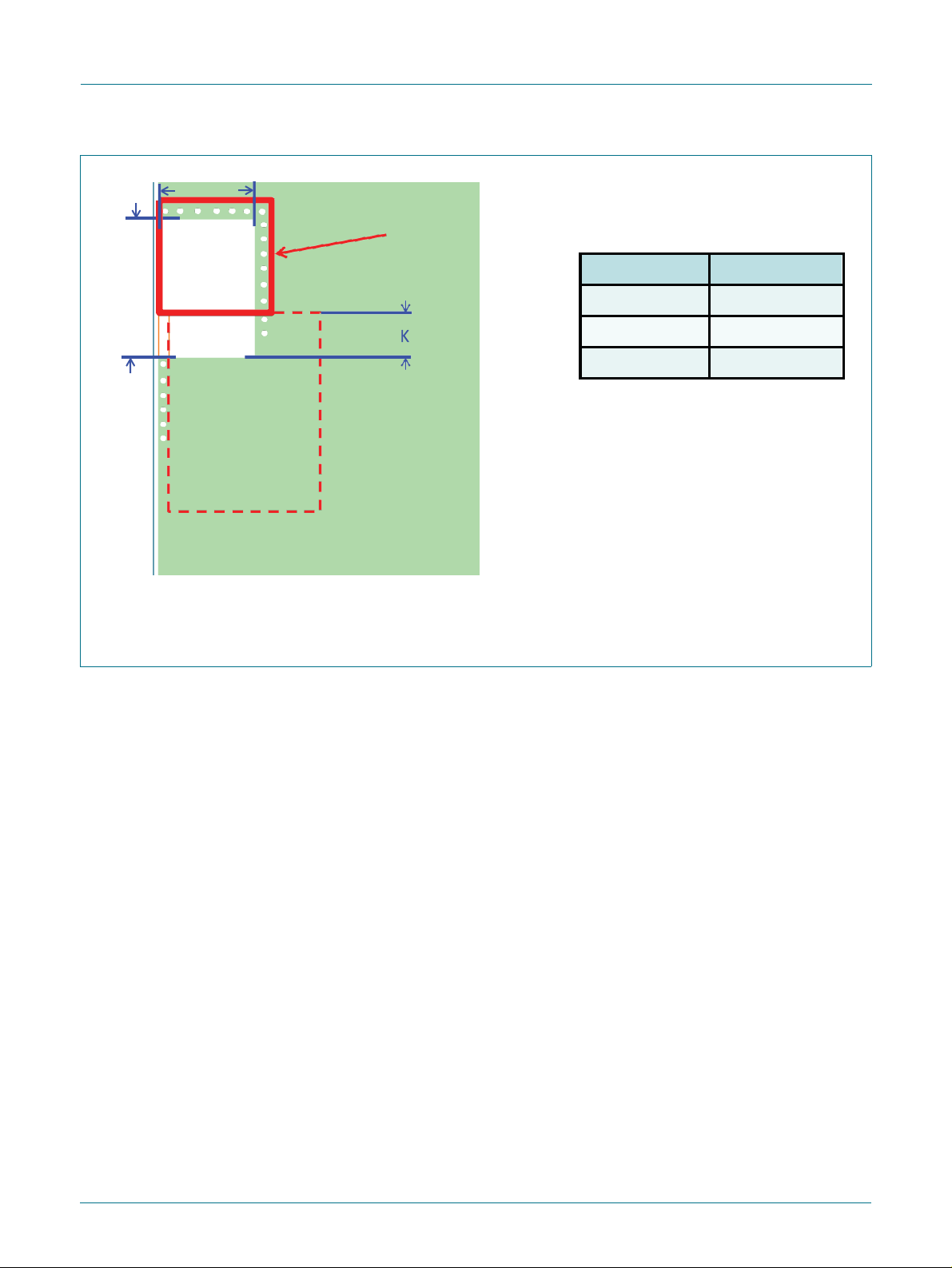
20 of 28
J
Antenna Clearance Area
L
Layer 2,3,4
Fig 11. QN9080-001-M17 SIP on 36 mm
31 mm EVB design guide - center edge - clearance area layers 2, 3, 4
dimensions
Ultra-low power Bluetooth Smart 4.2 SIP
Parameter
Units : mm
J
4.15
K 2 L
5.5
Page 21

QN9080-001-M17
NXP Semiconductors
QN9080-001-M17
User Manual
All information provided in this document is subject to legal disclaimers.
Rev. 0.1 — 08 Dec 2017
© NXP Semiconductors N.V. 2017. All rights reserved.
21 of 28
Ultra-low power Bluetooth Smart 4.2 SIP
10.2.2 CORNER EVB ground plane design
• Do not route signal trace across antenna clearance area
• Connect pin 48 to antenna trace
Antenna Function Pin
9.7mm
6 mm
Fig 12. QN9080-001-M17 SIP on 36 mm 31 mm EVB design guide - corner
Page 22

QN9080-001-M17
NXP Semiconductors
QN9080-001-M17
User Manual
All information provided in this document is subject to legal disclaimers.
Rev. 0.1 — 08 Dec 2017
© NXP Semiconductors N.V. 2017. All rights reserved.
22 of 28
A
L
B
M
E O H F N G J K
Fig 14. QN9080-001-M17 SIP on 36 mm 31 mm EVB design guide - corner - clearance area layer 1
dimensions
Ultra-low power Bluetooth Smart 4.2 SIP
Ant. Trace
3.5mm
Trace
route
Trace
route
Pin48
≥ 31mm
0.25mm
Trace
route
≥ 36mm
Layer 1
Fig 13. QN9080-001-M17 SIP on 36 mm 31 mm EVB design guide - corner - clearance area
Parameter
Units : mm
A
0.5 B 4.34
C
0.5 D 1 E 1.5 F 1.5
G 2 H
2.9
I
3.5 J 0.25 K 0.25
Parameter
Units : mm
L
6.75
M
3.5 N 2 O 2.9
Page 23

QN9080-001-M17
NXP Semiconductors
QN9080-001-M17
User Manual
All information provided in this document is subject to legal disclaimers.
Rev. 0.1 — 08 Dec 2017
© NXP Semiconductors N.V. 2017. All rights reserved.
23 of 28
P
Antenna Clearance Area
S R
Layer 2,3,4
Fig 15. QN9080-001-M17 SIP on 36 mm
31 mm EVB design guide - corner - clearance area layers 2, 3, 4
dimensions
Ultra-low power Bluetooth Smart 4.2 SIP
Parameter
Units : mm
P
6.75
Q 2 R
2.9 S 5.5
10.3. Reflow Profile
For reflow soldering, it is requested to follow the reflow profile in Figure 16 , as well as the
paste manufacturer’s guidelines on peak flow temperature, soak times, time above liquid
and ramp rates.
Fig 16. reflow profile of QN9080-001-M17
Page 24

QN9080-001-M17
NXP Semiconductors
QN9080-001-M17
User Manual
All information provided in this document is subject to legal disclaimers.
Rev. 0.1 — 08 Dec 2017
© NXP Semiconductors N.V. 2017. All rights reserved.
24 of 28
Reflow temperature profile parameters:
T1 : Minimum preheating temperature= 150°C
T2 : Maximum preheating temperature= 180°C
T3 : Soldering temperature= 230°C
T4 : Peak temperature= 260°C
t 1: Preheating duration= (60 – 120) s
t2 : Soldering duration= max. 30s
t3 : Peak temperature duration= max 10s
Table 16. Requested solder reflow profile
Temperature range (°C)
time (s)
Peak temperature: 265°C
10s max
Heating: 230°C or higher
30s max
Preheating: 150°C to 180°C
60s -120s
10.4. Soldering paste and cleaning
NXP does not recommend use of a solder paste that requires the SIP and PCB assembly
to be cleaned (rinsed in water) for the following reasons:
• Solder flux residues and water can be trapped by the PCB, or components and
result in short circuits
NXP recommends use of a 'no clean' solder paste for all its SIP products
Page 25

QN9080-001-M17
NXP Semiconductors
QN9080-001-M17
User Manual
All information provided in this document is subject to legal disclaimers.
Rev. 0.1 — 08 Dec 2017
© NXP Semiconductors N.V. 2017. All rights reserved.
25 of 28
Ultra-low power Bluetooth Smart 4.2 SIP
11.
Package outline
Fig 17. Package outline QN9080-001-M17
Page 26

QN9080-001-M17
NXP Semiconductors
QN9080-001-M17
User Manual
All information provided in this document is subject to legal disclaimers.
Rev. 0.1 — 08 Dec 2017
© NXP Semiconductors N.V. 2017. All rights reserved.
26 of 28
Ultra-low power Bluetooth Smart 4.2 SIP
12.
Abbreviations
Table 17. Abbreviations
Acronym
Description
AHB
Advanced High-performance Bus
APB
Advanced Peripheral Bus
API
Application Programming Interface
DMA
Direct Memory Access
HFRCO
Internal 32 MHz Free-Running Oscillator
HFXO
External 16/32 MHz crystal oscillator
LFRCO
Internal 32 kHz Free-Running Oscillator
LFXO
External 32.768 kHz crystal oscillator
GPIO
General Purpose Input/Output
LSB
Least Significant Bit
MCU
MicroController Unit
SPI
Serial Peripheral Interface
USART
Universal Asynchronous Receiver/Transmitter
TTL
Transistor-Transistor Logic
Page 27

QN9080-001-M17
NXP Semiconductors
QN9080-001-M17
User Manual
All information provided in this document is subject to legal disclaimers.
Rev. 0.1 — 08 Dec 2017
© NXP Semiconductors N.V. 2017. All rights reserved.
27 of 28
Ultra-low power Bluetooth Smart 4.2 SIP
13.
Revision history
Table 18. Revision history
Document ID
Release date
Data sheet status
Change notice
Supersedes
QN9080-001-M17
2018-03-15
Objective data sheet
- - Modifications:
• initial version.
Page 28

QN9080-001-M17
NXP Semiconductors
QN9080-001-M17
User Manual
All information provided in this document is subject to legal disclaimers.
Rev. 0.1 — 08 Dec 2017
© NXP Semiconductors N.V. 2017. All rights reserved.
28 of 28
Ultra-low power Bluetooth Smart 4.2 SIP
14.
Legal information
14.1. Definitions
Draft — The document is a draft version only. The content is still under internal
review and subject to formal approval, which may result in
modifications or additions. NXP Semiconductors does not give any
representations or warranties as to the accuracy or completeness of
information included herein and shall have no liability for the consequences of
use of such information
14.2. Disclaimers
Limited warranty and liability — Information in this document is believed to
be accurate and reliable. However, NXP Semiconductors does not give any
representations or warranties, expressed or implied, as to the accuracy or
completeness of such information and shall have no liability for the
consequences of use of such information. NXP Semiconductors takes no
responsibility for the content in this document if provided by an information
source outside of NXP Semiconductors.
In no event shall NXP Semiconductors be liable for any indirect, incidental,
punitive, special or consequential damages (including - without limitation - lost
profits, lost savings, business interruption, costs related to the removal or
replacement of any products or rework charges) whether or not such
damages are based on tort (including negligence), warranty, breach of
contract or any other legal theory.
Notwithstanding any damages that customer might incur for any reason
whatsoever, NXP Semiconductors’ aggregate and cumulative liability towards
customer for the products described herein shall be limited in accordance
with the Terms and conditions of commercial sale of NXP Semiconductors.
Right to make changes — NXP Semiconductors reserves the right to make
changes to information published in this document, including without
limitation specifications and product descriptions, at any time and without
notice. This document supersedes and replaces all information supplied prior
to the publication hereof.
Suitability for use — NXP Semiconductors products are not designed,
authorized or warranted to be suitable for use in life support, life-critical or
safety-critical systems or equipment, nor in applications where failure or
malfunction of an NXP Semiconductors product can reasonably be
expected to result in personal injury, death or severe property or
environmental damage. NXP Semiconductors and its suppliers accept no
liability for inclusion and/or use of NXP Semiconductors products in such
equipment or applications and therefore such inclusion and/or use is at the
customer’s own risk.
Applications — Applications that are described herein for any of these
products are for illustrative purposes only. NXP Semiconductors makes no
representation or warranty that such applications will be suitable for the
specified use without further testing or modification.
Customers are responsible for the design and operation of their
applications and products using NXP Semiconductors products, and NXP
Semiconductors accepts no liability for any assistance with applications
or customer product design. It is customer’s sole responsibility to
determine whether the NXP Semiconductors product is suitable and fit for
the customer’s applications and products planned, as well as for the
planned application and use of customer’s third party customer(s).
Customers should provide appropriate design and operating safeguards
to minimize the risks associated with their applications and products.
NXP Semiconductors does not accept any liability related to any default,
damage, costs or problem which is based on any weakness or default in
the customer’s applications or products, or the application or use by
customer’s
third party customer(s). Customer is responsible for doing all
necessary testing for the customer’s applications and products using
NXP Semiconductors products in order to avoid a default of the
applications and the products or of the application or use by customer’s
third party customer(s). NXP does not accept any liability in this respect.
Limiting values — Stress above one or more limiting values (as defined in
the Absolute Maximum Ratings System of IEC 60134) will cause permanent
damage to the device. Limiting values are stress ratings only and (proper)
operation of the device at these or any other conditions above those given in
the Recommended operating conditions section (if present) or the
Characteristics sections of this document is not warranted. Constant or
repeated exposure to limiting values will permanently and irreversibly affect
the quality and reliability of the device.
Terms and conditions of commercial sale — NXP Semiconductors
products are sold subject to the general terms and conditions of commercial
sale, as published at http://www.nxp.com/profile/terms, unless otherwise
agreed in a valid written individual agreement. In case an individual
agreement is concluded only the terms and conditions of the respective
agreement shall apply. NXP Semiconductors hereby expressly objects to
applying the customer’s general terms and conditions with regard to the
purchase of NXP Semiconductors products by customer.
No offer to sell or license — Nothing in this document may be interpreted or
construed as an offer to sell products that is open for acceptance or the grant,
conveyance or implication of any license under any copyrights, patents or
other industrial or intellectual property rights.
Export control — This document as well as the item(s) described herein may
be subject to export control regulations. Export might require a prior
authorization from competent authorities.
Non-automotive qualified products — Unless this data sheet expressly
states that this specific NXP Semiconductors product is automotive qualified,
the product is not suitable for automotive use. It is neither qualified nor tested in
accordance with automotive testing or application requirements. NXP
Semiconductors accepts no liability for inclusion and/or use of
non-automotive qualified products in automotive equipment or applications.
In the event that customer uses the product for design-in and use in
automotive applications to automotive specifications and standards, customer
(a) shall use the product without NXP Semiconductors’ warranty of the
product for such automotive applications, use and specifications, and (b)
whenever customer uses the product for automotive applications beyond NXP
Semiconductors’ specifications such use shall be solely at customer’s own risk,
and (c) customer fully indemnifies NXP Semiconductors for any liability,
damages or failed product claims resulting from customer design and use of
the product for automotive applications beyond NXP Semiconductors’
standard warranty and NXP Semiconductors’ product specifications.
Translations — A non-English (translated) version of a document is for
reference only. The English version shall prevail in case of any discrepancy
between the translated and English versions.
14.3 Trademarks
Notice: All referenced brands, product names, service names and trademarks
are the property of their respective owners.
I2C-bus — logo is a trademark of NXP Semiconductors N.V.
Page 29

QN9080-001-M17
NXP Semiconductors
QN9080-001-M17
User Manual
All information provided in this document is subject to legal disclaimers.
Rev. 0.1 — 08 Dec 2017
© NXP Semiconductors N.V. 2017. All rights reserved.
29 of 28
Ultra-low power Bluetooth Smart 4.2 SIP
15.
Contact information
For more information, please visit: http://www.nxp.com
For sales office addresses, please send an email to: salesaddresses@nxp.com
Page 30

QN9080-001-M17
NXP Semiconductors
QN9080-001-M17
User Manual
All information provided in this document is subject to legal disclaimers.
Rev. 0.1 — 08 Dec 2017
© NXP Semiconductors N.V. 2017. All rights reserved.
30 of 28
Ultra-low power Bluetooth Smart 4.2 SIP
16.
Tables
Table 1. Ordering information .......................................... 2
Table 2. Ordering options ................................................. 2
Table 3. Marking code ...................................................... 3
Table 4. Device revision table .......................................... 3
Table 5. Pin description .................................................... 7
Table 6. Termination of unused pins ................................. 9
Table 7. Pin states in different power modes .................... 9
Table 8. General operating conditions .............................. 9
Table 9. Static characteristics: Power consumption in
active modes .................................................... 10
Table 10. Static characteristics: Bluetooth LE power
consumption in active modes ........................... 10
Table 11. Static characteristics: power consumption in
Sleep mode and Power-down mode ................. 10
Table 12. Receiver characteristics .................................... 11
Table 13. Transmitter characteristics ................................ 11
Table 14. BOD static characteristics................................. 12
Table 15. 16-bit ADC characteristics ................................ 12
Table 16. Requested solder reflow profile ......................... 20
Table 17. Abbreviations .................................................... 23
Table 18. Revision history ................................................ 24
17.
Figures
Fig 1. QN9080-001-M17 package marking ...................... 2
Fig 2. QN9080-001-M17 block diagram ........................... 4
Fig 3. QN9080-001-M17 block diagram for customer using
external antenna (Harmonic filter to be in ad equacy
with customer board) ............................................. 5
Fig 4. Pin configuration.................................................... 6
Fig 5. SIP pin out ............................................................. 7
Fig 6. Footprint information for reflow soldering of SIPs 14
Fig 7. QN9080-001-M17 chip antenna / SIP clearance size
(top view) ............................................................. 14
Fig 8. QN9080-001-M17 SIP on 36 mm ´ 31 mm EVB design
guide - center edge .............................................. 15
Fig 9. QN9080-001-M17 SIP on 36 mm ´ 31 mm EVB design
guide - center edge - clearance area 16
Fig 10. QN9080-001-M17 SIP on 36 mm ´ 31 mm EVB
design guide - center edge - clearance area layer 1
dimensions .......................................................... 16
Fig 11. QN9080-001-M17 SIP on 36 mm ´ 31 mm EVB
design guide - center edge - clearance area layers
2, 3, 4 dimensions ............................................... 17
Fig 12. QN9080-001-M17 SIP on 36 mm ´ 31 mm EVB
design guide - corner ........................................... 18
Fig 13. QN9080-001-M17 SIP on 36 mm ´ 31 mm EVB
design guide - corner - clearance area ................ 19
Fig 14. QN9080-001-M17 SIP on 36 mm ´ 31 mm EVB
design guide - corner - clearance area layer 1
dimensions .......................................................... 19
Fig 15. QN9080-001-M17 SIP on 36 mm ´ 31 mm EVB
design guide - corner - clearance area layers 2, 3, 4
dimensions .......................................................... 20
Fig 16. reflow profile of QN9080-001-M17 ....................... 20
Fig 17. Package outline QN9080-001-M17 ...................... 22
Page 31

QN9080-001-M17
NXP Semiconductors
Ultra-low power Bluetooth Smart 4.2 SIP
17.
Contents
1.
General description ............................................................................................................................................. 1
2.
Features and benefits .......................................................................................................................................... 1
3.
Applications ......................................................................................................................................................... 2
4.
Ordering information ........................................................................................................................................... 2
5.
Marking ................................................................................................................................................................ 2
6.
Block diagram ...................................................................................................................................................... 4
7.
Pinning information ............................................................................................................................................. 6
7.1. Pinning ......................................................................................................................................................... 6
7.2. Pin description ............................................................................................................................................. 7
7.2.1 Termination of unused pins ............................................................................................................................ 9
7.2.2 Pin states in different power modes ................................................................................................................. 9
8.
Characteristics ...................................................................................................................................................... 9
8.1. Static characteristics .................................................................................................................................... 9
8.1.1 General operating conditions .......................................................................................................................... 9
8.1.2 Power consumption ..................................................................................................................................... 9
8.2. RF characteristics ....................................................................................................................................... 11
8.2.1 Receiver .................................................................................................................................................... 11
8.2.2 Transmitter ............................................................................................................................................... 11
8.3. Analog characteristics ................................................................................................................................ 12
8.3.1 BOD ......................................................................................................................................................... 12
8.3.2 16-bit ADC characteristics ............................................................................................................................. 12
9.
Compliance statements and documentation .................................................................................................... 13
9.1. FCC Statements and documentation ......................................................................................................... 13
9.1.1
FCC interference Statements .................................................................................................................... 13
9.1.2
FCC end product labelling ......................................................................................................................... 14
9.2. Industry Canada Statement ....................................................................................................................... 15
9.2.1
Industry of Canada end product labelling .................................................................................................... 15
9.3. Japanese Radio Certification Statement .................................................................................................... 15
9.3.1
Radio Certification end product labelling ......................................................................................................... 15
10.
Footprint and PCB placement ........................................................................................................................ 16
10.1. Footprint information for reflow soldering ........................................................................................... 16
10.2. Reference design for EVB ground plane implementation for QN9080-001-M17 ................................. 17
10.2.1 Center edge EVB ground plane design ........................................................................................................ 18
10.2.2 CORNER EVB ground plane design ............................................................................................................. 21
10.3. Reflow Profile ......................................................................................................................................... 23
Page 32

QN9080-001-M17
NXP Semiconductors
10.4. Soldering paste and cleaning ................................................................................................................. 24
11.
Package outline .............................................................................................................................................. 25
12.
Abbreviations ................................................................................................................................................. 26
13.
Revision history .............................................................................................................................................. 27
14.
Legal information ........................................................................................................................................... 28
14.1. Definitions .............................................................................................................................................. 28
14.2. Disclaimers ............................................................................................................................................. 28
14.3 Trademarks ................................................................................................................................................. 28
15.
Contact information ....................................................................................................................................... 29
16.
Tables ............................................................................................................................................................. 30
17.
Figures ............................................................................................................................................................ 30
Please be aware that important notices concerning this document and the product(s)
described herein, have been included in section ‘Legal information’.
© NXP Semiconductors N.V. 2017. All rights reserved.
For more information, please visit: http://www.nxp.com
For sales office addresses, please send an email to: salesaddresses@nxp.com
Date of release: 4 July 2017
Document identifier: QN9080-001-M17
 Loading...