

Page 1
MCUXpresso IDE User Guide
Rev. 11.3.1 — 2 April, 2021 User guide
Page 2

NXP Semiconductors MCUXpresso IDE User Guide
MCUXpresso IDE User Guide -
User Guide
2 April, 2021
Copyright © 2021 NXP Semiconductors
All rights reserved.
All information provided in this document is subject to legal disclaimers
Rev. 11.3.1 — 2 April, 2021
© 2021 NXP Semiconductors. All rights reserved.
ii
Page 3

NXP Semiconductors MCUXpresso IDE User Guide
1. Introduction to MCUXpresso IDE ................................................................................... 1
1.1. MCUXpresso IDE Overview of Features ............................................................. 1
1.1.1. Summary of Features ............................................................................. 2
1.1.2. Supported Debug Probes ........................................................................ 3
1.1.3. Development Boards ............................................................................... 4
2. New Features in MCUXpresso IDE version 11.3.x ......................................................... 7
2.1. Feature Highlights from previous releases of MCUXpresso IDE ............................ 8
3. IDE Overview ............................................................................................................. 12
3.1. Workspaces ..................................................................................................... 12
3.2. Welcome View ................................................................................................. 12
3.3. Documentation and Help .................................................................................. 13
3.4. Perspectives and Views ................................................................................... 14
3.5. Major Components of the Develop Perspective ................................................. 16
3.5.1. Dark Theme .......................................................................................... 18
3.6. The Quickstart Panel ....................................................................................... 19
3.7. Project Explorer and New Projects ................................................................... 21
3.8. Updating MCUXpresso IDE .............................................................................. 22
3.8.1. Locating IDE Components ..................................................................... 23
4. Part Support Overview (Preinstalled and via SDKs) ...................................................... 24
4.1. Preinstalled Part Support ................................................................................. 24
4.1.1. Differences in Preinstalled and SDK Part Handling .................................. 24
4.1.2. Viewing Preinstalled Part Support .......................................................... 25
4.2. SDK Part Support ............................................................................................ 26
4.2.1. Obtaining and Installing a Plugin SDK .................................................... 26
4.2.2. SDK Part Support via SDK Builder ........................................................ 28
4.2.3. Obtaining and Installing an SDK via SDK Builder .................................... 28
4.2.4. Installed SDKs Operations ..................................................................... 30
4.2.5. Installed SDKs Features ........................................................................ 33
4.2.6. Advanced Use: SDK Importing and Configuration ................................... 34
4.2.7. Advanced Use: SDK Misc Options ......................................................... 36
4.2.8. Important notes for SDK Users .............................................................. 37
4.3. Enhanced Project Sharing Features .................................................................. 39
4.3.1. Project Drag and Drop .......................................................................... 39
4.3.2. Project Local SDK Part Support ............................................................. 39
4.3.3. Project Local Support files ..................................................................... 41
5. Creating New Projects using installed SDK Part Support .............................................. 44
5.1. New Project Wizard ......................................................................................... 44
5.1.1. SDK New Project Wizard: Basic Project Creation and Settings ................. 46
5.1.2. SDK New Project Wizard: Advanced Project Settings .............................. 49
5.2. Project Build .................................................................................................... 51
5.2.1. Build Configurations .............................................................................. 52
6. Importing Example Projects (from installed SDKs) ........................................................ 53
6.1. SDK Example Import Wizard ............................................................................ 54
6.1.1. SDK Example Import Wizard: Basic Selection ......................................... 54
6.1.2. SDK Example Import Wizard: Advanced options ..................................... 56
6.1.3. SDK Example Import Wizard: Import from XML fragment ......................... 57
6.1.4. Importing Examples to non default locations ........................................... 59
7. SDK Project Component Management ........................................................................ 60
7.1. SDK Project Component Management example ................................................ 60
7.2. SDK Project Refresh ........................................................................................ 63
8. Creating New Projects using Preinstalled Part Support ................................................. 64
8.1. New Project Wizard ......................................................................................... 64
8.2. Creating a Project ............................................................................................ 65
8.2.1. Selecting the Wizard Type ..................................................................... 66
8.2.2. Configuring the Project .......................................................................... 67
8.2.3. Wizard Options ..................................................................................... 67
8.2.4. Project Created ..................................................................................... 70
9. Importing Example Projects (from the file system) ........................................................ 71
MCUXpresso IDE User Guide -
User Guide
All information provided in this document is subject to legal disclaimers
Rev. 11.3.1 — 2 April, 2021
© 2021 NXP Semiconductors. All rights reserved.
iii
Page 4

NXP Semiconductors MCUXpresso IDE User Guide
9.1. Code Bundles for LPC800 Family Devices ........................................................ 71
9.2. LPCOpen Software Drivers and Examples ........................................................ 72
9.3. Importing an Example Project ........................................................................... 72
9.3.1. Importing Examples for the LPCXpresso4337 Development Board ........... 74
9.4. Exporting Projects ............................................................................................ 75
9.5. Building Projects .............................................................................................. 76
9.5.1. Build Configurations .............................................................................. 76
10. Debug Solutions Overview ........................................................................................ 77
10.1. Starting a Debug Session ............................................................................... 77
10.2. An Introduction to Launch Configuration Files .................................................. 78
10.3. LinkServer Debug Connections ....................................................................... 81
10.4. LinkServer Debug Operation .......................................................................... 81
10.4.1. LinkServer Debug Scripts .................................................................... 83
10.5. LinkServer Troubleshooting ............................................................................ 84
10.5.1. Debug Log .......................................................................................... 84
10.5.2. Flash Programming ............................................................................. 86
10.5.3. LinkServer executables ........................................................................ 87
10.6. PEmicro Debug Connections .......................................................................... 87
10.7. PEmicro Debug Operation .............................................................................. 88
10.7.1. PEmicro Differences from LinkServer Debug ........................................ 88
10.7.2. PEmicro Software Updates .................................................................. 89
10.8. SEGGER Debug Connections ........................................................................ 89
10.8.1. SEGGER software installation .............................................................. 89
10.9. SEGGER Debug Operation ............................................................................ 91
10.9.1. SEGGER Differences from LinkServer Debug ....................................... 91
10.10. SEGGER Troubleshooting ............................................................................ 91
11. Debugging a Project ................................................................................................. 95
11.1. Debugging Overview ...................................................................................... 95
11.1.1. Debug Launch .................................................................................... 95
11.1.2. Debug Probe Selection Dialog (Probes Discovered) .............................. 96
11.1.3. Controlling Execution ........................................................................... 99
11.2. Launch Configurations .................................................................................. 101
11.2.1. Editing a Launch Configuration (LinkServer) ....................................... 103
11.3. Common Debug Operations and Launch Configurations ................................. 104
11.3.1. Debug Quickstart Shortcuts ............................................................... 104
11.3.2. Connecting to a running Target (attach) .............................................. 105
11.3.3. Controlling the initial Breakpoint (on main) .......................................... 107
11.3.4. Debugging Pre-loaded binaries (Add Symbols) ................................... 109
11.3.5. Disconnect Behaviour ........................................................................ 110
11.3.6. Project Flash Programming ................................................................ 111
11.4. Breakpoints .................................................................................................. 112
11.4.1. Breakpoint Types .............................................................................. 112
11.4.2. Breakpoints Resources ...................................................................... 112
11.4.3. Skip All Breakpoints .......................................................................... 113
11.5. Watchpoints ................................................................................................. 113
11.5.1. Using Watchpoints to monitor stack depth .......................................... 115
11.6. Registers ..................................................................................................... 115
11.6.1. Basic Register set (Core Registers) .................................................... 116
11.7. Faults .......................................................................................................... 118
11.8. Peripherals .................................................................................................. 120
11.8.1. Peripheral Filters ............................................................................... 122
11.9. Global and Live Global Variables .................................................................. 123
11.10. Live Global Variable Plotting ....................................................................... 126
11.10.1. Live Global Variable Graphing details ............................................... 127
11.11. Heap and Stack View ................................................................................. 129
11.12. Additional Debug Features .......................................................................... 130
11.12.1. Local Variables ................................................................................ 130
11.12.2. Disassembly view ............................................................................ 131
MCUXpresso IDE User Guide -
User Guide
All information provided in this document is subject to legal disclaimers
Rev. 11.3.1 — 2 April, 2021
© 2021 NXP Semiconductors. All rights reserved.
iv
Page 5
NXP Semiconductors MCUXpresso IDE User Guide
11.12.3. Memory view ................................................................................... 132
12. Configuring a Project .............................................................................................. 133
12.1. Changes available via Quickstart Quick Settings ............................................ 133
12.2. Project Settings ............................................................................................ 134
12.3. Changing the MCU (and associated SDK) ..................................................... 134
12.4. Changing the MCU (SDK) package type ....................................................... 136
13. MCUXpresso Config Tools ...................................................................................... 137
13.1. Using the Config Tools ................................................................................. 137
13.1.1. Tool Perspectives .............................................................................. 138
13.1.2. Pins Tool ..................................................................................... 138
13.1.3. Clocks Tool .................................................................................. 138
13.1.4. Peripherals Tool ........................................................................... 138
13.1.5. Device Configuration Tool ............................................................. 138
13.1.6. TEE Tool ..................................................................................... 139
13.1.7. Generate Code ................................................................................. 139
13.1.8. SDK Components .............................................................................. 139
14. The GUI Flash Tool ................................................................................................ 140
14.1. The Advanced GUI Flash Tool ...................................................................... 141
14.1.1. Advanced GUI Flash Tool command Preview ...................................... 142
14.1.2. Advanced GUI Flash Tool logged Output ............................................ 143
14.1.3. Advanced GUI Flash Tool Programming an arbitrary Binary ................. 144
15. LinkServer Flash Support ........................................................................................ 145
15.1. Default vs Per-Region Flash Drivers ............................................................. 145
15.2. Advanced Flash Drivers ............................................................................... 146
15.2.1. LPC18xx / LPC43xx Internal Flash Drivers .......................................... 146
15.2.2. LPC SPIFI QSPI Flash Drivers ........................................................... 147
15.2.3. i.MX RT QSPI and Hyper Flash Drivers .............................................. 148
15.2.4. Flash Drivers using SFDP (LPC and iMX RT) ..................................... 149
15.3. Kinetis Flash Drivers .................................................................................... 152
15.4. Configuring projects to span multiple Flash Devices ....................................... 153
15.5. The LinkServer GUI Flash Programmer ......................................................... 153
15.6. The LinkServer Command Line Flash Programmer ........................................ 153
15.6.1. Command Line Programming ............................................................. 153
16. C/C++ Library Support ............................................................................................ 160
16.1. Overview of Redlib, Newlib and NewlibNano ................................................. 160
16.1.1. Redlib extensions to C90 ................................................................... 160
16.1.2. Newlib vs NewlibNano ....................................................................... 160
16.2. Library Variants ............................................................................................ 161
16.3. Switching the selected C library .................................................................... 162
16.3.1. Manually Switching ............................................................................ 162
16.4. What is Semihosting? ................................................................................... 163
16.4.1. Background to Semihosting ............................................................... 163
16.4.2. Semihosting Implementation .............................................................. 163
16.4.3. Semihosting Performance .................................................................. 163
16.4.4. Important notes about using Semihosting ........................................... 163
16.4.5. Semihosted printf and Debugging ....................................................... 164
16.4.6. Semihosting Specification .................................................................. 165
16.5. Use of printf ................................................................................................. 165
16.5.1. Redlib printf Variants ......................................................................... 165
16.5.2. NewlibNano printf Variants ................................................................. 165
16.5.3. Newlib printf variants ......................................................................... 166
16.5.4. Printf when using LPCOpen ............................................................... 166
16.5.5. Printf when using SDK ...................................................................... 166
16.5.6. Retargeting printf/scanf ...................................................................... 166
16.5.7. How to use ITM Printf ....................................................................... 167
16.6. itoa() and uitoa() .......................................................................................... 168
MCUXpresso IDE User Guide -
User Guide
All information provided in this document is subject to legal disclaimers
Rev. 11.3.1 — 2 April, 2021
© 2021 NXP Semiconductors. All rights reserved.
v
Page 6

NXP Semiconductors MCUXpresso IDE User Guide
16.6.1. Redlib ............................................................................................... 168
16.6.2. Newlib/NewlibNano ............................................................................ 169
16.7. Libraries and linker scripts ............................................................................ 169
17. Memory Configuration and Linker Scripts ................................................................. 171
17.1. Introduction .................................................................................................. 171
17.2. Managed Linker Script Overview ................................................................... 171
17.3. How are Managed Linker Scripts Generated? ................................................ 172
17.4. Default Image Layout ................................................................................... 173
17.5. Examining the layout of the generated image ................................................ 173
17.5.1. Linker --print-memory-usage .............................................................. 174
17.5.2. arm-none-eabi-size ............................................................................ 175
17.5.3. Linker Map Files ............................................................................... 175
17.6. Image Information (Info) ............................................................................... 175
17.6.1. Memory Usage .................................................................................. 177
17.6.2. Memory Contents .............................................................................. 177
17.6.3. Call Graph ........................................................................................ 178
17.6.4. Use of Filters .................................................................................... 180
17.7. Enhanced Syntax Highlighting ...................................................................... 181
17.8. Other Options affecting the Generated Image ................................................ 187
17.8.1. LPC MCUs – Code Read Protection ................................................... 187
17.8.2. Kinetis MCUs – Flash Config Blocks .................................................. 188
17.8.3. Placement of USB Data ..................................................................... 189
17.8.4. Plain Load Image .............................................................................. 189
17.8.5. Link Application to RAM .................................................................... 190
17.9. Modifying the Generated Linker Script / Memory Layout ................................. 191
17.10. Using the Memory Configuration Editor ....................................................... 191
17.10.1. Editing a Memory Configuration ....................................................... 192
17.10.2. Device specific vs Default Flash Drivers ........................................... 195
17.10.3. Restoring a Memory Configuration ................................................... 195
17.10.4. Copying Memory Configurations ....................................................... 195
17.11. Global Data Placement ............................................................................... 195
17.12. Modifying heap/stack placement ................................................................. 196
17.12.1. MCUXpresso style Heap and Stack .................................................. 196
17.12.2. LPCXpresso style Heap and Stack ................................................... 197
17.12.3. Reserving RAM for IAP Flash Programming ...................................... 198
17.12.4. Stack Checking ............................................................................... 198
17.12.5. Heap Checking ................................................................................ 199
17.12.6. Checking the Heap from your Application ......................................... 199
17.13. Placement of specific code/data Items ......................................................... 200
17.13.1. Placing code and data into different Memory Regions ........................ 200
17.13.2. Placing data into different RAM blocks using Macros ......................... 202
17.13.3. Noinit Memory Sections ................................................................... 202
17.13.4. Placing code/rodata into different FLASH Blocks ............................... 203
17.13.5. Placing specific functions into RAM Blocks ........................................ 204
17.13.6. Reducing Code Size when support for LPC CRP or Kinetis Flash
Config Block is Enabled ................................................................................ 205
17.14. FreeMarker Linker Script Templates ............................................................ 205
17.14.1. Basics ............................................................................................. 206
17.14.2. Reference ....................................................................................... 206
17.15. FreeMarker Linker Script Template Examples .............................................. 211
17.15.1. Relocating code from FLASH to RAM ............................................... 211
17.15.2. Configuring projects to span multiple Flash Devices ........................... 214
17.16. Disabling Managed Linker Scripts ............................................................... 215
18. Multicore Projects ................................................................................................... 216
18.1. Introduction .................................................................................................. 216
18.2. Creating a Master / Slave project Pair (using an SDK) .................................... 217
18.2.1. Creating the M0 Slave project ............................................................ 217
18.2.2. Creating the M4 Master project .......................................................... 219
MCUXpresso IDE User Guide -
User Guide
All information provided in this document is subject to legal disclaimers
Rev. 11.3.1 — 2 April, 2021
© 2021 NXP Semiconductors. All rights reserved.
vi
Page 7

NXP Semiconductors MCUXpresso IDE User Guide
18.3. Creating a Master / Slave project Pair (using Preinstalled Part Support) ........... 223
18.3.1. Creating the M0 Slave project ............................................................ 223
18.3.2. Creating the M4 Master project .......................................................... 225
18.4. Debugging MultiCore Projects ....................................................................... 226
18.4.1. Controlling Debug Views .................................................................... 227
18.4.2. Slave Project Debug .......................................................................... 228
18.4.3. Auto-debug slave project(s) for multicore projects ................................ 229
18.5. MultiCore Projects additional Information ....................................................... 231
18.5.1. Defines ............................................................................................. 231
18.5.2. Slave Boot Code ............................................................................... 231
18.5.3. Reset Handler code ........................................................................... 231
19. Appendix – Additional Hints and Tips ....................................................................... 232
19.1. Part Support Handling from SDKs ................................................................. 232
19.1.1. SDK Version control .......................................................................... 232
19.1.2. SDK Manifest versioning .................................................................... 232
19.1.3. Device versions ................................................................................. 233
19.2. How do I switch between Debug and Release builds? .................................... 234
19.2.1. Changing the build configuration of a single project ............................. 234
19.2.2. Changing the build configuration of multiple projects ............................ 234
19.3. Editing Hints and Tips .................................................................................. 234
19.3.1. Multiple views onto the same file ........................................................ 234
19.3.2. Viewing two edited files at once ......................................................... 235
19.3.3. Source folding ................................................................................... 235
19.3.4. Editor templates and Code completion ............................................... 235
19.3.5. Brace matching ................................................................................. 235
19.3.6. Syntax coloring ................................................................................. 235
19.3.7. Comment/uncomment block ............................................................... 236
19.3.8. Format code ...................................................................................... 236
19.3.9. Correct Indentation ............................................................................ 236
19.3.10. Insert spaces for tabs in editor ......................................................... 236
19.3.11. Replacing tabs with spaces .............................................................. 236
19.4. Hardware Floating Point Support .................................................................. 237
19.4.1. Floating Point Variants ....................................................................... 237
19.4.2. Floating point use – Preinstalled MCUs .............................................. 237
19.4.3. Floating point use – SDK installed MCUs ........................................... 238
19.4.4. Modifying floating point configuration for an existing project .................. 238
19.4.5. Do all Cortex-M4 MCUs provide floating point in hardware? ................. 238
19.4.6. Why do I get a hard fault when my code executes a floating point
operation? .................................................................................................... 238
19.5. LinkServer Scripts ........................................................................................ 239
19.5.1. Supplied Scripts ................................................................................ 239
19.5.2. User Scripts ...................................................................................... 239
19.5.3. Debugging code from RAM ................................................................ 239
19.5.4. LinkServer Scripting Features ............................................................ 240
19.6. RAM projects with LinkServer ....................................................................... 243
19.6.1. Advantages of developing with RAM projects ...................................... 244
19.7. The Console View ........................................................................................ 244
19.7.1. Console types ................................................................................... 245
19.7.2. Copying the contents of a console ..................................................... 245
19.7.3. Relocating and duplicating the Console view ....................................... 246
19.8. Using Terminal View for UART communication with target .............................. 247
19.9. Using and troubleshooting LPC-Link2 ............................................................ 250
19.9.1. LPC-Link2 hardware .......................................................................... 250
19.9.2. Softloaded vs Pre-programmed probe firmware ................................... 250
19.9.3. LPC-Link2 firmware variants .............................................................. 250
19.9.4. Manually booting LPC-Link2 .............................................................. 251
19.9.5. LPC-Link2 windows drivers ................................................................ 253
19.9.6. LPC-Link2 failing to enumerate .......................................................... 253
MCUXpresso IDE User Guide -
User Guide
All information provided in this document is subject to legal disclaimers
Rev. 11.3.1 — 2 April, 2021
© 2021 NXP Semiconductors. All rights reserved.
vii
Page 8

NXP Semiconductors MCUXpresso IDE User Guide
19.9.7. Troubleshooting LPC-Link2 ................................................................ 255
19.10. Using and troubleshooting MCU-Link .......................................................... 255
19.10.1. MCU-Link hardware ......................................................................... 255
19.10.2. MCU-Link firmware .......................................................................... 256
19.10.3. MCU-Link Windows Drivers .............................................................. 257
19.10.4. Troubleshooting MCU-Link ............................................................... 257
19.11. Creating bin, hex or S-Record files .............................................................. 258
19.11.1. Simple conversion within the IDE ..................................................... 258
19.11.2. From the command line ................................................................... 259
19.11.3. Automatically converting the file during a build .................................. 259
19.11.4. Binary files and checksums .............................................................. 259
19.12. Post-build (and Pre-build) steps .................................................................. 259
19.12.1. Temporarily removing post-build steps .............................................. 260
19.13. Save Info for Support ................................................................................. 260
MCUXpresso IDE User Guide -
User Guide
All information provided in this document is subject to legal disclaimers
Rev. 11.3.1 — 2 April, 2021
© 2021 NXP Semiconductors. All rights reserved.
viii
Page 9

NXP Semiconductors MCUXpresso IDE User Guide
1. Introduction to MCUXpresso IDE
MCUXpresso IDE version 11.3.1 is a low-cost microcontroller (MCU) development platform
ecosystem from NXP. It provides an end-to-end solution enabling engineers to develop
embedded applications from initial evaluation to final production.
The MCUXpresso platform ecosystem includes:
• MCUXpresso IDE [12] - a software development environment for creating applications for
NXP’s ARM Cortex-M based MCUs including “LPC”, “Kinetis” and iMX RT" ranges.
• MCUXpresso Config Tools [137] , comprising of Pins, Clocks and Peripherals Tools that are
designed to work with SDK projects and are fully integrated and installed by default.
• MCUXpresso SDKs [24], each offering a package of device support and example software
extending the capability and part knowledge of MCUXpresso IDE.
• The range of LPCXpresso development boards, each of which includes a built-in “LPCLink”, “LPC-Link2”, or CMSIS-DAP compatible debug probe. These boards are developed in
collaboration with Embedded Artists.
• The range of Tower and Freedom development boards, most of which include an OpenSDA
debug circuit supporting a range of firmware options.
• The range of iMX RT Series EVK development board which include an OpenSDA debug circuit
supporting a range of firmware options, or high performance FreeLink (LPC-Link2 compatible)
debug probe.
• The standalone “LPC-Link2” debug probe.
• The standalone “MCU-Link” debug probe.
This guide is intended as an introduction to using MCUXpresso IDE. It assumes that you have
some knowledge of MCUs and software development for embedded systems.
Note: MCUXpresso IDE incorporates technology and design from LPCXpresso IDE. This means
that users familiar with LPCXpresso IDE will find MCUXpresso IDE looks relatively familiar.
1.1 MCUXpresso IDE Overview of Features
MCUXpresso IDE is a fully featured software development environment for NXP’s ARMbased MCUs, and includes all the tools necessary to develop high-quality embedded software
applications in a timely and cost effective fashion.
MCUXpresso IDE is based on the Eclipse IDE and includes the industry standard ARM GNU
toolchain. It brings developers an easy-to-use and unlimited code size development environment
for NXP MCUs based on Cortex-M cores (LPC, Kinetis and iMX RT). The IDE combines the
best of the widely popular LPCXpresso and Kinetis Design Studio IDE’s, providing a common
platform for all NXP Cortex-M microcontrollers.
MCUXpresso IDE is a free toolchain providing developers with no restrictions on code or
debug sizes. It provides an intuitive and powerful interface with profiling, power measurement
on supported boards, GNU tool integration and library, multicore capable debugger, trace
functionality and more. MCUXpresso IDE debug connections support Freedom, Tower, EVK,
LPCXpresso and custom development boards with industry leading open-source and commercial
debug probes including MCU-Link, LPC-Link2, PEmicro and SEGGER.
MCUXpresso IDE User Guide -
User Guide
The fully featured debugger supports both SWD and JTAG debugging, and features direct
download to on-chip and external flash memory.
For the latest details on new features and functionality, please visit:
http://www.nxp.com/mcuxpresso/ide
All information provided in this document is subject to legal disclaimers
© 2021 NXP Semiconductors. All rights reserved.
Rev. 11.3.1 — 2 April, 2021
1
Page 10

NXP Semiconductors MCUXpresso IDE User Guide
1.1.1 Summary of Features
Complete C/C++ integrated development environment
• Eclipse-based IDE with many ease-of-use enhancements
• Built on Eclipse 2020.06 (Eclipse Platform 4.16.0 and CDT 9.11.1)
• The IDE installs with various Eclipse plugins including:
• Git, and support for PEmicro debug probes
• The IDE can be further enhanced with many other Eclipse plugins
• Command line tools are included for integration into build, test, and manufacturing systems
Industry standard GNU toolchain GCC9-2020-q2-update including:
• C and C++ compilers, assembler, and linker
• Converters for SREC, HEX, and binary
Advanced project wizards
• Simple creation of pre-configured applications for specific MCUs [64]
• Extendable with MCUXpresso SDKs [44]
• Device-specific support for NXP’s ARM-based MCUs (including LPC, Kinetis and iMX RT)
• Automatic generation [171] of linker scripts for correct placement of code and data into Flash
and RAM
• Extended support for flexible placement of heap and stack [196]
• Automatic generation of MCU-specific startup and device initialization code
• Note: No assembler required with Cortex-M MCUs
Advanced multicore support
• Provision for creating linked projects [216] for each core in multicore MCUs
• Debugging of multicore projects [226] within a single IDE instance, with the ability to link
various debug views to specific cores
Fully featured native debugger supporting SWD and JTAG connection via LinkServer
• Built-in optimized Flash programming [145] for internal and external QSPI and Hyper Flash
• High-level and instruction-level debug [99]
• Breakpoints [112] and Watchpoints [113]
• Views of CPU registers [115] and on-chip peripherals [120]
• Support for multiple devices on the JTAG scan-chain
Full install and integration of 3rd party debug solutions from:
• PEmicro [87]
• SEGGER J-Link [89]
Library support
• Redlib: a small-footprint embedded C library
• RedLib-nf: a smaller footprint library offering reduced fprintf support
• RedLib-mb: a library variant offering enhanced semihosting performance
• Newlib: a complete C and C++ library
• NewlibNano: a new small-footprint C and C++ library, based on Newlib
• LPCOpen MCU software libraries
• Cortex Microcontroller Software Interface Standard (CMSIS) libraries and source code
• Extendible support per device via MCUXpresso SDKs
MCUXpresso IDE User Guide -
User Guide
Trace functionality
• Instruction trace via Embedded Trace Buffer (ETB) on certain Cortex-M3/M4/M7 based MCUs
or via Micro Trace Buffer (MTB) on Cortex-M0+ based MCUs
All information provided in this document is subject to legal disclaimers
© 2021 NXP Semiconductors. All rights reserved.
Rev. 11.3.1 — 2 April, 2021
2
Page 11

NXP Semiconductors MCUXpresso IDE User Guide
• Providing a snapshot of application execution with linkage back to source, disassembly and
profile
• SWO Trace on Cortex-M3/M4/M7/M33 based MCUs when debugging via MCU-Link and LPCLink2, providing functionality including:
• Profile tracing
• Interrupt tracing
• Datawatch tracing
• Printf over ITM
• Note: Now extended to work with PEmicro and SEGGER J-Link, in addition to native
LinkServer
LinkServer Energy Measurement
• On LPCXpresso boards, sample power usage at adjustable rates of up to 100 ksps; average
power and energy usage display option
• Explore detailed plots of collected data in the IDE
• Export and import data for offline analysis
MCUXpresso Configuration Tools
• MCUXpresso Config Tools [137], designed to work with SDK projects are fully integrated
and installed by default
1.1.2 Supported Debug Probes
MCUXpresso IDE installs with built in support for 3 debug solutions. This support includes the
installation of all necessary drivers and supporting software.
Note: Certain mbed boards require a serial port driver to be recognised and this one exception
must be installed separately for each board. The driver is linked from Help -> Additional
Resources -> MBED Serial Port Driver Website
In normal use MCUXpresso IDE presents a similar interface and array of features for each of
the solutions listed below:
Native LinkServer (including CMSIS-DAP) as also used in LPCXpresso IDE
• this supports a variety of debug probes including OpenSDA programmed with CMSIS-DAP
firmware, LPC-Link2 etc.
• https://community.nxp.com/message/630896
PEmicro
• this supports a variety of debug probes including OpenSDA programmed with PEmicro
compatible firmware and MultiLink and Cyclone probes
• https://www.pemicro.com/
SEGGER J-Link
• this supports a variety of debug probes including OpenSDA programmed with J-Link
compatible firmware and J-Link debug probes
• https://www.segger.com/
MCUXpresso IDE User Guide -
User Guide
Please see Debug Solutions Overview Chapter [77] for more details.
Note: Kinetis Freedom and Tower boards typically provide an on-board OpenSDA debug circuit.
This can be programmed with a range of debug firmware including:
• mBed CMSIS-DAP – supported by LinkServer connections
• DAP-Link – supported by LinkServer connections (DAP-Link is preferred to mBed CMSIS-DAP
when available)
All information provided in this document is subject to legal disclaimers
© 2021 NXP Semiconductors. All rights reserved.
Rev. 11.3.1 — 2 April, 2021
3
Page 12
NXP Semiconductors MCUXpresso IDE User Guide
• J-Link – supported by SEGGER J-Link connections
• PEmicro – supported by PEmicro connections
The default firmware can be changed if required, for details of the procedure and range of
supported firmware options please information visit: http://www.nxp.com/opensda
Tip
Under Windows 10, OpenSDA Bootloaders might experience problems and the
OpenSDA LED will blink an error code. The following article discusses the problem
and how it can be fixed: https://mcuoneclipse.com/2018/04/10/recovering-opensda-
boards-with-windows-10
1.1.3 Development Boards
NXP have a large range of development boards that work seamlessly with MCUXpresso IDE
including:
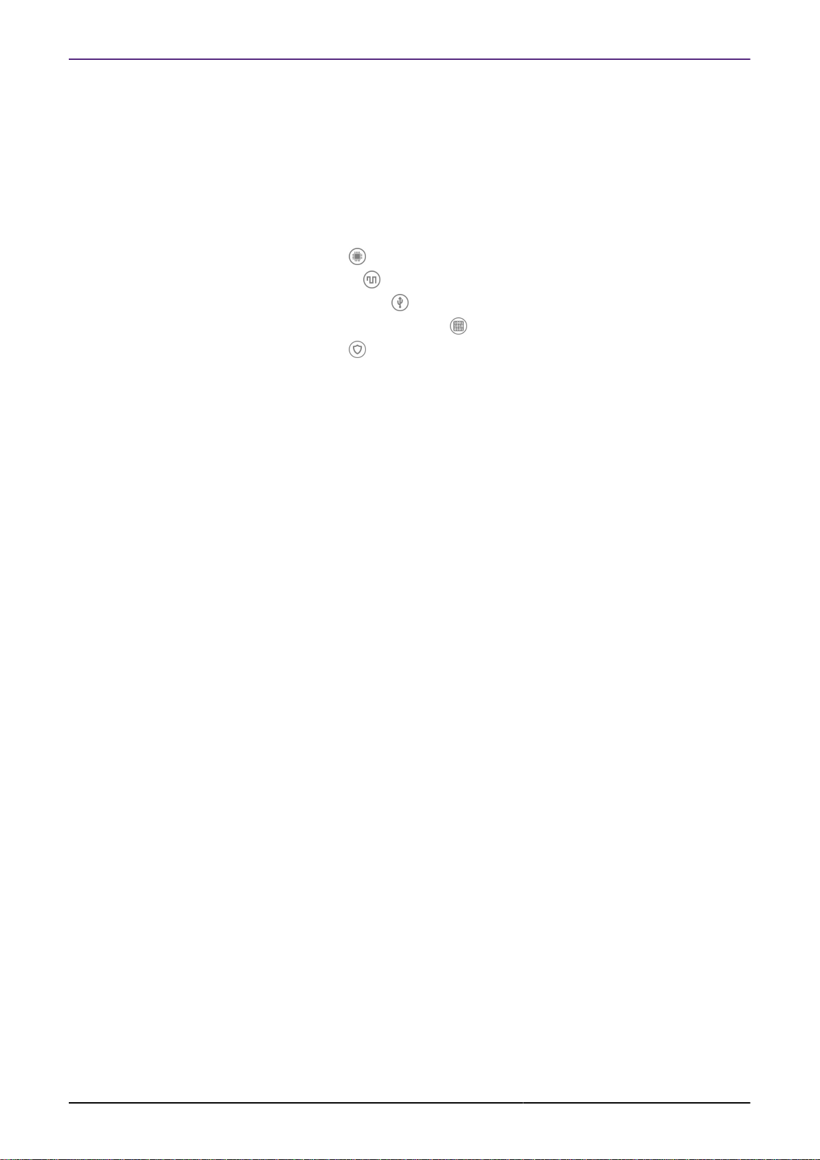
LPCXpresso Boards for LPC
These boards provide practical and easy-to-use development hardware to use as a starting point
for your LPC Cortex-M MCU based projects.
Figure 1.1. LPC800 series (LPCXpresso802)
Figure 1.2. LPCXpresso Development Board (LPCXpresso54608)
MCUXpresso IDE User Guide -
User Guide
For more information, visit: http://www.nxp.com/lpcxpresso-boards
All information provided in this document is subject to legal disclaimers
Rev. 11.3.1 — 2 April, 2021
© 2021 NXP Semiconductors. All rights reserved.
4
Page 13
NXP Semiconductors MCUXpresso IDE User Guide
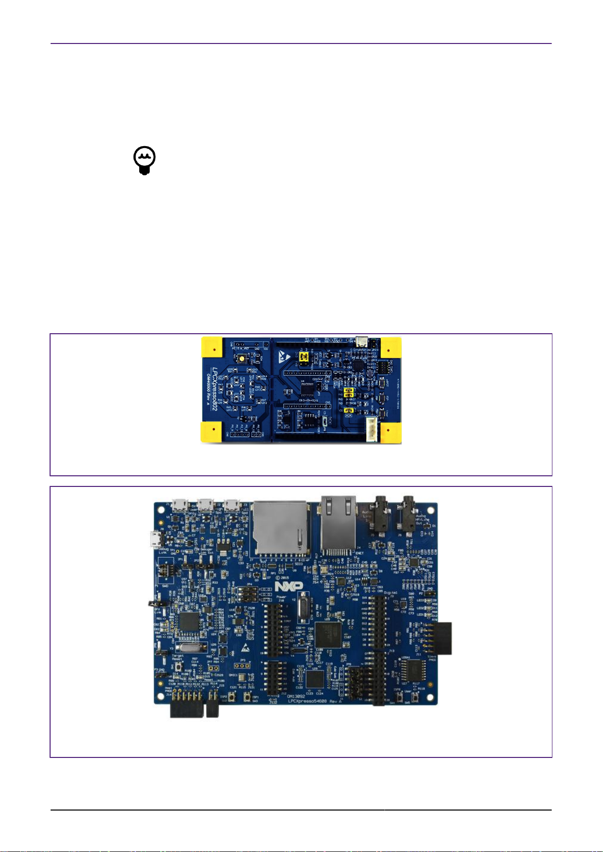
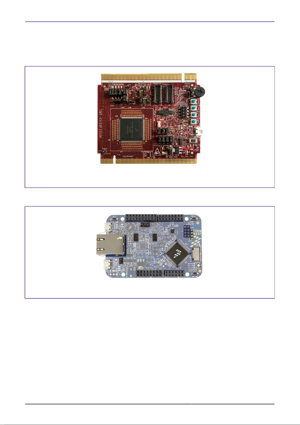
Freedom and Tower Boards for Kinetis
Similarly, for Kinetis MCUs there are many development boards available including the popular
Freedom and Tower ranges of boards.
Figure 1.3. Tower (TWR-KV58F220M)
For more information, visit: http://www.nxp.com/pages/:TOWER_HOME
Figure 1.4. Freedom (FRDM-K64F)
For more information, visit: http://www.nxp.com/pages/:FREDEVPLA
iMX RT Crossover Processor Boards
MCUXpresso IDE User Guide -
User Guide
iMX RT based boards bring the convergence of low power applications processors with highperformance microcontrollers.
All information provided in this document is subject to legal disclaimers
© 2021 NXP Semiconductors. All rights reserved.
Rev. 11.3.1 — 2 April, 2021
5
Page 14
NXP Semiconductors MCUXpresso IDE User Guide
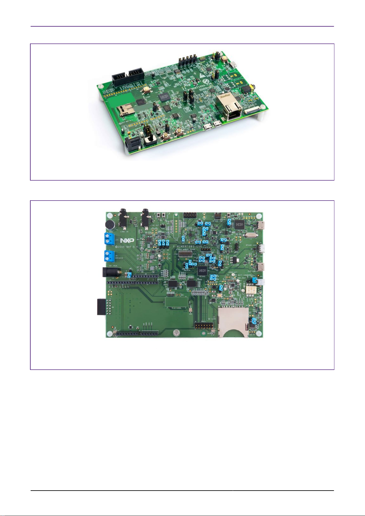
Figure 1.5. i.MX RTxxxx Series (MIMXRT1050-EVK)
For more information, visit: https://www.nxp.com/pages/:IMX-RT-SERIES
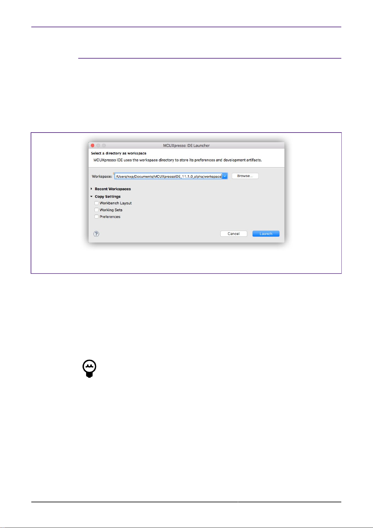
Figure 1.6. i.MX RTxxx Series (MIMXRT600-EVK)
For more information, visit: https://www.nxp.com/pages/:IMX-RT-SERIES
MCUXpresso IDE User Guide -
User Guide
All information provided in this document is subject to legal disclaimers
Rev. 11.3.1 — 2 April, 2021
© 2021 NXP Semiconductors. All rights reserved.
6
Page 15

NXP Semiconductors MCUXpresso IDE User Guide
2. New Features in MCUXpresso IDE version 11.3.x
The new MCUXpresso IDE product comes with a set of improvements and bug fixes including:
Product
• Eclipse version to 2020.06 (Eclipse Platform 4.16.0 / CDT9.11.1).
• MCUXpresso IDE integrated with OpenJDK8
• GNU ARM Embedded Toolchain to GCC9-2020-q2-update.
• Upgraded SEGGER J-Link software (v6.98a).
• Upgraded PEmicro plugin (v4.9.1).
• Upgraded MCUXpresso Config Tools (v9).
• Integrated GNU test coverage (gcov) and performance analysis (gprof) tools and Eclipse
plugins.
• Added i.MX RT1024 support.
• Added i.MX RT1170 B0 support.
• Added i.MX RT1160 support.
• Added RT500 B2 support.
• Added LPC55S06 support.
• Added K32W041AM/K32W041A support.
• Added K32W061 support.
• Added 88MW320 support.
• Added MCU-Link probe debug support.
IDE
• Added Energy Measurement view aiming to replace the Power Measurement view. Main
capabilities:
• The new view comes with the same feature-set as the old Power Measurement view;
• From a GUI perspective, it offers consistent look & feel with other views that display and
controls graphs (e.g. Global Variables, SWO-related views);
• Compatible with older LPCs having power on board measurement circuits;
• Power and energy estimation capability;
• Multiprobe and multiview support;
• Data collecting during an out-of-debug session and also during an active debug session;
• Data collecting with an active debug session while the core is in debug mode. Behavior is
controlled via toolbar buttons;
• Configuration of the server-side (rltool) and of the IDE using the Config tab within the view;
• Import/Export data functionality for offline analysis;
• See MCUXpresso_IDE_Energy_Measurement.pdf (or Help -> Help Contents) for details.
• Community forum accessible now from the main toolbar too (together with the older link from
Help -> MCUXpresso IDE support forum). The default selection will open the community
web inside the IDE.
• If you want to set the default browser as external browser, use Window -> Preferences ->
General -> Web browser -> Use external web browser.
• Enhanced SWO views:
• SWO Config: added new Tab for data traffic statistics, configuration for ITM Stimulus ports;
• SWO Profile: added samples and details tabs;
• SWO Data: added plot (similar to Global Variables);
• SWO Stats: moved inside SWO Config;
• ITM Console: added one tab for each stimulus port;
MCUXpresso IDE User Guide -
User Guide
Debug
• Auto-debug slave project(s) for multicore projects option becomes default option for multicore
debug purpose (for LinkServer debug connection only). That means, in the case of multicore
All information provided in this document is subject to legal disclaimers
© 2021 NXP Semiconductors. All rights reserved.
Rev. 11.3.1 — 2 April, 2021
7
Page 16

NXP Semiconductors MCUXpresso IDE User Guide
projects on which master project refers one or several slave projects, debug sessions will be
automatically started for slave projects after initiating debug with the master project.
• Option is set by default on: Window -> Preferences -> MCUXpresso IDE -> Debug
Options -> LinkServer Options -> Miscellaneous -> Enable Auto-debug slave
project(s) for multicore projects.
• If you don’t want to have this feature enabled (so if you want to start debug sessions for
each core independently), uncheck this option.
• Similar, Auto-debug slave project(s) for multicore projects option becomes default option for
multicore debug purpose for PEmicro too. Option is set by default on: Window -> Preferences
-> MCUXpresso IDE -> Debug Options -> PEMicro Options -> Enable Auto-debug slave
project(s) for multicore projects.
• Firmware version check on MCU-Link probes [98].
Automation/Command line
• Added SDK command line documentation within the layout (
MCUXpresso_SDK_Command_Line_User_Guide.pdf)
• Extend CLI functionality – Add new command to list SDK info:
• -filter=string : filters the available information based on regex expression string.
• e.g. -filter=K64 will display all data containing K64 string.
Please also see the supplied ReadMe document for further information and details of bug fixes
etc. This document is located within the MCUXpresso IDE installation folder.
2.1 Feature Highlights from previous releases of MCUXpresso IDE
Product
• GNU make 4.2.1 is now integrated on IDE on all OS-es.
• FreeRTOS TAD synchronization with FreeRTOS 202002.00.
• New Welcome View [12], designed to provide a dramatically improved out-of-box
experience for new users
• Improved IDE Update [22] capability simplifying the update procedure for all supported
hosts
• Scripts to create a command line environment now supplied in DOS and Bash versions
• Use of these scripts is described within the Installation Guide
• SDK installation options improved, see SDK Importing and Configuration [34]
• Windows version now uses Busybox (from the GNU MCU Eclipse Windows Build Tools project)
to provide Unix-like layer for GCC tools
• All previous Pro Edition features have been incorporated into the standard Free edition and
the Pro edition has been discontinued
IDE
• Expressions added in Global Variables are now persistent between debug sessions.
• Added new control to manage the maximum number of child expressions that are evaluated
in advance by the Live Variables service. This improves the Global Variables window
responsiveness for instance when large structures are displayed. New control available on
Eclipse Preferences -> MCUXpresso IDE -> Debug Options -> “Number of subexpressions
proactively evaluated by Live Variables service”. Default is 2 set as depth.
• Added Save Info for Support [260] option to help reporting an issue by gathering MCU IDE
environment information.
• New Plugin SDK [26] mechanism that provides a simpler flow for selection and installation
of MCUXpresso IDE SDKs
• New Dark Theme [18] provides a low-light interface that displays mostly dark surfaces that
may be more relaxing on the eye
• Improved Image Information View [175]
MCUXpresso IDE User Guide -
User Guide
All information provided in this document is subject to legal disclaimers
Rev. 11.3.1 — 2 April, 2021
© 2021 NXP Semiconductors. All rights reserved.
8
Page 17

NXP Semiconductors MCUXpresso IDE User Guide
• Improved Installed SDK Operations [30]
• Improved Code Size [174]
• the code size of debug builds of SDK projects has been reduced by decreasing the overhead
of the assert() function, which is commonly called by SDK functions.
• Added support for handling more complex specification of dependencies between SDK
components.
• Heap and Stack View [129] for all debug solutions
• shows usage against allocated Managed Linkerscript [171] RAM allocation for bare metal
projects
• Live Heap updates and stack when paused
• Image Information View [175] extends and replaces the Symbol Browser
• incorporating detailed memory usage plus hyperlinked Memory Content and Static Call
Graph display
• Revamped Develop Perspective [16]
• Editor Syntax Highlighting [181] for linker scripts, linker templates and debug map files
• providing linked navigation of file contents
• Redesigned Quickstart Panel [16]
• Quick Start panel -> Quick Settings [133] now displays the current settings for Library
• links for Dedicated Debug Operations [104] for all supported Debug Solutions
• Faults View [118] automatically displayed (for LinkServer) should a CPU fault occur
• Improved Registers View [115] with enhanced display and grouping options
• Launch Configurations [78] are now only automatically generated for the selected build
configuration
• Project Memory Configuration [192] can now be edited in place for settings and wizards
• Project Explorer view enhanced to display current project build configuration for the selected
project (also displayed in Quickstart view)
• Support for new MCUs based on the ARM Cortex M33
Projects
• Imported or new projects [21] will now expand to show the source file containing the main
function and also opens this file within the editor
• Improved display of Components in New Project Wizard [44]
• Quick Start panel -> Quick Settings [133] now displays the current settings
• Project association with an SDK (MCU) can now be flexibly managed, maintaining existing
memory configuration if desired see Project Configuration [133]
• Many enhancements for improved Project Sharing [39] including:
• Drag and Drop of projects for import and export
• Options for project local inclusion of: SDK part support, flash drivers, and LinkServer connect
and reset scripts
• Project Virtual Nodes [134] introduced to enable easy visibility and editing of project
configurations
• Project GUI Flash Tool [111] for all debug solutions delivered via project launch
configurations
Debug
• Most LinkServer Flash Programming [86] now implements a Verify Same operation for any
flash sector that are unchanged from previous debug operations
• LinkServer MultiCore debug operations can now be started via a single click
• Reworked Live Global Variables [123] graphing offering improvements to variable selection
and display
• Reworked SWO Interrupt trace
• LinkServer LPC-Link2 firmware now softloaded as v5.361 which offers improved debug control
through target reset
MCUXpresso IDE User Guide -
User Guide
All information provided in this document is subject to legal disclaimers
Rev. 11.3.1 — 2 April, 2021
© 2021 NXP Semiconductors. All rights reserved.
9
Page 18

NXP Semiconductors MCUXpresso IDE User Guide
• Redesigned LinkServer Launch configuration [78] dialogue offering improved functionality
and ease of use
• this is reflected in a new LinkServer Launch configuration icon
• New launch configuration tab for all debug solutions to allow the loading of Debug
Symbols [109] from additional images
• Improved performance for Single Stepping LinkServer debug connections
• Implemented support for SWO Trace on Cortex-M33 based MCUs
• Live Global Variables [123] are now available for SEGGER JLINK and PEmicro debug
probes in addition to LinkServer LPC-Link2
• LinkServer internal flash drivers prioritised over supplied SDK drivers
• Debug Shortcut buttons [104] now Multicore aware ensuring slave project attach settings
are observed
• Improved Faults View [118] now displays Fault Address when available
• SWO trace features are now available for SEGGER JLINK and PEmicro debug probes in
addition to LinkServer LPC-Link2
• LinkServer LPC-Link2 firmware now softloaded as v5.224 and offers faster operation and
improved flash programming performance
• LinkServer debug probes now support selection via their serial number (for command line use)
• Increased integration of our supported debug solutions including:
• GUI Flash Tool [140] is re-architected to provide support for LinkServer, PEmicro and
SEGGER debug solutions
• offering binary flash programming and erase capability for all supported debug solutions
• with a feature set integrated into the Quickstart panel, project Launch Configurations and
from the IDE as before
• Instruction trace is seamlessly supported by LinkServer, PEmicro and SEGGER debug
solutions
• LinkServer Semihosted Operations [164] including printf are further optimised to deliver
approximately double the performance of the previous release
• Re-architected Semihosting Mechanism [164] via new library variant Redlib MB and
LinkServer which can deliver both a further increase in performance and no disruption to code
executing with time critical interrupts
• LinkServer Graphing of Global Variable Values [126]
• Live global variable values can now be traced both in graphical and tabular forms
• Peripheral Display Filtering [122] to simplify complex peripheral views
MCUXpresso IDE User Guide -
User Guide
LinkServer Flash Programming
• SFDP Flash Drivers [149] extended to support iMX RT MCUs
• Programming of data flash regions on certain Kinetis parts is now supported
• Improved flash programming performance and reliability
• LinkServer Enhanced External SPIFI/QSPI programming [149] via self configuring flash
drivers
• using JEDEC SFDP (Serial Flash Discovery Protocol) available for LPC18/43, LPC546xx,
LPC540xx (iMX RT to be made available post release)
SDK
• Improved SDK installation and refresh time
• Redesigned New and Import SDK example wizard
• incorporating Error Decorators
• SDK part support is now generated within the current workspace eliminating issues that could
arise if multiple IDEs were launched
• part support is intelligently regenerated when required avoiding unnecessary delays
• SDK drag and drop location [34] can now be set via a workspace preference
• Installed SDK view improved to display version information and enhanced tooltips
• SDK Manifest Analyser to provide visibility of SDK XML description
All information provided in this document is subject to legal disclaimers
Rev. 11.3.1 — 2 April, 2021
© 2021 NXP Semiconductors. All rights reserved.
10
Page 19

NXP Semiconductors MCUXpresso IDE User Guide
• Easy access to Embedded Documentation [30]
• Extension of SDK Component Management to allow Project Refresh [63]
• improved SDK Component Management
• General Improvements in SDK Handling including:
• SDK version string now present and reported in SDK view
• user selection of versioned internal XML descriptions (enabled via preference)
• better automatic support for SDKs with overlapping capabilities
MCUXpresso IDE User Guide -
User Guide
All information provided in this document is subject to legal disclaimers
Rev. 11.3.1 — 2 April, 2021
© 2021 NXP Semiconductors. All rights reserved.
11
Page 20
NXP Semiconductors MCUXpresso IDE User Guide
3. IDE Overview
The following chapter provides a high level overview of the features offered by MCUXpresso IDE
(often referred to as the IDE).
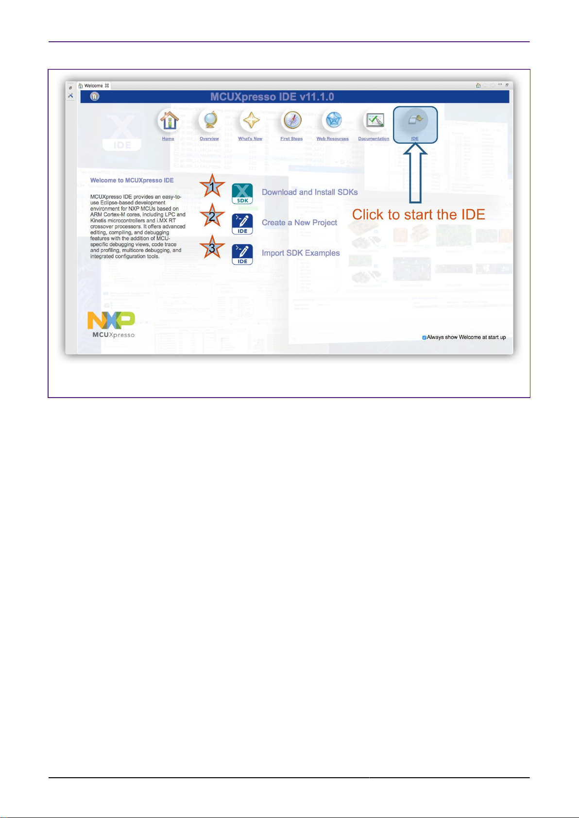
3.1 Workspaces
When you first launch MCUXpresso IDE, you will be asked to select a Workspace, as shown
in Figure 3.1.
Figure 3.1. Workspace selection
A Workspace is simply a filing system directory used to store projects and data, and the
recommended default location should typically be accepted for new installations. If you tick the
Use this as the default and do not ask again option, then MCUXpresso IDE will always start
up with the chosen Workspace opened; otherwise, you will always be prompted to choose a
Workspace.
MCUXpresso IDE can only access a single Workspace at a time but many Workspaces may
be used. You may change the Workspace that MCUXpresso IDE uses, via the File -> Switch
Workspace option.
Tip
It is possible to run multiple instances of the IDE in parallel with each instance
accessing a different Workspace.
Note: when changing workspaces, you may choose to copy settings (preferences) from an
existing workspace to the new workspace using the various Copy Settings tick box options.
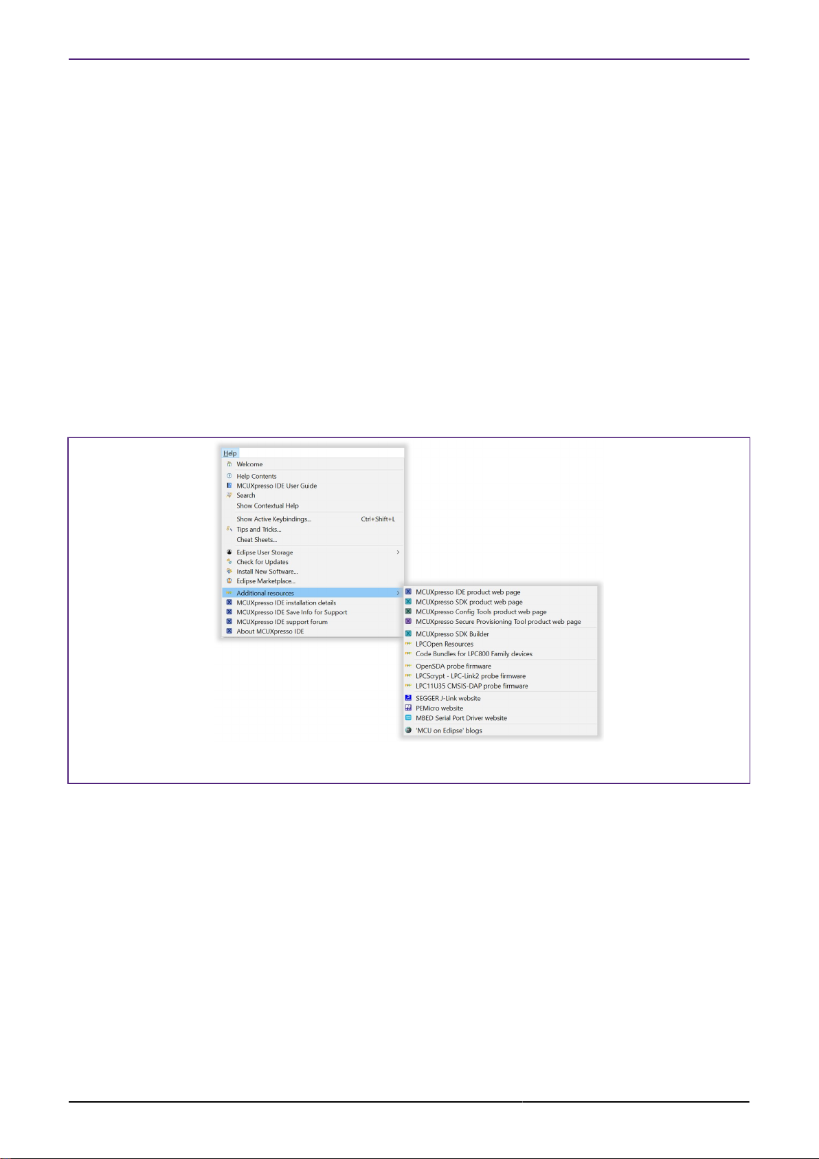
3.2 Welcome View
MCUXpresso IDE version 11.1.0 launches with a new Welcome View. This View is intended to
help reduce the learning curve for new users by offering links and help for common tasks and
IDE operations.
MCUXpresso IDE User Guide -
User Guide
All information provided in this document is subject to legal disclaimers
Rev. 11.3.1 — 2 April, 2021
© 2021 NXP Semiconductors. All rights reserved.
12
Page 21
NXP Semiconductors MCUXpresso IDE User Guide
Figure 3.2. Welcome View
1. Click to select, download and install a Plugin SDK [26]
2. Click to be guided through Creating a New Project [44]
3. Click to be guided through Importing an Example [53]
Since support for most NXP MCUs is added to the IDE via the installation of an SDK, the first
option is to guide the user to a new Plugin SDK [26] installation view. From this view, an SDK
for a required MCU or (development board) can be selected, downloaded and installed with just
a few clicks. Also from this screen are guided workflows for creating New Projects and Installing
SDK Examples.
Across the top of this View are links to Features and Resources including a jump to IDE
link (highlighted above) which takes the user directly to the IDE’s main development view
(Perspective).
Note: This Welcome View is provided by Eclipse functionality and so incorporates standard icons
to maximise, minimise and restore etc. like all Eclipse views. Since this view is intended to be
used full screen, minimising or restoring may lead to a poor screen layout. The recommended
way to switch back to the main IDE Develop view is via the IDE link or by closing this Welcome
Screen. The Welcome View can be restored at any time by clicking the Home Icon within the
main Eclipse Icon view.
The Welcome view can be disabled from appearing at startup by unchecking the box at the lower
right of the view.
3.3 Documentation and Help
MCUXpresso IDE User Guide -
User Guide
In addition to the help features offered from the Welcome View are a comprehensive suite of
Guides.
All information provided in this document is subject to legal disclaimers
Rev. 11.3.1 — 2 April, 2021
© 2021 NXP Semiconductors. All rights reserved.
13
Page 22
NXP Semiconductors MCUXpresso IDE User Guide
MCUXpresso IDE is based on the Eclipse IDE framework, and many of the core features are
described well in generic Eclipse documentation and in the help files to be found on MCUXpresso
IDE’s Help -> Help Contents menu. It also provides access to the MCUXpresso IDE User Guide
(this document), as well as the documentation for the compiler, linker, and other underlying tools.
MCUXpresso IDE documentation comprises a suite of documents including:
• MCUXpresso IDE Installation Guide
• MCUXpresso IDE User Guide (this document)
• MCUXpresso IDE SWO Trace Guide
• MCUXpresso IDE Instruction Trace Guide
• MCUXpresso IDE LinkServer Energy Measurement Guide
• MCUXpresso IDE FreeRTOS Debug Guide
• MCUXpresso (IDE) Config Tools User’s Guide
These Guides are also supplied in PDF format within the MCUXpresso IDE’s installation folder.
To obtain assistance on using MCUXpresso IDE, visit: http://www.nxp.com/mcuxpresso/ide
Related web links can be found at Help -> Additional resources as shown below:
Figure 3.3. Additional Resources
3.4 Perspectives and Views
The overall layout of the main MCUXpresso IDE window is known as a Perspective. Within
each Perspective are many sub-windows, called Views. A View displays a set of data in the IDE
environment. For example, this data might be source code, hex dumps, disassembly, or memory
contents. Views can be opened, moved (dragged), docked, and closed, and the layout of the
currently displayed Views can be saved and restored.
Typically, MCUXpresso IDE operates using the single Develop Perspective, under which both
code development and debug sessions operate as shown in Figure 3.6. This single perspective
simplifies the Eclipse environment, but at the cost of slightly reducing the amount of information
displayed on screen.
Alternatively, MCUXpresso IDE can operate in a “dual Perspective” mode such that the C/
C++ Perspective is used for developing and navigating around your code and the Debug
Perspective is used when debugging your application.
MCUXpresso IDE User Guide -
User Guide
All information provided in this document is subject to legal disclaimers
Rev. 11.3.1 — 2 April, 2021
© 2021 NXP Semiconductors. All rights reserved.
14
Page 23
NXP Semiconductors MCUXpresso IDE User Guide
Note: when within the debug perspective, the concept of a selected project remains. The Blue
Debug button tool tip will display this selected project. Also, if a debug operation is started within
the Debug perspective and a switch is made to the Develop perspective, the IDE will automatically
open a debug stack view to display the active debug connection.
You can manually switch between Perspectives using the Perspective icons in the top right of
the MCUXpresso IDE window, as shown in Figure 3.4.
Figure 3.4. Perspective selection
New perspectives can be selected by clicking the view+ icon. Once a view has been selected,
its icon will appear within the horizontal section as highlighted above.
All Views in a Perspective can also be rearranged to match your specific requirements by
dragging and dropping. If a View is accidentally closed, it can be restored by selecting it from the
Window -> Show View dialog. The default layout for a perspective can be restored at any time
via Window -> Perspective -> Reset Perspective.
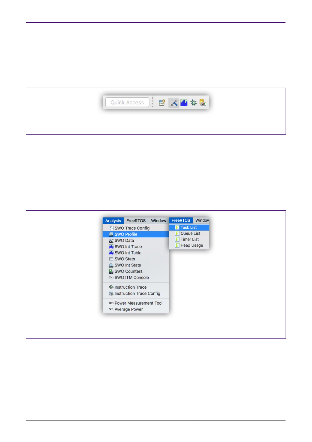
Commonly used Views for Analysis (Trace) and RTOS debugging have been made more readily
available via top level drop down menus as shown below:
Figure 3.5. Additional Views
MCUXpresso IDE User Guide -
User Guide
One selected, these additional views will appear alongside the Console view but can be relocated
as desired.
Note: The rest of this guide assumes the default Develop Perspective is used.
All information provided in this document is subject to legal disclaimers
Rev. 11.3.1 — 2 April, 2021
© 2021 NXP Semiconductors. All rights reserved.
15
Page 24
NXP Semiconductors MCUXpresso IDE User Guide
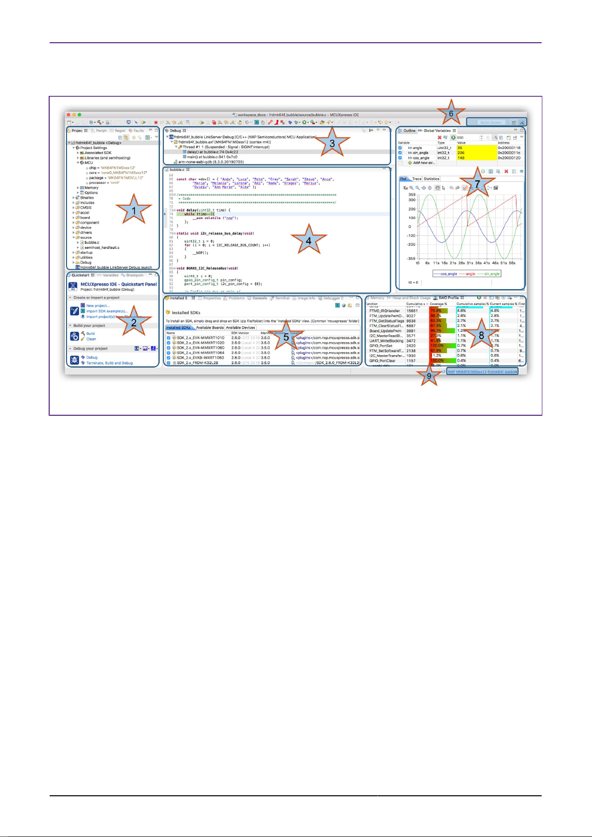
3.5 Major Components of the Develop Perspective
Figure 3.6. Develop Perspective (whilst debugging)
1. Project Explorer / Peripherals / Registers / Faults
• The Project Explorer view (shown) gives you a view of all the projects within your current
Workspace. [12]
• Many editing and configuration features are available from this view including new Project
Sharing [39] options and Virtual Nodes [134]
• When debugging, the Peripherals view allows you to display a list of the MCU
Peripherals [120] and project memory regions. Selecting a peripheral or memory region
will spawn a new window to display the detailed content. Note: depending on your MCUs
configuration, some peripherals may not be powered/clocked and hence their content will
not display.
• When debugging, the improved Registers view allows you to view the Registers [115]
and their content within the CPU of your MCU.
• Pseudo registers are also displayed here such as ‘cycle delta’ which shows the calculated
number of cycles since the last pause
• Also displayed here is the Faults view, which will appear automatically if a CPU Fault [118]
(such as hard fault) occurs. This view decodes CPU registers to provide detailed information
indicating the reason for the fault occurring.
2. Quickstart / Variables / Breakpoints
• On the lower left of the window, the Quickstart Panel View (shown) has fast links to
commonly used features. From here you can launch various wizards including New Project,
Import projects from SDK and also from the File System plus options such as Build, Debug,
Export etc.. The large icon in each section will perform the first option in the group i.e.
New project, Build, Debug. Also, the Debug group contains debug solution specific Debug
Shortcut buttons [104].
• Note: This Panel is essential to the operation of MCUXpresso IDE and so cannot be
removed from the perspective.
• Sitting in parallel to the Quickstart Panel, the Variables View allows you to see and edit
the values of local variables.
MCUXpresso IDE User Guide -
User Guide
All information provided in this document is subject to legal disclaimers
Rev. 11.3.1 — 2 April, 2021
© 2021 NXP Semiconductors. All rights reserved.
16
Page 25

NXP Semiconductors MCUXpresso IDE User Guide
• Sitting in parallel to the Quickstart Panel, the Breakpoints View allows you to see and
modify currently set Breakpoints [112] and Watchpoints [113] .
3. Debug
• The Debug View appears when you are Debugging [95] your projects. This view shows
you the debug stack, in the “stopped/paused” state you can click within the stack and inspect
items in scope such as local variables.
4. Editor
• Centrally located is the Editor, which allows creation and editing of source code and other
text files. When debugging, this is where you can see the code you are executing and can
step from line to line. By pressing the 'i->' icon at the top of the Debug view, you can switch
to stepping from source to assembly instructions. Clicking in the left margin will set and
delete Breakpoints [112]
• Enhanced Editors [181] provides structure, keyword and linkage for debug Map files,
Linker Script and Linker Template files.
5. Console / Installed SDKs / Problems / Trace Views / Power Measurement
• On the mid lower of the window are Console, Installed SDK and Problems Views etc. The
Console View displays status information on compilation and debug operations, as well as
displaying semihosted program output.
• The Installed SDK [24] view (shown) enables the management of installed SDKs.
New SDKs can be added as Plugins via Drag and Drop or Copy and Paste. Other SDK
management features are also provided from this view including unzip, explore and delete.
Details of any selected SDK can be viewed in Outline view.
• SDK Documentation can be browsed and extracted
• The Problems View shows all compiler errors and warnings and will allow easy navigation
to the error location in the Editor View.
• The Image Information View
• This Image Information [175] view provides detailed information on an image (or object)
static memory footprint (usage and content).
6. Quick Access/Perspective Selection
• Enables quick access to features such as views, perspectives etc. for example enter ‘Error’
to view and open the IDE’s Error Log, or ‘Trace’ to view and open the various LinkServer
Trace views.
• Perspective Selection allows you to switch between the various defined perspectives.
7. Outline / Global Variables
• The Outline View allows you to quickly locate symbols, declarations, functions within the
editor view. This view can also display details of any SDK selected in the Installed SDK view.
• Sitting in parallel is the Global Variables View (shown) which allows you to see and edit
the values of Global variables.
• Variables can be monitored while the target is running using the Live Variables [123]
and Variable Graphing [126] features.
8. Memory / Heap and Stack / Trace
• The Memory View provides a range of options for viewing target memory
• The Heap and Stack View enables easy monitoring of Heap and Stack [129] values for
bare metal projects.
• Warnings are given when preset limits are approached or exceeded
• Trace Views
• Trace Views including SWO Trace (Profiling shown), Instruction Trace, and Power are not
shown on this screenshot, however these views may be selected when required from the
Analysis Menu. For more information on Trace functionality, please see the MCUXpresso
IDE SWO Trace Guide and/or the MCUXpresso IDE Instruction Trace Guide and/or the
MCUXpresso IDE LinkServer Power Measurement Guide.
• The SWO Trace Views allow you to gather and display runtime information using the
SWO/SWV technology that is part of Cortex-M3/M4/M7/M33 based parts.
• The Instruction Trace view on certain MCUs, you can capture and view instruction trace
data downloaded from the MCU’s Embedded Trace Buffer (ETB) or Micro Trace Buffer
(MTB).
MCUXpresso IDE User Guide -
User Guide
All information provided in this document is subject to legal disclaimers
Rev. 11.3.1 — 2 April, 2021
© 2021 NXP Semiconductors. All rights reserved.
17
Page 26
NXP Semiconductors MCUXpresso IDE User Guide
• The Power Measurement View, this view is capable of displaying real-time target power
usage. For more information please see the MCUXpresso IDE Power Measurement
Guide.
9. Status Bar Shortcuts
• Various useful shortcuts, for example to open a project’s workspace or to open a terminal
at the project’s location with the IDE’s environment. Hover here and tooltips will explain the
various options.
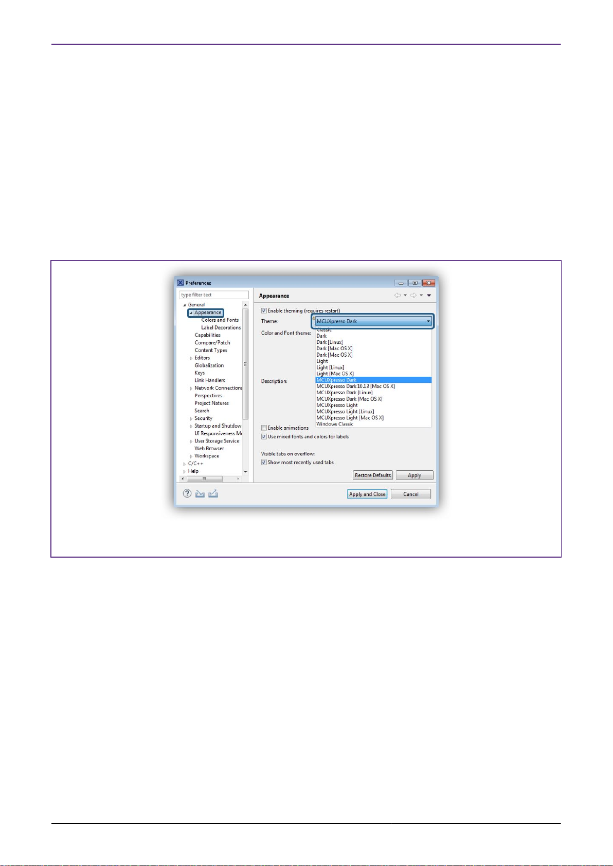
3.5.1 Dark Theme
MCUXpresso IDE contains support for a Dark Theme. Dark Theme is a Workspace preference
that can be selected from Window -> Preferences -> Appearance -> Theme followed by a
selection from the drop down menu.
Figure 3.7. Appearance Preference
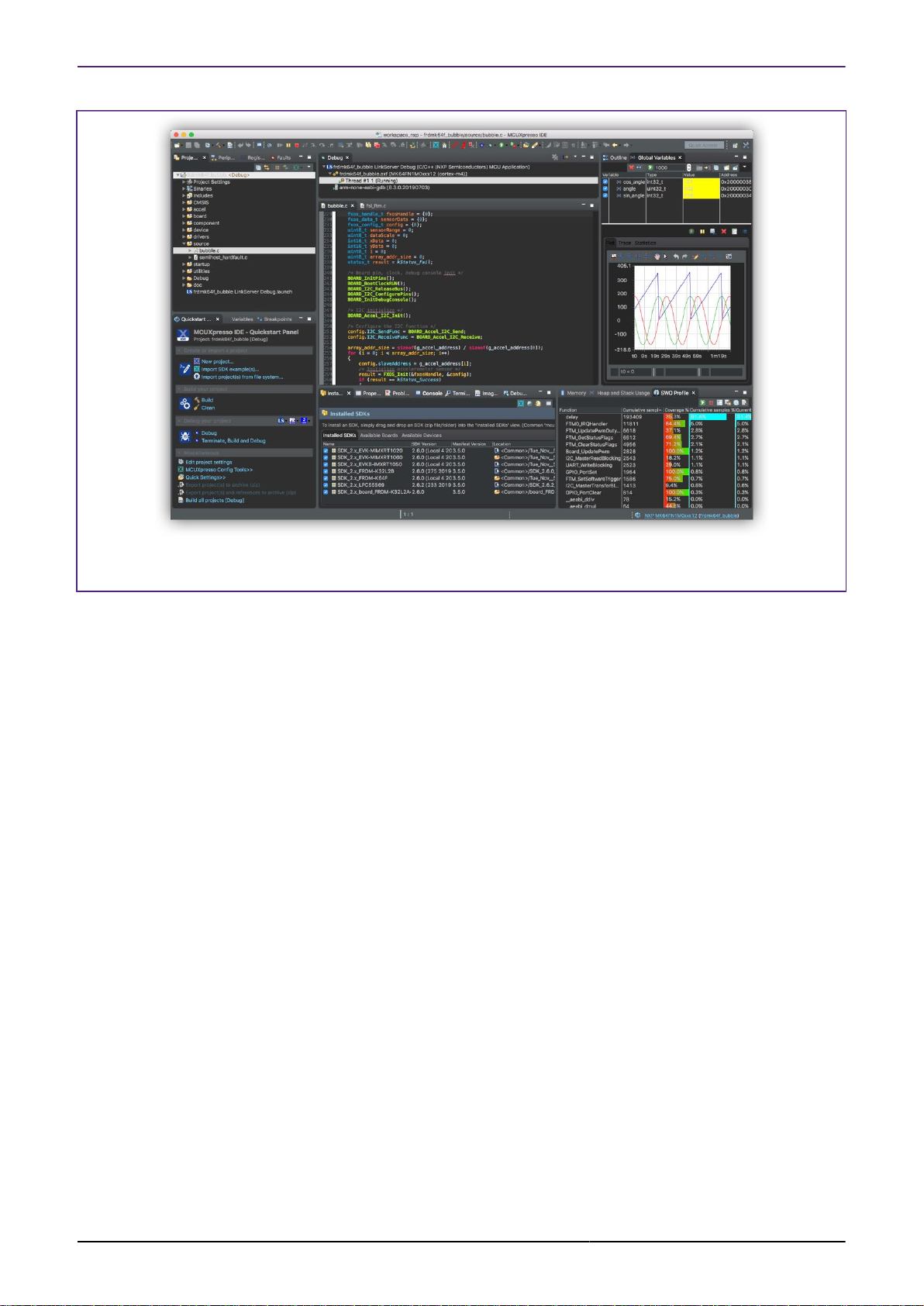
When selected, a Dark theme with be used to render the perspective and will appear similar to
the image below:
MCUXpresso IDE User Guide -
User Guide
All information provided in this document is subject to legal disclaimers
Rev. 11.3.1 — 2 April, 2021
© 2021 NXP Semiconductors. All rights reserved.
18
Page 27
NXP Semiconductors MCUXpresso IDE User Guide
Figure 3.8. Develop Perspective Dark
Note: An IDE restart File -> Restart is required for the perspective to display correctly.
3.6 The Quickstart Panel
A key feature of MCUXpresso IDE is the Quickstart Panel – which is frequently referenced
with this document. The Quickstart panel is designed to bring together many of the common IDE
features and operations including links to Project Creation, Project Building, Project Debug and
Miscellaneous common Project operations.
It is strongly recommended that this panel is used to perform the supported MCUXpresso
IDE operations described below since many underlying Eclipse features are enhanced when
accessed in this way to improve and simplify the user experience.
Features of the Panel are highlighted and described below:
MCUXpresso IDE User Guide -
User Guide
All information provided in this document is subject to legal disclaimers
Rev. 11.3.1 — 2 April, 2021
© 2021 NXP Semiconductors. All rights reserved.
19
Page 28
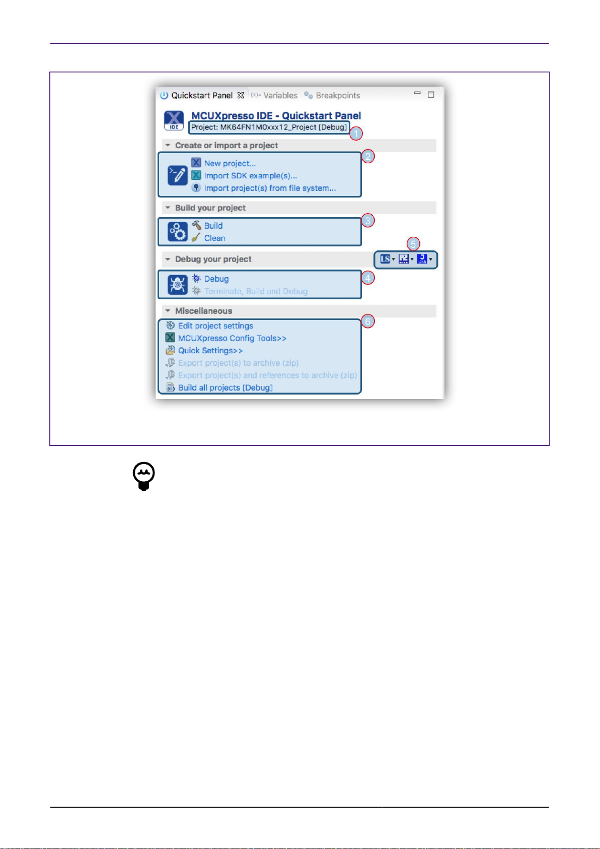
NXP Semiconductors MCUXpresso IDE User Guide
Figure 3.9. The Quickstart Panel
Tip
The Large Icon performs the action of the first button in the group
Where:
1. Shows the Project currently selected within the Project Explorer view. Build, Debug and
Miscellaneous operations will be performed to this Project
2. Links to Create New [44], Import SDK [53] and Import from the FileSystem [71]
3. Build [51] (or Clean) the currently selected Project
• See progress and results within the Console [244] view
4. Debug the currently selected Project
• Clicking Debug [95] will by default Build the project (if necessary), perform a Debug Probe
Discovery, create a default Launch Configuration [78] (if necessary) and if successful,
begin the debug session.
• Terminate, Build and Debug, Terminates the existing Debug session for the selected project,
and them performs another debug operation. It is intended to be used for iterative source
code fix and debug retry operations
5. Debug Shortcuts [104] offer a range of debug operations for specific vendor Debug Solutions
6. The Miscellaneous section offers a range of option and shortcuts
• Edit project settings is a shortcut equivalent to a right click on a project and then selecting
Properties
• MCUXpresso Config [137] Tools offers shortcuts to launch one of the Config tools for the
selected project
• Quick Settings [133] offers a range of options for the currently selected project
MCUXpresso IDE User Guide -
User Guide
All information provided in this document is subject to legal disclaimers
Rev. 11.3.1 — 2 April, 2021
© 2021 NXP Semiconductors. All rights reserved.
20
Page 29
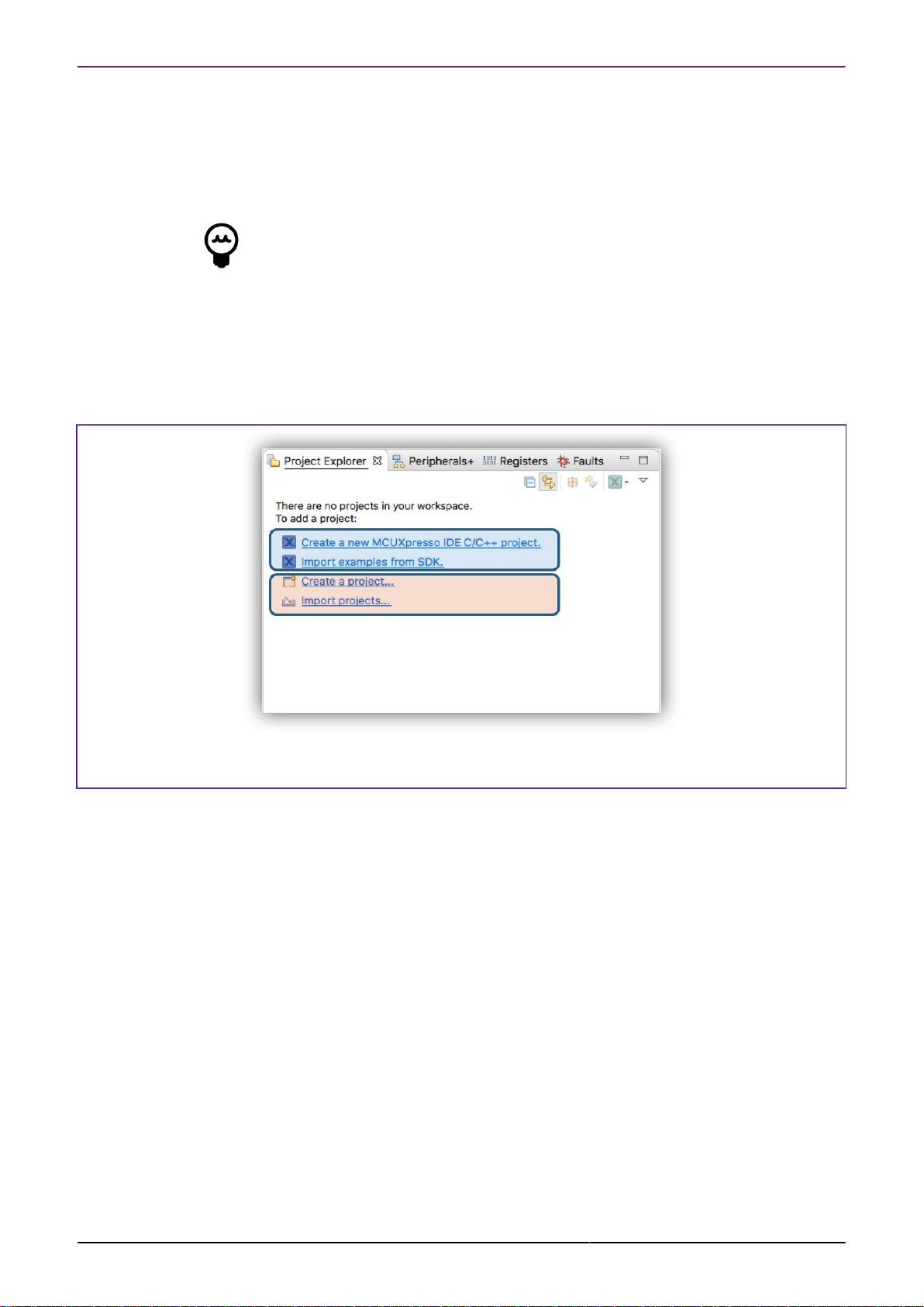
NXP Semiconductors MCUXpresso IDE User Guide
• Export the selected Project (and References) to the file system. See also additional
information on Sharing Projects [39]
• this feature requires that the project is selected at the top level within Project Explorer
• Build the Active Build Configuration of all projects within the current Workspace.
Tip
If the Quickstart panel has become hidden, then in the menu bar at the top of the IDE,
select Window -> Show View -> MCUXpresso IDE and double-click on Quickstart
3.7 Project Explorer and New Projects
The version of Eclipse underlying MCUXpresso IDE incorporates some new Project Explorer
functionality that is seen only when there are no projects within the chosen Workspace [12]
- as shown below:
Figure 3.10. Project Explorer Empty
The first two options here are directly equivalent to the first two operations offered via the
Quickstart panel. It is recommended that the Quickstart is used in preference to the remaining
options since this ensures that MCUXpresso IDE wizards and functionality is used.
Note: Due to this Eclipse feature, Drag and Drop functionality to the Project Explorer view is
unavailable until the first project is created or imported.
New or Imported Projects will appear in the Project Explorer view. A newly created project will
automatically expand to show the source file containing the main function. This source file will
also be opened into the editor for convenience as shown below.
MCUXpresso IDE User Guide -
User Guide
All information provided in this document is subject to legal disclaimers
Rev. 11.3.1 — 2 April, 2021
© 2021 NXP Semiconductors. All rights reserved.
21
Page 30
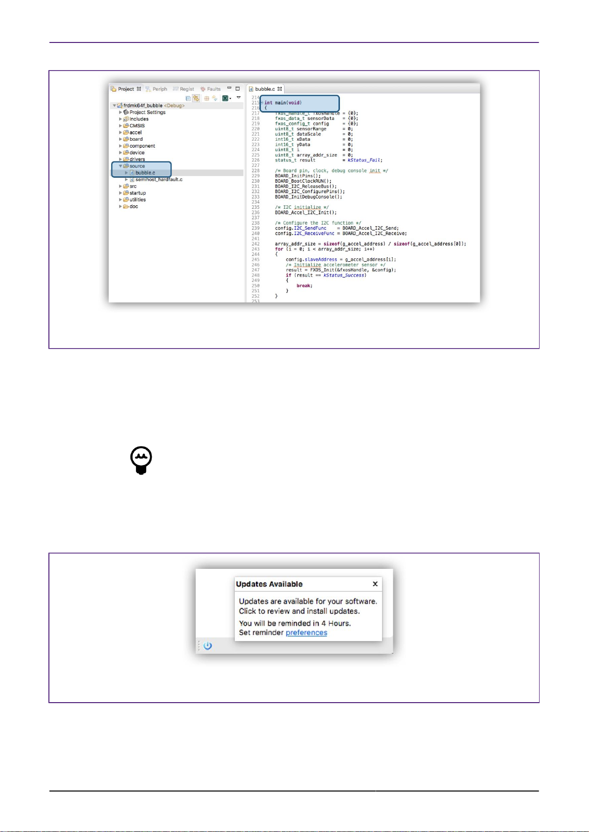
NXP Semiconductors MCUXpresso IDE User Guide
Figure 3.11. New or Imported Project
3.8 Updating MCUXpresso IDE
MCUXpresso IDE incorporates the facility to update an installation to add new features, updates
and/or to roll out bug fixes etc. To facilitate this mechanism, MCUXpresso IDE version internals
locate key components with Eclipse style plugins.
Tip
Locating low level components can be difficult due to both the complex directory
structure but also because component locations may change after an update is
performed. Therefore, to simplify the experience a number of softlinks are available
within the install_dir/ide as discussed in section below “Locating IDE Components”
By default, when an update is released by NXP, a notification of the availability will appear at
the bottom of the screen.
Figure 3.12. Update Notification
Alternatively you can check for updates via Help -> Check for Updates. If updates are available
you will be presented with a dialogue similar to that below:
MCUXpresso IDE User Guide -
User Guide
All information provided in this document is subject to legal disclaimers
Rev. 11.3.1 — 2 April, 2021
© 2021 NXP Semiconductors. All rights reserved.
22
Page 31

NXP Semiconductors MCUXpresso IDE User Guide
Figure 3.13. Updating MCUXpresso IDE Components
Simply, ensure the required updates are checked and click Next. At this point the components will
be downloaded and installed into MCUXpresso IDE. After installation, a restart will be required
before new features are available.
Note: In addition to updates for MCUXpresso IDE, updates to the MCUXpresso Config tools and
PEMicro debug solution are also delivered using this mechanism.
Major product releases will only be delivered as full product installations since these are
typically based on newer versions of Eclipse
3.8.1 Locating IDE Components
MCUXpresso IDE consists of many components, some of which may be used independently
from the IDE. Also included are documents, examples, scripts, drivers etc. that may need to be
referenced from within the IDE.
Due to the structural changes introduced in MCUXpresso IDE version 10.3.0, the paths for certain
items may be both different from previous releases and may change after a product update (and
also be quite long). For example, the IDE bin folder will now be at a location of the form:
<install_dir>/ide//plugins/com.nxp.mcuxpresso.tools.bin.macosx_11.1.0.201911211415/binaries
Therefore, to simplify the location of certain folders, shortcuts (or symbolic links) are installed
into the ide directory within the product’s installation directory. These links can be used directly
to locate components or items, or within script paths.
Shortcuts are available for the following directories:
MCUXpresso IDE User Guide -
User Guide
• bin -> install_dir/ide/bin
• Examples -> install_dir/ide/Examples
• Wizards -> install_dir/ide/Wizards
• tools -> install_dir/ide/tools
In practice, these links will allow paths to be used unchanged from earlier version of
MCUXpressoIDE, yet will always reference the latest plugin components.
All information provided in this document is subject to legal disclaimers
Rev. 11.3.1 — 2 April, 2021
© 2021 NXP Semiconductors. All rights reserved.
23
Page 32

NXP Semiconductors MCUXpresso IDE User Guide
4. Part Support Overview (Preinstalled and via SDKs)
To support a particular MCU (or family of MCUs) and any associated development boards, a
number of elements are required. These break down into:
• Startup code
• This code will handle specific features required by the MCU
• Memory Map knowledge
• The addresses and sizes and types of all memory regions
• Peripheral knowledge
• Detailed information allowing the MCUs peripherals registers to be viewed and edited
• Flash Drivers
• Routines to program the MCU’s on and off chip Flash devices as efficiently as possible
• Debug capabilities
• Knowledge of the MCU debug interfaces and features (e.g. SWO, ETB)
• Example Code (this is not strictly required or a part support element)
• Code to demonstrate the features of the particular MCU and supporting drivers
Collectively, this data is known as Part Support, MCUXpresso IDE uses these data elements for
populating its wizards and for built in intelligence features, such as the automatic generation of
linker scripts etc.
MCUXpresso IDE installs with a base set of part support primarily for older LPC Devices
(Preinstalled). Knowledge of later devices such as the LPC5xxxx, Kinetis, iMXRTxxx etc. must
be provided to the IDE via the installation of an SDK [26] .
4.1 Preinstalled Part Support
The IDE installs with an enhanced version of the part support as provided with the older NXP
IDE LPCXpresso IDE v8.2.2. This provides support for the majority of LPC Cortex-M based parts
‘out of the box’. This is known as preinstalled part support. In general, SDKs are not available for
these older parts however, the LPC5410x and LPC5411x part families can be used with either
Preinstalled Part Support or SDK Part support.
Example code for these preinstalled parts is provided by sophisticated LPCOpen packages (and
Code Bundles). Each of these contains code libraries to support the MCU features, LPCXpresso
boards (and some other popular ones), plus a large number of code examples and drivers.
Version of these are installed by default at:
<install dir>/ide/Examples/LPCOpen
<install dir>/ide/Examples/CodeBundles
Further information can be found at:
http://www.nxp.com/lpcopen
4.1.1 Differences in Preinstalled and SDK Part Handling
MCUXpresso IDE User Guide -
User Guide
https://www.nxp.com/LPC800-Code-Bundles
Since SDKs combine part (MCU) and board support into a single package, MCUXpresso IDE
is able to provide linkage between SDK installed MCUs and their related boards when creating
or importing projects.
For preinstalled parts, the board support libraries are provided within LPCOpen packages and
Code Bundles. It is the responsibility of the user to match an MCU with its related LPCOpen
board and chip library when creating or importing projects.
All information provided in this document is subject to legal disclaimers
Rev. 11.3.1 — 2 April, 2021
© 2021 NXP Semiconductors. All rights reserved.
24
Page 33

NXP Semiconductors MCUXpresso IDE User Guide
Creating and importing project using Preinstalled and SDK part support is described in the
following chapters.
Note: When exporting or sharing projects with created with Preinstalled part support, no special
actions are required, since other installations of MCUXpresso IDE will also contain the required
part support. For sharing projects created from SDKs, please see Sharing Projects. [39]
4.1.2 Viewing Preinstalled Part Support
When MCUXpresso IDE is installed, it will contain preinstalled part support for most LPC based
MCUs.
To explore the range of preinstalled MCUs simply click ‘New project’ in the Quickstart panel.
This will open a page similar to the image below:
Figure 4.1. New Project Wizard
The list of preinstalled parts is presented on the bottom left of this window.
You will also see a range of related development boards indicating whether a matching LPCOpen
Library or Code Bundle is available.
For creating project with preinstalled part support please see: Creating Projects with Preinstalled
part support [64]
If you intend to work on an MCU that is not available from the range of preinstalled parts, for
example a Kinetis MCU, then you must first extend the part support of MCUXpresso IDE by
installing the appropriate MCU SDK.
MCUXpresso IDE User Guide -
User Guide
All information provided in this document is subject to legal disclaimers
Rev. 11.3.1 — 2 April, 2021
© 2021 NXP Semiconductors. All rights reserved.
25
Page 34

NXP Semiconductors MCUXpresso IDE User Guide
4.2 SDK Part Support
The IDE’s Part Support can be extended using freely available MCUXpresso SDK v2.x packages.
SDK 2.x packages are used to add support for all Kinetis, iMX RT and newer LPC MCUs etc.
Starting with MCUXpresso IDE version 11.1.0 there is a streamlined approach to the supply
and installation of SDKs – these SDKs are known as Plugin SDKs. Plugin SDKs are pre-built
SDKs hosted on NXP’s servers that can be browsed, downloaded and installed directly from
within the IDE when required. See Obtaining and Installing a Plugin SDK [26]
Each SDK will install as an Eclipse plugin and so benefit from the standard Eclipse management
and update mechanisms. MCUXpresso IDE Plugin SDKs are available for a wide range of
NXP’s MCUs. Like all Eclipse plugins, once Plugin SDKs are installed, they become part of
the product itself. Management of a Plugin SDK can be performed using the standard Eclipse
mechanisms [32]
The previous Classic method of SDK installation and handling is still available. See SDK Part
Support via SDK Builder [28]
Once an SDK has been installed, the included part support becomes available through the
New Project Wizard and also the SDK example import Wizard, and for use by imported
projects. [39]
4.2.1 Obtaining and Installing a Plugin SDK
SDKs are installed and managed via the Installed SDKs view, which is located by default as
the first tab within the Consoles view. See Major Components [16] item 3 for more information.
Plugin SDK installation can also be started via the New Welcome system and via the Install New
MCUXpresso SDK icon on the main IDE icon bar.
Once launched a dialogue similar to that below will be displayed:
Figure 4.2. Plugin SDK Installation
1. From this section the SDK for the desired Board (or Processor) can be selected for installation.
Column sorting is supported to help location and options for filtering the list are discussed
below
MCUXpresso IDE User Guide -
User Guide
All information provided in this document is subject to legal disclaimers
Rev. 11.3.1 — 2 April, 2021
© 2021 NXP Semiconductors. All rights reserved.
26
Page 35

NXP Semiconductors MCUXpresso IDE User Guide
• By default, SDKs that are already installed are hidden from this view
• If the Hide Installed is unchecked, installed SDKs will also be shown along with Status
indication for the SDKs already installed (shown as red circle)
2. A range of filtering options may be selected to reduce the list of displayed SDKs. These filters
allow the user to explore the capabilities of the MCUs and Boards.
3. Once an SDK has been selected it can be installed (with options)
• Install and Create Project will Download, Install and launch the New Project Wizard with
the chosen board selected
• Install and Import Example will Download, Install and launch the Import SDK Example
Wizard with the chosen board selected
• Install will Download and Install
Note: On rare occasions, it may be necessary to manually force a refresh of the cached contents
of the remote repository – and this can be performed via the button highlighted above.
Once an SDK (or SDKs) is selected and an install operation begun, you will be presented with
an option to accept the SDK license condition as below:
Figure 4.3. Plugin SDK Installation License
Download and install progress can be monitored via the Installation dialogue:
Figure 4.4. Plugin SDK Installation Progress
If Run in Background is clicked, control is returned to the IDE, of course the SDK will not become
available until download and installation completes – at this time a Wizard may be launched if
a Create or Import option was chosen. While the Plugin SDK Installer may be restarted, any
existing SDK installations must complete before another Install can be started.
Note: When the IDE is started for the first time, data for this display is automatically loaded in
the background. If the Plugin SDK Installer is started promptly after the IDE starts, there may be
a short pause while the data populates.
MCUXpresso IDE User Guide -
User Guide
All information provided in this document is subject to legal disclaimers
Rev. 11.3.1 — 2 April, 2021
© 2021 NXP Semiconductors. All rights reserved.
27
Page 36

NXP Semiconductors MCUXpresso IDE User Guide
4.2.2 SDK Part Support via SDK Builder
NXP also provides SDKs for toolchains (including MCUXpresso IDE) via their SDK Builder site.
Through this this site (login required), NXP MCU users may request builds for NXP MCUs that can
be configured to include a range of software features. Once built, the SDK can be downloaded
and installed into MCUXpresso IDE – this is the Classic method for installing SDKs as used in
all previous versions of MCUXpresso IDE. SDKs installed in this way are now referred to as
FileSystem SDKs since they become a shared resource for any IDE installation rather than part
of a particular IDE installation.
These SDKs can be installed via a simple ‘drag and drop’ mechanism which will then
automatically enhance the IDE with new part and board knowledge (and usually a large range
of examples).
SDKs for MCUXpresso IDE can be generated and downloaded as required using the SDK Builder
on the MCUXpresso Tools website at:
http://mcuxpresso.nxp.com/
Important Note: Only SDKs built specifically for MCUXpresso IDE are compatible with
MCUXpresso IDE. SDKs created for any other toolchain will not work! Therefore, when
generating an SDK be sure that MCUXpresso IDE is specified as the Toolchain.
4.2.3 Obtaining and Installing an SDK via SDK Builder
Users of earlier versions of the IDE may be more familiar with this model of SDK build and
installation.
SDKs are installed and managed via the Installed SDKs view, which is located by default as the
first tab within the Console view. See Major Components [16] item 3 for more information.
SDKs are free to download (login is required); MCUXpresso IDE offers a link to the SDK portal
(shown below) from the Installed SDK Console view. From this portal, required SDKs can
be downloaded onto the host machine. Alternatively, go to Help -> Additional Resources ->
MCUXpresso SDK Builder ... to open this portal in an external browser.
MCUXpresso IDE User Guide -
User Guide
All information provided in this document is subject to legal disclaimers
Rev. 11.3.1 — 2 April, 2021
© 2021 NXP Semiconductors. All rights reserved.
28
Page 37

NXP Semiconductors MCUXpresso IDE User Guide
Figure 4.5. SDK Import
Once downloaded, an SDK package(s) can be installed by simply dragging from the downloaded
location into the Installed SDKs view. Once dropped, you be prompted with a dialog asking you
to confirm the import – click OK. The SDK package(s) will then be automatically installed into
MCUXpresso IDE part support repository.
Once complete the “Installed SDKs” view will update to show you the package(s) that you have
just installed.
Figure 4.6. SDK Import View
MCUXpresso IDE User Guide -
User Guide
By default, SDKs will install into a Common folder and will therefore be available to any
MCUXpresso IDE instance. Alternatively SDKs can be installed into the current Workspace so
making their installation local to that Workspace. The selected install location is shown in the
SDK Window text as highlighted above. Also highlighted is the new version information string
(displayed in grey), this feature allows different SDK builds to be distinguishable. Please also
see SDK Advanced Importing [34] for further information on SDK installation options.
SDK Notes:
All information provided in this document is subject to legal disclaimers
Rev. 11.3.1 — 2 April, 2021
© 2021 NXP Semiconductors. All rights reserved.
29
Page 38

NXP Semiconductors MCUXpresso IDE User Guide
• Released in parallel with MCUXpresso IDE version 11.3.1 are updated SDKs
(MCUXpressoSDK v2.9.x). These are indicated by their version 2.9.x and a manifest version
3.8.0 in the Installed SDK view. While older SDKs are still compatible with MCUXpresso IDE
version 11.3.1, it is recommended that users check and update to the latest available SDK
package.
• Installed SDK view tooltips display comprehensive version information
• MCUXpresso IDE can import an SDK as a zipped package or unzipped folder (or zipped
Plugin). Typically importing as a zipped package is expected.
• The main consequence of leaving SDKs zipped is that you will not be able to create (or
import projects) into a workspace with linked references back to the SDK source files.
• When an SDK is imported via drag and drop, required files are copied and the original file/folder
is unaffected. The copied files are installed into a default location allowing imported SDKs to be
shared among different IDE instances/installations and workspaces. Data from imported SDKs
is populate wizards with available MCU and board information. In addition they are parsed to
generate part support and make example projects and drivers available etc.
• By default, SDKs (like workspaces) are located in user local storage, this means they will
only be available to the user who performed the installation. Please also see SDK Advanced
Importing [34] for details of how a shared location could be used if needed.
• Once installed the part support provided by the SDKs is regenerated. This regeneration is
required because an MCUs part support may be specified (with different versions) within more
than one SDK. On rare occasions, it may be necessary to force a regeneration of SDK part
support, this can be done by clicking the Recreate and Reload button within the top right block
inside the Installed SDK view, or by right clicking within the view and selecting Recreate.
4.2.4 Installed SDKs Operations
The installed SDKs view now incorporated 3 tabs. In addition to the Installed SDKs tab, new
Available Boards and Available Devices tabs are provided. These tabs expose the supported
boards and devices provided by the installed SDKs and allow the direct invocation of New Project
and Example Import Wizards:
Figure 4.7. SDK Tabbed Views
MCUXpresso IDE User Guide -
User Guide
Various other operations are available from the Installed SDK view some from a right click menu
options:
All information provided in this document is subject to legal disclaimers
Rev. 11.3.1 — 2 April, 2021
© 2021 NXP Semiconductors. All rights reserved.
30
Page 39

NXP Semiconductors MCUXpresso IDE User Guide
Important Note: Plugin SDKs cannot be unzipped or deleted from this view, however they can
be converted to FileSystem SDKs [32] Do not attempt to manually modify a Plugin SDK in
any way, doing so could lead to a loss of SDK part support from the IDE. Plugin SDKs can only
be deleted using the Eclipse Plugin management mechanism [32]
From here you can perform many actions such as view associated embedded SDK
documentation that would otherwise require the unzipping and exploration of the SDK structure.
The Installed SDKs view will show whether the SDKs are stored as zipped archives or regular
folders. MCUXpresso IDE offers the option to unzip a filesystem SDK archives in place via a right
click option onto the selected SDK (as below).
Note: Unzipping an SDK may take some time and is generally not needed unless you wish to
make use of referenced files or perform many example imports (where some speed improvement
will be seen).
Once an SDK has been unzipped, its icon will be updated to reflect that it is now stored internally
as a folder.
MCUXpresso IDE User Guide -
User Guide
All information provided in this document is subject to legal disclaimers
Rev. 11.3.1 — 2 April, 2021
© 2021 NXP Semiconductors. All rights reserved.
31
Page 40

NXP Semiconductors MCUXpresso IDE User Guide
Figure 4.8. SDK Unzipped
Many other options are available such as examining SDK XML description files, Copying and
Pasting SDKs and managing the library of installed SDKs.
Tip
To edit (and save) SDK XML files, the SDK must first be unzipped and the following
preference changed: Preferences -> MCUXpresso IDE -> SDK Handling -> Misc,
uncheck the read only mode option. Once saved, changes will become permanent
for that SDK installation.
Tip
In addition to the other SDK options, an SDK can be pasted into the Installed SDK
view from the file system or another IDE instance.
Finally, SDK part support automatically regenerates when a new SDK is installed. If a project is
imported and the expected part support is not available then select Recreate from the right click
menu option to force a recreation of the SDK part support.
Converting a Plugin SDK into a FileSystem SDK
On occasion it may be useful to migrate a Plugin SDK to become a FileSystem SDK – for example
if you require the SDK to be unzipped or to be shared with other IDE installations. To do this
simply select the Plugin SDK within the Installed SDK view then from the right click menu select
Copy followed by Paste. This will launch an Import operation and copy the SDK contents from
the Plugin into the default SDK FileSystem location. This SDK will be used in preference to the
Plugin version.
Note: A Plugin SDK is a part of an IDE installation and can only be deleted via the Eclipse Plugin
management mechanism [32] .
Uninstalling (Deleting) an Installed SDK
Plugin SDKs become part of the IDE and so cannot simply be deleted. If for any reason it is
necessary to remove a Plugin SDK then this must be done via the Eclipse plugin management
mechanism. This can be launched via Help -> About -> Installation Details:
MCUXpresso IDE User Guide -
User Guide
All information provided in this document is subject to legal disclaimers
Rev. 11.3.1 — 2 April, 2021
© 2021 NXP Semiconductors. All rights reserved.
32
Page 41

NXP Semiconductors MCUXpresso IDE User Guide
Figure 4.9. Plugin SDK Delete
Note: A FileSystem SDK will always be used in preferences to a Plugin SDK, so a Plugin SDK
can effectively be replaced by the installation of a FileSystem SDK offering equivalent features.
If an SDK has been installed by the ‘Drag and Drop’ method, then a copy of the SDK will have
been installed into the Default Location. SDKs installed into this location can be uninstalled and
deleted via a right click option. Once an SDK has been uninstalled, part support will automatically
be recreated for the remaining SDKs. Please see Uninstallation Considerations [38] for more
information.
Alongside each installed SDK is a check box, if this is unchecked the SDK will be hidden
from MCUXpresso IDE until re-checked. If multiple SDKs are installed that contain shared part
support, then this feature may be useful to force the selection of part support from a particular
SDK. Please see Shared Part Support Handling [37] for more information.
SDKs installed into non default file system locations must be manually deleted or hidden if they
are no longer required. Note: you may have to quit MCUXpresso IDE to delete these SDKs.
Please see SDK Importing and Configuration [34] for more information.
4.2.5 Installed SDKs Features
You can explore each of the SDKs within the Installed SDKs View to examine content such as
Components, Memory Settings, included Examples etc.
MCUXpresso IDE User Guide -
User Guide
All information provided in this document is subject to legal disclaimers
Rev. 11.3.1 — 2 April, 2021
© 2021 NXP Semiconductors. All rights reserved.
33
Page 42

NXP Semiconductors MCUXpresso IDE User Guide
Figure 4.10. SDK Explore
4.2.6 Advanced Use: SDK Importing and Configuration
SDK importing via drag and drop incorporates two features. Firstly the location where the SDK
will be copied, and secondly the automatic scanning of this location to create the required
Part Support. The behaviour can be explored and changed via a preference Preferences ->
MCUXpresso IDE -> SDK Handling -> Installation leading to the window below:
MCUXpresso IDE User Guide -
User Guide
All information provided in this document is subject to legal disclaimers
Rev. 11.3.1 — 2 April, 2021
© 2021 NXP Semiconductors. All rights reserved.
34
Page 43

NXP Semiconductors MCUXpresso IDE User Guide
Figure 4.11. SDK Installation Preferences
You can see in the above graphic that two search locations are present. The 02 path is the
default search path for MCUXpresso IDE version 11.0, earlier versions of MCUXpresso IDE
used the 01 path. This older path will only appear if the location actually contains installed SDKs
(typically installed via an earlier version of MCUXpresso IDE). The reason for these separate
paths is to allow users to have both the latest and older versions of MCUXpresso IDE installed
without presenting incompatible versions of SDK to older versions of the tools. Please see SDK
compatibility with earlier versions of MCUXpresso IDE [37] for more information.
• Workspace
• Common (the default)
• User Defined
The default Common install location can be changed to either the currently selected Workspace
or a User Defined location. Once this is done, a new SDK Search Root path will automatically
be added to the search roots list.
Note: while other search roots can be removed if desired, the currently selected drag and drop
location root cannot.
In addition, from this dialogue you can add new search paths to folders where you have stored
or plan to store SDK folders/zips. Those SDKs will appear in the Installed SDKs View along with
those from the default location when the Installed SDK view is refreshed.
MCUXpresso IDE User Guide -
User Guide
The main differences between having SDKs in the default location(s) or leaving them in other
folders are:
All information provided in this document is subject to legal disclaimers
Rev. 11.3.1 — 2 April, 2021
© 2021 NXP Semiconductors. All rights reserved.
35
Page 44

NXP Semiconductors MCUXpresso IDE User Guide
• “Delete SDK” function is disabled when using non-default locations
• since these SDKs are not imported, they may be original files
• The knowledge of the SDKs and their part support is per-workspace
The order of the SDKs in the SDK location list may be important on occasion: if you have multiple
SDKs for the same part in various locations, you can choose which to load by reordering. If
multiple SDK are found, a warning is displayed into the Installed SDK view.
Note: Only the default SDK location(s) is persistent between workspaces. Any other locations
must be created for each Workspace as required.
Also displayed in the dialogue (above) are a number of ‘checkbox’ options that are discussed
below:
• Always Unzip SDK ... if checked, a zipped SDK will be unzipped on import.
• Do not ask for unzipping ... if checked (default) the IDE will not prompt the user to consider
unzipping the SDK.
• Do not ask for confirmation ... if checked, the IDE will import and SDK via drag and drop without
requesting user confirmation.
• Make missing SDK reference persistent ... this setting controls the persistence setting when
the option below is checked.
• Do not ask for User action ... see shared part support [37] - if checked, this SDK association
setting will be made without prompting the user.
• Enable SDK/manifest version... if multiple SDKs for the same part are installed, this option if
checked also allows an older SDK to be selected from within the Installed SDK view via a drop
down menu on the SDK Version
• also, some SDKs include older versions of the manifest (XML description) ... if checked, this
option allow an older manifest version to be selected from within the Installed SDK view via
a drop down menu on the Manifest Version.
• Automatically uninstall ... if checked an SDK found in drag and drop install location that is
incompatible with MCUXpresso IDE will be deleted.
4.2.7 Advanced Use: SDK Misc Options
Additional miscellaneous SDK preferences are also available. These checkbox options are
shown below:
Figure 4.12. SDK Preferences Misc
MCUXpresso IDE User Guide -
User Guide
Where:
All information provided in this document is subject to legal disclaimers
Rev. 11.3.1 — 2 April, 2021
© 2021 NXP Semiconductors. All rights reserved.
36
Page 45

NXP Semiconductors MCUXpresso IDE User Guide
• Prioritize IDE supplied flash drivers ... typically LinkServer flash drivers are supplied as part
of the SDK part support for a particular MCU. However these LinkServer flash drivers are
usually duplicated within the IDE installation where newer versions might be found. This option,
checked by default causes the IDE supplied drivers to be used in preference to SDK supplied
flash drivers. Searching the IDE’s flash driver directory in preference to SDK dynamically part
support files also simplifies flash driver development
• Default SDK debug console to semihost ... this option, checked by default, sets project defines
to select semihosting as the output format
• Include semihost hardfault handler ... this option, checked by default, causes a minimal
hardfault handler to be included within new and imported projects. The purpose of this handler
is to send semihost operations to null when no debug tools are connected. Without such a
handler, any semihosted operation will halt the MCU when no debug tools are connected. This
is probably the most useful option for early project development, however this may clash with
any real hardfault handler.
• Enable SDK options check ... this option, checked by default, allows the IDE to check an SDK
examples options on import and attempt to resolve any incompatible options found.
• Selected files from SDK view ... this option, checked by default, forces any file opened from
the Installed SDK view to be opened in Read Only mode. This is to protect SDK files from
accidental corruption. Note: this option only applies to SDK that are imported unzipped.
• Open Project main files ... when an example project is imported it will be opened within the
project explorer view and the source file containing the main function will be opened. This
option, unchecked by default, will allow this to occur if multiple files are imported at the same
time.
4.2.8 Important notes for SDK Users
Installing an SDK into MCUXpresso IDE adds to its default capabilities, but SDKs come in many
different configurations, and versions. The section below discusses some of the issues that users
may experience when working with SDKs.
Only SDKs created for MCUXpresso IDE can be used
If an error of the form MCUXpresso IDE was unable to load one or more SDKs is seen, the most
likely reason is that the SDK was not built for MCUXpresso IDE. Within the SDK Builder, verify
that the Toolchain is set to MCUXpresso IDE. If necessary, reset the toolchain to MCUXpresso
IDE and rebuild the SDK.
SDK compatibility with earlier versions of MCUXpresso IDE
A new SDK version 2.9.0 has been released in parallel with MCUXpresso IDE version 11.3.1
however, this SDK format includes features that are not compatible with earlier versions of
MCUXpresso IDE. As a result, these new SDKs may fail to install or offer reduced featured when
used in older versions of MCUXpresso IDE.
To support users who might have both this and also older versions of MCUXpresso IDE installed
on their system, we have adopted a new default SDK installation location but also maintained
support for the default used by older versions (now effectively Read Only from version 10.1.0
onwards).
The result of this is that MCUXpresso IDE version 10.1.0 and later will automatically inherit any
SDKs installed into the (old) default location by previous versions of the IDE. While older versions
of the IDE will not ‘see’ any SDKs installed with MCUXpresso IDE version 10.1.0 or later.
MCUXpresso IDE User Guide -
User Guide
Note: If there is no need to maintain compatibility with older versions of the IDE, it is
recommended that users migrate to using the latest SDKs where available.
Shared Part Support Handling
Each SDK package will contain part support for one or more MCUs, therefore it is possible
to have two (or more) SDK packages containing the same part support. For example, a user
All information provided in this document is subject to legal disclaimers
© 2021 NXP Semiconductors. All rights reserved.
Rev. 11.3.1 — 2 April, 2021
37
Page 46

NXP Semiconductors MCUXpresso IDE User Guide
might request a Tower K64 SDK and later a Freedom K64 SDK that both target the same
MK64FN1M0xxx12 MCU. If both SDKs are installed into the IDE, both sets of examples and
board drivers will be available, but the IDE will select the most up to date version of part support
specified within these SDKs. This means the various wizards and dialogues will only ever present
a single instance of an MCU, but may offer a variety of compatible boards and examples. Note: If
a board is selected (from one SDK) and part support is provided by another SDK, a message will
be displayed within the project wizard to show this has occurred but no user action is required.
If two SDKs with matching part support are installed, and the SDK providing part support later
deleted, then part support will automatically be used from the remaining SDK.
Finally, if a project created with one SDKs part support – for example Freedom K64, and then:
- that SDK is changed to another SDK with compatible part support – for example TWR K64 -
the project is shared with another user who has a different SDK that includes compatible part
support (perhaps an SDK that has only device support)
a dialogue similar to the one below will be generated for each project where this occurs:
Where the option to Make persistent will permanently change the project to be associated with
the selected SDK. If unticked, the IDE will accept the change as temporary and no data will be
written back to the project.
Note: When this new association is made, the project will contain files from one SDK but be
associated with another. If the project is refreshed or the component management feature is
used, then incompatible code may be copied into the project.
Building a Fat SDK
An SDK can be generated for a selected part (processor type/MCU) or a board. If just a part is
selected, then the generated SDK will contain both part support and also board support data for
the closest matching development board.
Therefore, to obtain an SDK with both Freedom and Tower board support for say the Kinetis
MK64... part, simply select the part and the board support will be added automatically.
If a part is chosen that has no directly matching board, say the Kinetis MK63… then the generated
SDK will contain:
• part support for the requested part i.e. MK63...
• part support for the recommended closest matching part that has an associated development
board i.e. MK64...
• board support packages for the above part i.e. Freedom and/or Tower MK64...
MCUXpresso IDE User Guide -
User Guide
Uninstallation Considerations
MCUXpresso IDE allows SDKs to be installed and uninstalled as required (although for most
users there is little benefit in uninstalling an SDK). However, since the SDK provides part support
All information provided in this document is subject to legal disclaimers
© 2021 NXP Semiconductors. All rights reserved.
Rev. 11.3.1 — 2 April, 2021
38
Page 47

NXP Semiconductors MCUXpresso IDE User Guide
to the IDE, if an SDK is uninstalled, part support will also be removed. Any existing project built
using part support from an uninstalled SDK will no longer build or debug. Such a situation can
be remedied by re-installing the missing SDK. Note: if there is another SDK installed capable of
providing the ‘missing’ part support, then this will automatically be used.
Sharing Projects
Note: Also see Enhanced Project Sharing Features [39] below:
If a project built using part support from an SDK and is then exported – for example to share the
project with a colleague who also uses MCUXpresso IDE, then the colleague must also install
an SDK providing part support for the projects MCU.
4.3 Enhanced Project Sharing Features
MCUXpresso IDE has a range of features designed to improve the ease of project sharing. These
features combine to streamline the sharing and collaboration process.
4.3.1 Project Drag and Drop
In addition to the existing project import and export capabilities available from the Quickstart
panel, a new set of features has been introduced to ease the transfer of projects.
Previously, the import of a project required browsing to a project location followed by an import.
Now ...
• Projects can now be imported into a Workspace by simply dragging and dropping a folder (or
zip) containing one or more projects into the Project Explorer view
• Projects can be copied from one IDE instance to another by simply dragging and dropping
from one Project Explorer view to another
Eclipse also offers the following functionality:
• Projects can also be exported by dragging from the Project Explorer view onto a host filer
• Warning: Care must be used here since the default Eclipse behaviour when dragging is
to move files from the workspace rather than performing a copy. This behaviour can be
modified to copy on Mac via holding the Option Key, and on Windows via holding Ctrl. Note
that if the underlying files of a project are moved, the project will remain visible within the
project explorer view but will no longer be usable. A project explorer refresh (F5) should be
performed.
Tip
If a project is moved accidentally (as described above), it can be re-imported by
dragging back from the filer location into to the project explorer view (the original
project must be removed first otherwise a clash of names will prevent import).
4.3.2 Project Local SDK Part Support
MCUXpresso IDE User Guide -
User Guide
One weakness of the SDK model of extending the capabilities of the IDE comes when sharing
projects with colleagues – since they must also have the same SDK installed to use this shared
project.
To avoid this problem, SDK projects (and examples) can be modified to contain a local copy of
the required SDK part support.
SDK project may be enhanced to contain local SDK part support
• SDK based projects can now import a cache of part knowledge from an installed SDK
All information provided in this document is subject to legal disclaimers
Rev. 11.3.1 — 2 April, 2021
© 2021 NXP Semiconductors. All rights reserved.
39
Page 48

NXP Semiconductors MCUXpresso IDE User Guide
• Simply right click on a project and select add SDK Part Support
Figure 4.13. Add SDK Local Part Support
• Such projects can then be used (in other user’s MCUXpresso IDEs version 10.2.0 or later)
without first downloading and installing the appropriate SDK
• In such cases, the project local part support will be visible as an installed SDK
Figure 4.14. View SDK Local Part Support
Note: this feature is not designed to replace the need for ultimately installing an SDK, since there
are implications in project size etc. rather it is intended as short term solution to decouple projects
from the requirement for an SDK.
MCUXpresso IDE User Guide -
User Guide
All information provided in this document is subject to legal disclaimers
Rev. 11.3.1 — 2 April, 2021
© 2021 NXP Semiconductors. All rights reserved.
40
Page 49

NXP Semiconductors MCUXpresso IDE User Guide
Finally, local part support can be removed in the same way as it was added. Simply right click on
a project and select SDK Management -> Remove SDK Part Support. Once this has been done,
an appropriate SDK must be installed for the project to be used.
4.3.3 Project Local Support files
Supporting files required for debug such as flash drivers, LinkServer Connect and Reset scripts
will usually be found (automatically) either within an SDK or installed by default within the IDE.
However, on occasion, bespoke flashdrivers and/or scripts may be required. While these files
could be stored and referenced from various locations within the file system, to enhance project
sharing such files can now be included directly within a project and locally referenced.
To use script and flash driver files in this way, first they can simply be dragged into the local
Project structure:
LinkServer launch configurations can now be used to directly browse to local scripts (connect
or reset) as shown below:
MCUXpresso IDE User Guide -
User Guide
All information provided in this document is subject to legal disclaimers
Rev. 11.3.1 — 2 April, 2021
© 2021 NXP Semiconductors. All rights reserved.
41
Page 50

NXP Semiconductors MCUXpresso IDE User Guide
Figure 4.15. Local Script file
Similarly a project local flash driver can be referenced by editing a project’s memory configuration
and again browsing for the required flash driver within the project as below:
MCUXpresso IDE User Guide -
User Guide
All information provided in this document is subject to legal disclaimers
Rev. 11.3.1 — 2 April, 2021
© 2021 NXP Semiconductors. All rights reserved.
42
Page 51

NXP Semiconductors MCUXpresso IDE User Guide
Figure 4.16. Local flash driver
See additionally Memory Configuration and Linker Scripts. [171]
The features described above will rarely be required, but on the occasions where shared projects
have bespoke debug files, the above scheme should simplify the sharing and use of MCUXpresso
IDE projects.
MCUXpresso IDE User Guide -
User Guide
All information provided in this document is subject to legal disclaimers
Rev. 11.3.1 — 2 April, 2021
© 2021 NXP Semiconductors. All rights reserved.
43
Page 52

NXP Semiconductors MCUXpresso IDE User Guide
5. Creating New Projects using installed SDK Part Support
For creating a project using Preinstalled Part Support please see: Creating Projects using
Preinstalled Part Support [64]
Locate the Quickstart panel [19] at the bottom left of the MCUXpresso IDE perspective and see
the first entry New project.
Figure 5.1. SDK Projects
The New Project Wizard, guides the user in creating new projects from the installed SDKs (and
also from preinstalled part support – which will be discussed in a later chapter).
Click New project to launch the New Project Wizard as detailed below:
5.1 New Project Wizard
The New Project Wizard will begin by opening the “Board and/or device selection” page, this
page is populated with a range of features described below:
MCUXpresso IDE User Guide -
User Guide
All information provided in this document is subject to legal disclaimers
Rev. 11.3.1 — 2 April, 2021
© 2021 NXP Semiconductors. All rights reserved.
44
Page 53

NXP Semiconductors MCUXpresso IDE User Guide
Figure 5.2. New Project Wizard first page
1. A display of all parts (MCUs) installed via SDKs. Click to select the MCU and filter the available
matching boards. SDK part support can be hidden by clicking on the triangle (highlighted in
the blue oval)
2. A display of all preinstalled parts (these are all LPC or Generic M parts). Click to select the
MCU and filter the available matching boards (if any). Preinstalled part support can be hidden
by clicking on the triangle (highlighted in blue)
3. A display of all boards from both SDKs or matching LPCOpen packages. Click to select the
board and its associated MCU.
• Boards from SDK packages will have SDK superimposed onto their image.
4. Some description relating to the user’s selection
5. A display to show the matching SDK for a chosen MCU or Board. If more than one matching
SDK is installed, the user can select the SDK to use from this list
6. Any Warning, Error or Information related to the current selection
7. An input field to filter the available boards e.g. enter ‘64’ to see matching MK64… Freedom
or Tower boards available
8. 3 options: to Sort boards from A-Z, Z-A or clear any filter made through the input field or a
select click.
Tip
: Once a project has been created the selected board and/or MCU will be
remembered and selected the next time the wizard is entered. To remove this
selection, click the clear filter button (or any background white space)
MCUXpresso IDE User Guide -
User Guide
All information provided in this document is subject to legal disclaimers
Rev. 11.3.1 — 2 April, 2021
© 2021 NXP Semiconductors. All rights reserved.
45
Page 54

NXP Semiconductors MCUXpresso IDE User Guide
This page provides a number of ways of quickly selecting the target for the project that you want
to create.
In this description, we are going to create a project for a Freedom MK64xxx board (The required
SDK has already been imported).
First, to reduce the number of boards displayed, we can simply type ‘64’ into the filter (7). Now
only boards with MCUs matching ‘64’ will be displayed.
Figure 5.3. New Project Wizard selection
When the (SDK) board is selected, you can see highlighted in the above figure that the matching
MCU (part) and SDK are also selected automatically.
With a chosen board selected, now click ‘Next’...
5.1.1 SDK New Project Wizard: Basic Project Creation and Settings
The SDK New Project Wizard consists of two pages offering basic and advanced configuration
options. Each of these pages is pre-configured with default options (the default options offered
on the advanced page may be set based on chosen selections from the basic page).
Therefore, to create a simple ‘Hello World’ C project for the Freedom MK64… board we selected,
all that is required is simply click ‘Finish’.
Note: The project will be given a default name based on the MCU name. If this name matches a
project within the workspace e.g. the wizard has previously been used to generate a project with
MCUXpresso IDE User Guide -
User Guide
All information provided in this document is subject to legal disclaimers
Rev. 11.3.1 — 2 April, 2021
© 2021 NXP Semiconductors. All rights reserved.
46
Page 55

NXP Semiconductors MCUXpresso IDE User Guide
the default name, then the error field will show a name clash and the ‘next’ and ‘finish’ buttons
will be ‘greyed out’. To change the new project’s name; the blank ‘Project Name Suffix’ field can
be used to quickly create a unique name but retain the original prefix.
This will create a project in the chosen workspace taking all the default Wizard options for our
board.
However, the wizard offers the flexibility to select/change many build, library and source code
options. These options and the components of this first Wizard page are described below.
Figure 5.4. New Project Wizard basic SDK settings
1. Project Name: The default project name prefix is automatically selected based on the part
selected on the previous screen
• Note: Due to restrictions in the length of filenames accepted by the Windows version of the
underlying GCC toolchain, it is recommended that the length of project names is kept to 56
characters or less. Otherwise you may see project build error messages regarding files not
being found, particularly during the link step.
2. Project Suffix: An optional suffix to append to a project name can be entered here.
3. Errors and Warnings: Any error or warning will be displayed here. The ‘Next’ option will not be
available until any error is handled. Errors may include such things as dependency problems or
for example, a project name may have been selected that matches an existing project name in
your workspace. The suffix field (2) allows a convenient way to create a unique project name.
MCUXpresso IDE User Guide -
User Guide
All information provided in this document is subject to legal disclaimers
Rev. 11.3.1 — 2 April, 2021
© 2021 NXP Semiconductors. All rights reserved.
47
Page 56

NXP Semiconductors MCUXpresso IDE User Guide
4. MCU Package: The device package can be selected from the range contained with the SDK.
The package relates to the actual device packaging and typically has no meaning for project
creation.
5. Board files: This field allows the automatic selection of a default set of board support files, else
empty files will be created. If a part rather than a board had been selected on the previous
screen, these options will not be displayed.
• If you intend to use board specific features such as output over UART, you should ensure
Default board files are selected.
6. Project Type: C or C++ projects or libraries can be selected. Selecting ‘C’ will automatically
select RedLib libraries, selecting C++ will select NewlibNano libraries. See C/C++ Library
Support [160]
7. Project Options:
• Semihost: will cause the Semihosted variant of the chosen library to be selected. For C
projects this will default to be Redlib Semihost-nf. Semihosting allows IO operations such
as printf and scanf to be emulated by the debug environment.
• UART: will cause the nohost variant of the chosen library to be selected. For C projects this
will default to be Redlib Nohost. IO operations such as printf and scanf will occur via UART
(or emulated UART provided by the debug probe over USB).
• CMSIS-Core: will cause a CMSIS folder containing a variety of support code such as Clock
Setup, header files to be created. It is recommended to leave this option ticked.
• Copy Sources: For zipped SDKs, this option will be ticked and greyed out. For unzipped
SDKs, projects can be created using linked references to the SDK sources.
8. Components:
• OS: This provides the option to pull in and link against Operating System resources such
as FreeRTOS.
• Driver: enables the selection of supporting driver software components to support the MCU
peripheral set.
• CMSIS Drivers: code and headers for standard arm hardware
• Utilities: a range of optional supporting utilities.
• For example select the debug_console to use SDK Debug Console handling of IO
• Selecting this option will cause the wizard to substitute the (SDK) PRINTF() macro for C
Library printf() within the generated code
• The debug console option relies on the debug probe communicating to the host via
VCOM over USB (LPC-Link2 and OpenSDA debug probes support this feature)
• Middleware: enables the selection of various middleware components
• Depending on the SDK selected, additional options may also appear
9. Each set of components support a filter and check boxes for selection. These icons allow
filters to be cleared, all check boxes to be set, all check boxes to be cleared.
10. Enable or Disable Component Selection Summary view: Since the selected software
components cannot be viewed together, an optional summary view can be selected via this
button. This setting will be remembered as a workspace preference.
11. Summary view of the software components selected for the project being created enabled
as enabled via the above option.
MCUXpresso IDE User Guide -
User Guide
Finally, if there is no error condition displayed, ‘Finish’ can be selected to finish the wizard,
alternatively, select ‘Next’ to proceed to the Advanced options page (described next).
Important Note: Any components (OS, driver, utilities, middleware etc.) selected by default
within this wizard will be available for use within the project. However the linker may remove
the components supporting functions from the generated image if they are not referenced from
within the user’s project code. Additionally, selecting a component will automatically select any
dependencies. Finally, please also note that this is an additive process, removing components
may leave unresolved dependencies resulting in a project that will not build.
Note: Some middleware components are not currently compatible with the New project wizard
functionality and so will be hidden. The recommended approach if such components are required
All information provided in this document is subject to legal disclaimers
Rev. 11.3.1 — 2 April, 2021
© 2021 NXP Semiconductors. All rights reserved.
48
Page 57

NXP Semiconductors MCUXpresso IDE User Guide
is to import an example including the component and then modify this as required. Please see
SDK Project Component Management [60] for details of how this might be done.
Note: By default, new project files are stored within the current MCUXpresso IDE workspace,
this is recommended since the workspace then contains both the sources and project
descriptions. However, the New Project Wizard allows a non default location to be specified if
required. To ensure that each project’s sources and local configuration are self contained when
using non standard locations, the IDE will automatically create a sub directory inside the specified
location using the Project name prefix setting. The newly created project files will then be stored
within this location.
5.1.2 SDK New Project Wizard: Advanced Project Settings
The advanced configuration page will take certain default options based on settings from the
first wizard project page, for example a C project will pre-select Redlib libraries, where as a C+
+ project will pre-select NewlibNano.
Figure 5.5. New Project Wizard advanced SDK settings
1. This panel allows the selection of library variants. See C/C++ Library Support [160]. Note: if
a C++ project was selected on the previous page, then the Redlib options will be Greyed out.
MCUXpresso IDE User Guide -
User Guide
All information provided in this document is subject to legal disclaimers
Rev. 11.3.1 — 2 April, 2021
© 2021 NXP Semiconductors. All rights reserved.
49
Page 58

NXP Semiconductors MCUXpresso IDE User Guide
•
• Also, based on the selection, a number of options may be chosen to modify the capability
(and size) of printf support
• Redlib Floating Point printf: If this option is ticked, floating point support for printf will
automatically be linked in. This will allow printf to support the printing out of floating point
variables at the expense of larger library support code. Similarly for Newlib.
• Redlib use Character printf: selecting this option will avoid heap usage and reduce code
size but make printf operations slower.
2. This panel allows options to be set related to Input/Output. See C/C++ Library Support [160].
• Redirect SDK “PRINTF”: many SDK examples use a PRINTF macro, selecting this option
causes redirection to C library IO rather than options provided by the SDK debug console.
• Include Semihost Hardfault Handler: selected by default, this option when checked will add
a hardfault handler to the project sources. This handler is specifically written to deal with
the situation that will occur if a semihosted function such as printf is executed when no
debug tools are attached to support the operation. If this occurs, this handler will catch
the operation and safely return to the executing application. Uncheck this option if you do
not wish to use semihosted libraries or you intend to use your own hardfault handler. See
semihosted printf [164] for more information.
• Redirect printf/scanf to ITM: causes a C file 'retarget_itm.c to be pulled into your project.
This then enables printf/scanf I/O to be sent over the SWO channel. The benefit of this is
that I/O operations can be performed with little performance penalty. Furthermore, these
routines do not require debugger support and for example could be used to generate logging
that would effectively go to Null unless debug tools were attached. Note: This feature is not
available on Cortex M0 and M0+ parts.
• More information can be found in the MCUXpresso IDE SWO Trace Guide.
• Redirect printf/scanf to UART: Sets the define SDK_DEBUGCONSOLE_UART causing the
C libraries printf functions to re-direct to the SDKs debug console UART code.
3. Hardware Settings: from this drop down you can set options such as the type of floating point
support available/required. This will default to an appropriate value for your MCU.
•
MCUXpresso IDE User Guide -
User Guide
4. MCU C Compiler: from this drop down you can set various compiler options that can be set
for the GNU C/C++ compiler.
•
5. Link Application to RAM checkbox reflects or sets the option to force the linker to ignore any
defined flash regions and link the application to the first RAM region defined. This option is
a copy of the flag at Properties -> C/C++ Build -> Settings -> Managed Linker Script -> Link
application to RAM Note: This setting is only sensible for projects under development, since
All information provided in this document is subject to legal disclaimers
Rev. 11.3.1 — 2 April, 2021
© 2021 NXP Semiconductors. All rights reserved.
50
Page 59

NXP Semiconductors MCUXpresso IDE User Guide
debug control or a bootloader is required to load the code/data into RAM and simulate a
processor reset.
6. Memory Configuration: This panel shows the Flash and RAM memory layout for the MCU
project being created. The pre-selected LinkServer Flash driver is also shown. Note: this Flash
driver will only be used for LinkServer (CMSIS-DAP) debug connections.
• From this dialogue, the project’s default memory setting may be edited in place if required
and hence also the automatically generated linker scripts. See Memory Configuration and
Linker Scripts [171]
5.2 Project Build
To build a project (created by the New Project Wizard), simply select the project in the ‘Project
Explorer’ view, then go to the ' Quickstart' Panel and click on the build button to build the project.
This will build the active configuration of the selected project, where newly created projects
default to the Debug configuration.
Note: MCUXpresso IDE projects are created with two build configurations, Debug and Release
(more can be added if required). These differ in the default level of compiler optimization. Debug
projects default to None (-O0), and Release projects default to (-Os). For more information
on switching between build configurations, see How do I switch between Debug and Release
builds? [234]
The build log will be displayed in the console view as below.
Figure 5.6. New Project Wizard Build
The project’s memory usage as highlighted above is shown below:
Memory region Used Size Region Size %age Used
PROGRAM_FLASH: 8216 B 1 MB 0.78%
SRAM_UPPER: 8392 B 192 KB 4.27%
SRAM_LOWER: 0 GB 64 KB 0.00%
FLEX_RAM: 0 GB 4 KB 0.00%
Finished building target: MK64FN1M0xxx12_Project.axf
MCUXpresso IDE User Guide -
User Guide
By default, the application will build and link against the first Flash memory found within the
device’s memory configuration. For most MCUs there will only be one Flash device available.
In this case our project requires 8216 bytes of Flash memory storage, 0.78% of the available
Flash storage.
All information provided in this document is subject to legal disclaimers
Rev. 11.3.1 — 2 April, 2021
© 2021 NXP Semiconductors. All rights reserved.
51
Page 60

NXP Semiconductors MCUXpresso IDE User Guide
RAM will be used for global variable, the heap and the stack. MCUXpresso IDE provides a flexible
scheme to reserve memory for Stack and Heap. The above example build has reserved 4KB
each for the stack and the heap. Please See Memory Configuration and Linker Scripts [171]
for detailed information.
Please also see Image Information [175] for details of how to explore the composition of an
image in detail.
5.2.1 Build Configurations
By default, each project will be created with two different “build configurations”: Debug and
Release. Each build configuration will contain a distinct set of build options. Thus a Debug build
will typically compile its code with optimizations disabled ( -O0) and Release will compile its code
optimizing for minimum code size ( -Os). The currently selected build configuration for a project
will be displayed after its name in the Quickstart Panel’s Build/Clean/Debug options.
MCUXpresso IDE User Guide -
User Guide
All information provided in this document is subject to legal disclaimers
Rev. 11.3.1 — 2 April, 2021
© 2021 NXP Semiconductors. All rights reserved.
52
Page 61

NXP Semiconductors MCUXpresso IDE User Guide
6. Importing Example Projects (from installed SDKs)
In addition to drivers and part support, SDKs also deliver many example projects for the target
MCU.
To import examples from an installed SDK, go to the Quickstart panel and select Import SDK
example(s).
Figure 6.1. SDK Example
This option invokes the Import SDK Example Wizard that guides the user to import SDK
example projects from installed SDKs.
Like the New Project wizard, this will initially launch a page allowing MCU/board selection.
However now, only SDK supported parts and boards will be presented.
MCUXpresso IDE User Guide -
User Guide
All information provided in this document is subject to legal disclaimers
Rev. 11.3.1 — 2 April, 2021
© 2021 NXP Semiconductors. All rights reserved.
53
Page 62

NXP Semiconductors MCUXpresso IDE User Guide
Figure 6.2. SDK Example Board
6.1 SDK Example Import Wizard
Selection and filtering work in the same way as for the New Project Wizard [44] but please be
aware that examples are created for particular development boards, therefore a board must be
selected to move to the ‘Next’ page of the wizard.
6.1.1 SDK Example Import Wizard: Basic Selection
The SDK Example Import Wizard consists of two pages offering basic and advanced
configuration and selection options. The second configuration page is only available when a
single example is selected for import. This is because examples may set specific options, and
therefore changing settings globally is not sensible.
The first page offers all the available examples in various categories. These can be expanded to
view the underlying hierarchical structure. The various settings and options are explained below:
Note: The project will be given a default name based on the MCU name, Board name and
Example name. If this name matches a project within the workspace e.g. the wizard has
previously been used to generate an example with the default name, then the error field will show
a name clash and the ‘next’ and ‘finish’ buttons will be greyed out. To change the new example
name, the blank ‘Project Name Suffix’ field can be used to quickly create a unique name but
retain the original prefix e.g. add ‘1’.
MCUXpresso IDE will create a project with common default settings for your chosen MCU and
board. However, the wizard offers the flexibility to select/change many build, library and source
code options. These options and the components of this first Wizard page are described below.
MCUXpresso IDE User Guide -
User Guide
All information provided in this document is subject to legal disclaimers
Rev. 11.3.1 — 2 April, 2021
© 2021 NXP Semiconductors. All rights reserved.
54
Page 63

NXP Semiconductors MCUXpresso IDE User Guide
Figure 6.3. SDK Example Selection
1. Project Name: A project name is automatically created with the form:
boardname_examplename
2. Project Suffix: An optional suffix to append to a project name can be entered here. This is
particularly useful if you are repeating an import of one or more projects since an entry here
can make all auto generated names unique for the current workspace...
3. Project Type: These will be set by the pre-set type of the example being imported. If more
than one example is imported, then these options will appear greyed out.
4. Project Options:
• ‘SDK Debug Console’: Once an example(s) has been selected, this option can be used to
control IO between semihost console, UART or the examples default setting.
• ‘Copy sources’: For unzipped SDKs, you can untick this option to create project containing
source links to the original SDK files. This option should only be unticked with care, since
editing linked example source will overwrite the original files!
• ‘Import other files’: By default, non source files such as graphics are filtered out during
import, check this box to import all files.
5. Examples Filter: Enter text into this field to find possible matches, for example enter ‘LED’ or
‘bubble’ to find examples present in many SDKs. This filter is case insensitive.
6. Examples: The example list broken into categories. Note: for some parts there will be many
potential examples to import
7. Various options (from left to right):
MCUXpresso IDE User Guide -
User Guide
All information provided in this document is subject to legal disclaimers
Rev. 11.3.1 — 2 April, 2021
© 2021 NXP Semiconductors. All rights reserved.
55
Page 64

NXP Semiconductors MCUXpresso IDE User Guide
• Opens a filer window to allow an example to be imported from an XML description. This is
intended as a developer feature and is described in more detail below.
• Clear any existing filter
• Select (tick) all Examples
• Clear all ticked examples
• Open the example structure
• Close the example structure
Finally, if there is no error condition displayed, ‘Finish’ can be selected to finish the wizard,
alternatively if only one example has been selected the option to select ‘Next’ to proceed to the
Advanced options page is available (described in the next section).
Note: SDKs may contain many examples, 146 is indicated for the FRDM MK64 SDK example
shown below. Importing many examples will take time ... Consider that each example may consist
of many files and associated description XML. A single example import may only take a few
seconds, but this time is repeated for each additional example. Furthermore, the operation of
the IDE maybe impacted by a large number of projects in a single workspace, therefore it is
suggested that example imports be limited to sensible numbers.
Note: Due to restrictions in the length of filenames accepted by the Windows version of the
underlying GCC toolchain, it is recommended that the length of project names is kept to 56
characters or less. Otherwise you may see project build error messages regarding files not being
found, particularly during the link step.
Figure 6.4. SDK Example Selection Many
6.1.2 SDK Example Import Wizard: Advanced options
The advanced configuration page (shown below) will take certain default options based on the
examples selected; for example, a C project will pre-select Redlib libraries, whereas a C++ project
will pre-select NewlibNano.
MCUXpresso IDE User Guide -
User Guide
All information provided in this document is subject to legal disclaimers
Rev. 11.3.1 — 2 April, 2021
© 2021 NXP Semiconductors. All rights reserved.
56
Page 65

NXP Semiconductors MCUXpresso IDE User Guide
Figure 6.5. New Project Wizard advanced SDK settings
These settings closely match those in SDK New Project Wizard description. Therefore see SDK
New Project Wizard:Advanced Options [49] for a description of these options. Note: Changing
these advanced options may prevent an example from building or executing.
6.1.3 SDK Example Import Wizard: Import from XML fragment
This option works in conjunction with the ‘Project Explorer’ -> Tools -> Generate Example XML
(and is also used to import project created by the MCUXpresso Config Tools Project Generator).
The functionality here is to merge existing sources within a selectable board package framework.
To create an XML “fragment” for an existing project in your workspace, right click on the project
in the ‘Project Explorer’ (or just in the ‘Project Explorer’ view with no project selected) and choose
Tools->Generate examples.xml file
The selected project or all the projects in the workspace (if no projects are selected) will be
converted into a fragment within a new folder created in the workspace itself:
MCUXpresso IDE User Guide -
User Guide
All information provided in this document is subject to legal disclaimers
Rev. 11.3.1 — 2 April, 2021
© 2021 NXP Semiconductors. All rights reserved.
57
Page 66

NXP Semiconductors MCUXpresso IDE User Guide
To create a project from a fragment, click on “Import SDK examples…” in the Quickstart Panel
view:
Then select a board and then click on the button “Import from XML…” (highlighted below and
described in the previous section). You will see the examples definitions from the external
fragment in list of examples as shown and selected below.
MCUXpresso IDE User Guide -
User Guide
Select the external examples you want to re-create and click on “Finish”. The project(s) will be
created in the workspace.
All information provided in this document is subject to legal disclaimers
Rev. 11.3.1 — 2 April, 2021
© 2021 NXP Semiconductors. All rights reserved.
58
Page 67

NXP Semiconductors MCUXpresso IDE User Guide
6.1.4 Importing Examples to non default locations
By default, imported example sources will be stored within the current MCUXpresso IDE
workspace, this is recommended since the workspace then contains both the sources and
project descriptions. However, the Import SDK Example Wizard allows a non default location
to be specified if required. To ensure that each project’s sources and local configuration are self
contained when using non standard locations, the IDE will automatically create a sub directory
inside the specified location using the Project name prefix setting. Single or multiple imported
projects will then be stored within this location.
MCUXpresso IDE User Guide -
User Guide
All information provided in this document is subject to legal disclaimers
Rev. 11.3.1 — 2 April, 2021
© 2021 NXP Semiconductors. All rights reserved.
59
Page 68

NXP Semiconductors MCUXpresso IDE User Guide
7. SDK Project Component Management
Projects and examples created from SDKs contain a number of software components such as
peripheral drivers and/or middleware. In previous versions of MCUXpresso IDE, the option to
add components was only available when creating a new project and not possible for imported
examples. MCUXpresso IDE version has the ability to easily add (or remove) SDK components
to a previously created or imported example project via a new Manage SDK components wizard.
To launch the Manage SDK Components wizard, simply select the chosen project in the Project
explorer view and then click the package icon as indicated below:
Figure 7.1. Manage SDK Components
Note: This powerful feature can add (or remove) SDK components and their dependencies at
a source file level, relying on meta data contained within the SDK. However the following points
should also be noted:
• The IDE can only maintain dependencies between SDK components. SDK component
functions referenced from user-created files or from sources such as an SDK example’s main()
function will not be taken into account when determining the safe removal of components.
Therefore, the IDE cannot always prevent users removing components that may actually be
required for a successful project build.
• Defined symbols will not be removed when components are removed, therefore users should
ensure only required symbols are present if components are removed. Failing to do this may
lead to project build failures.
Various SDK Component Management options are available from Preferences -> MCUXpresso
IDE -> SDK Handling -> Components .
7.1 SDK Project Component Management example
To demonstrate the use of this feature, the dac driver will be added to a project. To do this, launch
the Manage SDK components wizard, and click on the dac driver component then click ‘OK’.
MCUXpresso IDE User Guide -
User Guide
All information provided in this document is subject to legal disclaimers
Rev. 11.3.1 — 2 April, 2021
© 2021 NXP Semiconductors. All rights reserved.
60
Page 69

NXP Semiconductors MCUXpresso IDE User Guide
Next, a dialogue will be presented listing all of the source files required by this component – as
below.
Figure 7.2. SDK Component Management
Note: Many of these files may already be included within your project.
Click ‘Yes’ to add these source files to your project.
Important Note: Since your project may contain edited or entirely new versions of the required
source files, MCUXpresso IDE will perform a comparison between the new files to be included
and any existing files already within the selected project.
Should a source file difference be found, then a dialogue as below will be launched:
MCUXpresso IDE User Guide -
User Guide
All information provided in this document is subject to legal disclaimers
Rev. 11.3.1 — 2 April, 2021
© 2021 NXP Semiconductors. All rights reserved.
61
Page 70

NXP Semiconductors MCUXpresso IDE User Guide
Figure 7.3. SDK Component Management file difference
From here you can choose from the following options:
• Replace click to overwrite the project’s file from the SDK version.
• Keep Existing click to keep the existing project file unchanged.
• Compare click to compare the two files – this will launch the Eclipse file compare utility so the
new SDK file can be compared with the projects copy.
In this example, we will click ‘Compare’ ...
Below, you can see that a user project source modification has been found:
Figure 7.4. SDK Component Management file compare
MCUXpresso IDE User Guide -
User Guide
The Compare utility allows any change to be examined and a decision made regarding which
code lines to choose or ignore. When the decisions have been made, click ‘Commit’ to use these
changes or ‘Cancel’ to leave the project file unchanged.
Finally please note the application build sizes before the addition:
Memory region Used Size Region Size %age Used
PROGRAM_FLASH: 13348 B 1 MB 1.27%
SRAM_UPPER: 8444 B 192 KB 4.29%
SRAM_LOWER: 0 GB 64 KB 0.00%
All information provided in this document is subject to legal disclaimers
Rev. 11.3.1 — 2 April, 2021
© 2021 NXP Semiconductors. All rights reserved.
62
Page 71

NXP Semiconductors MCUXpresso IDE User Guide
FLEX_RAM: 0 GB 4 KB 0.00%
Finished building target: MK64FN1M0xxx12_Project.axf
Followed by the application sizes after the addition.
Memory region Used Size Region Size %age Used
PROGRAM_FLASH: 13348 B 1 MB 1.27%
SRAM_UPPER: 8444 B 192 KB 4.29%
SRAM_LOWER: 0 GB 64 KB 0.00%
FLEX_RAM: 0 GB 4 KB 0.00%
Finished building target: MK64FN1M0xxx12_Project.axf
These are exactly the same!
This is because although new source files have been added to the project, they will (probably)
not be referenced by any code in the project and hence no new functions or data will be included
in the final image. To make use of any new component, some of its new functionality must of
course be referenced.
Note: Some middleware components such as USB, are not compatible with the Add/Remove
component functionality and so will be hidden from the Add/Remove dialogue. The recommended
approach if such components are required is to import an example including the component and
modify as required. This restriction will be addressed in a future release.
Please also see Image Information [175] for details of how to explore the composition of an
image in detail.
7.2 SDK Project Refresh
Using the above technology, MCUXpresso IDE projects can be refreshed with updated SDK
components.
When new SDKs are released for a particular MCU/Board, many source files will be updated,
bugs fixed, features added etc. If an existing SDK is replaced within MCUXpresso IDE by such a
new SDK, any updated (or changed) source files or source file sections can optionally be added
to existing project using an identical mechanism as described above.
To use this feature, simply select a project in the project explorer view and click to Refresh SDK
Components as indicated below.
Figure 7.5. SDK Component Management Project Refresh
The SDK Component Management wizard will guide you through the update process.
MCUXpresso IDE User Guide -
User Guide
All information provided in this document is subject to legal disclaimers
Rev. 11.3.1 — 2 April, 2021
© 2021 NXP Semiconductors. All rights reserved.
63
Page 72

NXP Semiconductors MCUXpresso IDE User Guide
8. Creating New Projects using Preinstalled Part Support
For Creating project using SDKs please see Creating New Projects using installed SDK Part
Support [44]
To explore the range of preinstalled parts/MCUs simply click ‘New project’ in the Quickstart
panel. This will open a page similar to the figure below:
Figure 8.1. New Project Wizard Preinstalled
The list of preinstalled parts is presented on the bottom left of this window.
You will also see a range of related development boards indicating whether a matching board
support library (LPCOpen or CodeBundles) is available.
For details of this page see: New Project Wizard details [44]
8.1 New Project Wizard
This wizard page provides a number of ways of quickly selecting the target for the project that
you want to create.
In this description, we are going to create a project for an LPC4337 MCU. For this MCU an
LPCOpen library is available, so we can locate this MCU using the board filter. Note: Boards will
be displayed where either LPCOpen or CodeBundle projects exist.
MCUXpresso IDE User Guide -
User Guide
All information provided in this document is subject to legal disclaimers
Rev. 11.3.1 — 2 April, 2021
© 2021 NXP Semiconductors. All rights reserved.
64
Page 73

NXP Semiconductors MCUXpresso IDE User Guide
Note: LPCOpen is described in section LPCOpen Software Drivers and Examples [72]
To reduce the number of boards displayed, we can simply type ‘4337’ into the filter so only boards
with MCUs containing ‘4337’ will be displayed.
Figure 8.2. New Project Wizard selection for Preinstalled MCUs
When a board is selected as highlighted in the above figure, the matching MCU (part) is also
selected automatically.
Note: if no matching board is available, the required MCU can be selected from the list of
Preinstalled MCUs.
Note: Boards added to MCUXpresso IDE from SDKs will have an ‘SDK’ graphic superimposed
on the board image. Boards without the SDK graphic indicate that a matching LPCOpen package
(or Code bundle) is available for that board and associated MCU.
With a chosen board selected, now click ‘Next’ to launch the next level of wizards. These wizards
for Preinstalled MCUs are very similar to those featured in LPCXpresso IDE and are described
in the next section.
8.2 Creating a Project
MCUXpresso IDE includes many project templates to allow the rapid creation of correctly
configured projects for specific MCUs.
This New Project wizard supports 2 types of projects:
MCUXpresso IDE User Guide -
User Guide
All information provided in this document is subject to legal disclaimers
Rev. 11.3.1 — 2 April, 2021
© 2021 NXP Semiconductors. All rights reserved.
65
Page 74

NXP Semiconductors MCUXpresso IDE User Guide
• Those targeting LPCOpen libraries
• Standalone projects
In addition, certain MCUs like the LPC4337 support multiple cores internally, for these MCUs,
Multicore options will also be presented (as below):
Figure 8.3. New project: wizard selection
You can now select the type of project that you wish to create (see below for details of Wizard
types).
In this case, we will show the steps in creating a simple C ‘Hello World’ example project.
8.2.1 Selecting the Wizard Type
For most MCU families MCUXpresso IDE provides wizards for two forms of project: LPCOpen
and non-LPCOpen. For more details on LPCOpen, see Software drivers and examples [72]
. For both kinds, the main wizards available are:
C Project
• Creates a simple C project, with the main() routine consisting of an infinite while(1) loop that
increments a counter.
• For LPCOpen projects, code will also be included to initialize the board and enable an LED.
C++ Project
• Creates a simple C++ project, with the main() routine consisting of an infinite while(1) loop that
increments a counter.
• For LPCOpen projects, code will also be included to initialize the board and enable an LED.
MCUXpresso IDE User Guide -
User Guide
All information provided in this document is subject to legal disclaimers
Rev. 11.3.1 — 2 April, 2021
© 2021 NXP Semiconductors. All rights reserved.
66
Page 75

NXP Semiconductors MCUXpresso IDE User Guide
C Static Library Project
• Creates a simple static library project, containing a source directory and, optionally, a directory
to contain include files. The project will also contain a “liblinks.xml” file, which can be used by
the smart update wizard on the context-sensitive menu to create links from application projects
to this library project. For more details, please see the FAQ at:
https://community.nxp.com/message/630594
C++ Static Library Project
• Creates a simple (C++) static library project, like that produced by the C Static Library Project
wizard, but with the tools set up to build C++ rather than C code.
The non-LPCOpen wizard families also include a further wizard:
Semihosting C Project
• Creates a simple “Hello World” project, with the main() routine containing a printf() call, which
will cause the text to be displayed within the Console View of MCUXpresso IDE. This is
implemented using “semihosting” functionality. See the section on Semihosting [163] for
more information.
8.2.2 Configuring the Project
Once you have selected the appropriate project wizard, you will be able to enter the name of
your new project, this must be unique for the current workspace.
Finally you will be presented with one or more “Options” pages that provide the ability to set
a number of project-specific options. The choices presented will depend upon which MCU you
are targeting and the specific wizard you selected, and may also change between versions of
MCUXpresso IDE. Note: if you have any doubts over any of the options, then we would normally
recommend leaving them set to their default values.
The following sections detail some of the options that you may see when running through a
wizard.
8.2.3 Wizard Options
The wizard will present a set of pages (that will vary based on the chosen MCU), many of these
pages will typically require no user change since the common default values are already preset.
The pages may include:
LPCOpen Library Project Selection
When creating an LPCOpen-based project, the first option page that you will see is the LPCOpen
library selection page.
MCUXpresso IDE User Guide -
User Guide
All information provided in this document is subject to legal disclaimers
Rev. 11.3.1 — 2 April, 2021
© 2021 NXP Semiconductors. All rights reserved.
67
Page 76

NXP Semiconductors MCUXpresso IDE User Guide
Figure 8.4. LPCOpen library selection
This page allows you to run an “Import wizard” to download the LPCOpen bundle for your target
MCU/board from http://www.nxp.com/lpcopen and import it into your Workspace, if you have not
already done so.
You will then need to select the LPCOpen Chip library for your MCU using the Workspace
browser (and for some MCUs an appropriate value will also be available from the drop down next
to the Browse button). Note: the wizard will not allow you to continue until you have selected a
library project that exists within the Workspace.
Finally, you can optionally select the LPCOpen Board library for the board that your MCU is fitted
to, using the Workspace browser (and again, in some cases an appropriate value may also be
available from the drop down next to the Browse button). Although selection of a board library is
optional, it is recommended that you do this in most cases.
CMSIS-CORE Selection
For backwards compatibility reasons, the non-LPCOpen wizards for many parts provide the
ability to link a new project with a CMSIS-CORE library project. The CMSIS-CORE portion of
ARM’s Cortex Microcontroller Software Interface Standard (or CMSIS) provides a defined
way of accessing MCU peripheral registers, as well as code for initializing an MCU and accessing
various aspects of functionality of the Cortex CPU itself. MCUXpresso IDE typically provides
support for CMSIS through the provision of CMSIS library projects. CMSIS-CORE library projects
can be found in the Examples directory of your MCUXpresso IDE installation.
MCUXpresso IDE User Guide -
User Guide
Generally, if you wish to use CMSIS-CORE library projects, you should use
CMSIS_CORE_<partfamily> (these projects use components from ARM’s CMSIS v3.20 specification).
MCUXpresso IDE does in some cases provide libraries based on early versions of the CMSIS
specification with names such as CMSISv1p30_<partfamily>, but these are not recommended for use
in new projects.
All information provided in this document is subject to legal disclaimers
Rev. 11.3.1 — 2 April, 2021
© 2021 NXP Semiconductors. All rights reserved.
68
Page 77

NXP Semiconductors MCUXpresso IDE User Guide
The CMSIS library option within MCUXpresso IDE allows you to select which (if any) CMSISCORE library you want to link to from the project you are creating. Note: you will need to import
the appropriate CMSIS-CORE library project into the workspace before the wizard will allow you
to continue.
For more information on CMSIS and its support in MCUXpresso IDE, please see the FAQ at:
https://community.nxp.com/message/630589
Note: The use of LPCOpen instead of CMSIS-CORE library projects is recommended in most
cases for new projects. (In fact LPCOpen actually builds on top of many aspects of CMSISCORE.) For more details see Software drivers and examples [72]
CMSIS DSP Library Selection
ARM’s Cortex Microcontroller Software Interface Standard (or CMSIS) specification also
provides a definition and implementation of a DSP library. MCUXpresso IDE provides prebuilt
library projects for the CMSIS DSP library for Cortex-M0/M0+, Cortex-M3 and Cortex-M4 parts,
although a source version of it is also provided within the MCUXpresso IDE Examples.
Note: The CMSIS DSP library can be used with both LPCOpen and non-LPCOpen projects.
Peripheral Driver Selection
For some parts, one or more peripheral driver library projects may be available for the target
MCU from within the Examples area of your MCUXpresso IDE installation. The non-LPCOpen
wizards allow you to create appropriate links to such library projects when creating a new project.
You will need to ensure that you have imported such libraries from the Examples before selecting
them in the wizard.
Note: The use of LPCOpen rather than these peripheral driver projects is recommended in most
cases for new projects.
Enable use of Floating Point Hardware
Certain MCUs may include a hardware floating point unit (for example NXP LPC32xx,
LPC407x_8x, and LPC43xx parts). This option will set appropriate build options so that code is
built to use the hardware floating point unit and will also cause startup code to enable the unit
to be included.
Code Read Protect
NXP’s Cortex based LPC MCUs provide a “Code Read Protect” (CRP) mechanism to prevent
certain types of access to internal Flash memory by external tools when a specific memory
location in the internal Flash contains a specific value. MCUXpresso IDE provides support
for setting this memory location. See the section on Code Read Protection [187] for more
information.
Enable use of Romdivide Library
MCUXpresso IDE User Guide -
User Guide
Certain NXP Cortex-M0 based MCUs, such as LPC11Axx, LPC11Exx, LPC11Uxx, and LPC12xx,
include optimized code in ROM to carry out divide operations. This option enables the use of
these Romdivide library functions. For more details see the FAQ at:
https://community.nxp.com/message/630743
Disable Watchdog
Unlike most MCUs, NXP’s LPC12xx MCUs enable the watchdog timer by default at reset. This
option disables that default behaviour. For more details, please see the FAQ at:
https://community.nxp.com/message/630654
All information provided in this document is subject to legal disclaimers
© 2021 NXP Semiconductors. All rights reserved.
Rev. 11.3.1 — 2 April, 2021
69
Page 78

NXP Semiconductors MCUXpresso IDE User Guide
LPC1102 ISP Pin
The provision of a pin to trigger entry to NXP’s ISP bootloader at reset is not hardwired on the
LPC1102, unlike other NXP MCUs. This option allows the generation of default code for providing
an ISP pin. For more information, please see NXP’s application note, AN11015, “Adding ISP to
LPC1102 systems”.
Memory Configuration Editor
For certain MCUs such as the LPC18xx and LPC43xx, the wizard will present the option to edit
the target memory configuration. This is because these parts may make use of external SPIFI
Flash memory and hence this can be described here if required. For more information please
see: LinkServer Flash Support [145] and also Memory Configuration and Linker Scripts [171]
Note: Memory configuration can of course also be edited after a project has been created.
Redlib Printf Options
The “Semihosting C Project” wizard for some parts provides two options for configuring the
implementation of printf family functions that will get pulled in from the Redlib C library:
• Use non-floating-point version of printf
• If your application does not pass floating point numbers to printf() family functions, you can
select a non-floating-point variant of printf. This will help to reduce the code size of your
application.
• For MCUs where the wizard does not provide this option, you can cause the same effect by
adding the symbol CR_INTEGER_PRINTF to the project properties.
• Use character- rather than string-based printf
• By default printf() and puts() make use of malloc() to provide a temporary buffer on the
heap in order to generate the string to be displayed. Enable this option to switch to using
“character-by-character” versions of these functions (which do not require heap space). This
can be useful, for example, if you are retargeting printf() to write out over a UART – since
in this case it is pointless creating a temporary buffer to store the whole string, only to print
it out over the UART one character at a time.
• For MCUs where the wizard does not provide this option, you can cause the same effect by
adding the symbol CR_PRINTF_CHAR to the project properties.
Note: if you only require the display of fixed strings, then using puts() rather than printf() will
noticeably reduce the code size of your application.
For more information see C/C++ Library Support [160]
8.2.4 Project Created
Having selected the appropriate options, you can then click on the Finish button, and the wizard
will create your project for you, together with appropriate startup code and a simple main.c file.
Build options for the project will be configured appropriately for the MCU that you selected in
the project wizard.
You should then be able to build and debug your project, as described in Section 9.5 and
Chapter 11.
MCUXpresso IDE User Guide -
User Guide
All information provided in this document is subject to legal disclaimers
Rev. 11.3.1 — 2 April, 2021
© 2021 NXP Semiconductors. All rights reserved.
70
Page 79
NXP Semiconductors MCUXpresso IDE User Guide
9. Importing Example Projects (from the file system)
MCUXpresso IDE supports two schemes for importing examples:
• From SDKs – using the Quickstart Panel -> Import SDK example(s). See Importing Examples
Projects (from SDK) [53]
• From the filing system – using the Quickstart Panel -> Import project(s) from file System
• this option is discussed below:
Drag and Drop
MCUXpresso IDE project(s) can be imported directly into a workspace by simply
dragging a folder (or zip) containing MCUXpresso IDE projects onto the Project
Explorer view. Note: this will import all projects within a folder (or zip). Projects
can also be exported by dragging directly from the Project Explorer view onto a
filer, or directly into another instance of the IDE. See Enhanced Project Sharing
Features [39] for more information. Due to underlying Eclipse changes in Version
11.1.0, Drag and Drop can only be used to import projects, when one or more project
already exists within a Workspace
Note: This option can also be used to import projects exported from MCUXpresso IDE. See
Exporting Projects [75]
MCUXpresso IDE installs with a large number of example projects for preinstalled parts, that can
be imported directly into a workspace: These are located at:
<install_dir>/ide/Examples
and consist of:
• CMSIS-DSPLIB
• a suite of common signal processing functions for use on Cortex-M processor based devices.
• CodeBundles for LPC800 family
• which consist of software examples to teach users how to program the peripherals at a basic
level.
• FlashDrivers
• example projects to create Flash driver used by LinkServer
• Legacy
• a range of historic examples and drivers including CMSIS / Peripheral Driver Library
• LPCOpen
• High quality board and chip support libraries for LPC MCUs, plus example projects
9.1 Code Bundles for LPC800 Family Devices
MCUXpresso IDE User Guide -
User Guide
The LPC800 Family of MCUs are ideal for customers who want to make the transition from 8
and 16-bit MCUs to the Cortex M0/M0+. For this purpose, we’ve created Code Bundles which
consist of software examples to teach users how to program the peripherals at a basic level. The
examples provide register level peripheral access, and direct correspondence to the memory
map in the MCU User Manual. Examples are concise and accurate explanations are provided
within any readme and source file comments. Code Bundles for LPC800 family devices are made
available at the time of the series product launch, ready for use with a range of tools including
MCUXpresso IDE.
More information on code bundles together with latest downloads can be found at:
https://www.nxp.com/LPC800-Code-Bundles
All information provided in this document is subject to legal disclaimers
Rev. 11.3.1 — 2 April, 2021
© 2021 NXP Semiconductors. All rights reserved.
71
Page 80

NXP Semiconductors MCUXpresso IDE User Guide
9.2 LPCOpen Software Drivers and Examples
Note: LPCOpen is no longer under active development, new MCU’s from NXP are supported by
SDKs. Certain parts such as some members of the LPC54xxx families are available with both
LPCOpen and SDK support.
LPCOpen is an extensive collection of free software libraries (drivers and middleware) and
example programs that enable developers to create multifunctional products based on LPC
microcontrollers. Access to LPCOpen is free to all LPC developers.
Amongst the features of LPCOpen are:
• MCU peripheral device drivers with meaningful examples
• Common APIs across device families
• Commonly needed third party and open source software ports
• Support for Keil, IAR and LPCXpresso/MCUXpresso IDE toolchains
LPCOpen is thoroughly tested and maintained. The latest LPCOpen software now available
provides:
• MCU family-specific download package
• Support for USB ROM drivers
• Improved code organization and drivers (efficiency, features)
• Improved support for MCUXpresso IDE
CMSIS / Peripheral Driver Library / code bundle software packages are still available, from
within your install_dir/ide/Examples/Legacy folder. However, these should only be used for
existing development work. When starting a new evaluation or product development, we would
recommend the use of LPCOpen if available.
More information on LPCOpen together with package downloads can be found at:
http://www.nxp.com/lpcopen
9.3 Importing an Example Project
To import an example project from the file system, locate the Quickstart panel and select ‘Import
projects from Filesystem’
MCUXpresso IDE User Guide -
User Guide
All information provided in this document is subject to legal disclaimers
Rev. 11.3.1 — 2 April, 2021
© 2021 NXP Semiconductors. All rights reserved.
72
Page 81

NXP Semiconductors MCUXpresso IDE User Guide
Figure 9.1. Importing project(s)
From here you can browse the file system.
MCUXpresso IDE User Guide -
User Guide
All information provided in this document is subject to legal disclaimers
Rev. 11.3.1 — 2 April, 2021
© 2021 NXP Semiconductors. All rights reserved.
73
Page 82

NXP Semiconductors MCUXpresso IDE User Guide
Figure 9.2. Importing examples
• Browse to locate Examples stored in zip archive files on your local system. These could
be archives that you have previously downloaded (for example LPCOpen packages from
http://www.nxp.com/lpcopen or the supplied, but deprecated, sample code located within the
Examples/Legacy subdirectory of your MCUXpresso IDE installation).
• Browse to locate projects stored in directory form on your local system (for example, you can
use this to import projects from a different Workspace into the current Workspace).
• Browse LPCOpen resources to visit http://www.nxp.com/lpcopen and download an
appropriate LPCOpen package for your target MCU. This option will automatically open a web
browser onto a suitable links page.
To demonstrate how to use the Import Project(s) functionality, we will now import the LPCOpen
examples for the LPCXpresso4337 development board.
9.3.1 Importing Examples for the LPCXpresso4337 Development Board
First of all, assuming that you have not previously downloaded the appropriate LPCOpen
package, click on Browse LPCOpen Resources, which will open a web browser window. Click
on LPC4300 Series, and then locate NXP LPCXpresso4337, and then download 2.xx version
for LPCXpresso Toolchain (LPCOpen packages created for LPCXpresso IDE are compatible
with MCUXpresso IDE).
MCUXpresso IDE User Guide -
User Guide
Note: LPCOpen Packages for the LPC4337 are preinstalled and located at:
<install_dir>/ide/Examples/LPCOpen/...
Once the package has downloaded, return to the Import Project(s) dialog and click on the Browse
button next to Project archive (zip); then locate the LPCOpen LPCXpresso4337 package
archive previously downloaded. Select the archive, click Open and then click Next. You will then
be presented with a list of projects within the archive, as shown in Figure 9.3.
All information provided in this document is subject to legal disclaimers
Rev. 11.3.1 — 2 April, 2021
© 2021 NXP Semiconductors. All rights reserved.
74
Page 83

NXP Semiconductors MCUXpresso IDE User Guide
Figure 9.3. Selecting projects to import
Select the projects you want to import and then click Finish. The examples will be imported into
your Workspace.
Note: generally, it is a good idea to leave all projects selected when doing an import from a zip
archive file of examples. This is certainly true the first time you import an example set, when you
will not necessarily be aware of any dependencies between projects. In most cases, an archive
of projects will contain one or more library projects, which are used by the actual application
projects within the examples. If you do not import these library projects, then the application
projects will fail to build.
9.4 Exporting Projects
MCUXpresso IDE provides the following export options from the Quickstart panel:
• Export project(s) to archive (zip)
• Export project(s) and references to archive (zip)
• choose this option to export project(s) and automatically also export referenced libraries
To export one or more projects, first select the project(s) in the Project Explorer then from the
Quickstart Panel -> Export project(s) to archive (zip). This will launch a filer window. Simply
select the destination and enter a name for the archive to be exported then click ‘OK’.
MCUXpresso IDE User Guide -
User Guide
Also please see Enhanced Project Sharing Features [39] for information about dragging and
dropping projects.
All information provided in this document is subject to legal disclaimers
Rev. 11.3.1 — 2 April, 2021
© 2021 NXP Semiconductors. All rights reserved.
75
Page 84

NXP Semiconductors MCUXpresso IDE User Guide
9.5 Building Projects
Building the projects in a workspace is a simple case of using the Quickstart Panel to “Build all
projects”. Alternatively, a single project can be selected in the ‘Project Explorer’ View and built.
Note: building a single project may also trigger a build of any associated or referenced project.
9.5.1 Build Configurations
By default, each project will be created with two different “build configurations”: Debug and
Release. Each build configuration will contain a distinct set of build options. Thus a Debug build
will typically compile its code with optimizations disabled ( -O0) and Release will compile its code
optimizing for minimum code size ( -Os). The currently selected build configuration for a project
will be displayed after its name in the Quickstart Panel’s Build/Clean/Debug options.
For more information on switching between build configurations, see How do I switch between
Debug and Release builds? [234]
MCUXpresso IDE User Guide -
User Guide
All information provided in this document is subject to legal disclaimers
Rev. 11.3.1 — 2 April, 2021
© 2021 NXP Semiconductors. All rights reserved.
76
Page 85

NXP Semiconductors MCUXpresso IDE User Guide
10. Debug Solutions Overview
MCUXpresso IDE installs with built-in support for 3 debug (hardware) solutions; comprising the
Native LinkServer (including CMSIS-DAP) [81] as used in LPCXpresso IDE. Plus support for
both PEmicro [87] and SEGGER J-Link. [89] . This support includes the installation of all
necessary drivers and supporting software.
The rest of this chapter discusses these different Debug solutions. For general information on
debugging please see the chapter Debugging a Project [95]
Note: Within MCUXpresso IDE, the debug solution used has no impact on project setting or build
configuration. Debug operations for basic debug are also identical.
10.1 Starting a Debug Session
With a suitable board and debug probe connected (usually via USB), to start a debug session:
1. select a project to debug within the MCUXpresso IDE Project View
2. click Debug from within the MCUXpresso IDE Quickstart View
•
MCUXpresso IDE User Guide -
User Guide
• a debug probe discovery operation is automatically performed to display the available debug
connections (i.e. the detected debug probes), including LinkServer, PEmicro and J-Link
compatible probes.
3. select the required debug probe and click OK
• at this stage a project launch configuration [78] is automatically created within the project
containing debug specific configurations
• if the debug connection is successful a Debug view will appear typically showing the project
has stopped on main()
•
All information provided in this document is subject to legal disclaimers
© 2021 NXP Semiconductors. All rights reserved.
Rev. 11.3.1 — 2 April, 2021
77
Page 86

NXP Semiconductors MCUXpresso IDE User Guide
Tip
Once a project has been debugged, the launch configuration will contain details of
the debug probe used. Subsequent debug sessions will automatically select this
probe if it is available.
From this point onwards, the low level debug operations are controlled by one of the debug
solutions mentioned above.
However, from the user’s point of view most common debug operations within the IDE will appear
the same (or broadly similar), for example:
• Automatic inheritance of part knowledge
• Automatic downloading (programming) of generated image to target Flash memory
• LinkServer/CMSIS-DAP Flash programming – see the chapter Introduction to LinkServer
Flash Drivers [145]
• Automatic halt on main() [104]
• Setting breakpoints [112] and watchpoints [113]
• Stepping [99] (single, step in step out etc.)
• Viewing and editing local variables [130], registers [115], peripherals [120],
memory [132]
• Viewing and editing global variables [123]
• Live global variables [123]
• Viewing disassembly [131]
• Semihosted IO [163]
• Instruction Trace is supported for all debug solutions, please see Instruction Trace Guide for
more information
• GUI Flash Tool [140]
• SWO Trace is supported for all debug solutions including profiling, interrupt trace etc. please
see SWO Trace Guide for more information
• Viewing details of execution faults via the Faults View [118] (automatically displayed for faults
generated during LinkServer debug, a pause will be required for other debug solutions)
Additional documentation is also available covering:
• Power Measurement – please see Power Measurement Guide
• FreeRTOS Debug – please see FreeRTOS Debug Guide
Note: In addition MCUXpresso IDE will dynamically manage each debug solutions connection
requirements allowing multiple sessions to be started without conflict. For debug of Multicore
MCUs please refer to the section Debugging MultiCore Projects [226]
It is important to note that certain operations such as the handling of features via Launch
configurations [101] may be different for each debug solution. Furthermore, advanced debug
features and capabilities may vary between solutions and even similar features may appear
different within the IDE.
PEmicro and SEGGER debug solutions also provide a number of advanced features, details can
be found at their respective web sites.
10.2 An Introduction to Launch Configuration Files
The debug properties of a project in MCUXpresso IDE are held locally within each project in
.launch files (known as Launch Configuration files).
Launch configuration files are different for each debug solution (LinkServer, PEmicro, SEGGER)
and contain the properties of the debug connection (SWD/JTAG, and various other configurations
MCUXpresso IDE User Guide -
User Guide
All information provided in this document is subject to legal disclaimers
Rev. 11.3.1 — 2 April, 2021
© 2021 NXP Semiconductors. All rights reserved.
78
Page 87

NXP Semiconductors MCUXpresso IDE User Guide
etc.) and can also include a debug probe identifier for automatic debug probe matching and
selection.
If a project has not yet been debugged, for example a newly imported or created project, then
the project will not have a launch configuration associated with it.
When the user first tries to debug a project, MCUXpresso IDE will perform a Debug Probe
Discovery operation and present the user with a list of debug probes found. Note: The Debug
Solutions searched can be filtered from this dialogue as highlighted, removing options that are
not required will speed up this process.
Figure 10.1. Debug Probe Discovery
Once the debug probe is selected and the user clicks ‘OK’, the IDE will automatically create a
default launch configuration file for that debug probe (LinkServer launch configuration shown
below).
Figure 10.2. Launch Configuration Files
MCUXpresso IDE User Guide -
User Guide
Note: a launch configuration will only be created for the currently selected build configuration.
All information provided in this document is subject to legal disclaimers
© 2021 NXP Semiconductors. All rights reserved.
Rev. 11.3.1 — 2 April, 2021
79
Page 88

NXP Semiconductors MCUXpresso IDE User Guide
For many debug operations, these files won’t require any attention and can essentially be
ignored. However, if changes are required, these files should not be edited manually, rather their
properties should be explored within the IDE.
The simplest way to do this is to click to expand the Project within the ‘Project Explorer’ pane,
then simply double click a launch configuration file to automatically open the launch configuration
Edit Configuration dialogue.
Note: This dialogue has a number of internal tabs, the Debugger tab (as shown below) contains
the Debug main settings. See also the Project GUI Flash Tool [111]
Figure 10.3. Launch Configuration
Some debug solutions support advanced operations (such as the recovering of badly
programmed parts) from this view.
Note: Once a launch configuration file has been created, it will be used for the projects future
debug operations. If you wish to use the project with a different debug probe, then simply delete
the existing launch configuration and allow a new one to be automatically used on the next debug
operation.
Tip
To simplify this operation, a probe discovery can be forced by holding the SHIFT
key while launching a debug session from the Quickstart panel. If the new debug
connection is completed, a new project launch configuration will be created replacing
MCUXpresso IDE User Guide -
User Guide
All information provided in this document is subject to legal disclaimers
Rev. 11.3.1 — 2 April, 2021
© 2021 NXP Semiconductors. All rights reserved.
80
Page 89

NXP Semiconductors MCUXpresso IDE User Guide
any existing launch configurations. Alternatively, the Debug shortcuts [104] are
available to force the use of a particular debug solution.
Tip
When exporting a project to share with others, launch configurations should usually
be deleted before export (along with other IDE generated folders such as build
configuration folders (Debug/Release if present)).
For further information please see the section Launch Configurations [101]
10.3 LinkServer Debug Connections
MCUXpresso IDE’s native debug connection (known as LinkServer) supports debug operation
through the following debug probes:
• MCU-Link with CMSIS-DAP firmware
• LPC-Link2 with CMSIS-DAP firmware
• LPCXpresso V2/V3 Boards incorporating LPC-Link2 with CMSIS-DAP firmware
• CMSIS-DAP firmware installed onto on-board debug probe hardware (as shipped by default
on LPCXpresso MAX and CD boards)
• For more information on LPCXpresso boards see: http://www.nxp.com/lpcxpresso-boards
• Additional driver may be required:
• https://developer.mbed.org/handbook/Windows-serial-configuration
• CMSIS-DAP firmware installed onto on-board OpenSDA debug probe hardware (as shipped
by default on certain Kinetis FRDM and TWR boards)
• Known as DAP-Link and mBed CMSIS-DAP: http://www.nxp.com/opensda
• Additional driver may be required:
• https://developer.mbed.org/handbook/Windows-serial-configuration
• Other CMSIS-DAP probes such as Keil uLINK with CMSIS-DAP firmware: http://
www2.keil.com/mdk5/ulink
• Legacy RedProbe+ and LPC-Link
• RDB1768 development board built-in debug connector (RDB-Link)
• RDB4078 development board built-in debug connector
10.4 LinkServer Debug Operation
MCUXpresso IDE User Guide -
User Guide
Note: MCUXpresso IDE will automatically try to softload the latest CMSIS-DAP firmware onto
LPC-Link2 or LPCXpresso V2/V3 boards. For this to occur, the DFU link on these boards must
be set correctly. Please refer to the board’s documentation for details.
When the user first tries to debug a project, MCUXpresso IDE will perform a Debug Probe
Discovery operation and present the user with a list of debug probes found.
Note: To perform a debug operation within MCUXpresso IDE, select the project to debug within
the ‘Project Explorer’ view and then click Debug from the Quickstart View.
If more than one debug probe is presented, select the required probe. For LinkServer compatible
debug probes, you can select from Non-Stop (the default) or All-Stop IDE debug mode.
Non-Stop uses GDB’s “non-stop mode” and allows data to be read from the target while
an application is running. Currently this mechanism is used to support the Live Global
Variable [123] and Live Heap [129] features.
All information provided in this document is subject to legal disclaimers
Rev. 11.3.1 — 2 April, 2021
© 2021 NXP Semiconductors. All rights reserved.
81
Page 90

NXP Semiconductors MCUXpresso IDE User Guide
Figure 10.4. Debug Probe Discovery Non-Stop
Click ‘OK’ to start the debug session. At this point, the projects launch configuration files will be
created. LinkServer Launch configuration files will contain the string ‘LinkServer’ and have an
LS icon.
Note: If “Remember my selection” is left ticked, then the probe details will be stored within the
launch configuration file, and this probe will be automatically selected on subsequent debug
operations for this project.
For a description of some common debugging operations using supported debug probes see
Common Debugging Operations [104]
MCUXpresso IDE defaults to the selection of “Non-Stop” mode when a LinkServer probe
discovery operation is performed. This default can be changed from an MCUXpresso IDE
Preference via:
Preferences -> Debug Options (Misc)
MCUXpresso IDE User Guide -
User Guide
All information provided in this document is subject to legal disclaimers
Rev. 11.3.1 — 2 April, 2021
© 2021 NXP Semiconductors. All rights reserved.
82
Page 91

NXP Semiconductors MCUXpresso IDE User Guide
Figure 10.5. LinkServer Non Stop Preference
For a given project, the Non-Stop mode option is stored within the project’s launch configuration.
For projects that already have launch configurations, this option can be changed from the GDB
Debugger tab as shown below.
Figure 10.6. LinkServer Non Stop Control
10.4.1 LinkServer Debug Scripts
LinkServer debugging support a scripting language which is discussed in the section
scripts [239].
MCUXpresso IDE User Guide -
User Guide
A LinkServer debug connection has 3 potential callouts where scripts can be referenced typically
to perform some non standard behaviour.
Connect Script a Connect Script overrides the default debug connection behaviour. Typically
such scripts are used to prepare the debug target (MCU) for a debug operation that may
otherwise fail due to some target setting that cannot be guaranteed post reset. A common
requirement could be to ensure that RAM is available for Flash Programming operations. If
required, a Connect Script is referenced within a LinkServer debug Launch Configuration.
All information provided in this document is subject to legal disclaimers
Rev. 11.3.1 — 2 April, 2021
© 2021 NXP Semiconductors. All rights reserved.
83
Page 92
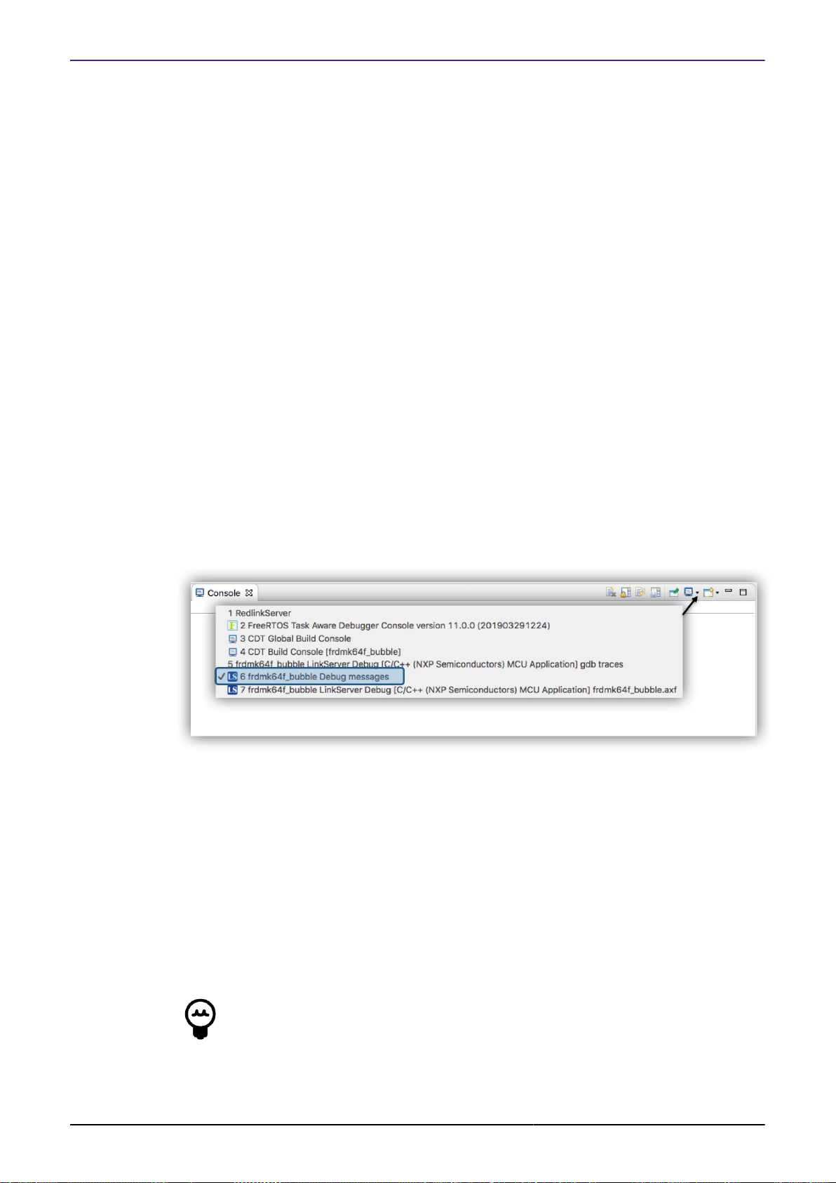
NXP Semiconductors MCUXpresso IDE User Guide
Reset Script a Reset Script overrides the default debug reset behaviour. Reset Scripts are
less commonly required than Connect Scripts but can be used to work around issues where
a standard Reset may not allow debug operations to survive. If required, a Reset Script is
referenced within a LinkServer debug Launch Configuration.
On rare occasions it may be useful to add a Connect or Reset Script to a project, see Project
Sharing [39] for more information on how this can be done.
Preconnect Script a Preconnect Script is a little different. Such a scripts (if present) prepares
the target MCU for an initial debug connection that may/would otherwise fail. Preconnect Scripts
are not specified within a launch configuration, rather they are automatically invoked by the IDE
for a given target based on built in intelligence. However, their use can be disabled by a checkbox
within the project’s Launch Configuration. On rare occasions it may be useful to add a preconnect
script to a project – this can be done by placing a file called LS_preconnect.scp within the project’s
directory.
Note: In most circumstances, such scripts are supplied and referenced (via SDKs) automatically
so no user intervention or action is required.
10.5 LinkServer Troubleshooting
10.5.1 Debug Log
On occasion, it can be useful to explore the operations of a debug session in more detail. The
steps are logged into a console known as the Debug log. This log will be displayed when a Debug
operation begins, but by default, will be replaced by another view when execution starts. The
debug log is a standard log within the IDE’s Console view. To display this log, select the Console
and then click to view the various options (as below):
The debug log displays a large amount of information which can be useful in tracking down
issues.
In the example debug log below, you can see that an initial Connect Script file has been run.
Connect scripts are required for debugging certain parts and are automatically added to launch
configuration files by the IDE if required. Next, the hardware features of the MCU are captured
and displayed, this includes the number of breakpoints and watchpoints available along with
details of various hardware components indicating what debug features might be available, for
example Instruction Trace.
MCUXpresso IDE User Guide -
User Guide
Further down in this log you will see the selection of a Flash driver (FTFE_4K), the identification
of the part being debugged (in this case a K64), the programming progress and the speed of the
Flash programming operation (in this case over 95 KB/sec).
Tip
a line similar to flash variant ‘K 64 FTFE Generic 4K’ detected (1MB = 256*4K at
0x0) will be displayed for LinkServer Flash programming operations. The size of the
detected flash (in this example it is 1MB) and sector size (4KB) will be displayed here.
The sector size may be important since multiples of this size represent valid base
All information provided in this document is subject to legal disclaimers
Rev. 11.3.1 — 2 April, 2021
© 2021 NXP Semiconductors. All rights reserved.
84
Page 93

NXP Semiconductors MCUXpresso IDE User Guide
addresses for flash programming operations. For example, if the programming of
more than one image is required, the second image must begin on a 4KB boundary
beyond the end of any previously programmed image.
MCUXpresso IDE RedlinkMulti Driver v11.1 (Nov 21 2019 14:13:54 - crt_emu_cm_redlink build 204)
Found part description in XML file MK64F12_internal.xml
Reconnected to existing LinkServer process.
============= SCRIPT: kinetisconnect.scp =============
Kinetis Connect Script
Connecting to Probe Index = 1
This probe = 1
This TAP = 0
This core = 0
DpID = 2BA01477
Assert NRESET
Reset pin state: 00
Power up Debug
MDM-AP APID: 0x001C0000
MDM-AP System Reset/Hold Reset/Debug Request
MDM-AP Control: 0x0000001C
MDM-AP Status (Flash Ready) : 0x00000032
Part is not secured
MDM-AP Control: 0x00000014
Release NRESET
Reset pin state: 01
MDM-AP Control (Debug Request): 0x00000004
MDM-AP Status: 0x0001003A
MDM-AP Core Halted
============= END SCRIPT =============================
Probe Firmware: LPC-LINK2 CMSIS-DAP V5.361 (NXP Semiconductors)
Serial Number: IQCYI2IV
VID:PID: 1FC9:0090
USB Path: USB_1fc9_0090_314000_ff00
Using memory from core 0 after searching for a good core
debug interface type = Cortex-M3/4 (DAP DP ID 2BA01477) over SWD TAP 0
processor type = Cortex-M4 (CPU ID 00000C24) on DAP AP 0
number of h/w breakpoints = 6
number of flash patches = 2
number of h/w watchpoints = 4
Probe(0): Connected&Reset. DpID: 2BA01477. CpuID: 00000C24. Info: <None>
Debug protocol: SWD. RTCK: Disabled. Vector catch: Disabled.
Content of CoreSight Debug ROM(s):
RBASE E00FF000: CID B105100D PID 04000BB4C4 ROM (type 0x1)
ROM 1 E000E000: CID B105E00D PID 04000BB00C Gen SCS (type 0x0)
ROM 1 E0001000: CID B105E00D PID 04003BB002 Gen DWT (type 0x0)
ROM 1 E0002000: CID B105E00D PID 04002BB003 Gen FPB (type 0x0)
ROM 1 E0000000: CID B105E00D PID 04003BB001 Gen ITM (type 0x0)
ROM 1 E0040000: CID B105900D PID 04000BB9A1 CSt TPIU type 0x11 Trace Sink - TPIU
ROM 1 E0041000: CID B105900D PID 04000BB925 CSt ETM type 0x13 Trace Source - Core
ROM 1 E0042000: CID B105900D PID 04003BB907 CSt ETB type 0x21 Trace Sink - ETB
ROM 1 E0043000: CID B105900D PID 04001BB908 CSt CSTF type 0x12 Trace Link - Trace funnel/router
NXP: MK64FN1M0xxx12
DAP stride is 4096 bytes (1024 words)
Inspected v.2 On chip Kinetis Flash memory module FTFE_4K.cfx
Image 'Kinetis SemiGeneric Nov 7 2019 19:12:49'
Opening flash driver FTFE_4K.cfx
Sending VECTRESET to run flash driver
Flash variant 'K 64 FTFE Generic 4K' detected (1MB = 256*4K at 0x0)
MCUXpresso IDE User Guide -
User Guide
All information provided in this document is subject to legal disclaimers
Rev. 11.3.1 — 2 April, 2021
© 2021 NXP Semiconductors. All rights reserved.
85
Page 94

NXP Semiconductors MCUXpresso IDE User Guide
Closing flash driver FTFE_4K.cfx
Connected: was_reset=true. was_stopped=true
Awaiting telnet connection to port 3330 ...
GDB nonstop mode enabled
Opening flash driver FTFE_4K.cfx (already resident)
Sending VECTRESET to run flash driver
Flash variant 'K 64 FTFE Generic 4K' detected (1MB = 256*4K at 0x0)
Writing 26880 bytes to address 0x00000000 in Flash
00001000 done 15% (4096 out of 26880)
00002000 done 30% (8192 out of 26880)
00003000 done 45% (12288 out of 26880)
00004000 done 60% (16384 out of 26880)
00005000 done 76% (20480 out of 26880)
00006000 done 91% (24576 out of 26880)
00007000 done 100% (28672 out of 26880)
Sectors written: 7, unchanged: 0, total: 7
Erased/Wrote sector 0-6 with 26880 bytes in 276msec
Closing flash driver FTFE_4K.cfx
Flash Write Done
Flash Program Summary: 26880 bytes in 0.28 seconds (95.11 KB/sec)
Starting execution using system reset and halt target
Stopped (Was Reset) [Reset from Unknown]
Stopped: Breakpoint #1
10.5.2 Flash Programming
Most debug sessions begin with the programming of Flash, followed by a reset of the MCU. Note:
If flash programming should fail then the debug operation will be aborted.
Starting with MCUXpresso IDE version 11.1.0 – most LinkServer flash drivers now implement a
Verify Same operation (via a flash hashing mechanism) for any flash sector that are unchanged
from previous debug operations.
Below is a fragment of a debug log repeating the previous debug operation. The log reports the
Sectors that were unchanged from the previous operation and the resultant overall speed of the
flash operation – in this case the equivalent of a programming speed of 937 KB/sec.
...
Opening flash driver FTFE_4K.cfx (already resident)
Sending VECTRESET to run flash driver
Flash variant 'K 64 FTFE Generic 4K' detected (1MB = 256*4K at 0x0)
Writing 26880 bytes to address 0x00000000 in Flash
Sectors written: 0, unchanged: 7, total: 7
Erased/Wrote sector 0-6 with 26880 bytes in 28msec
Closing flash driver FTFE_4K.cfx
Flash Write Done
Flash Program Summary: 26880 bytes in 0.03 seconds (937.50 KB/sec)
Starting execution using system reset and halt target
Stopped (Was Reset) [Reset from Unknown]
Stopped: Breakpoint #1
MCUXpresso IDE User Guide -
User Guide
Note in the unlikely event of this feature causing problems, it can be disabled from a project
LinkServer Launch Configuration by unchecking the Enable Flash hashing option. Alternatively,
the feature can be disabled as a workspace preference via MCUXpresso IDE -> Debug Options
-> LinkServer Options -> Enable flash hashing
Below is a brief discussion of the most common low level flash operations:
All information provided in this document is subject to legal disclaimers
Rev. 11.3.1 — 2 April, 2021
© 2021 NXP Semiconductors. All rights reserved.
86
Page 95

NXP Semiconductors MCUXpresso IDE User Guide
1. Sector Erase: internally Flash devices are divided into a number of sectors (or blocks), where
a sector is the smallest size of Flash that can be erased in a single operation. A sector will be
larger than a page (see below). Sectors are usually the same size for the whole Flash device,
however this is not always the case. A sector base address will be aligned on a boundary that
is a multiple of its size. A sector erase is usually the first step in a flash programming sequence.
2. Page Program: internally Flash devices are divided into a number of pages, where a page is
the smallest size that can be programmed in a single operation. A page will be smaller than a
sector. A page base addresses will be aligned on a boundary that is a multiple of its size.
3. Mass Erase: a mass erase will reset all the bytes in Flash (usually to 0xff). Such an
operation may clear any internal low level structuring such as protection of Flash areas (from
programming).
The programming of an image (or data) comprises repeated operations of sector erase followed
by a set of program page operations; until the sector is fully programmed or there is no more
data to program.
One of the common problems when programming Kinetis parts relates to their use of Flash
configuration block at offset 0x400. For more information please see: Kinetis MCUs Flash
Configuration Block [188] . Flash sector sizes on Kinetis MCUs range from less than 1KB to
8KB, therefore the first Sector Erase performed may clear the value of this block to all 0xFFs,
if this is not followed by a successful program operation and the part is reset, then it will likely
report as ‘Secured’ and subsequent debugging will not be possible until the part is recovered.
Such an event can occur if a debug operation is accidentally performed to the ‘wrong board’ so
a wrong Flash programmer is invoked.
Note: LinkServer mass erase operations will restore this Flash configuration block automatically
for Kinetis parts. However, if a Kinetis device is mass erased by sector, this mechanism will be
bypassed, therefore this operation should not be performed to Kinetis parts!
Should you need to recover a ‘locked’ part please see the section LinkServer GUI Flash
Tool [140]
10.5.3 LinkServer executables
LinkServer debug operations rely on 3 main debug executables.
• arm-none-eabi-gdb – this is a version of GDB built to target ARM based MCUs
• crt_emu_cm_redlink – this executable (known as the debug stub) communicates with GDB
and passes low level commands to the LinkServer executable (also known as Redlink server)
• redlinkserv – this is the LinkServer executable and takes stub operations and communicates
directly with the ARM Cortex debug hardware via the debug probe.
• rltool - utility sometime used by the IDE to directly communicate with redlinkserv
If a debug operation fails, or a crash occurs, it is possible that one or more of these processes
may fail to shut down correctly. Therefore, if the IDE has no active debug connection but is
experiencing problems making a new debug connection, ensure that none of these executables
10.6 PEmicro Debug Connections
MCUXpresso IDE User Guide -
User Guide
is running. To simplify this process an IDE button is provided to kill all low level debug
executables (for all debug solutions). Therefore should a debug operation fail or a crash occur,
simply click this button before starting a new debug operation.
PEmicro software and drivers are automatically installed when MCUXpresso IDE installs. There
is no need to perform any additional setup to use PEmicro debug connections.
Currently we have tested using:
All information provided in this document is subject to legal disclaimers
Rev. 11.3.1 — 2 April, 2021
© 2021 NXP Semiconductors. All rights reserved.
87
Page 96

NXP Semiconductors MCUXpresso IDE User Guide
• Multilink Universal (FX)
• Cyclone Universal (FX) (USB and Ethernet)
• PEmicro firmware installed into on-board OpenSDA debug probe hardware (as shipped by
default on certain Kinetis FRDM and TWR boards)
Note: Some Kinetis boards ship with OpenSDA supporting PEmicro VCOM but with no debug
support. To update this firmware visit the OpenSDA Firmware Update pages linked at: Help ->
Additional Resources -> OpenSDA Firmware Updates
10.7 PEmicro Debug Operation
The process to debug via a PEmicro compatible debug probe is exactly the same as for a native
LinkServer (CMSIS-DAP) compatible debug probe. Simply select the project via the ‘Project
Explorer’ view then click Debug from the Quickstart panel and select the PEmicro debug probe
from the Probe Discovery Dialogue.
If more than one debug probe is presented, select the required probe and then click ‘OK’ to start
the debug session. At this point, the projects launch configuration files will be created. Note:
PEmicro Launch configuration files will contain the string ‘PE’.
MCUXpresso IDE stores the probe information, along with its serial number in the projects launch
configuration. This mechanism is used to match any attached probe when an existing launcher
configuration already exits.
To simplify debug operations, MCUXpresso IDE will automatically start PEmicro’s GDB Server
and select and dynamically assign the various ports needed as required. This means that multiple
PEmicro debug connections can be started, terminated, restarted etc. all without the need for
any user connection configuration. These options can be controlled if required by editing the
PEmicro launch configuration file.
For more information see Common Debugging Operations [104]
Note: If the project already had a PEmicro launch configuration, this will be selected and used.
If they are no longer appropriate for the intended connection, simply delete the files and allow
new launch configuration files to be created.
Important Note: Low level debug operations via PEmicro debug probes are supported by
PEmicro software. This includes, Part Support handling, Flash Programming, and many other
features. If problems are encountered, PEmicro maintain a range of support forums at https://
www.pemicro.com/forums/
Note: If a debug operation fails, or a crash occurs, it is possible that one or more debug processes
may fail to shut down correctly. Therefore, if the IDE has no active debug connection but is
experiencing problems making a new debug connection, ensure that none of these executables
is running. To simplify this process an IDE button is provided to kill all low level debug
executables (for all debug solutions). Therefore should a debug operation fail or a crash occur,
simply click this button before starting a new debug operation.
10.7.1 PEmicro Differences from LinkServer Debug
MCUXpresso IDE User Guide -
User Guide
MCUXpresso IDE core technology is intended to provide a seamless environment for code
development and debug.
When used with PEmicro debug probes, the debug environment is provided by the PEmicro
debug server. This debug server does not 100% match the features provided by native
LinkServer connections. However basic debug operations will be very similar to LinkServer
debug.
All information provided in this document is subject to legal disclaimers
Rev. 11.3.1 — 2 April, 2021
© 2021 NXP Semiconductors. All rights reserved.
88
Page 97

NXP Semiconductors MCUXpresso IDE User Guide
For a description of some common debugging operations using supported debug probes see
Common Debugging Operations [104]
Note: LinkServer advanced features such as Power Measurement will not be available via a
PEmicro debug connection. However, additional functionality maybe available using PEmicro
supplied plugins.
10.7.2 PEmicro Software Updates
PEmicro support within MCUXpresso IDE is via an Eclipse plugin. The PEmicro update site is
automatically added to the list of Available Software Update sites.
To check whether an update is available, please select:
Help -> Check for Updates
Any available updates from PEmicro will then be listed for selection and installation.
Note: PEmicro may provide news and additional information on their website, for details see
https://www.pemicro.com
10.8 SEGGER Debug Connections
SEGGER J-Link software and documentation pack is installed automatically with the
MCUXpresso IDE Installation for each host platform. No user setup is required to use the
SEGGER debug solution within MCUXpresso IDE.
Currently we have tested using:
• J-Link debug probes (USB and Ethernet)
• J-Link firmware installed into on-board OpenSDA debug probe hardware (as shipped by default
on certain Kinetis FRDM and TWR boards)
• J-Link firmware installed onto LPC-Link2 debug hardware and LPCXpresso V2/V3 boards
• for details see https://www.segger.com/lpc-link-2.html
• also for firmware programming see http://www.nxp.com/LPCSCRYPT
10.8.1 SEGGER software installation
Unlike other debug solutions supplied with MCUXpresso IDE, the SEGGER software installation
is not integrated into the IDE installation, rather it is a separate SEGGER J-Link installation on
your host.
The installation location will be similar to:
MCUXpresso IDE User Guide -
User Guide
On Windows: C:/Program Files (x86)/SEGGER/JLink
On Mac: /Applications/SEGGER/JLink
On Linux: /opt/SEGGER/JLink
MCUXpressoIDE automatically locates the required executable and it is remembered as a
Workspace preference. This can be viewed or edited within the MCUXpresso IDE preferences
as below.
All information provided in this document is subject to legal disclaimers
Rev. 11.3.1 — 2 April, 2021
© 2021 NXP Semiconductors. All rights reserved.
89
Page 98

NXP Semiconductors MCUXpresso IDE User Guide
Figure 10.7. Segger Preferences
Note: this preference also provides the option to enable scanning for SEGGER IP probes (when
a probe discovery operation is performed). By default, this option is disabled.
From time to time, SEGGER may release later versions of their software, which the user could
choose to manually install. For details see https://www.segger.com/downloads/jlink
MCUXpresso IDE will continue to use the SEGGER installation path as referenced in a project’s
workspace unless the required executable cannot be found (for example, the referenced
installation has been deleted). If this occurs:
1. The IDE will automatically search for the latest installation it can find. If this is successful, the
Workspace preference will automatically be updated
2. If a SEGGER installation cannot be found, the user will be prompted to locate an installation
To force a particular workspace to update to use a newer installation location simply click the
Restore Default button.
To permanently select a particular SEGGER installation version, the location of the SEGGER
GDB Server can be stored in an environment variable.
For example, under Windows you could set:
MCUX_SEGGER_SERVER="C:/Program Files (x86)/SEGGER/JLink_V630k/jLinkGDBServerCL.exe"
MCUXpresso IDE User Guide -
User Guide
This location will then be used, overriding any workspace preference that maybe set.
SEGGER software un-installation
If MCUXpresso IDE is uninstalled, it will not remove the SEGGER J-Link installation. If this is
required, then the user must manually uninstall the SEGGER J-Link tools.
Note: If for any reason MCUXpresso IDE cannot locate the SEGGER J-Link software, then the
IDE will prompt the user to either manually locate an installation or disable the further use of the
SEGGER debug solution.
All information provided in this document is subject to legal disclaimers
© 2021 NXP Semiconductors. All rights reserved.
Rev. 11.3.1 — 2 April, 2021
90
Page 99

NXP Semiconductors MCUXpresso IDE User Guide
10.9 SEGGER Debug Operation
The process to debug via a J-Link compatible debug probe is exactly the same as for a native
LinkServer (CMSIS-DAP) compatible debug probe. Simply select the project via the ‘Project
Explorer’ view then click Debug from the Quickstart Panel and select the SEGGER Probe from
the Probe Discovery Dialogue.
If more than one debug probe is presented, select the required probe and then click ‘OK’ to start
the debug session. At this point, the projects launch configuration files will be created. Note:
SEGGER Launch configuration files will contain the string ‘JLink’.
To simplify debug operations, MCUXpresso IDE will automatically start SEGGER’s GDB Server
and select and dynamically assign the various ports needed as required. This means that multiple
SEGGER debug connections can be started, terminated, restarted etc. all without the need for
any user connection configuration. These options can be controlled if required by editing the
SEGGER launch configuration file.
In MCUXpresso IDE, SEGGER Debug operations default to using the SWD Target Interface.
When debugging certain multicore parts such as the LPC43xx Series, the JTAG Target Interface
must be used to access the internal Slave MCUs. To select JTAG as the Target Interface, simply
edit the SEGGER launch configuration file and select JTAG.
For more information see Common Debugging Operations [104]
Note: If the project already had a SEGGER launch configuration, this will be selected and used.
If an existing launch configuration file is no longer appropriate for the intended connection, simply
delete the files and allow new launch configuration files to be created.
Tip
If Reset before running is set in the Launch configuration, then a default intelligent
reset will be used. This reset automatically supports running from Flash or RAM.
A specific reset type can optionally be set from the free form text field if required,
please consult SEGGER’s documentation for available reset types.
Important Note: Low level debug operations via SEGGER debug probes are supported by
SEGGER software. This includes, Part Support handling, Flash Programming, and many other
features. If problems are encountered, SEGGER’s provide a range of support forums at http://
forum.segger.com/
10.9.1 SEGGER Differences from LinkServer Debug
MCUXpresso IDE core technology is intended to provide a seamless environment for code
development and debug. When used with SEGGER debug probes, the debug environment is
provided by the SEGGER debug server. This debug server does not 100% match the features
provided by native LinkServer connections. However basic debug operations will be very similar
to LinkServer debug.
For a description of some common debugging operations using supported debug probes see
Common Debugging Operations [104]
Note: LinkServer features such as Power Measurement will not be available via a SEGGER
debug connection. However, additional functionality maybe available using external SEGGER
supplied applications.
10.10 SEGGER Troubleshooting
When a debug operation to a SEGGER debug probe is performed, the SEGGER GDB server
is called with a set of arguments provided by the launch configuration file. The command and
resulting output are logged within the IDE SEGGER Debug Console. The console can be viewed
as below:
MCUXpresso IDE User Guide -
User Guide
All information provided in this document is subject to legal disclaimers
Rev. 11.3.1 — 2 April, 2021
© 2021 NXP Semiconductors. All rights reserved.
91
Page 100

NXP Semiconductors MCUXpresso IDE User Guide
Figure 10.8. Segger Server
The command can be copied and called independently of the IDE to start a debug session and
explore connection issues.
Below is the shortened output of a successful debug session to a Kinetis K64 Board.
[02-4-2019 02:24:50] Executing Server: /Applications/SEGGER/JLink_V644d/JLinkGDBServerCLExe /
-nosilent -swoport 2332 -select USB=600102843 -telnetport 2333 -singlerun -endian little /
-noir -speed auto -port 2331 -vd -device MK64FN1M0xxx12 -if SWD -halt -reportuseraction
SEGGER J-Link GDB Server V6.44d Command Line Version
JLinkARM.dll V6.44d (DLL compiled Mar 27 2019 17:10:37)
Command line: -nosilent -swoport 2332 -select USB=600102843 -telnetport 2333 -singlerun /
-endian little -noir -speed auto -port 2331 -vd -device MK64FN1M0xxx12 -if SWD -halt/
-reportuseraction
-----GDB Server start settings----GDBInit file: none
GDB Server Listening port: 2331
SWO raw output listening port: 2332
Terminal I/O port: 2333
Accept remote connection: yes
Generate logfile: off
Verify download: on
Init regs on start: off
Silent mode: off
Single run mode: on
Target connection timeout: 0 ms
------J-Link related settings-----J-Link Host interface: USB
J-Link script: none
J-Link settings file: none
------Target related settings-----Target device: MK64FN1M0xxx12
Target interface: SWD
Target interface speed: auto
Target endian: little
MCUXpresso IDE User Guide -
User Guide
Connecting to J-Link...
J-Link is connected.
Device "MK64FN1M0XXX12" selected.
Firmware: J-Link V10 compiled Mar 21 2019 15:43:57
Hardware: V10.10
S/N: 600102843
All information provided in this document is subject to legal disclaimers
Rev. 11.3.1 — 2 April, 2021
© 2021 NXP Semiconductors. All rights reserved.
92
 Loading...