

Page 1

NXP Semiconductors Document identifier: IEC60730BLPC55SXXEUG
User's Guide Rev. 0, 12/2020
LPC55Sxx Safety Example
Page 2

NXP Semiconductors
Contents
Chapter 1 IEC60730B Safety library example user's guide...................................3
Chapter 2 Hardware settings................................................................................. 4
Chapter 3 File structure......................................................................................... 7
Chapter 4 Example application.............................................................................. 9
Chapter 5 Running example................................................................................ 12
Chapter 6 IEC60730B tests................................................................................. 15
LPC55Sxx Safety Example, Rev. 0, 12/2020
User's Guide 2 / 19
Page 3

NXP Semiconductors
Chapter 1
IEC60730B Safety library example user's guide
For easier development of the IEC60730B application, the library also provides the example code. This example is distributed
through the MCUXpresso SDK website. This example user's guide describes how to set the hardware correctly and how to use
the example code with the IEC60730B Safety library.
The library user's guide is the main documentation for IEC60730B. It is also part this package and accessible at
www.nxp.com/IEC60730.
LPC55Sxx Safety Example, Rev. 0, 12/2020
User's Guide 3 / 19
Page 4

NXP Semiconductors
Chapter 2
Hardware settings
This chapter describes how to set up the hardware of the evaulation board. The MCU peripherals' setup is described later on.
The IEC60730B library example for the LPC55Sxx family supports the following development boards:
• LPCxpresso55S69
• LPCxpresso55S28
To run the IEC60730B example application, it is neccessary to make some hardware settings. For the default configuration of your
development board, see the corresponding board's user manual at www.nxp.com.
2.1 LPCXpresso55S69
To use the on-board debugger and power the board via USB, make sure that jumper J3 is set to "Loc". Then connect the USB to
connector P6.
NOTE
If downloading to device does not work, press and hold the S1 button during download.
See the Hardware User’s Guide for more options.
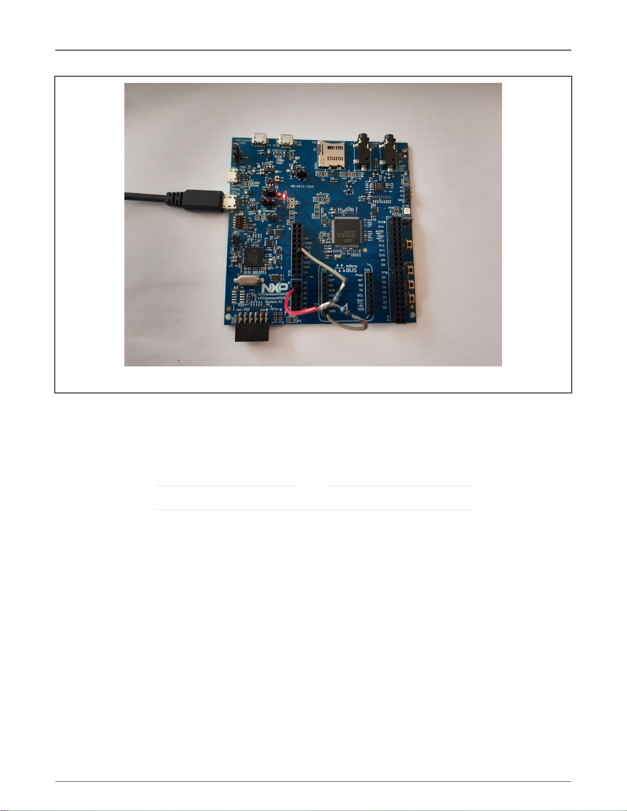
The ADC module on LPCXpresso55S69 does not allow to connect the Bandgap internally to the ADC input. It is necessary to
connect these signals (for the Analog I/O test) as follows:
• VrefH 3.3 V is connected internally.
• VrefL - GND is connected internally.
• Bandgap - connect a custom reference (for example 1.65 V) to PIO0_23 (P19-4). The expected value of the custom bandgap
can be set in the
safety_config.h
file (#define ADC_EXTERNAL_PIN_LEVEL 1.65).
LPC55Sxx Safety Example, Rev. 0, 12/2020
User's Guide 4 / 19
Page 5
NXP Semiconductors
Hardware settings
Figure 1. Hardware connection of LPCXpresso55S69
The test voltage of 1.65 V is provided by a resistor voltage divider from the VCC (3.3 V).
2.2 LPCXpresso55S28
To use the on-board debugger and power the board via USB, make sure that jumper J3 is set to "Loc". Then connect the USB to
connector P6.
NOTE
If downloading to device does not work, press and hold the S1 button during download.
See the
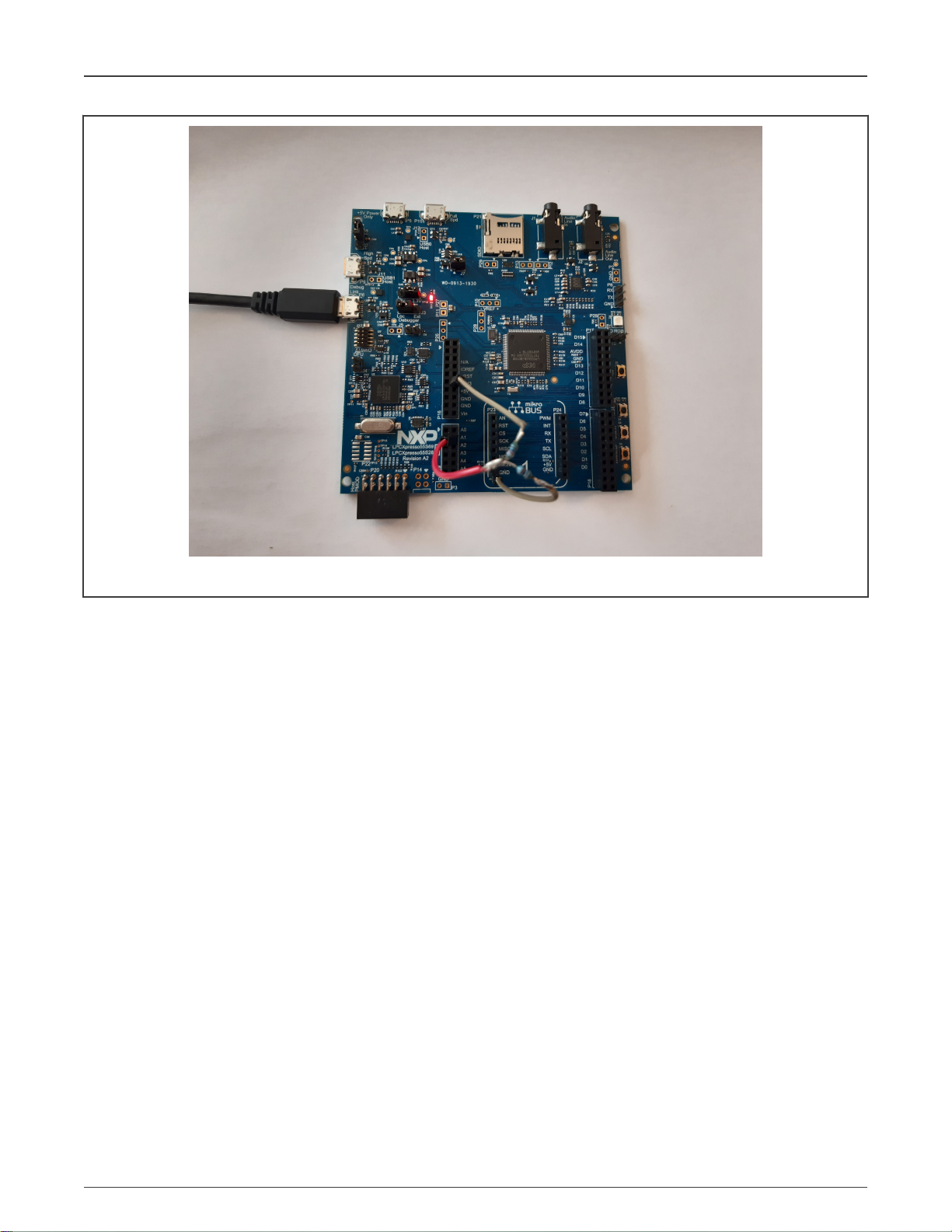
The ADC module on LPCXpresso55S28 does not allow to connect the Bandgap internally to the ADC input. Thus, it is necessary
to connect these signals (for the Analog I/O test) as follows:
LPCXpresso55S69/55S28 Development Boards User Manual
(document UM11158) for more details.
• VrefH 3.3 V is connected internally.
• VrefL - GND is connected internally.
• Bandgap - connect a custom reference (for example 1.65 V) to PIO0_23 (P19-4). The expected value of the custom bandgap
can be set in the
safety_config.h
file (#define ADC_EXTERNAL_PIN_LEVEL 1.65).
LPC55Sxx Safety Example, Rev. 0, 12/2020
User's Guide 5 / 19
Page 6
NXP Semiconductors
Hardware settings
Figure 2. Hardware connection of LPCXpresso55S28
The test voltage of 1.65 V is provided by a resistor voltage divider from the VCC (3.3 V).
LPC55Sxx Safety Example, Rev. 0, 12/2020
User's Guide 6 / 19
Page 7

NXP Semiconductors
Chapter 3
File structure
Safety is only a small part of the whole SDK package for your device. The IEC60730 library and examples are located in the
middleware and in the board folders. The IEC60730 library is independent of the SDK and can be used stand-alone.
3.1 Library source files location
The library source files are in the
The folder has the following structure:
middleware/safety_iec60730b/safety/v4_1
folder in the SDK package.
Where:
• common_test contains the source files for the “peripheral” test – this is a common cross core. These tests are compiled to
library
libIEC60730B_<core>_COM_<compiler>_<version>.a
• compiler - compiler support files.
• core_test contains the source files for the core-dependent test. These tests are compiled to library
libIEC60730B_<core>_<compiler>_<version>.a
•
iec60730b.h
•
iec60730b_types.h
The folder also contains binary
for details).
User's Guide 7 / 19
is the main library header file.
is the header file with the necessary defines for the library.
*.lib
files which are compiled for the IAR, Keil, and MCUXpresso IDEs (see the release notes
LPC55Sxx Safety Example, Rev. 0, 12/2020
.
.
Page 8

NXP Semiconductors
File structure
3.2 Example of library handling code
The library-handling code and the example aplication are separate from the library file. The example source files and other SDK
examples are at this path:
boards/<your board>/demo_apps/safety_iec60730b/
The safety example code is shown in Figure 3.
Figure 3. Example of project structure in example folder
This folder contains the example source file and three folders for the IDE project file:
•
iar
•
mcux
•
mdk
The following files are generated by the MCUXpresso configuration tool:
•
clock_config.h
•
clock_config.c
•
pin_mux.c
•
pin_mux.h
Other files are used only for safety examples and their contents are described in the next chapter.
LPC55Sxx Safety Example, Rev. 0, 12/2020
User's Guide 8 / 19
Page 9
NXP Semiconductors
Chapter 4
Example application
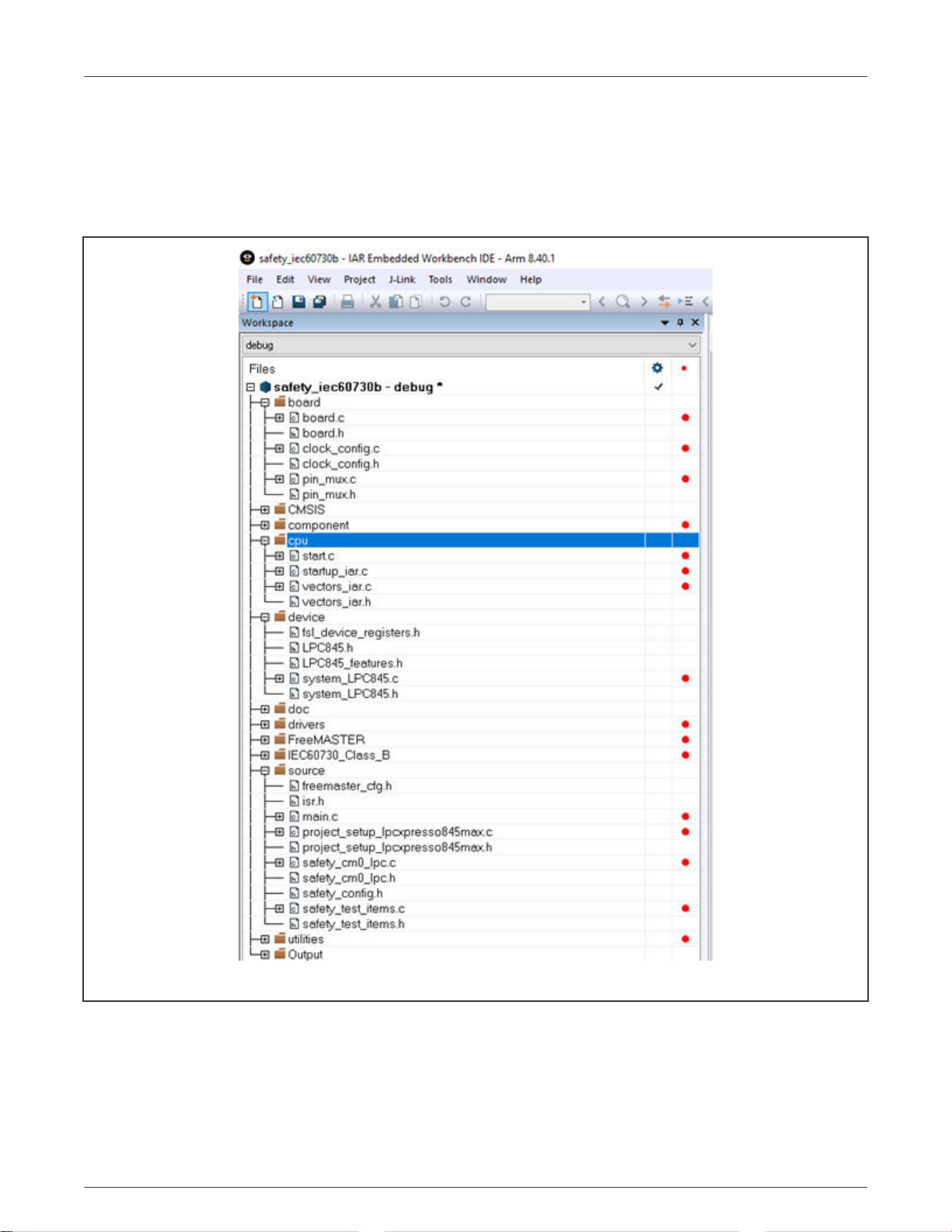
The structure of the example is common in all supported IDEs (IAR, Keil, MCUXpresso).
Figure 4. IAR example application structure
The project contains the CMSIS, SDK, library, and safety example-related folders.
The safety-related folders are the following:
•
Board
– this folder contains the files related to the board used (
•
CPU
– this folder contains the startup code and vectors table.
•
IEC60730_Class_B
User's Guide 9 / 19
– files for the IEC60730B Safety library.
LPC55Sxx Safety Example, Rev. 0, 12/2020
clock_config.h, pin_config.h, board.h
, and so on).
Page 10

NXP Semiconductors
•
Source
– source file for the safety example (see the next explanation).
The example of project hiearchy is shown in Figure 5.
Example application
Figure 5. Example of project hiearchy
Figure 5 shows that the functions in the
located in the
The main example application header file
safety_test_items.c
setup functions (clock, port, UART, and so on). The safety_cm33_lpc.c file contains the handling function for safety routines from
the IEC60730B library and also the test-initialization function for safety.
safety_cm33_lpc.c
file declares the structures for the DIO (or TSI) safety test. The
project_setup.c
file and also called from the
safety_config.h
file are called from the
contains all definitions for running the safety test in examples. The
main.c
file.
main.c
file. The library-handling functions are
project_setup_<your_board>.c
file contains the
4.1 How to open the project
IAR IDE
Open the project file located at
Arm Keil IDE
Open the project file located at
MCUXpresso IDE
Firstly, drag and drop the
Secondly, import the SDK example (safety_iec60730b).
boards/<your_board>/demo_apps/safety_iec60730b/iar/safety_iec60730b.eww
boards/<your_board>/demo_apps/safety_iec60730b/mdk/safety_iec60730b.uvprojx
<name_of_the_package>.zip
package into the MCUXpresso IDE (into the "Installed SDKs" tab).
.
.
LPC55Sxx Safety Example, Rev. 0, 12/2020
User's Guide 10 / 19
Page 11

NXP Semiconductors
Example application
If you are not familiar with the MCUXpresso IDE yet, see
an example application" section).
docs/Getting Started with MCUXpresso SDK for <your_board>.pdf
("Build
4.2 Example settings - safety_config.h
The main example settings header file is
The "switch macros", which enable the user to turn off calling of the safety test, are defined in the beginning. When starting, turn
off the FLASH test and the WDOG test. On LPC devices, turn off also the Clock test.
/* This macro enables infinity while loop in SafetyErrorHandling() function */
#define SAFETY_ERROR_ACTION 1
/* TEST SWITCHES - for debugging it is better to turn the flash test and watchdog OFF */
#define ADC_TEST_ENABLED 1
#define CLOCK_TEST_ENABLED 1
#define DIO_TEST_ENABLED 1
#define FLASH_TEST_ENABLED 1
#define PC_TEST_ENABLED 1
#define WATCHDOG_ENABLED 1
#define FMSTR_SERIAL_ENABLE 1
safety_config.h
. The neccessary macros for the safety example are defined in this file.
Other defines are used to configure the safety test as a parameter to a function or to fill structures.
4.3 safety_test_items.c file
The
safety_test_items.c
The file contains the
dio_safety_test_items[]
fs_dio_test_lpc_t dio_safety_test_item_0 = /* P1_8 */
{
.iocon_mode_shift = IOCON_PIO_MODE_SHIFT, /*Device depend*/
.pPort_byte = (uint8_t *)&(GPIO->B[1][8]), /*adress of byte register in GPIO*/
.pPort_dir = (uint32_t *)&(GPIO->DIR[1]), /* asress of dir1 register*/
.pPort_Iocon = (uint32_t *)&(IOCON->PIO[1][8]), /* Adress of concrete IOCON register*/
.pinNum = 8, /*Position in DIR registor*/ .gpio_clkc_shift = SYSCON_AHBCLKCTRL0_GPIO1_SHIFT
};
/* NULL terminated array of pointers to dio_test_t items for safety DIO test */
fs_dio_test_lpc_t *dio_safety_test_items[] = { &dio_safety_test_item_0, &dio_safety_test_item_1, NULL };
and .h files are the configuration files for the DIO test.
fs_dio_test_<platform>_t
array, which is used in the example application.
list of structures. The pointers to these structures are collected in the
4.4 Source file - safety_safety_cm33_lpc.c/.h
The
safety_cm33_lpc.c
detection. If a safety error ocurrs, the
User's Guide 11 / 19
source file and the corresponding
SafetyErrorHandling()
LPC55Sxx Safety Example, Rev. 0, 12/2020
*.h
file contain a library handling function. Each function contains a
function is called.
Page 12

NXP Semiconductors
Chapter 5
Running example
For the first run of the example on your hardware, it is recomended to turn off Flash, WDOG, Clock, AIO, and DIO test. In the next
step, turn on step by step.
When the WDOG is turned off and a safety error happens, the example stays in an endless loop.
5.1 FreeMASTER monitoring
FreeMASTER is used as the external PC tool for real-time monitoring. FreeMASTER is also implemented in the IEC60730B safety
examples. For simplicity reasons, the MAP file is the source of the variable address. Before connecting FreeMASTER to your
application, make sure that the application is running.
Running FreeMASTER:
Download and install FreeMASTER from www.nxp.com/freemaster.
The example project is in the
Check the project settings for your application:
• Open "Project->Options ->MAP Files". It must point to your output files.
IAR IDE and ARM Keil IDE
Navigate to the
MCUXpresso IDE
Navigate to the
boards/<your_board>/demo_apps/safety_iec60730b/<compiler>/<debug or release>/*.out
<workspace>/<project_name>/<Debug or Release>/<project_name>.axf
safety.pmp
file. Open it.
file.
file.
Figure 6. Example of setting MAP files for FRDM-KV11 board
• Open "Project ->Options ->Comm" and select a correct RS-232 connection and speed. The connection speed is in the
safety_config.h
User's Guide 12 / 19
file's "SERIAL_BAUD_RATE" macros. By default, this speed is set to 9600 bd.
LPC55Sxx Safety Example, Rev. 0, 12/2020
Page 13

NXP Semiconductors
Running example
Figure 7. Setting UART speed
Now you can connect to the development board by pressing "CTRL+G" or clicking the "GO" button:
LPC55Sxx Safety Example, Rev. 0, 12/2020
User's Guide 13 / 19
Page 14

NXP Semiconductors
Running example
Figure 8. Safety example FMSTR application
Usually, the AIO test is a number of results oscillating between 0x0 and 0x704 (test passed and test in progress).
LPC55Sxx Safety Example, Rev. 0, 12/2020
User's Guide 14 / 19
Page 15

NXP Semiconductors
Chapter 6
IEC60730B tests
The library contains the following tests:
• Analog I/O test
• Clock test
• CPU register test
• Digital I/O test
• Invariable memory (flash) test
• Variable memory (RAM) test
• Program counter test
• Stack test
• Watchdog test
• Touch-sensing peripheral TSIv5 test
The following chapters describe each test with focus on the example application (debugging).
6.1 AIO test
The analog IO test procedure performs the plausibility check of the digital IO interface of the processor. The analog IO test can
be performed once after the MCU reset and also during runtime.
There are three values tested in the application:
• VrefH
• VrefL
• Bandgap
Ensure that the ADC peripheral is set up correctly before calling the AIO test. In some cases, it is necessary to connect this signal
externally (by a wire) to the corresponding pin. The test is perfomed in a sequence, as defined in the
/* ADC test */
...
...
{\
{(uint32_t)ADC_MIN_LIMIT(0), (uint32_t)ADC_MAX_LIMIT(60)}, \
{(uint32_t)ADC_MIN_LIMIT(ADC_MAX), (uint32_t)ADC_MAX_LIMIT(ADC_MAX)},\
{(uint32_t)ADC_MIN_LIMIT(ADC_BANDGAP_LEVEL_RAW),
(uint32_t)ADC_MAX_LIMIT(ADC_BANDGAP_LEVEL_RAW)}\ }
safety_config.h
file:
#define FS_CFG_AIO_CHANNELS_INIT {6, 5, 4} /* ADC Channels for V_refl, V_refh, bandgap */
An example of the setting is shown above. The
first, with the limits corresponding to VrefL (GND). Channel 5 is tested next, with the limits of VrefH (VCC). Channel 4 is tested
next, with the limits for the bandgap.
User's Guide 15 / 19
"FS_CFG_AIO_CHANNELS_INIT"
LPC55Sxx Safety Example, Rev. 0, 12/2020
macro defines that the ADC channel 6 is tested
Page 16

NXP Semiconductors
IEC60730B tests
6.2 Clock test
The clock test procedure tests the oscilator frequency for the CPU core in the wrong frequency condition.
NOTE
The default clock setting from the SDK library is used in the example. For a real application, ensure that the
reference clock source is not dependent on the primary (tested) clock.
6.3 CPU register
The CPU register test procedure tests all CPU registers for the stuck-at condition (except for the program counter register). The
program counter test is implemented as a stand-alone safety routine.
Some tests stay in an endless loop in case of an error, others return a corresponding error message.
6.4 DIO test
The Digital Input/Output (DIO) test procedure performs the plausibility check of the processor's digital IO interface.
NOTE
Make sure that the time between the "set" and "get" functions is sufficient for the GPIO peripheral speed.
6.5 Invariable memory test
The invariable (Flash) memory test provides a CRC check of a dedicated part of memory. This test is turned off by default in the
safety_config.h
The test consists of the following two parts:
• Post-build CRC calculation of the dedicated memory.
• Runtime CRC calculation and comparison with the post-build result.
The post-build calculation is different for each IDE:
In the IAR IDE, the CRC is calculated by the IDE directly using the linker (see Options->Build Action). The Flash test is fully
integrated to the example project in the IAR IDE. It is necessary only to turn this test on in the
In the Arm Keil IDE, it is necessary to use a third-party tool (Srecord):
• Srecord and all necessary settings are added to the presented example by default.
• Turn on the Flash test in the
• The final post-processed image is downloaded to the ROM memory using the "Download" button.
• For more information on using Srecord in Arm Keil IDE, see
AN12520).
In case of an issue, check the following settings:
• Check if the "Option -> User -> AfterBuild" tab contains the
-..\..\..\..\boards|<YOUR_BOARD>\demo_apps\safety_iec60730b\mdk\debug\safety_iec60730b.hex
-..\..\..\..\boards\<YOUR_BOARD\demo_apps\safety_iec60730b\mdk\debug\safety_iec60730b_crc.hex
-..\..\..\..\tools\srecord\srec_cat"
file.
safety_config.h
safety_config.h
file.
Calculating Post-Build CRC in Arm® Keil
®
(document
"..\..\..\..\..\middleware\safety_iec60730b\tools\crc\crc_hex.bat
path and if the checkbox is selected (it should be filled and checked by default).
file.
• Check if the "Option->Debug ->Initialization File" tab contains the "
common/debug.ini
In the MCUXpresso IDE:
• Srecord and all necessary settings are added to the presented example by default.
• Turn on the Flash test in the
User's Guide 16 / 19
" path.
safety_config.h
LPC55Sxx Safety Example, Rev. 0, 12/2020
file.
./../../../../middleware/safety_iec60730b/boards/
Page 17

NXP Semiconductors
IEC60730B tests
• Create the "debug configuration" for your debbuger.
• Open the "Debug Configurations" menu ("Run->Debug configuration") and select the "Startup" tab. In this tab, select
"Load Image -> Use File ->
<YOUR_BOARD>_safety_iec60730b_crc.hex
".
• This edited HEX file is located in the
<workspace>/<your_project>/Debug/<your_project>_crc.hex
folder.
Figure 9. Using output HEX file with calculated CRC in MCUXpresso IDE
In case of an issue, check also the following settings:
• Check if the post-build actions are set:
"arm-none-eabi-objcopy -v -O ihex "$
{BuildArtifactFileName}" "${BuildArtifactFileBaseName}.hex" ${ProjDirPath}/linker/crc_hex.bat -..\\\\${ConfigName}\
\frdmk22f_dev_safety_iec60730b.hex -..\\\\${ConfigName}\\frdmk22f_dev_safety_iec60730b_crc.hex -..\\safety_iec60730b\
\tools\\srec\\srec_cat"
When you debug your application with the Flash test turned on, be careful when using the breakpoint. The software
breakpoint usually changes the CRC result and causes a safety error.
. It should be filled by default.
NOTE
6.6 Variable memory test
The variable memory on the supported MCU is an on-chip RAM.
The RAM memory test is provided by the MarchC or MarchX tests.
The test copies a block of memory to the backup area defined by the linker. Be sure that the BLOCK_SIZE parameter is smaller
than the backup area defined by the linker.
NOTE
This test cannot be interupted.
LPC55Sxx Safety Example, Rev. 0, 12/2020
User's Guide 17 / 19
Page 18

NXP Semiconductors
IEC60730B tests
6.7 Program counter test
The CPU program counter register test procedure tests the CPU program counter register for the stuck-at condition. The program
counter register test can be performed once after the MCU reset and also during runtime.
NOTE
The program counter test cannot be interrupted.
6.8 Stack test
This test routine is used to test the overflow and underflow conditions of the application stack. The testing of the stuck-at faults in
the memory area occupied by the stack is covered by the variable memory test. The overflow or underflow of the stack can occur
if the stack is incorrectly controlled or by defining the "too-low" stack area for the given application.
NOTE
Choose a correct pattern to fill the tested area. This pattern must be unique to the application.
6.9 Watchdog test
The watchdog test provides the testing of the watchdog timer functionality. The test is run only once after the reset. The test causes
the WDOG reset and compares the preset time for the WDOG reset to the real time.
For this test to run correctly, it is necessary to keep the WDOG_backup variable in a part of memory which is not corrupeted by
the WDOG reset.
NOTE
Some debuggers do not allow the WDOG reset. Due to this, it is necessary to turn off the WDOG when debugging
the application.
LPC55Sxx Safety Example, Rev. 0, 12/2020
User's Guide 18 / 19
Page 19

How To Reach Us
Home Page:
nxp.com
Web Support:
nxp.com/support
Information in this document is provided solely to enable system and software implementers
to use NXP products. There are no express or implied copyright licenses granted hereunder
to design or fabricate any integrated circuits based on the information in this document. NXP
reserves the right to make changes without further notice to any products herein.
NXP makes no warranty, representation, or guarantee regarding the suitability of its products
for any particular purpose, nor does NXP assume any liability arising out of the application
or use of any product or circuit, and specifically disclaims any and all liability, including
without limitation consequential or incidental damages. “Typical” parameters that may be
provided in NXP data sheets and/or specifications can and do vary in different applications,
and actual performance may vary over time. All operating parameters, including “typicals,”
must be validated for each customer application by customer's technical experts. NXP does
not convey any license under its patent rights nor the rights of others. NXP sells products
pursuant to standard terms and conditions of sale, which can be found at the following address:
nxp.com/SalesTermsandConditions.
While NXP has implemented advanced security features, all products may be subject to
unidentified vulnerabilities. Customers are responsible for the design and operation of their
applications and products to reduce the effect of these vulnerabilities on customer’s applications
and products, and NXP accepts no liability for any vulnerability that is discovered. Customers
should implement appropriate design and operating safeguards to minimize the risks associated
with their applications and products.
NXP, the NXP logo, NXP SECURE CONNECTIONS FOR A SMARTER WORLD, COOLFLUX,
EMBRACE, GREENCHIP, HITAG, ICODE, JCOP, LIFE VIBES, MIFARE, MIFARE CLASSIC,
MIFARE DESFire, MIFARE PLUS, MIFARE FLEX, MANTIS, MIFARE ULTRALIGHT,
MIFARE4MOBILE, MIGLO, NTAG, ROADLINK, SMARTLX, SMARTMX, STARPLUG, TOPFET,
TRENCHMOS, UCODE, Freescale, the Freescale logo, AltiVec, CodeWarrior, ColdFire,
ColdFire+, the Energy Efficient Solutions logo, Kinetis, Layerscape, MagniV, mobileGT, PEG,
PowerQUICC, Processor Expert, QorIQ, QorIQ Qonverge, SafeAssure, the SafeAssure logo,
StarCore, Symphony, VortiQa, Vybrid, Airfast, BeeKit, BeeStack, CoreNet, Flexis, MXC, Platform
in a Package, QUICC Engine, Tower, TurboLink, EdgeScale, EdgeLock, eIQ, and Immersive3D
are trademarks of NXP B.V. All other product or service names are the property of their
respective owners. AMBA, Arm, Arm7, Arm7TDMI, Arm9, Arm11, Artisan, big.LITTLE, Cordio,
CoreLink, CoreSight, Cortex, DesignStart, DynamIQ, Jazelle, Keil, Mali, Mbed, Mbed Enabled,
NEON, POP, RealView, SecurCore, Socrates, Thumb, TrustZone, ULINK, ULINK2, ULINK-ME,
ULINK-PLUS, ULINKpro, µVision, Versatile are trademarks or registered trademarks of Arm
Limited (or its subsidiaries) in the US and/or elsewhere. The related technology may be protected
by any or all of patents, copyrights, designs and trade secrets. All rights reserved. Oracle
and Java are registered trademarks of Oracle and/or its affiliates. The Power Architecture and
Power.org word marks and the Power and Power.org logos and related marks are trademarks
and service marks licensed by Power.org.
©
NXP B.V. 2020. All rights reserved.
For more information, please visit: http://www.nxp.com
For sales office addresses, please send an email to: salesaddresses@nxp.com
Date of release: 12/2020
Document identifier: IEC60730BLPC55SXXEUG
 Loading...