

Page 1
LED
CONTROLLERS
VOLTAGE-SWITCH DRIVERS AND
CONSTANT-CURRENT DRIVERS
Page 2
LED CONTROLLERS OVERVIEW
LEDs are used in a wide range of applications, from low-end status indicators to high-end
video displays. System designers often need the ability to control these LEDs, but can’t afford
to tie up the system processor to do so. NXP’s LED controllers solve this problem, performing
a variety of control tasks while offloading the system processor. Having sent instructions to
the LED controller, the processor is free to engage in other tasks or go into a low-power state.
NXP’s LED controllers offer a variety of features needed in LED-driving applications. Some of these features include:
• Blinking and dimming capability
• Pulse-width modulation (PWM) for LED brightness control
• Color mixing capabilities
• Fast-mode Plus (Fm+) bi-directional communication channel with data transfer rate of up to 1 Mbit/s over the I2C-bus
• Ultra-fast-mode (UFm) uni-directional communication channel with data transfer rate of up to 5 Mbit/s over the I2C-bus
• SPI-compatible 3-wire serial uni-directional interface with data transfer rate of up to 25 Mbit/s over serial peripheral
interface (SPI)
• Different output drive types (push-pull, open-drain voltage switch or constant-current driver)
• Independent control of LEDs
The devices are classified in two groups: voltage-switch drivers and constant-current drivers. These groups are discussed below.
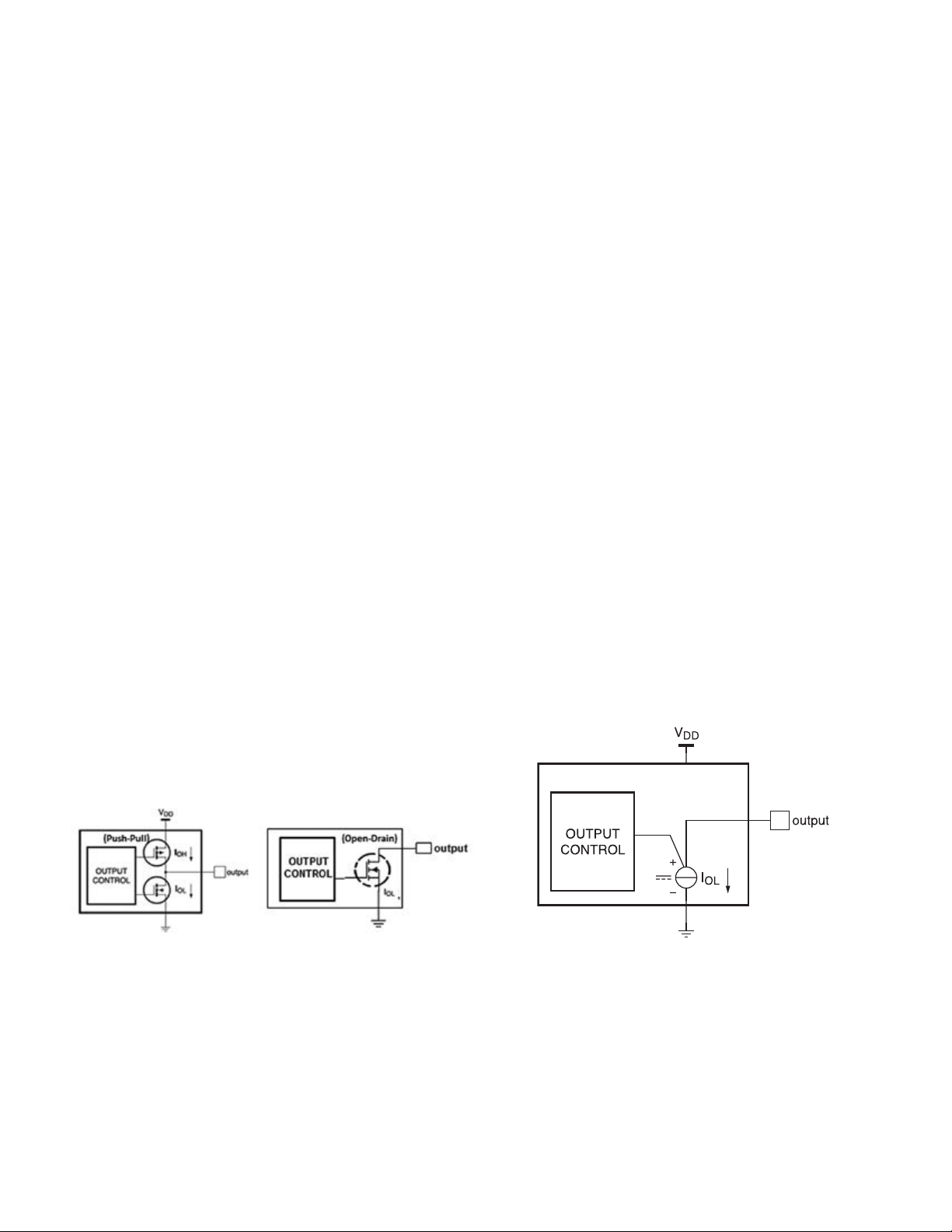
VOLTAGE-SWITCH DRIVERS
Voltage-switch output driver devices control the LED
connected to the output pin by switching the connection
to ground or supply on or off. A series resistor connected
between the LED and the device limits the current that
flows through the LED into the device.
Voltage-switch devices have the advantage of dissipating
the heat outside the device, in the series resistor. Therefore,
the device is insensitive to heat dissipation and is good for
driving multiple LEDs in series, with different forward-bias
voltages (Vf), from the same supply.
(a) Example Voltage-Switch Output Structure (b) Example Constant-Current Output Structure
CONSTANT-CURRENT DRIVERS
A current-regulated LED driver controls the current internally
which results in the LED light remaining constant even with
supply-voltage fluctuations. NXP constant-current LED drivers
are used for low-current luminary lighting applications
requiring accurate lighting control independent of supply
voltage, temperature, and LED forward-bias voltage.
The LED controllers are supported by application boards and daughter cards, an established manufacturing infrastructure
that supports high volumes and technical documents. NXP helps system designers make lighting affordable, in everything
from indoor consumer electronics and appliances to outdoor decorative lighting.
2 www.nxp.com
Page 3

LED CONTROLLERS SELECTION GUIDE
[1]
Device
PCA9550 Blinker 2
PCA9553 Blinker 4
PCA9551 Blinker 8
PCA9552 Blinker 16
PCA9530
PCA9533
PCA9531
PCA9532
PCA9632
PCA9633
PCA9634
PCA9635
PCA9685
PCA9624
PCA9622
PCA9626
PCA9952
PCA9955
PCA9955B
PCA9956B
PCA9957
PCA9959
PCA9745B
PCU9656
[1]
Typical value measured with VDD = 5.5 V, no load, VI = VDD or VSS and FSCL = 0 Hz
[2]
External clock input option
[3]
Build in gradation control
[4]
In-production AEC-Q100 compliant version only
[2]
[4]
[4]
[3]
Function
Dimmer
& blinker
Dimmer
& blinker
Dimmer
& blinker
Dimmer
& blinker
Dimmer
& blinker
Dimmer
& blinker
Dimmer
& blinker
Dimmer
& blinker
Dimmer 16
Dimmer
& blinker
Dimmer
& blinker
Dimmer
& blinker
Dimmer
& blinker
Dimmer
& blinker
Dimmer
& blinker
Dimmer
& blinker
Dimmer
& blinker
64-grid
Dimmer
& blinker
Dimmer
& blinker
Dimmer
& blinker
Number of LED Outputs
Operating Voltage Range
Standby Current
2.3 V–
1.9 µAVoltage
5.5 V
2.3 V–
5.5 V
2.3 V–
5.5 V
2.3 V–
5.5 V
2.3 V–
2
5.5 V
2.3 V–
4
5.5 V
2.3 V–
8
5.5 V
2.3 V–
16
5.5 V
2.3 V–
4
5.5 V
2.3 V–
4
5.5 V
2.3 V–
8
5.5 V
2.3 V–
16
5.5 V
2.3 V–
5.5 V
2.3 V–
8
5.5 V
2.3 V–
16
5.5 V
2.3 V–
24
5.5 V
3.0 V–
16
5.5 V
3.0 V–
16
5.5 V
3.0 V–
16
5.5 V-
3.0 V–
24
5.5 V
2.7 V–
24
5.5 V
2.7 V–
24
5.5 V
3.0 V–
16
5.5 V
2.3 V–
24
5.5 V
switch
1.9 µAVoltage
switch
1.9 µAVoltage
switch
2.1 µAVoltage
switch
1.9 µAVoltage
switch
1.9 µAVoltage
switch
1.9 µAVoltage
switch
2.1 µAVoltage
switch
0.005 µAVoltage
switch
3.8 µAVoltage
switch
3.8 µAVoltage
switch
3.8 µAVoltage
switch
2.2 µAVoltage
switch
2.1 µAVoltage
switch
3.2 µAVoltage
switch
6.0 µAVoltage
switch
100 µAConstant
current
100 µAConstant
current
170 µAConstant
current
Constant
100
µA
current
170
Constant
uA"
current
170 uAConstant
current
Constant
170
µA
current
Voltage
6 µA
switch
Type of LED Drive
25 mA 5 V
25 mA 5 V
25 mA 5 V
25 mA 5 V
25 mA 5 V
25 mA 5 V
25 mA 5 V
25 mA 5 V
-10 mA
25 mA
-10 mA
25 mA
-10 mA
25 mA
-10 mA
25 mA
-10 mA
25 mA
100 mA 40 V
100 mA 40 V
100 mA 40 V
57 mA 40 V
57 mA 40 V
57 mA 20 V
57 mA 20 V
32 mA 5.5 V
63 mA 5.5 V
57 mA 20 V
100 mA 40 V
Max LED Drive Current
5 V
5 V
5 V
5 V
5 V
Max LED Drive Voltage
Open drain
(Sink)
Open drain
(Sink)
Open drain
(Sink)
Open drain
(Sink)
Open drain
(Sink)
Open drain
(Sink)
Open drain
(Sink)
Open drain
(Sink)
Push/pull
(Configurable)
Push/pull
(Configurable)
Push/pull
(Configurable)
Push/pull
(Configurable)
Push/pull
(Configurable)
Open drain
(Sink)
Open drain
(Sink)
Open drain
(Sink)
Open drain
(Sink)
Open drain
(Sink)
Open drain
(Sink)
Open drain
(Sink)
Open drain
(Sink)
Open drain
(Sink)
Open drain
(Sink)
Open drain
(Sink)
Output Type
LED Pin Can Be Used as Input
Number of PWMs
Individual PWM Resolution
(Steps)
Group PWM Resolution (Steps)
Y 2 256 N/A Y N N N N N
Y 2 256 N/A N N N N N N
Y 2 256 N/A N N N N N N
Y 2 256 N/A N N N N N N
Y 2 256 N/A Y N N N N N
Y 2 256 N/A N N N N N N
Y 2 256 N/A N N N N N N
Y 2 256 N/A N N N N N N
4
N
256 64 Y Y N N N N
+ 1
4
N
256 256 Y Y Y N N N
+ 1
8
N
256 256 Y Y Y N N N
+ 1
16
N
256 256 Y Y Y N N N
+ 1
N 16 4096 N/A Y N Y Y N N
8
N
256 256 Y Y Y N N N
+ 1
16
N
256 256 Y Y Y N N N
+ 1
24
N
256 256 Y Y Y N N N
+ 1
16
N
256 256 Y Y Y Y Y Y
+ 1
16
N
256 256 Y Y N Y Y Y
+ 1
16
N
256 256 Y Y Y Y Y Y
+ 1
24
N
256 256 Y Y Y Y Y Y
+ 1
24
N
256 256 Y Y Y Y Y Y
+1
N N N N Y Y Y Y Y Y
16
N
256 256 Y Y Y Y N Y
+ 1
24
N
256 256 Y Y Y N N N
+ 1
Individual Brightness Control
Group Brightness Control
Output Enable/PWM Control
Programmable Output Delay
LED Error Detection
Thermal Shutdown
Interface
Number of Device Addresses
Hardware Reset
Individual PWM Frequency
Group PWM Frequency
Status
I2C,
2 Y
Fm
I2C,
1 N
Fm
I2C,
8 Y
Fm
I2C,
8 Y
Fm
I2C,
2 Y
Fm
I2C,
1 N
Fm
I2C,
8 Y
Fm
I2C,
8 Y
Fm
I2C,
1, 4 N 1.56 kHz
Fm+
I2C,
1, 4, 126 N 97 kHz
Fm+
I2C,
126 N 97 kHz
Fm+
I2C,
126 N 97 kHz
Fm+
I2C,
62 N
Fm+
I2C,
126 N 97 kHz
Fm+
I2C,
126 N 97 kHz
Fm+
I2C,
126 N 97 kHz
Fm+
I2C,
8 Y 31.5 kHz 122 Hz
Fm+
I2C,
16 Y 31.5 kHz 122 Hz
Fm+
I2C,
125 Y 31.5 kHz 122 Hz
Fm+
I2C,
125 Y 31.5 kHz 122 Hz
Fm+
SPI 10
Daisy-
MHz
Chain
SPI 10
Daisy-
MHz
Chain
SPI 25
25 Y 31.5 kHz 122 Hz
MHz
I2C,
64 Y 97 kHz 190 Hz
UFm
0.172 Hz
- 44 Hz
0.172 Hz
- 44 Hz
0.172 Hz
- 44 Hz
0.172 Hz
- 44 Hz
0.591 Hz
- 152 Hz
0.591 Hz
- 152 Hz
0.591 Hz
- 152 Hz
0.591 Hz
- 152 Hz
24 Hz -
1526 Hz
31.25
Y
kHz
Y N N
N/A
N/A
N/A
N/A
N/A
N/A
N/A
N/A
190 Hz
(6.25
kHz)
190 Hz
(97 kHz)
190 Hz
(97 kHz)
190 Hz
(97 kHz)
N/A
190 Hz
(97 kHz)
190 Hz
(97 kHz)
190 Hz
(97 kHz)
122 Hz
In
production
In
production
In
production
In
production
In
production
In
production
In
production
In
production
In
production
In
production
In
production
In
production
In
production
In
production
In
production
In
Production
In
production
In
production
In
production
In
production
In
production
In
production
In
production
In
production
www.nxp.com 3
Page 4

PCA9622 VOLTAGE-SWITCH LED DRIVER
APPLICATION EXAMPLE
RGBA Color
Mixing
LCD
Backlight
High-brightness
400 mA application
Keyboard
Backlight
PCA9955B CONSTANT CURRENT LED DRIVER
APPLICATION EXAMPLE
VDD = 3.3 V or 5.0 V
12C-BUS/SMBus
MASTER
RESET
1.6 kΩ 1.6 kΩ 10 kΩ
SDA
SCL
Œ
ISET
(1)
1.1 kΩ
(optional)
SCL
SDA
Œ
RESET
PCA9955B
REXT
AD0
AD1
AD2
V
SS
VDD
LED0
LED1
LED2
LED3
LED4
LED5
LED6
LED7
LED8
LED9
LED10
LED11
LED12
LED13
LED14
LED15
V
SS
Up to 20 V
• • •
• • •
• • •
• • •
• • •
• • •
• • •
• • •
• • •
• • •
• • •
• • •
• • •
• • •
• • •
• • •
C
+
10 μF
ARCHITECTURAL LIGHTING
MOBILE PHONE APPLICATION EXAMPLE
AUTOMOTIVE INSTRUMENT CLUSTER
CAR RADIO BACKLIGHT
4 www.nxp.com
Page 5

APPLICATION SUPPORT
For added application support, NXP offers the following application reports on the LED driver family devices:
Description Title
Driving LED Light Bars
Using NXP Solutions
I2C Devices for LED
Display Control
PCA9632 1.8 V I2C-bus
and 2.8 V VDD Operation
A Guide to Designing for
ESD and EMC
PCA9955 Demonstration
Board OM13330
PCA9956B
Demonstration Board
OM13321
PCA9955B
Demonstration Board
OM13483
PCA9532 Demonstration
Board OM13528
PCA9632 Demonstration
Board OM13269
PCA9745B
Demonstration Board
OM13524
Gaming Suitcase Demo
System
PCA9957
Demonstration Board
OMPCA9957LEDEV
PCA9959
Demonstration Board
OMPCA9959LEDEV
AN10579_1 All LEDs App note https://www.nxp.com/docs/en/application-note/AN10579.pdf Feb-1-07
AN264_1
AN11169 PCA9632 App note https://www.nxp.com/docs/en/application-note/AN11169.pdf Mar-26-12
AN10897 All LEDs App note https://www.nxp.com/docs/en/application-note/AN10897.pdf Jan-19-10
UM10572 PCA9955 User guide https://www.nxp.com/docs/en/user-guide/UM10572.pdf Jun-7-12
UM10709 PCA9956B User guide https://www.nxp.com/docs/en/user-guide/UM10709.pdf Aug-11-17
UM10729-1 PCA9955 User guide https://www.nxp.com/docs/en/user-guide/UM10729.pdf Aug-1-17
UM10988
UM10528 PCA9632 User guide https://www.nxp.com/docs/en/user-guide/UM10528.pdf Jan-30-12
UM11009 PCA9745B User guide https://www.nxp.com/docs/en/user-guide/UM11009.pdf Jun-27-16
UM10563
UM11196 PCA9957 User guide https://www.nxp.com/docs/en/user-guide/UM11196.pdf Apr-27-20
UM11436 PCA9959 User guide https://www.nxp.com/docs/en/user-guide/UM11436.pdf Apr-27-20
Applicable
Devices
PCA9530/1/2/3
PCA9550/1/2/3
PCA9530/31/32/33
PCA9550/51/52/53
LED and stepper
motor
Type URL
App note https://www.nxp.com/docs/en/application-note/AN264.pdf Jul-22-02
User guide https://www.nxp.com/docs/en/user-guide/UM10988.pdf May-2-16
User guide https://www.nxp.com/docs/en/user-guide/UM10563.pdf Aug-9-12
Document
Date
For more information, visit http://www.nxp.com.
NXP offers evaluation modules and demo boards that can be used to develop software and evaluate the performance of the
LED controllers.
OM13483—PCA9955B 16-CHANNEL LED
DEMO BOARD
The OM13483 board is an add-on to the 9-pin connector
of NXP’s Fm+ I2C Bus development board. This daughter
board makes it easy to test and design with the PCA9955B,
a 16-channel Fast-mode Plus (Fm+) 57 mA constant current
LED controller for LED strings up to 20 V.
OM13321—PCA9956B 24-CHANNEL LED
DEMO BOARD
The OM13321 board is an add-on to the 9-pin connector
of NXP’s Fm+ I2C Bus development board. This daughter
board makes it easy to test and design with the PCA9956B,
a 24-channel Fast-mode Plus (Fm+) 57 mA constant current
LED controller for LED strings up to 20 V.
www.nxp.com 5
Page 6

OMPCA9957LEDEV—PCA9957 24-CHANNEL LED
DEMO BOARD
The OMPCA9957LEDEV board is an add-on to Arduino®
shield connector of NXP’s OM13089 MCU board. This
daughter board makes it easy to test and design with the
PCA9957, a 24-channel SPI interface and 32-mA constant
current LED controller. Outputs allow up to 5.5 V for
LED supply.
OMPCA9959LEDEV—PCA9959 24-CHANNEL LED
DEMO BOARD
The OMPCA9959LEDEV board is an add-on to Arduino
shield connector of NXP’s OM13089 MCU board. This
daughter board makes it easy to test and design with the
PCA9959, a 24-channel SPI interface and 63-mA constant
current LED controller. Outputs allow up to 5.5 V for
LED supply
For current information about NXP products and documentation,
please visit www.nxp.com/interface.
NXP and the NXP logo are trademarks of NXP B.V. All other product or service names are the property of their respective owners.
© 2021 NXP B.V.
Document Number: 939775017588 REV 2
 Loading...