

Page 1

GeForce FX 5900 XT Series
VGA Card
User's Guide
Page 2

100%
Disclaimer
The information in this document is subject to change without notice and does not represent a
commitment on the part of the vendor. No warranty or representation, either expressed or implied, is
made with respect to the quality, accuracy or fitness for any particular purpose of this document. The
manufacturer reserves the right to make changes to the content of this document and/or the products
associated with it at any time without obligation to notify any person or organization of such changes.
In no event will the manufacturer be liable for direct, indirect, special, incidental or consequential
damages arising out of the use or inability to use this product or documentation, even if advised of the
possibility of such damages. This document contains materials protected by copyright. All rights are
reserved. No part of this manual may be reproduced or transmitted in any form, by any means or for
any purpose without express written consent. Product names appearing in this document are
mentioned for identification purposes only. All trademarks, product names or brand name s appearing in
this document are registered property of their respective owners
.
Printed in Taiwan
FCC Compliance Statement
This equipment has been tested and found to comply with limits for a Class B digital device, pursuant
to Part 15 of the FCC rules. These limits are designed to provide reasonable protection against harmful
interference in residential installations. This equipment generates, uses, and can radiate radio frequency
energy, and if not installed and used in accordance with the instructions, may cause harmful
interference to radio communications. However, there is no guarantee that interference will not occur in
a particular installation. If this equipment does cause interference to radio or television equipment
reception, which can be determined by turning the equipment off and on, the user is encouraged to try
to correct the interference by one or more of the following measures:
- Reorient or relocate the receiving antenna.
- Move the equipment away from the receiver.
- Plug the equipment into an outlet on a circuit different from that to which the receiver is
connected.
- Consult the dealer or an experienced radio/television technician for additional suggestions.
Only equipment certified to comply with Class B should be attached to this equipment, and must have
shielded interface cables. You are cautioned that any change or modifications to the equipment not
expressly approved by the party responsible for compliance could void your authority to operate such
equipment. This device complies with Part 15 of the FCC rule. Operation is subjected to the fo llowing
two conditions:
1) This device may not cause harmful interference.
2) This device must accept any interference received, including interference that may cause
undesired operation.
Nov 2003
OST-CONSUMER
RECYCLED PAPER
CONTENTS
Chapter 1
Chapter 2 Hardware Setup
Chapter 3
Chapter 4
Appendix..................................................................................27
Introduction...............................................................1
Product Specifications.......................................................................................... 1
Package Contents.................................................................................................. 2
System Requirements ........................................................................................... 2
............................................................3
Installing the Hardware ....................................................................................... 3
硬體安裝................................................................................................................. 4
Installation du matériel ........................................................................................ 5
하드웨어 설치....................................................................................................... 6
Installation der Hardware.................................................................................... 7
Driver Setup ..............................................................8
Introduction...........................................................................................................8
DirectX 9.0............................................................................................................. 8
Display Drivers Setup......................................................................................... 10
Display properties...................................................12
nView Display Setup........................................................................................... 13
Performance and Quality Settings .................................................................... 18
Direct 3D Settings................................................................................................ 19
OpenGL Settings................................................................................................. 20
Overlay Controls................................................................................................. 21
TroubleShooting.................................................................................................. 22
NVRotate.............................................................................................................. 23
Temperature Setting (For specific products only)........................................... 24
Refresh Rate Override........................................................................................ 25
Change Resolutions............................................................................................. 25
Desktop Management......................................................................................... 26
Screen Menus....................................................................................................... 26
WinCinema.......................................................................................................... 27
3Deep E-color (Optional) ................................................................................... 41
WinProducer3 (Optional) .................................................................................. 45
Page 3

1
Product Specifications
2
Interface
AGP 4x/8x and AGP texturing support
Chipset
NVIDIA GeForce FX5900 XT Series
Memory Interface
Supports 128 MB DDR SDRAM
Features
256-bit advanced memory interface
256-bit graphics architecture
400 MHz internal RAMDAC
22.4 GB/sec memory bandwidth
8 pixels per clock rendering engine
16 texels per pixel with 8 textures applied per clock
NVIDIA CineFX 2.0 Engine
Advanced Display Pipeline with full nView Capabilities
High-performance, high-precision 3D rendering engine
High-Performance 2D rendering engine
UltraShadow technology
Intellisample HCT Performance Technology
Digital Vibrance Control (DVC) 3.0
NVIDIA nView multi-display technology
Unified Driver Architecture (UDA)
High quality video playback
Dual, 400MHz RAMDACs for display resolutions up to and including
2048x1536 @ 85Hz
Integrated NTSC/PAL TV encoder support resolutions up to 1024x768
without the need for panning with built-in Macrovision copy protection
DVD and HDTV-ready MPEG-2 decoding up to 1920x1080i
resolutions
Support for dual-link DVI for compatibility with next-generation flat
panel displays with resolutions greater than 1600x1200 without the
need for reduced blanking
Full Software Support
Microsoft DirectX optimizations and support
Full OpenGL 1.4 and lower support
Complete support DirectX 9.0 and lower
WHQL-certified Windows 2000 / XP (for Windows 9x / ME versions
please visit NVIDIA’s website for the latest update on drivers)
Chapter 1
User’s Guide
Introduction
Chapter 1
Chapter 1
Others
TV-out
DVI-I (Optional)
VIVO (Optional)
Package Contents
1. GeForce FX5900 XT Series VGA card
2. User's Guide
3. Driver Pack
- Windows 2000/XP drivers (for Windows 9x / ME versions please visit
NVIDIA’s website or see later update on drivers)
- 3Deep (Optional)
- WinDVD 6 Channel
- WinDVD Creator
- WinRip
4. WinProducer 3.0 (Optional)
5. MDK2
6. Game Pack (5 in 1)
- Age of Wonders2
- Serious Sam2
- Rally Trophy
- Max Panye
- Tropico
7. S-Video to S-Video cable
8. S-Video to AV cable (Optional)
9. DVI – I to VGA Adapter
10. Composite Cable (Optional)
11. VIVO cable (Optional)
System Requirements
Computer System
Intel Pentium® II or newer compatible CPU (Intel Pentium® III or
AMD Athlon® or newer CPU’s recommended)
VGA/Super VGA monitor, supporting minimum 640x480 resolution.
64MB RAM or higher.
15MB HDD space.
CD-ROM or DVD-ROM Driver.
DirectX 9.0 and lower.
Windows 2000 / XP operation system (for Windows 9x / ME versions
please visit NVIDIA’s website or see later update on drivers)
User’s Guide
Page 4
Chapter 2
3
4
Chapter 2 Hardware Setup
Installing the Hardware
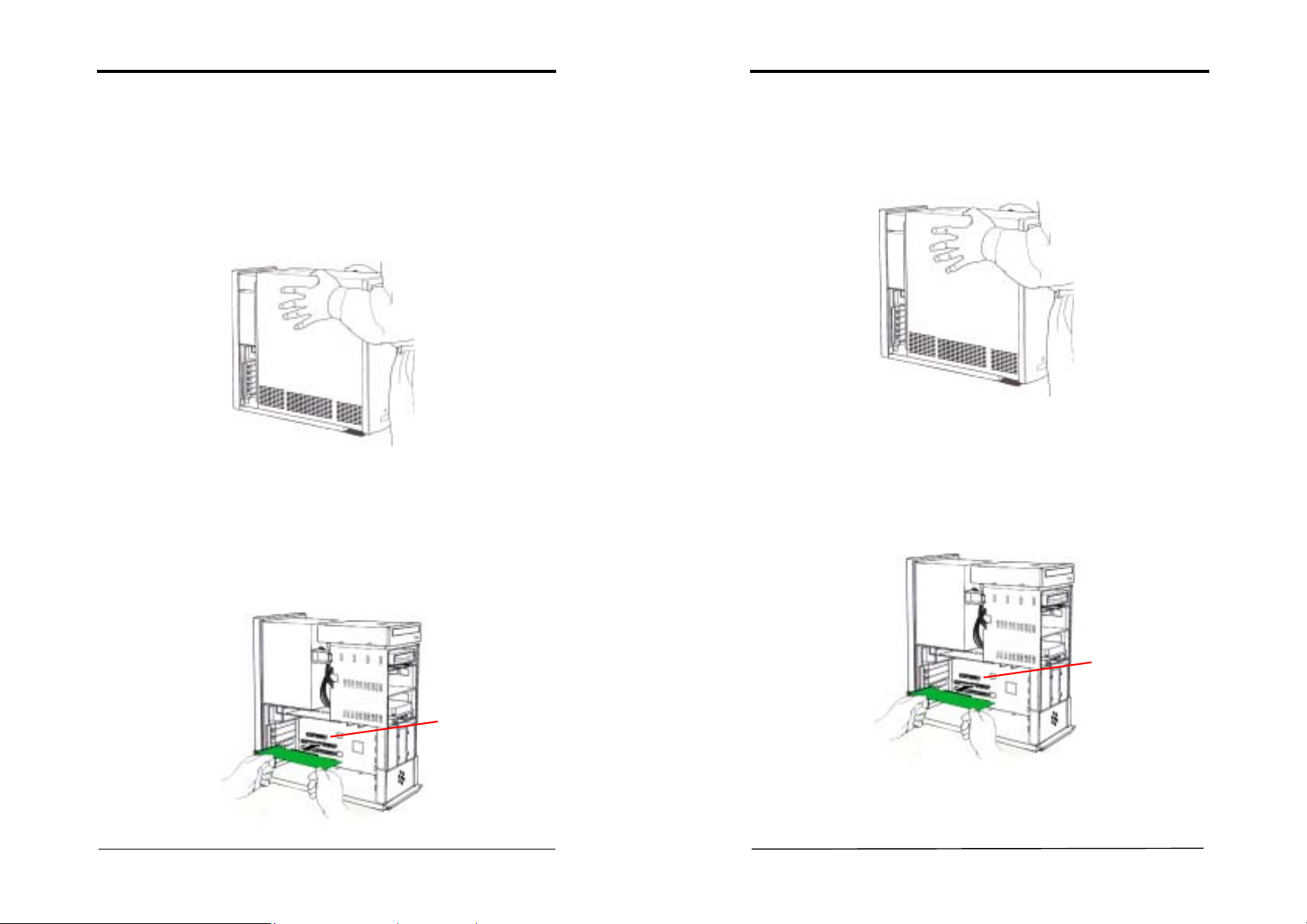
1. Turn off the computer's power and make sure the system is properly
grounded (leave the power cord connected). Then disconnect the monitor
signal cable.
2. Remove the computer chassis cover. Be sure to discharge your body's static
electricity by touching the metal area of the computer each time before
touching both the old and new VGA cards.
3. Remove the old card, if it exists.
4. Grasp the edge or bracket of the card, align your card with an empty AGP
expansion slot and slide it into place.
5. Replace the screw to fasten the card onto the chassis, and replace the
computer chassis cover.
6.
Plug the monitor cable into your card, and then turn on the computer and the
monitor.
Chapter 2
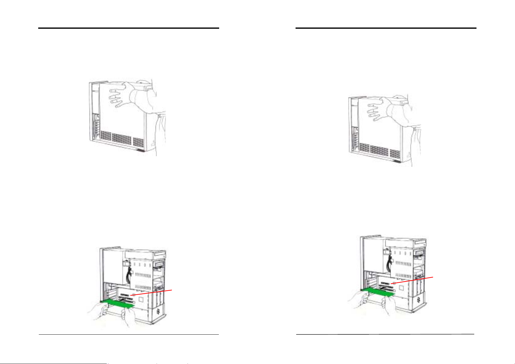
硬體安裝
1. 關掉電腦的電源,並且確定拔掉電源線,然後拔除螢幕的訊號線。
移開電腦的外殼蓋。在每次安裝新的和舊的顯示卡前,請觸摸電腦的金
2.
屬部位,以確保排出身體中之多餘靜電。
假如你有舊的顯示卡請先移除。
3.
4. 握緊你的顯示卡,小心地將顯示卡插入空的 AGP 插槽中。
用螺絲將顯示卡固定於機殼中,並且將電腦的外殼蓋放回原處,並用螺
5.
絲栓緊。
連接螢幕的排線於顯示卡上,並且打開電腦和螢幕的電源開關。
6.
AGP slot
AGP slot
User’s Guide
User’s Guide
Page 5
Chapter 2
5
6
AGP slot
Chapter 2
Installation du matériel
Eteignez
1.
votre ordinateur et
2. Enlevez le couvercle ou les panneaux de côté de votre ordinateur (consultez
le manuel d’instructions de votre ordinateur pour les instructions de montage
et de démontage).
3. Enlevez la carte graphique AGP présente -o u – enlevez la languette de métal
qui recouvre l’emplacement du connecteur AGP.
4. Alignez le côté de votre carte où se trouvent les connecteurs avec
l’emplacement du connecteur AGP et appuyez fermement jusqu’à ce qu’elle
soit complètement mise ne place (ne SURTOUT PAS forcer la carte dans
son emplacement – appliquez une poussée uniforme de chaque côté de la
carte).
5. Visez la carte au châssis, et remonté le couvercle du boîtier.
6. Branchez le cordon VGA à la carte graphique et reconnectez votre moniteur
ainsi que le reste des câbles.
déconnecté
votre écran.
하드웨어 설치
1. 먼저 컴퓨터의 전원을 차단하고 전원이 완전히 차단되었는지 확인한 후에
2. 컴퓨터 케이스의 덮개를 열고 VGA 카드를 장착하기에 앞서 컴퓨터를
3. 만약
4. 케이스 뒷면 브라켓 장착 부분과 PCI 확장 슬롯에 수직이 되도록 하여
5. VGA 카드를 장착한 후 컴퓨터 케이스 덮개를 씌워 주십시오.
6. VGA
모니터 시그널 케이블을 분리해 주십시오.
전자기로부터 보호하기 위해 전자기로부터 안전한 복장 및 도구를 착용하거나
이용해 주십시오.
구형카드가 시스템에 장착되어 있다면 먼저 구형카드를 시스템에서
분리해 주십시오
카드를 조심스럽게 PCI 확장 슬롯에 장착해 주십시오.
카드에 모니터 케이블을 연결한 후 컴퓨터 본체와 모니터의 전원을
켜주십시오.
.
AGP slot
User’s Guide
User’s Guide
Page 6
Chapter 2
7
8
Installation der Hardware
Schalten Sie
1.
den Computer
richtig geerdet ist (lassen Sie das Netzkabel sowohl am PC als auch an
der Netzsteckdose angeschlossen).
Monitors vom VGA-Anschluß.
2. Entfernen Sie die Abdeckung des PC-Gehäuses. Stellen Sie sicher, dass Sie
sich jedes mal durch Berührung des Metallgehäuses von statischer
Elektrizität befreien, bevor Sie die alte oder neue VGA-Karte anfassen!
3. Remove the old card, if it exists.
4. Grasp the edge or bracket of the card, align your card with an empty AGP
expansion slot and slide it into place.
5. Replace the screw to fasten the card onto the chassis, and replace the
computer chassis cover.
6.
Plug the monitor cable into your card, and then turn on the computer and the
monitor.
aus,
und stellen Sie sicher, dass das Gerät
Trennen Sie jetzt das Signalkabel des
Chapter 3
Chapter 3
Driver Setup
Introduction
This chapter explains how to install AGP VGA card drivers using the VGA Driver
Setup tool that is included in the CD-ROM that came with your AGP VGA card.
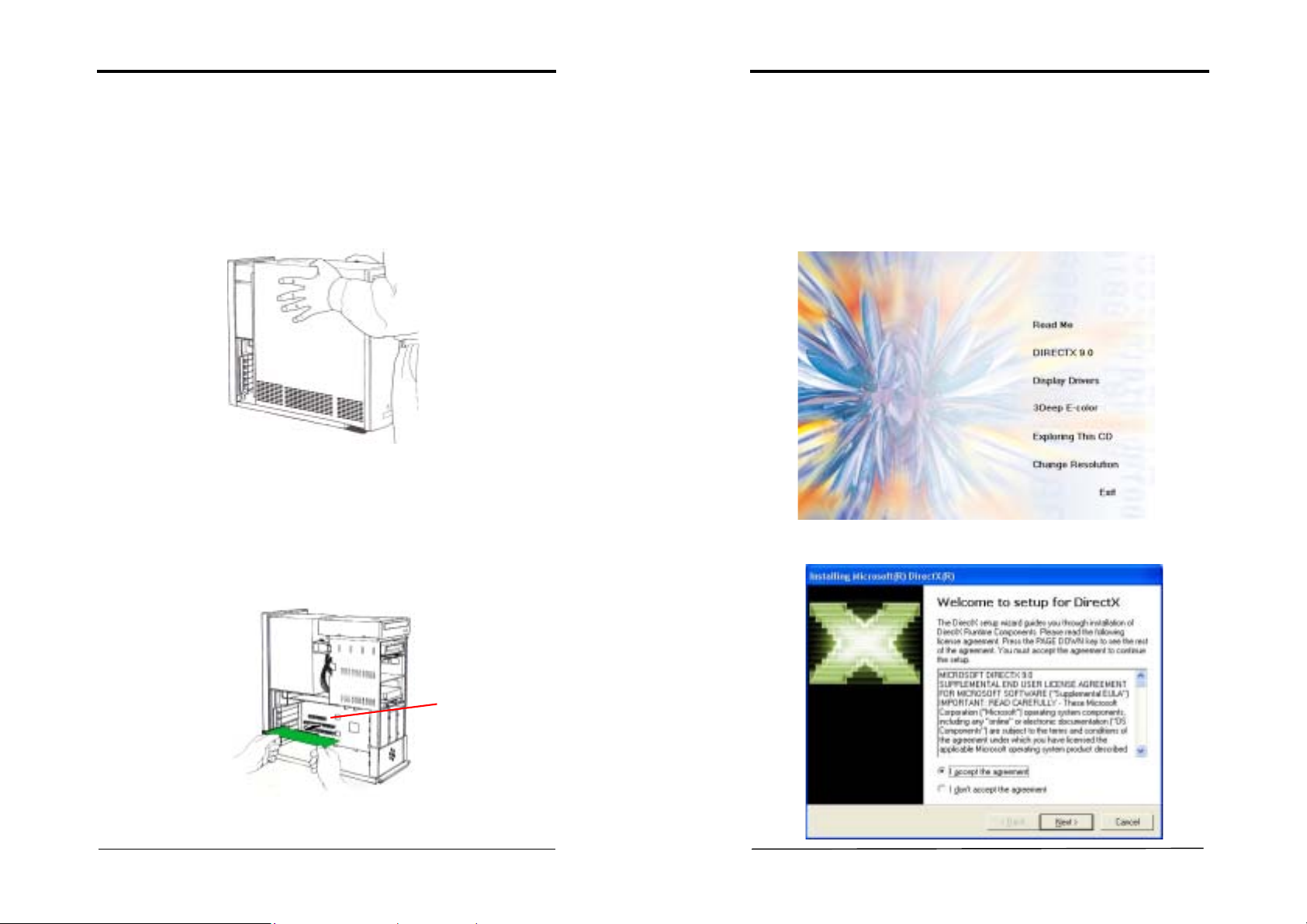
DirectX 9.0
1. If an older version of DirectX has been installed in the system, please click
DIRECTX 9.0
on [
2. After reading the license agreement, please click [
] to upgrade to the latest version.
Next >
] to continue.
AGP slot
User’s Guide
User’s Guide
Page 7
Chapter 3
9
10
Chapter 3
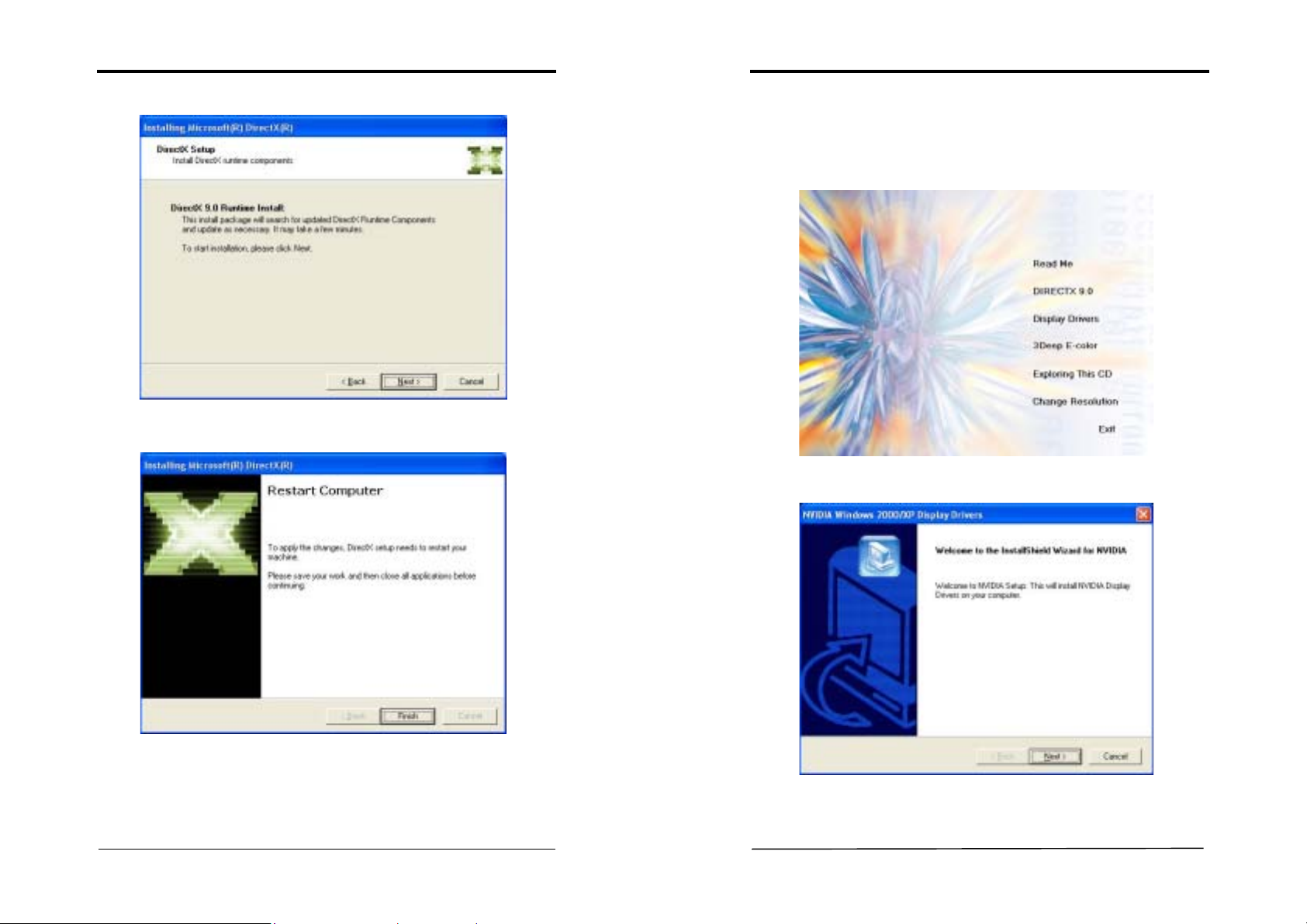
3. Please click [Next >] to continue.
4. Please click
[Finish
] to complete the setup process.
Display Drivers Setup
F
or Driver setup in Win98se/ME/2000/XP mode, please follow the steps below.
1. Insert VGA Driver Package CD into CD-ROM driver.
2. Click on [
3. Please click [
Display Drivers
Next >
] to continue.
] to begin driver installations.
User’s Guide
User’s Guide
Page 8
Chapter 3
11
12
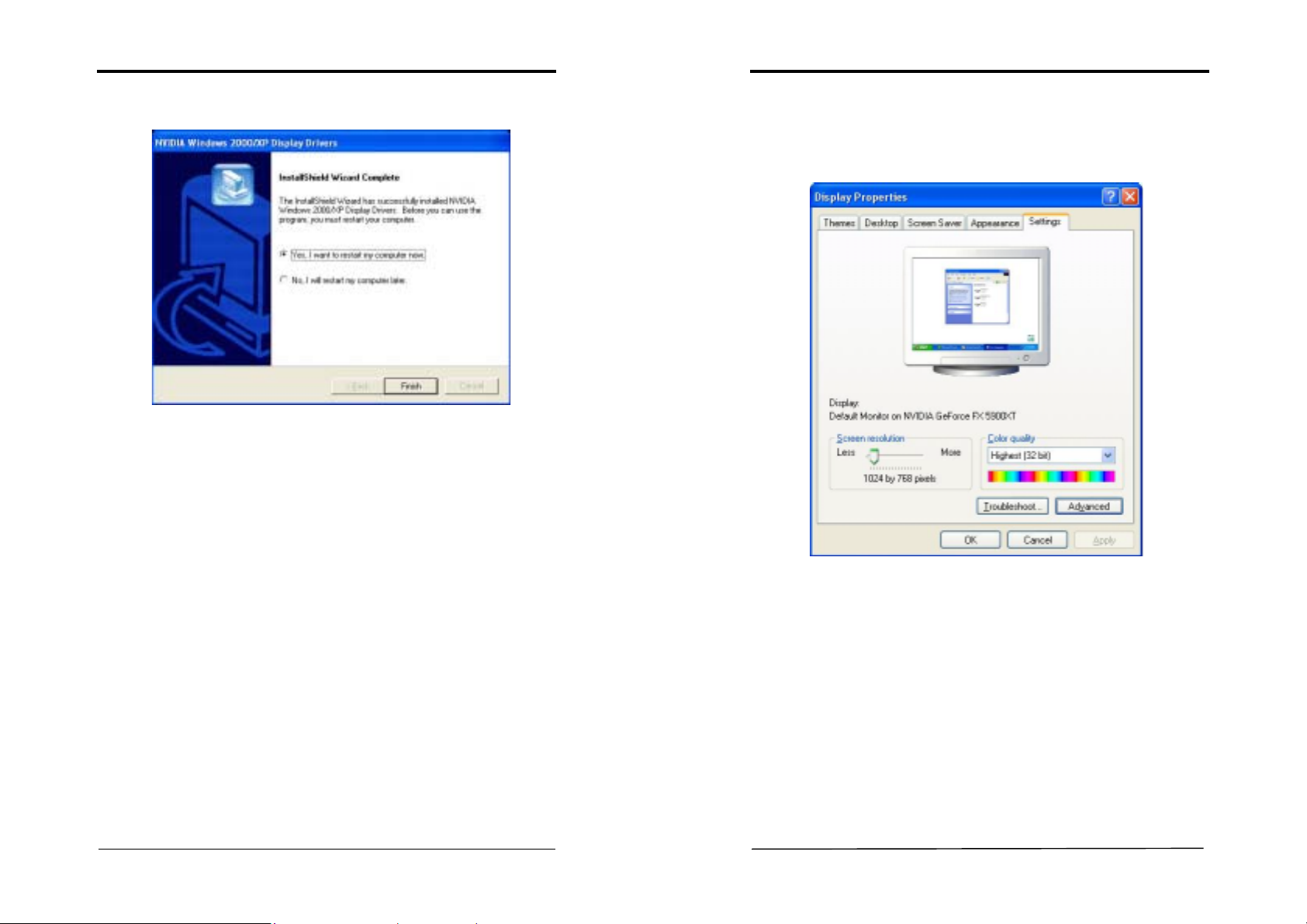
4. Please select [Yes] to restart computer now or [No] for restart later, then
Finish
click [
] to complete the installation.
Chapter 4
Chapter 4
In order to open
Control Panel
[
blank Windows® desktop area and choose [
Display Properties
Display Properties
Display Properties
] ->[
window below will show on your screen:
Display properties
window, select from [
Start
]. Otherwise, you may simply right-click the
Properties]
in the pop-up menu. The
] -> [
Settings
] ->
Please click the [Advanced] button to enter the advanced setup for your display
card.
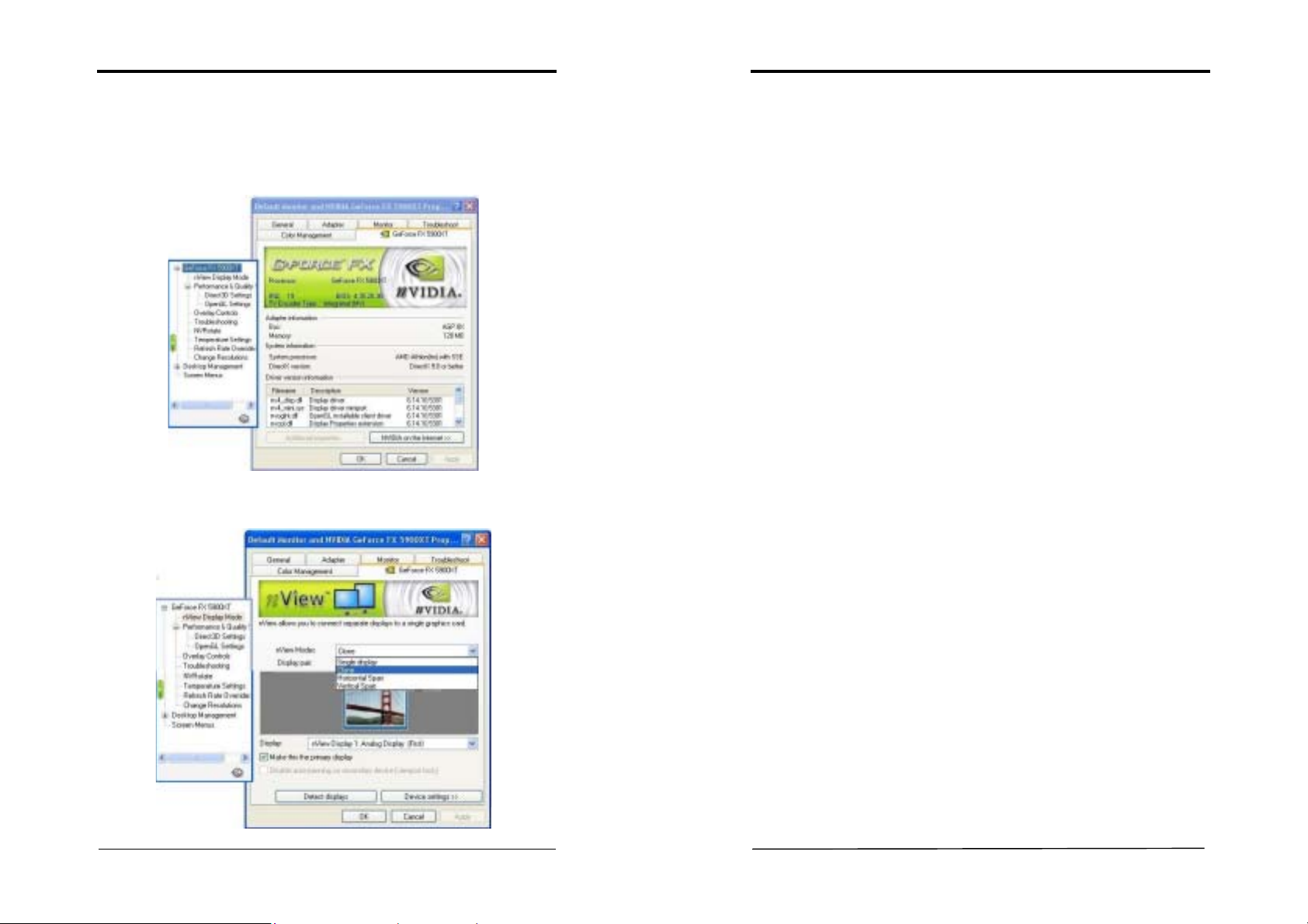
Choose [GeForce FX5900XT] series tab in the pop-up menu to access further
settings on VGA card feature.
User’s Guide
User’s Guide
Page 9
Chapter 4
13
14
nView Display Setup
In order to open Display Properties window, select from [Start] ->[Settings] ->
[Control Panel] -> [Display Properties] to open the submenu. From [Display
Properties
select the various functions of this VGA card.
Please click on nView Display Mode to enter its submenu that allows you to setup
the various nView options.
] -> [
Settings
] -> [
Advanced
GeForce FX5900XT
] -> [
] tab we can
Chapter 4
nView Modes
1)
a)
Single display
Selects the standard, single display mode. Use this mode if you have only one
display device attached to your NVIDIA graphics adapter.
b)
Clone
This mode outputs an exact copy of the primary display on the secondary device.
c)
Horizontal Span
This mode allows you to extend the Windows desktop across two display devices
horizontally. In this mode the two displays combine to form a wide, spanned display
surface, which is useful when viewing items that are wider than a single display.
d)
Vertical Span
This mode allows you to extend the Windows desktop across two display devices
vertically. In this mode the two displays combine to form a tall, spanned display
surface, which is useful when viewing items that are larger than a single display.
Current Display
2)
If more than one device is connected and you have switched to a mode other than the
Standard one, you can select the current display of your choice.
You can also click on the monitor image directly above the display control to select
it as the current display.
Notes:
nView Display Devices select:
First Display
Second Display
Third Display
D-Sub Connector
DVI-I Connector
TV-out
Make this the primary display
3)
Use this option to select which display contains the top left corner of the desktop.
The most obvious effect of this option is that it swaps the positions of the monitor
images.
Disable auto-panning on secondary device (viewport lock)
4)
Turning on this feature locks the current pan position on the secondary clone display.
This lets you effectively freeze the virtual desktop at a certain position, which is
useful for presentations or fine-detailed work in applications.
User’s Guide
User’s Guide
Page 10

Chapter 4
15
16
Detect Displays
5)
Click to detect all displays connected to this video adapter. Use this feature if you
have plugged in any displays after the control panel was opened.
Device Setting >>
6)
Click this button to set up or change settings related to the output device used for the
current display.
Chapter 4
a) Color Correction:
The slider control allows you to adjust the brightness, contrast or gamma
values for the selected color channel.
The color correction controls help you to compensate for variations in
luminance between a source image and its output on a display device. When
you are working with image processing applications, this helps provide more
accurate color reproduction of images (such as photographs) that are displayed
on your monitor.
Also, many 3D-accelerated games may appear too dark to play. Increasing
the brightness and/or the gamma value equally across all channels makes these
games appear brighter and more playable.
User’s Guide
User’s Guide
Page 11

Chapter 4
17
18
Chapter 4
b) Device Adjustments
i) Screen Adjustment
This will access the Screen Adjustment panel as below.
This allows you to adjust the center of your screen, to adjust the screen
position, move the mouse over the monitor image and drag the desktop to the
desired position while holding down the primary mouse button. Use the arrow
positioning buttons for fine adjustments. You can also click the [
Default
button to return to its original state. Click [OK] when you finish adjusting the
screen.
ii) Display Timing
This option allows users to select the various timing mode for the monitor. Click
[Restore Defaults] to restore the default timing mode of the monitor.
User’s Guide
Performance and Quality Settings
]
1)
Performance
Drag the slider to select the performance setting (as described below) for quality
enhancements in Direct3D and OpenGL applications.
Antialiasing
2)
Antialiasing is a technique used to minimize the "stairstep" effect sometimes
seen along the edges of 3D objects. This option automatically enables the
optimal antialiasing settings for those 3D applications that support antialiasing.
Anisotropic Filtering
3)
Availability of options described below may depend on the NVIDIA GPU you
are using.Use this slider by dragging it to set the degree of anisotropic filtering
for improved image quality. Enabling this option improves image quality at the
cost of performance.
Texture Sharpening
4)
To improve image quality, select this option to sharpen textures when running
3D applications with antialiasing enabled.
User’s Guide
Page 12

Chapter 4
19
20
Chapter 4
Direct 3D Settings
This tab allows you to adjust the values of
Mipmapping and PCI Texture Memory Size for 3D games.
1)
Performance and Compatibility Options
This option contains items that allow you to set up the options influencing the
performance and compatibility in 3D games.
Mipmap Detail Level
2)
This option allows you to set up the mipmap level for a higher performance or
better image effects.
PCI Texture Memory Size
3)
This option allows you to adjust the size of the PCI texture memory. For some
applications using the Direct3D technology, typing a higher value in this spin
box may significantly increase the performance. However, this option does not
work on display adapter using an AGP bus.
Custom Direct3D Settings:
4)
This option allows you to save your settings for future reference.
Performance and Compatibility,
OpenGL Settings
This tab allows you to adjust the
OpenGL application.
erformance and Compatibility Options
1) P
This feature allows you to set up the various options influencing the performance
and compatibility in your OpenGL applications.
Default Color Depth for Textures
2)
This option determines the default textures of a specific color depth in OpenGL
applications.
Buffer Flipping Mode
3)
When running the OpenGL application under Full-Screen mode, turning on the
page- flipping function may significantly increase the performance.
Vertical Sync
4)
This option allows you to choose the type of vertical sync.
Performance and Compatibility Options
for your
User’s Guide
User’s Guide
Page 13

Chapter 4
21
22
Chapter 4
Overlay Controls
Use these controls to adjust the quality of video or DVD playback on your monitor.
You can independently control the
Brightnes
achieve optimal image quality during video or DVD movie playback on your
computer.
Zoom control:
Let you zoom in on or out of the selected portion of the video
playback screen.
Contrast, Hue
s,
and
Saturation
to
TroubleShooting
1)
Display the Media Center icon in the taskbar:
Adds the NVIDIA Media icon to the Windows taskbar by checking the
appropriate box on the screen. The icon allows you to apply any of the custom
Direct3D, OpenGL or color settings on the fly from a convenient pop-up menu.
The menu also contains items for restoring default settings and accessing the
Display Properties dialog box.
Detect Display
2)
Click this button to allow detection of any new displays added for the nView
Display Mode.
Restore Defaults
3)
Restore defaults
Click [
] to restore the default timing mode of the monitor.
User’s Guide
User’s Guide
Page 14

23
NVRotate
This is the default setting that will leave the screen in its
24
een 180 degrees upside
This will rotate the display screen 270 degrees (i.e. 90
The NVRotate feature lets you view your Windows desktop in Landscape or
Portrait
mode. You can rotate desktop by 90, 180 or 270 degrees.
Chapter 4
Chapter 4
Inverted Landscape (180 degree rotation)
3)
This will rotate the display scr
down.
Portrait (90 degree rotation)
4)
degrees to the left).
Temperature Setting (For specific products only)
This gives an indication of the current status of the GPU temperature setting.
Landscape (0 degree rotation)
1)
original state.
Portrait (90 degree rotation)
2)
This will rotate the display screen 90 degrees to the right.
User’s Guide
User’s Guide
Page 15

Chapter 4
25
26
Chapter 4
Refresh Rate Override
This tab allows you to select
applications.
Change Resolutions
Refresh Rate Override
to be used in Direct3D
Desktop Management
Enables the NVIDIA Desktop Manager:
The NVIDIA Desktop Manager enables additional functions such as hot keys for
window management, re-centering of dialog boxes, and zooming in when nView’s
multi-monitor configurations are in use. The Desktop Manager also adds support for
multiple desktops to help you better organize your application workspace.
Screen Menus
This gives an indication of the current status of the GPU temperature setting.
This option gives the details of the screen resolution and allows users to change
screen resolution, color quality and refresh rates for the monitor. In Custom
Resolutions and Refresh Rates, users can customize their own resolutions and
refresh rates by clicking [
Add
] or [
Remove
] button. When checking the [
Only show
custom modes] box only custom modes are shown.
User’s Guide
User’s Guide
Page 16

27
Appendix
28
WinCinema
1. Enter personal information on boxes below to register the product.
2. Choose [
WinDVDCreator and WINRIP, and [Clear All] to deselect them. Click
Next >
[
Select All
] to proceed.
] to select all the products, in this case
Appendix
WINDVD
Appendix
WinDVD
1)
It is a simple-to-use software DVD player combining all the features of a standard
consumer DVD player with some very advanced functionality only possible on a
software DVD player.
,
User’s Guide
User’s Guide
Page 17

Appendix
29
30
Appendix
1. Please click [Next >] to begin the setup process.
2. After reading the license agreement, please click [Yes] to continue.
3. Please select a folder where the program will be installed and click [Next >]
to proceed.
4. Please select one folder name from existing folders list and click [Next >] to
proceed.
User’s Guide
User’s Guide
Page 18

Appendix
31
32
Appendix
5. Please select the default player by checking the specific boxes and click
Next>
[
] to proceed.
6. Click on [Finish] to complete the installation process.
WinDVD Creator Setup
2)
WinDVD Creator's storyboard interface makes the entire DVD-making process as
easy as moving pictures around on your screen.
There are four Easy Steps to make your DVD: Capture, Edit, Author & Make
Movie.
1. Please click [Next >] to begin the setup process.
User’s Guide
User’s Guide
Page 19

Appendix
33
34
Appendix
2. After reading the license agreement, please click [Yes] to continue.
3. Please select a folder where the program will be installed and click [
to proceed.
Next >
4. Please select one folder name from existing list of folders and click [Next >]
to proceed.
]
5. Please check the box to install the required third party product and click
[Next >] to proceed.
User’s Guide
User’s Guide
Page 20

Appendix
35
36
Appendix
6. Click on [Finish] to complete the installation process.
WinRip 2.1 Setup
3)
WinRip lets you record, store, organize, and enjoy you music collection - on your PC,
CD player, and portable player. WinRip's IDI technology adds synchronized lyrics to
your songs, then use the Karaoke and other DSP effects for a great party.
1. Please click [Next >] to begin the setup process.
2. After reading the license agreement, please click [
Yes
] to continue.
User’s Guide
User’s Guide
Page 21

Appendix
37
38
Appendix
3. Please select a folder where the program will be installed and click [Next >]
to proceed.
4. Please select one folder name from existing list of folders and click [Next >]
to proceed.
5. Click on [Start >] to begin WinRip Configuration Wizard.
6. Choose [
Select All
] to select all file extension types for WinRip and click
[Next >] to continue.
User’s Guide
User’s Guide
Page 22

Appendix
39
40
Appendix
7. Click on [Next >] to continue.
8. Select the type of recording format and click [Next >] to continue.
9. Click on [Finish] to complete the configuration process.
10. Click on [
Finish
] to complete the setup.
User’s Guide
User’s Guide
Page 23

Appendix
41
42
Appendix
3Deep E-color (Optional)
3Deep ensures that your monitor displays 3D games with accurate lighting and
shading exactly the way the creator intended. 3Deep delivers the precise imagery
that the developer spent months working to achieve.
1. Please click [
2. After reading the license agreement, please click [
Next >
] to continue.
Yes
] to continue.
3. Please click [Next >] to continue.
4. Please click [OK] to allow the 3Deep E-color to tune up your display.
5. Choose your screen to be either CRT or FLAT PANEL and then press
Next >
[
] to continue.
User’s Guide
User’s Guide
Page 24

43
Please follow the setup procedure below to tune up your Display.
44
6. Please click [
7. Please check the box for the required files and then click [
Next >
] to continue installing 3Deep E-color.
Next >
installation process.
Appendix
] to end the
Appendix
Tuning Up Instruction
Double-click on the E-Color icon in your system tray and then click on the 'Tune-Up'
tab.
1. Click on the 'Tune-up' button.
2. Complete the quick and easy E-Color Wizard, and then connect to the
Internet.
3. When connected, 3Deep will complete the process enabling you to see
E-Color Corrected images.
For Your Best Result
1. Let your monitor warm up for at least 30 minutes before beginning the
E-Color Wizard (TM). This process allows the colors to stabilize.
2. If you have a third-party monitor calibration system installed (e.g., EFIcolor,
AGFA FotoTune, or another), use either that system or 3Deep. Do not use
both calibration systems. Using both systems will mis-calibrate the monitor.
Search 3Deep Help for instructions for your application.
3. If your monitor has some type of color adjustment controls, adjust them to
your liking first, before running 3Deep.
4. If your monitor has a degauss button press it before running the E-Color
Wizard. If you don't have one, then your monitor has an automatic degauss
cycle that works when you turn your monitor off and then on again, even if
there is no outward indication of it.
Note:
See the Readme.txt file in the CD-ROM's root directory for installation instructions
of this software.
3Deep V3 does not operate properly in 256 color mode on Microsoft® Windows®
NT4 or 2000 systems. Please use a higher color Depth (16-bit or higher).
We recommend that you Tune-Up your monitor every three to six months.
User’s Guide
User’s Guide
Page 25

Appendix
45
46
Appendix
WinProducer3 (Optional)
1. Please click [Next >] to continue installing WinProducer3.
2. Please click [
Yes
] to continue installing WinProducer3.
3. Enter personal information on spaces below to register the product.
4. Please select a folder where the program will be installed and click on
[Next >] to proceed.
User’s Guide
User’s Guide
Page 26

Appendix
47
48
Appendix
5. Please select one folder from existing list of folders and click on [Next >] to
proceed.
6. Please click [Next >] to continue installing WinProducer 3.
7. Please click [Finish] to complete the WinProducer 3 installation program.
WinProducer 3 CD, or WinProducer 3 DVD These InterVideo applications let you
combine your personal video, digital images, and audio into exciting,
professional-quality movies. Whether you are editing your first movie or looking for
a program that will let you take your productions to the next level, your
WinProducer application's straightforward drag-and-drop editing style combined
User’s Guide
User’s Guide
Page 27

Appendix
49
50
with its comprehensive editing capabilities will meet your needs today and
tomorrow.
With your WinProducer application, you can:
•
Record and capture video, image, and audio content for your movie.
• Import video, image, and audio files in a wide variety of popular formats
including: MPEG1, MPEG2, AVI, BMP, GIF, JPEG, MP3, and WAV.
•
Use simple drag-and-drop operations to turn the clips into a compelling movie.
• Enhance you movie with professional-quality special effects.
• Perform DVD-authoring tasks. (only WinProducer3 CD and WinProducer 2
DVD support this feature.)
Save your finished movie in a variety of formats. As the following table indicates,
the format you can use to save your movie depends on which WinProducer product
you are using.
Application
MPEG or AVI
File
CD-RW DVD
Format
DV Camera
Rewritable
WinProducer 3
WinProducer 3
CD
WinProducer 3
DVD
For further details on confirmations and operation instructions, please refer to the
Help topics under the Help tool bar.
NOTE
NOTE
All rights are reserved for the products and corporate names/logos that
appear in this manual to their original owners.
All rights are reserved for changing this manual and all the information/
content is subject to change without notice.
User’s Guide
User’s Guide
 Loading...