

Page 1
NU-VU® Model:
SUB-123P
Oven / Proofer
(SUB-123P-02e)
A Quality Product Made in the U.S.A.
Manufactured exclusively for:
by:
NU-VU® Food Service Systems
5600 13th STREET
MENOMINEE, MICHIGAN 49858-1029
(906) 863-4401 FAX (906) 863-5889
07 July 2011
Revised:
Page 2

(This page is intentionally left blank)
Page 3

Dear Customer:
IMPORTANT: THESE SHADED BOXES WILL CONTAIN IMPORTANT WARNING,
OPERATING AND/OR SAFETY INFORMATION!
Thank you for buying NU-VU® equipment. We think you have purchased one of the best units on
the market today.
Every piece of NU-VU® equipment is put through a full electrical test. In addition, NU-VU® ovens
are randomly selected for test baking to ensure you are receiving the best product possible. The
interior of the oven may darken slightly during this testing process. This coloration is normal and
occurs in any oven that has been operated for a few hours. It will not affect the operation, durability
or warranty of your NU-VU® equipment.
This OWNER'S MANUAL has been put together to give you a good general knowledge of your
equipment. It is not a detailed technical manual; such a book is unnecessary for the daily care and
operation of your unit. However, this Manual does contain some basic trouble-shooting and service
information. If this OWNER'S MANUAL does not answer your questions or solve your problems
please call us at (906) 863-4401. You can also fax your question or comment to our Service
Department at (906) 863-6322. You can even e-mail us at service@nu-vu.com. One of our service
technicians will be glad to assist you. Please remember to supply the model number, serial number
and the manufacturing date code of your NU-VU® equipment when you contact us.
Each page carries information to help you use this OWNER'S MANUAL. The header at the top of
each page contains the title of the section you are currently in. The footer at the bottom of each page
carries the page number, our telephone number, and our Sales and Service fax numbers.
All sections begin at the top of a page and start like this:
SECTION HEADING
All sub-section headings are on the left side of each page and look like this:
SUB-SECTION HEADING:
SUB-SECTION HEADING - -
Pointing hands are located in the left margin throughout this OWNER'S MANUAL, and point
toward shaded boxes containing important warning and/or safety information:
The illustrations used throughout this OWNER'S MANUAL are titled in their lower left-hand
corners. A complete list of these illustrations, along with their respective page numbers, can be
found on page iv of this manual. A REPLACEMENT PARTS LIST can be found at the end of this
manual. Replacement parts are listed by Reference Number. The part Reference Numbers are
circled in the illustrations and bracketed [ ] in the text. Please note that some of the parts listed
are not replaceable except as part of another assembly, but are listed for reference and identification
only.
Electrical schematics are also included at the end of this OWNER'S MANUAL for use as
reference aids only. Please contact our Service Department for specific electrical information.
i
Page 4

(This page is intentionally left blank)
ii
Page 5

TABLE OF CONTENTS
ABOUT YOUR SUB-123P .................................................................................................. 1
SUB-123P Specifications ............................................................................................ 2
RECEIPT, INSTALLATION AND START-UP
Receipt ........................................................................................................................ 3
Installation ................................................................................................................... 4
Connection of Electrical Supply ............................................................................ 4
Connection of Water Supply ................................................................................ 5
Start-Up
Oven ..................................................................................................................... 6
Standard AUTOMIST Proofer .............................................................................. 7
OPERATING INSTRUCTIONS
Proofer
For the Standard AUTOMIST Proofer .................................................................. 8
Oven ............................................................................................................................ 9
PROGRAMMABLE CONTROLLER ...................................................................................10
MAINTENANCE AND CLEANING GUIDE
Maintenance .............................................................................................................. 19
AUTOMIST Proofer Dry-Out Procedure ............................................................ 19
Oven Dry-Out Procedure ................................................................................... 19
Cleaning .................................................................................................................... 20
SERVICE AND REPLACEMENT GUIDE ......................................................................... 21
Door Latch, How to Adjust ......................................................................................... 22
Door Test Procedure ................................................................................................. 22
Door Gasket, How to Replace ................................................................................... 23
Replacing the Oven Door Gasket .......................................................................23
Replacing the Proofer Door Gasket ................................................................... 24
NU-VU® EQUIPMENT WARRANTY
Parts .......................................................................................................................... 25
Labor ......................................................................................................................... 25
Warranty Limitations ................................................................................................. 26
Parts Return Procedure and Conditions .................................................................... 27
REPLACEMENT PARTS LIST
Electrical Components .............................................................................................. 28
Door Components ..................................................................................................... 28
Oven Interior Components ........................................................................................ 29
Proofer Interior Components (AUTOMIST) ................................................................ 29
General Exterior Components ................................................................................... 29
ELECTRICAL SCHEMATICS ........................................................................................... 30
iii
Page 6

* * * NOTICE * * *
Record the Model Number and Serial Number from the nameplate on the side of your unit on
page 27 in the WARRANTY section for future reference. Please be ready to give these
numbers to our Service Department when ordering replacement parts or requesting service.
LIST OF
ILLUSTRATIONS AND SCHEMATICS
Fig. #1 .................................................. Installation .......................................................... 3
Fig. #2 ...................................... Power Supply Connections ............................................. 5
Fig. #3 ....................................... Oven & Proofer Controls ............................................... 8
Fig. #4........................................... Door Latch Assembly ..................................................22
Fig. #5 ................................................. Door Gasket ....................................................... 23
Electrical Schematics ....................................................................................................... 30
iv
Page 7

v
(This page is intentionally left blank)
Page 8

Page 9

SUB-123P OWNER’S MANUAL ABOUT YOUR SUB-123P
ABOUT YOUR SUB-123P
The NU-VU® SUB-123P is an electrically powered and operated commercial baking/cooking appliance. It
does not require exterior venting under normal circumstances; however, hood and venting requirements vary
from country to country, state to state, and even from locality to locality. For this reason, NU-VU® cannot
give specific detailed information regarding your individual application. Your local building inspector,
licensed contractor, or installer is best qualified to determine your specific needs.
The oven section of the SUB-123P features our patented V-AIR® air movement system. A top-mounted
blower moves the air down through the side walls to be heated, then out through specially designed hole
patterns to provide even heat distribution throughout the oven. Your product is baked evenly from top to
bottom, side to side, front to back without turning pans. You can load the oven completely with pans having
the same product, bake, and remove the entire load at the same time. The bake is uniform because each shelf
now receives essentially the same air pattern.
The oven compartment can hold up to three (3) full size 18"x26" sheet pans, or six (6) half-size 13"x18"
sheet pans on the included chrome-plated wire shelves.
The proofer compartment can hold up to nine (9) full size 18"x26" sheet pans, or eighteen (18) 13"x18"
half-size sheet pans on the included chrome-plated wire shelves. A total of twelve (12) chrome plated wire
shelves are included for use in the oven and proofer.
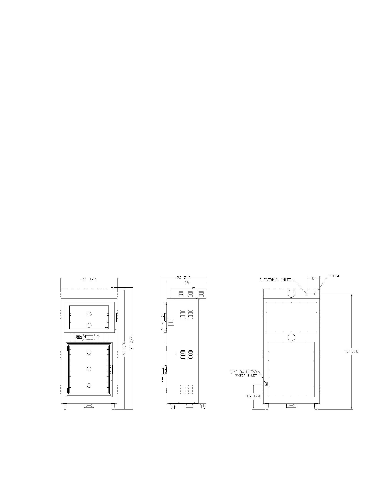
Measuring 77¾” high, 36½” wide and 28 5/8” deep, the entire unit takes up less than 7½ square feet of
floor space. It is constructed of stainless steel both inside and out. The front and back frames are cut from
single sheets of stainless steel. These frames then are welded to the stainless base and top headers to form
a unit with superior durability and rigidity. Components such as temperature and humidity controls,
timers, switches, motors, heating elements, and others are thoroughly tested before shipment. Ongoing
research and development projects are used to introduce the latest and most dependable components.
The NU-VU® SUB-123P is designed for:
• Automatic pan positioning • Dependability
• Rapid and even baking • Low energy consumption
• Easy cleaning • Low maintenance
• Simple operation • Rapid servicing
The AUTOMIST option eliminates the manually filled water pan in the proofer, but requires connection to a
pressurized potable water supply. An adjustable water mist is injected into the blower wheel in the bottom
of the proofer. The blower wheel then distributes this water mist evenly throughout the proofer
compartment to provide the controlled humidity necessary for proper proofing action.
NU-VU® FOOD SERVICE SYSTEMS MENOMINEE MICHIGAN 49858-1029
(906) 863-4401 Sales Fax (906) 863-5889 ♦ Service Fax (906) 863-6322 page 1
Page 10
ABOUT YOUR SUB-123P SUB-123P OWNER’S MANUAL
SUB-123P SPECIFICATIONS:
Exterior Dimensions
Height = 77¾" Width = 36½" Depth = 28 5/8”
Interior Dimensions (usable space)
Oven Height = 14½" Width = 26" Depth = 18½"
Proofer Height = 32" Width = 26" Depth = 18½"
Door Swing (straight out from face of unit)
Oven = 34 3/8" Proofer = 29 1/2"
Capacities
Oven = Six 13"x18" half size sheet pans with 4¼" pan spacing
or three 18"x26" full size sheet pans with 4½" spacing
Proofer = Eighteen 13"x18" half size sheet pans with 3¼" pan spacing
or nine 18"x26" full size sheet pans with 3¼" spacing
Listings/Approvals
Service Connections
Electrical:
120/208 volt, 60 Hz 120/240 volt, 60 Hz
Single or three phase, with an electrical neutral, to be hard wired on site.
The oven compartment uses two 2,000-watt heating elements in 208 or 240 volts.
The proofer compartment for the standard AUTOMIST proofer use two 600-watt heating
elements only; no humidity element is required.
Water:
Standard AUTOMIST units require direct connection to a pressurized potable water supply.
Any unit requiring connection to a water supply comes equipped with a 1/4” compression-type
copper fitting installed on the back of the unit (refer to Fig. #1 on page 3)
NU-VU® FOOD SERVICE SYSTEMS MENOMINEE, MICHIGAN 49858-1029
page 2 Sales Fax (906) 863-5889 ♦ Service Fax (906) 863-6322 (906) 863-4401
Page 11
SUB–123P OWNER'S MANUAL RECEIPT, INSTALLATION AND START-UP
Fig. #1 - Installation
RECEIPT, INSTALLATION AND START-UP
RECEIPT:
It is essential to inspect the unit immediately when it arrives. NU-VU® has placed instructions on the
packaging to help avoid damage in transit. However, negligent handling can produce hidden damage.
These steps should be followed:
A. Inspect the entire perimeter of the package for damage or punctures to the packing material.
This may indicate damage to the unit inside. Call any and all packing damage to the attention of
the delivery person.
B. If any package damage is found uncrate the unit immediately in the presence of the delivery
person to determine if the unit is damaged. Pay special attention to the top of the unit. Make sure
it is not bent or otherwise damaged, which may occur if the top of the unit has struck a door frame
or the top of a trailer. If any damage is found indicate the type and amount of damage on the
shipping documents and notify NU-VU® at (906) 863-4401 immediately after filing a freight
claim.
C. Uncrate the unit carefully and check the entire unit (top, front, back, and both sides) for any
visible or hidden damage.
D. Remove the unit from the shipping pallet and inspect the bottom (including the Casters) for any
damage. Check the Casters and the Proofer Motor/Cover under the unit.
E. If any damage is noted after the driver leaves immediately contact the freight company and
NU-VU® Food Service Systems.
F. Check the Oven and Proofer Doors. Make sure both Doors close completely, and that the Door
Gaskets seal firmly (refer to the DOOR TEST PROCEDURE in the SERVICE AND
REPLACEMENT GUIDE). If they do not close or seal properly please contact the NU-VU®
Service Department for instructions and assistance in any required adjustments.
G. Count the number of Shelves included. There should be a total of twelve (12) Shelves (nine for
the Proofer, three for the Oven). Contact NU-VU® immediately concerning any shortage.
NU-VU® FOOD SERVICE SYSTEMS MENOMINEE MICHIGAN 49858-1029
(906) 863-4401 Sales Fax (906) 863-5889 ♦ Service Fax (906) 863-6322 page 3
Page 12

RECEIPT, INSTALLATION AND START-UP SUB-123P OWNER’S MANUAL
IMPORTANT: DO NOT CONNECT THIS UNIT IF YOUR POWER SOURCE DOES NOT
MATCH THE REQUIREMENTS AS LISTED ON THE UNIT LABEL!
WARNING: ALL POWER MUST BE TURNED OFF AT THE ELECTRICAL SUPPLY WHILE
THIS UNIT IS BEING CONNECTED!
IMPORTANT: IN A THREE PHASE SYSTEM ANY WILD LEG (MORE THAN 120 VOLTS
TO NEUTRAL) MUST ALWAYS BE CONNECTED TO L-2!
INSTALLATION:
Record the Model Number and complete Serial Number of your unit in the spaces provided on page 27 of
this manual. You will need these numbers if you should ever need to contact our Service Department
concerning adjustments, replacement parts or other service needs.
Roll the unit into the exact position where it is to be operated. Make sure there will be enough clearance on
each side of the unit for proper cooling during operation, and for ease of access during maintenance or
service. NU-VU® recommends a minimum clearance of 4" at the back and both sides of the unit. Mark the
locations of the electrical and optional water connections on the wall.
Check the swing of both the Oven and Proofer Doors, making sure they have enough room to open
completely without hitting anything or obstructing the work area.
Move the unit out from its operating position and proceed with the service connections.
Connection of Electrical Supply - -
Check to determine that the power source is the same voltage and phase as that indicated on the label on the
side of the unit. If the voltage or phase is not the same, please call NU-VU® service department at (906)
863-4401.
This equipment must be installed and connected in accordance with all applicable federal, state, province,
and/or local electrical codes having jurisdiction. All electrical connections must be made with COPPER
WIRE ONLY in the correct gauge for the application. The unit may be connected either through a plug and
receptacle-type connection or direct wiring. Allow enough slack in the wiring to allow for equipment to be
moved during installation or any required maintenance and servicing.
The electrician should remove the Outside Top [71] to expose the power supply connections at the Power
Terminal Block [1] on top of the oven compartment. A wiring schematic is attached to the wiring near
the power terminal connections.
Proper electrical connections will vary depending on the voltage, phase and frequency requirements of the
unit and available power supply. The following instructions are for the most common 120/208 volt or
120/240 volt configurations (refer to Fig. #2 on page 5), and may be modified to fit your installation.
A. The electrician must install a cable clamping device or cord restraint in the rear access hole. This
cable clamping device must be firmly attached to the unit, and appropriately sized for the power
supply wire or cord being used.
B. Take note of the labeling on the Oven terminal connections (Line 1, Line 2, Line 3, and Neutral)
at the Power Terminal Block [1].
C. Carefully identify the power source connections and attach them to the appropriate terminals. Make sure
all connections are clean and tight.
D. Be sure the unit is properly grounded BEFORE use by attaching a grounding wire to the Ground
Lug [2] next to the Power Terminal Block.
NU-VU® FOOD SERVICE SYSTEMS MENOMINEE, MICHIGAN 49858-1029
page 4 Sales Fax (906) 863-5889 ♦ Service Fax (906) 863-6322 (906) 863-4401
Page 13

SUB–123P OWNER'S MANUAL RECEIPT, INSTALLATION AND START-UP
Fig. #2 – Power Supply Connections
Fig. #2 – Power Supply Connections
E. Engage the main power supply.
F. Check the voltage at the terminals on the Power Terminal Block with a voltmeter and compare the
readings with the label listings on the side of the unit. If the readings match, the unit is ready for
its initial START-UP. If the readings DO NOT coincide you must call the NU-VU® Service
Department.
G. Install any required or desired drain plumbing to the drain fitting in the base of the unit directly
under the proofer compartment.
H. Replace the Outside Top. Be careful not to pull or pinch any wires while installing the Panel.
I. Install nine of the supplied Shelves [65] in the Proofer. The other Shelves are used in the Oven.
J. Push the unit back into place and set the brakes on the front Casters.
K. The Proofer compartment of the NU-VU® SUB-123P is equipped with a bottom drain centered
directly under the Proofer Door. Please install the included Drain Pan [77] in the brackets under
the Proofer if you have not already installed drain plumbing. This drain prevents the build-up of
excessive water that may damage the Proofer Motor, Heating Element, or a Sensor.
Connection of Water Supply - -
This equipment must be installed in accordance with all applicable federal, state, province, and/or local
plumbing codes having jurisdiction.
NU-VU® strongly recommends that SOFT WATER ONLY be used in any unit requiring a water supply.
Also, a good quality water filter must be installed in-line between the unit connection and the water supply
to guard against clogging and mineral build-up in the components. This is extremely important in areas
having hard water. The water filter may be installed at the water source, adjacent to the water inlet on the
unit, or anywhere in between, whichever is more convenient for you.
A. Run 1/4” OD tubing from the water supply line to the unit location. Allow some slack in the
tubing for final unit positioning and any future service requirements. Avoid any kinks or strains
on the tubing, and position the tubing where it will not be damaged in any way.
B. The tubing end that attaches to the back of the unit must not be damaged or deformed in any way.
The cut end should be cut straight and clean with no deforming of the tubing. All burrs and sharp
or rough edges should be removed to ensure a proper and leak-free connection.
C. Position the tubing so that it runs straight into the intake Water Fitting [76] on the rear of the unit.
Be careful not to kink the tubing if you bend it, and do not bend the tubing within two (2) inches
of the cut end.
D. The two-part compression fitting (tapered collar and nut) is placed approximately 1” onto the end
of the tubing so that the collar is inside of the nut and the threaded opening of the nut is toward
the intake Water Fitting.
NU-VU® FOOD SERVICE SYSTEMS MENOMINEE MICHIGAN 49858-1029
(906) 863-4401 Sales Fax (906) 863-5889 ♦ Service Fax (906) 863-6322 page 5
Page 14

RECEIPT, INSTALLATION AND START-UP SUB-123P OWNER’S MANUAL
IMPORTANT: IMPROPER INSTALLATION, MISUSE, OR OTHER FAILURE TO FOLLOW
THESE INSTRUCTIONS MAY CAUSE SEVERE EQUIPMENT DAMAGE OR PERSONAL
®
E. Push the end of the tubing all the way into the intake Water Fitting (approximately 1/4”) and hold
it there while you thread the compression nut onto the intake Fitting. Tighten the compression nut
with an open-end wrench, but do not over-tighten the fitting! If the joint leaks when tested, and
further gently tightening does not stop the leakage, the compression fitting must be replaced.
Careful attention to these simple procedures will help to ensure an installation without leaks. If you have
any questions or problems, please call the NU-VU® Service Department at (906) 863-4401.
IMPORTANT: Please be sure to install any desired or required drain plumbing at this time. Any
required plumbing must be installed before attempting an INITIAL START-UP.
NOTE: Your SUB-123P is equipped with a Drain in the floor of the Proofer compartment. This Drain
prevents the accumulation of excess water that may damage the Proofer Motor, Heating Element or a
Control Sensor. Please slide the included Drain Pan [77] into the bracket under the Proofer Door to
catch any draining water, OR position the Proofer Drain directly over a floor drain, OR attach a
length of tubing or light hose to the Drain where it comes through the base of the unit and run it to a
floor drain in the immediate area.
YOUR NU-VU SUB-123P SHOULD NOW BE
READY FOR ITS INITIAL START-UP!
* * * Notice * * *
National Sanitation Foundation (NSF) guidelines require that all interior parts be removable
without the use of tools. This equipment has been factory assembled to safely
accommodate rough handling through shipment, delivery and original installation. After
any maintenance, cleaning or required service work the interior sheet metal parts should
be reassembled and fastened hand-tight only, but still be tight enough to prevent any rattle
or movement of parts.
START–UP:
Oven - - (refer to Fig. #3 on page 9)
A. Unscrew the glass Light Lenses [20] in the rear of the Oven. Install the included Appliance Bulbs
(if they are not already installed) and replace the Lenses. Close the Oven Door [41] securely.
B. Engage the main electrical and water supplies.
C. Press the Oven On / Off Button to turn on the Oven portion of the controls. Upon powering up the
Oven portion of the control, you will have the option of selecting the language you would like to
be displayed by pressing the enter button. After approximately 3 seconds Recipe 1 will be
automatically started. The controller is preprogrammed with Subway recommended baking time
and temperature settings. Recipe 1 is for bread and Recipe 2 is for cookies. You may need to
modify these settings for your location The interior of the Oven should illuminate and the Oven
Blower Wheel [7] should begin to rotate.
D. Open the Oven Door [41]. The Motor/Blower Wheel should come to a stop as the Door opens and
the Micro Switch [15] in the Door Jamb is released.
E. Place two empty sheet pans on the top and middle oven shelves and place a reliable oven
thermometer in the center of the middle shelf in the Oven.
NU-VU® FOOD SERVICE SYSTEMS MENOMINEE, MICHIGAN 49858-1029
page 6 Sales Fax (906) 863-5889 ♦ Service Fax (906) 863-6322 (906) 863-4401
Page 15

SUB–123P OWNER'S MANUAL RECEIPT, INSTALLATION AND START-UP
F. Close the Oven Door securely. The Motor/Blower Wheel should restart.
G. The Oven will begin heating to the Oven temperature set point. You may continue with the Oven Start-
Up and even begin the Proofer Start-Up while the Oven heats.
H. Press the Oven Start / Stop Button to begin the countdown timer. When the Oven time display reaches
zero the Alarm [16] will sound. Before pressing the Oven Start / Stop button to silence the Alarm [16],
you may want to adjust the volume baffle on the front of the alarm to the desired volume.
I. Check the thermometer reading against the Oven Actual Display when the Oven Ready light comes on.
The Alarm will sound to alert when the oven has reached the set point. If the readings differ by more
than 10 the Temperature Control may need a simple adjustment. Please call the NU-VU® Service
Department BEFORE attempting calibration or adjustment of the control.
NOTE: Please allow the Temperature Control to cycle two or three times to allow the Oven
temperature to stabilize BEFORE comparing the readings.
J.
Press the Oven On / Off Button to turn off the oven portion of the controller.
Standard AUTOMIST Proofer - - (refer to Fig. #3 on page 9)
A. Unscrew the glass Light Lenses [20] in the rear of the Proofer. Install the included Appliance
Bulbs (if they are not already installed) and replace the Lenses. Close the Proofer Door [42]
securely.
B. Press the Proofer On / Off Button to turn on the Proofer portion of the controls. Upon powering
up the Proofer portion of the control, Recipe 1 will be automatically started. The controller is
preprogrammed with Subway recommended Proofing time, temperature, and humidity settings.
You may need to modify these settings for your location. The Proofer interior should illuminate
and the Blower Wheel [11] should begin to rotate.
C. A light water mist will be sprayed from the Injection Nozzle [67] into the Blower Wheel [11].
The spray should stop after one second. After a short pause (approximately 20 seconds) the
Humidity Control and Injection Nozzle will cycle again. Set the Humidity Control to OFF.
D. The Proofer will begin heating when a recipe is loaded.
E. Place a reliable oven thermometer on a Proofer Shelf [65] in the center of the Proofer.
F. When the Proofer Temperature set point is reached the Alarm [16] will sound. Check the
thermometer reading against the Proofer Actual Temperature on the controller (refer to the
Programmable Controller section of this manual if you are unsure of how to do this). If the
readings differ by more than 5 the Temperature Control may need a simple adjustment. Please
call the NU-VU® Service Department BEFORE attempting calibration or adjustment of the
control.
NOTE: Please allow the Temperature Control to cycle two or three times to allow the Proofer
temperature to stabilize BEFORE comparing the readings.
G. Press the Proofer On / Off Button to turn off the Proofer portion of the controller.
Your AUTOMIST SUB-123P is now ready to operate!
NU-VU® FOOD SERVICE SYSTEMS MENOMINEE MICHIGAN 49858-1029
(906) 863-4401 Sales Fax (906) 863-5889 ♦ Service Fax (906) 863-6322 page 7
Page 16

OPERATING INSTRUCTIONS SUB–123P OWNER'S MANUAL
IMPORTANT: ALWAYS REDUCE THE HUMIDITY SETTING TO OFF WHEN OPERATING
THE PROOFER FOR EXTENDED PERIODS WITHOUT ANY PRODUCT INSIDE!
Fig. #3 –Oven & Proofer Controls
OPERATING INSTRUCTIONS
PROOFER:
For the Standard AUTOMIST Proofer - -
Begin to pre-heat the Proofer section of the SUB-123P about 20 to 30 minutes before its scheduled use.
A. Set out the desired product for thawing. Be sure to allow sufficient time in your schedule for both the
product and your equipment to reach the correct conditions.
B. Prepare the Proofer:
1. Press the Proofer On / Off Button to turn on the Proofer portion of the controls. Upon powering up
the Proofer portion of the control, Recipe 1 will be automatically started. The controller is
preprogrammed with Subway recommended Proofing time, temperature, and humidity settings. You
may need to modify these settings for your location.
2. Make sure water is being supplied to the Proofer. An AUTOMIST unit injects water directly into the
air in the Proofer, raising the internal humidity level almost immediately.
3. The Proofer is ready for use when the Proofer Ready Light comes on and a light to moderate fogging
C. Load the product. The pans should be pushed all the way back and centered from side to side as much as
D. Press the Proofer Start / Stop to begin the countdown timer as a reminder to check your proof.
F. Monitor the proofing process. Your Proofer is functioning properly if there is a light to moderate fogging
appears on the Proofer Door [42].
possible on each Proofer Shelf to allow for proper air circulation over and around your product. If you are
loading a single pan, center it on the Shelf from side to side and front to back.
on the Proofer Door. No fogging means your Proofer may be running too hot, too dry, or both. Excessive
fogging (with water running down the glass) means your Proofer may be running too cold, too wet, or
both. Check the product and adjust the Proofer Temperature and Humidity Controls as necessary.
NU-VU® FOOD SERVICE SYSTEMS MENOMINEE, MICHIGAN 49858-1029
page 8 Sales Fax (906) 863-5889 ♦ Service Fax (906) 863-6322 (906) 863-4401
Page 17

SUB–123P OWNER'S MANUAL OPERATING INSTRUCTIONS
WARNING: WE TRY TO “BURN OFF” ANY MANUFACTURING OILS INSIDE OF YOUR
OVEN BEFORE SHIPMENT. HOWEVER, SOME OILS MAY REMAIN, CAUSING YOUR
OVEN TO SMOKE DURING INITIAL OPERATION. SIMPLY ALLOW THE OVEN TO RUN
AT 350°F FOR AN HOUR OR TWO TO COMPLETE THE BURN-OFF AND THE SMOKING
SHOULD STOP. WE APOLOGIZE FOR ANY INCONVENIENCE THIS MAY CAUSE.
CAUTION: STAND AWAY FROM THE FRONT OF THE OVEN WHEN OPENING THE
OVEN DOOR AFTER A BAKING CYCLE TO AVOID EXPOSURE TO HEAT AND STEAM!
TIP: If water accumulates on the floor in front of your Proofer from drippings out of the Proofer Door you
are probably proofing with too much humidity. Decrease the Humidity Control setting. If water on the
floor is a constant problem for you please call the NU-VU® Service Department at (906) 863-4401.
G. Load the Oven when your product is fully proofed. Yeast products should be 65% to 75% of the desired
finished size at the end of the proof cycle. Generally speaking, properly proofed bread should have a soft,
silky smooth feel to it when touched. It should never be anything more than slightly tacky. If the dough
sticks to your finger and does not pull off cleanly, the dough is too wet.
OVEN:
Since your Oven requires time to reach the proper temperature, you must plan ahead so your Oven and product are
ready at the same time. When the desired temperature is reached (about 15-20 minutes after start-up), the Oven
Ready Light will come on.
To operate the Oven section:
A. Press the Oven On / Off Button to turn on the Oven portion of the controls. Upon powering up the Oven
portion of the control, you will have the option of selecting the language you would like to be displayed by
pressing the enter button, after approximately 3 seconds Recipe 1 will be automatically started. The
controller is preprogrammed with Subway recommended baking time and temperature settings. Recipe 1 is
for bread and Recipe 2 is for cookies. You may need to modify these settings for your location. When the
Oven Ready Light comes on the Oven is ready for baking.
B. Load the Oven from the top down, placing a single full size pan or two half-size pans on each Shelf. Push
the pans all the way to the rear, and center them from side to side. Single pans should be centered from
side to side and front to back. If the top shelf is too high to be reached safely and easily, empty pans should
be placed on the shelf to guide the air flow over and around your product for the best possible results.
C. Close the Oven Door [41] securely. It is important to keep the Oven Door closed unless loading or
removing product to maintain Oven temperature, reduce baking time, and minimize energy usage.
NOTE: It is helpful to slowly push the Oven Door closed until the Oven Motor restarts. Hold it about 1"
from the closed position for only 1 or 2 seconds before latching it securely. This short delay prevents the
build-up of internal air pressure that may suddenly "pop" the Oven Door open.
D. Press the Oven Start / Stop Button to start the count-down timer. The alarm will sound when the timer
has reached zero.
E. As soon as the product is finished baking, open the Oven Door and remove the product quickly. You
can load more product into the Oven immediately, or close the Oven Door and allow the Oven to recover
to the set baking temperature. Allowing the Oven a few minutes of recovery time results in a quicker and
better bake.
F. When all baking is done for the day, set both the Temperature Control and the Power Switch to OFF and
complete the daily DRY-OUT PROCEDURE outlined in the MAINTENANCE AND CLEANING GUIDE.
NU-VU® FOOD SERVICE SYSTEMS MENOMINEE MICHIGAN 49858-1029
(906) 863-4401 Sales Fax (906) 863-5889 ♦ Service Fax (906) 863-6322 page 9
Page 18

PROGAMMABLE CONTROLLER SUB–123P OWNER'S MANUAL
PROGRAMMABLE CONTROLLER
To turn on the controller, simply press either of the power buttons. The arrow points to the proofer power button.
To turn on the oven portion of the controller, press the oven power button. The arrow points to the oven power button.
The oven and proofer portions of the controller can be turned on and off independently. Upon turning on the oven
portion of the controller, you will have the option of selecting the language you would like to be displayed by
pressing the enter button. After approximately 3 seconds of not pressing any buttons, the oven portion will turn on.
When the controller is turned on it will begin heating to the current set points (oven temp, proofer temp & proofer
humidity).
NU-VU® FOOD SERVICE SYSTEMS MENOMINEE, MICHIGAN 49858-1029
page 10 Sales Fax (906) 863-5889 ♦ Service Fax (906) 863-6322 (906) 863-4401
Page 19

SUB–123P OWNER'S MANUAL PROGRAMMABLE CONTROLLER
When the actual oven temperature reaches the oven temperature set point the ready indicator light will remain on and an
alarm will sound briefly; signifying that the oven is now ready to be loaded with product.
After the product is loaded into the oven, the operator presses the start/stop button to start the countdown timer.
When the oven timer has reached zero, an audible alarm will sound to alert the operator that the baking cycle has
finished. The operator presses the start/stop button to stop the alarm and reset the countdown timer.
NU-VU® FOOD SERVICE SYSTEMS MENOMINEE MICHIGAN 49858-1029
(906) 863-4401 Sales Fax (906) 863-5889 ♦ Service Fax (906) 863-6322 page 11
Page 20

PROGAMMABLE CONTROLLER SUB–123P OWNER'S MANUAL
All of the set points can be adjusted using the buttons on the right hand side of the controller (up, down, left, right &
enter).
Using the arrow buttons the operator can scroll to any of the set points.
The actual proofer temperature can be viewed by scrolling to the temp line on the proofer side of the display and the
display line will toggle between the actual temp and the temp set point.
NU-VU® FOOD SERVICE SYSTEMS MENOMINEE, MICHIGAN 49858-1029
page 12 Sales Fax (906) 863-5889 ♦ Service Fax (906) 863-6322 (906) 863-4401
Page 21

SUB–123P OWNER'S MANUAL PROGRAMMABLE CONTROLLER
The humidity set point is displayed in % relative humidity.
The actual relative humidity can be viewed by scrolling to the humidity display line. The display line will toggle
between set point and actual humidity. A separate hygrometer is not necessary to ensure that the proper humidity level
is achieved. The controller uses an RH sensor to control the proofer temp and humidity level.
When the proofer temp and humidity set points are reached, the proofer ready indicator will remain on and an alarm
will sound briefly; signifying that the proofer is now ready to be loaded with product.
NU-VU® FOOD SERVICE SYSTEMS MENOMINEE MICHIGAN 49858-1029
(906) 863-4401 Sales Fax (906) 863-5889 ♦ Service Fax (906) 863-6322 page 13
Page 22

PROGAMMABLE CONTROLLER SUB–123P OWNER'S MANUAL
The buttons labeled 1, 2 & 3 will allow the operator to toggle between the three timers (T1, T2 & T3).
When T1 is displayed next to the time on the proofer side of the control, pressing the start / stop button will start Timer
#1.
Pressing button #2 will bring up timer #2 on the display.
NU-VU® FOOD SERVICE SYSTEMS MENOMINEE, MICHIGAN 49858-1029
page 14 Sales Fax (906) 863-5889 ♦ Service Fax (906) 863-6322 (906) 863-4401
Page 23

SUB–123P OWNER'S MANUAL PROGRAMMABLE CONTROLLER
When T2 is displayed next to the time on the proofer side of the control, pressing the start / stop button will start Timer
#2.
Pressing button #3 will bring up timer #3 on the display.
When T3 is displayed next to the time on the proofer side of the control, pressing the start / stop button will start Timer
#3.
NU-VU® FOOD SERVICE SYSTEMS MENOMINEE MICHIGAN 49858-1029
(906) 863-4401 Sales Fax (906) 863-5889 ♦ Service Fax (906) 863-6322 page 15
Page 24

PROGAMMABLE CONTROLLER SUB–123P OWNER'S MANUAL
The operator can select a different recipe by moving the cursors to the bottom line on the proofer side of the display.
Pressing the pressing the enter button will bring up recipes 1, 2 & 3.
Pressing the pressing the enter button again will bring up recipes 4, 5 & 6.
NU-VU® FOOD SERVICE SYSTEMS MENOMINEE, MICHIGAN 49858-1029
page 16 Sales Fax (906) 863-5889 ♦ Service Fax (906) 863-6322 (906) 863-4401
Page 25

SUB–123P OWNER'S MANUAL PROGRAMMABLE CONTROLLER
To edit the timer set point the operator would move the cursor to line three and press the enter button.
Now that the time set point is activated, the user can change the value using the directional button.
The controller uses one-touch recipe recall using the buttons located below the oven and proofer displays. A recipe can
also be saved using these buttons. To save the current settings to a recipe slot the operator would hold the button
(beneath the display number) for five seconds, a beep will sound when the recipe has been saved. The save function can
be locked to prevent tampering. Note: The proofer display must show the recipe number in order to save the settings.
NU-VU® FOOD SERVICE SYSTEMS MENOMINEE MICHIGAN 49858-1029
(906) 863-4401 Sales Fax (906) 863-5889 ♦ Service Fax (906) 863-6322 page 17
Page 26

PROGAMMABLE CONTROLLER SUB–123P OWNER'S MANUAL
An arrow will appear next to the number (on the display) of the currently loaded recipe.
The arrow buttons are used to edit all of the set points. The left and right arrows will shift the cursors between the oven
and proofer sides of the display.
NU-VU® FOOD SERVICE SYSTEMS MENOMINEE, MICHIGAN 49858-1029
page 18 Sales Fax (906) 863-5889 ♦ Service Fax (906) 863-6322 (906) 863-4401
Page 27

SUB–123P OWNER'S MANUAL MAINTENANCE AND CLEANING GUIDE
IMPORTANT: THESE DRY-OUT PROCEDURES MUST BE CARRIED OUT DAILY TO HELP
MAINTAIN YOUR EQUIPMENT IN THE BEST POSSIBLE CONDITION. THE REMOVAL OF
RESIDUAL MOISTURE HELPS PREVENT DETERIORATION OF THE INSULATION, DAMAGE
TO THE PROOFER ELEMENTS, SENSORS, MOTOR AND OTHER ELECTRICAL
COMPONENTS, AND EXTENDS THE USEFUL LIFETIME OF YOUR NU-VU® EQUIPMENT!
MAINTENANCE AND CLEANING GUIDE
MAINTENANCE:
NU-VU® equipment is designed to last for years of useful service. Careful consideration is given in
selecting components for durability, performance and ease of maintenance. For example, both the Oven
Motor and Proofer Motor have sealed bearings and never need to be lubricated.
While NU-VU® equipment is designed for minimum care and maintenance; certain steps are required by the
user for maximum equipment life and effectiveness:
Proper installation of the equipment.
Correct application and usage of the equipment.
Dry-out Procedures performed daily.
Thorough cleaning on a regular basis.
AUTOMIST Proofer Dry-Out Procedure - -
A. The Programmable Controller [4] has a proofer dry-function incorporated for your convenience.
Upon pressing the proofer power button to turn off the proofer, you will be prompted as to
weather or not to run the dry-out procedure. At this point the elements and proofer fan will be off.
Pressing the proofer power button again will cancel the dry-out procedure, although it is
recommended that the dry-out procedure be preformed any time the proofer will be off for more
than a few hours.
Use caution when wiping near the Heating Elements [9] as they may still be warm.
B. Wipe out any standing water in the bottom of the Proofer. You will need to remove the Element
Cover [60] to do this. This is also a good time to remove and clean the Humidity Nozzle [67a].
C. Press the Enter button on the control, doing so will run the Controller’s dry-out function. The
proofer elements will turn on for 20 minutes to dry-out any remaining moisture, during this time
the Proofer Door [42] should be left open 1 to 2 inches.
D. Empty, clean, and replace the Drain Pan [77] beneath the Proofer.
E. After the 20 minutes, the proofer portion of the control will automatically turn off. Re-install the
Humidity Nozzle [67a] and Element Cover [60] if you have not done so already.
Oven Dry-Out Procedure - -
A. Turn off the Oven portion of the Programmable Controller [4].
B. Leave the Oven Door [41] open about 1 to 2 inches. The residual baking heat will dry out any
moisture that may be trapped in the insulation or other components of the Oven.
C. Leave the Oven Door slightly open (about 1 to 2 inches) while the Oven is not in use.
D. The Cooling Fan [19] will continue to run for approximately 5 minutes after both the Oven and
Proofer portions of the Programmable Controller [4] are turned off.
NU-VU® FOOD SERVICE SYSTEMS MENOMINEE MICHIGAN 49858-1029
(906) 863-4401 Sales Fax (906) 863-5889 ♦ Service Fax (906) 863-6322 page 19
Page 28

MAINTENANCE AND CLEANING GUIDE SUB–123P OWNER'S MANUAL
CLEANING:
Your SUB-123P should be cleaned daily and as soon as possible after a spill has occurred. It is essential to
maintain a clean unit, especially if the public views the unit in your place of business. The following should
be used for cleaning:
A. The stainless steel exterior may be cleaned with any good stainless steel cleaner or polish, or with
hot soapy water followed by a clear rinse if it is very soiled.
B. The Doors can be removed for ease of cleaning by opening each Door until it is perpendicular to
the face of the unit and then lifting the Door straight up. All glass should be cleaned with a glasscleaning formula. Baked-on or excessive soiling can be removed with soap and hot water
followed by a thorough rinse with fresh clean water. Severe deposits may be loosened and
removed by soaking in a stronger soap and water solution.
C. The Oven and Proofer interiors (including the Door Jamb) should be cleaned on a regular basis
with mild soap and hot water followed by a thorough rinse with fresh clean water.
WARNING: Do not use oven cleaners in the Oven! Once in the side walls these cleaners are very
difficult to remove, and may cause your oven to smoke or emit noxious fumes until they are rinsed
out or burned away. You will need to completely disassemble the oven interior in order to flush
out any remaining oven cleaner
D. The Proofer Element Cover should be removed on a regular basis when cleaning the interior of
the Proofer. Clean the Element Cover with mild soap and hot water, rinse with clean fresh water,
and wipe dry to prevent spotting.
E. Proofers equipped with the AUTOMIST option should have the Water Injection Nozzle inspected
and cleaned at regular intervals as determined by usage and water hardness. To clean the Water
Injection Nozzle:
1. Remove the Proofer Element Cover to expose the bottom of the Proofer compartment.
2. Remove the nozzle by turning one quarter turn counter-clockwise after which the Nozzle can
be pulled out.
3. Soak all parts for 30 to 60 minutes in a small container of Lime-Away or other mild
commercial mineral remover. Carefully brush and rinse all three parts.
4. Install the Nozzle by aligning the flats on the Nozzle and Base, pushing the Nozzle until fully
seated in the Base and turning one quarter turn clockwise.
5. Replace the Element Cover.
* * * CAUTION * * *
NU-VU® DOES NOT RECOMMEND the use of any strong commercial or caustic product on this
equipment. DO NOT allow any type of caustic cleaner to come into contact with any aluminum parts (such
as Door Frames), the silicon rubber Door Gaskets, or any of the sealing compound in the Oven and Proofer
seams and joints. These compounds may cause discoloration and degradation of these parts resulting in
permanent damage. DO NOT use bleach or bleach compounds on any chromed parts; bleach will damage
chrome plating.
NOTE:
NU-VU® has had very good results with a product called JIFFY CLEANER. For standard cleaning simply
spray JIFFY on and wipe off. Heavily soiled areas may require a short period of soaking. This cleaner is
available through NU-VU® (Part #51-0002) or through your local Rochester/Midland distributor or
representative.
NU-VU® FOOD SERVICE SYSTEMS MENOMINEE, MICHIGAN 49858-1029
page 20 Sales Fax (906) 863-5889 ♦ Service Fax (906) 863-6322 (906) 863-4401
Page 29

SUB–123P OWNER'S MANUAL SERVICE AND REPLACEMENT GUIDE
SERVICE AND REPLACEMENT GUIDE
Your SUB-123P has been designed to be serviced quickly and easily. In fact, any individual who has
average mechanical ability can do the work. Our Service Department is also available to you Monday
through Friday from 7:00 a.m. to 5:00 p.m. (Central Standard Time) should you find yourself with a
situation or problem other than what is outlined here. Call NU-VU® at (906) 863-4401 and ask for our
Service Department to order replacement parts, ask questions, or offer comments.
This SERVICE AND REPLACEMENT GUIDE has been prepared to cover normal service problems. If this
"trouble-shooting" information does not provide a solution for your particular problem we ask that you call
us for direct assistance. Calling our Service Department before calling in a repair technician can usually
save you both time and unnecessary expense. We want to do everything we can to minimize your "downtime".
You may need to remove an Access Panel for servicing. DO NOT allow any Access Panels to drop. When
work on the component is finished replace the Panel with care, making sure that all wires are properly
placed and not pulled or pinched. If more than one component is being worked on try to remove only one
component at a time.
The Illustrations used throughout this OWNER'S MANUAL are numbered in their lower left-hand corners.
A complete listing of these Illustrations along with their page numbers can be found at the beginning of this
manual on page v.
A REPLACEMENT PARTS LIST can be found starting on page 28. These parts are listed by Reference
Number. The part Reference Numbers are circled in the illustrations and bracketed [ ] in the text. Please
note that some of the parts listed are not replaceable except as part of another assembly, but are listed for
reference and identification only.
Wiring schematics are included at the end of this OWNER'S MANUAL for reference only. Please contact
our Service Department at (906) 863-4401, for more detailed and current information.
* * * NOTICE * * *
NATIONAL SANITATION FOUNDATION (NSF) GUIDELINES REQUIRE THAT ALL INTERIOR
PARTS BE REMOVABLE WITHOUT THE USE OF TOOLS. THIS EQUIPMENT HAS BEEN
FACTORY ASSEMBLED TO SAFELY ACCOMMODATE ROUGH HANDLING THROUGH
SHIPMENT AND ORIGINAL INSTALLATION. AFTER ANY MAINTENANCE, CLEANING OR
REQUIRED SERVICE WORK THE INTERIOR SHEET–METAL PARTS SHOULD BE
REASSEMBLED AND FASTENED HAND–TIGHT ONLY, BUT STILL REMAIN TIGHT ENOUGH
TO PREVENT ANY RATTLE OR MOVEMENT OF PARTS.
NU-VU® FOOD SERVICE SYSTEMS MENOMINEE MICHIGAN 49858-1029
(906) 863-4401 Sales Fax (906) 863-5889 ♦ Service Fax (906) 863-6322 page 21
Page 30

SERVICE AND REPLACEMENT GUIDE SUB–123P OWNER'S MANUAL
Fig. #4 – Door Latch Assembly
DOOR LATCH, How To Adjust:
Determine if the Oven Door [41] or Proofer Door [42]
is fitting too loose (it will leak moisture and heated air
past the Gasket) or too tight (it will not close properly,
or will "pop" open unexpectedly). If it is too loose the
Door Latch [44] must be adjusted OUT (away from the
unit); if it is too tight the Door Latch must be adjusted
IN (towards the unit). Please proceed as follows:
A. Loosen the two acorn nuts inside the Latch Cover
[45] with a 3/8" box wrench. Pull the Latch Cover
straight out from the Door to remove it, and then
remove the acorn nuts.
B. Open the Door and take careful notice of the
adjustment plate position against the body of the
Door Latch.
C. Hold the adjustment plate against the body of the
Door Latch with one hand while you loosen the
three mounting screws with the other hand. Back
the screws out approximately three full turns.
D. CAREFULLY move the Door Latch body IN or
OUT under the adjustment plate one notch at a
time. Make sure the Door Latch stays straight up and down, and tighten the mounting screws.
Test the Door for proper closing and sealing (refer to the DOOR TEST PROCEDURE).
E. Repeat steps "C" and "D" if you are not satisfied with the Door adjustment. If the Door tests as
satisfactory make sure the three mounting screws are tightened securely.
F. Install the acorn nuts on the ends of the top and bottom Door Latch screws. Turn the nuts on all
the way until they just contact the back side of the latch bracket, then loosen them by 1½ to 2 full
turns. Install the Latch Cover and tighten the acorn nuts lightly to hold the Latch Cover in place.
DOOR TEST PROCEDURE:
A. Cut one or two strips of paper approximately 1" wide and 8" to 10" long.
B. Open the Door slightly, insert a strip of paper between the Gasket [46] and Door Jamb and close
the Door.
C. Slowly pull the paper strip out. You should feel some resistance as you pull the strip from
between the Gasket and Door Jamb of a properly adjusted Door. Test the fit at regular 2" to
3" intervals around the entire Door.
1. If you feel NO resistance at a particular spot the Door is too loose, you have found a weak or
damaged spot in the Door Gasket or the Door Jamb has been bent in.
2. If you feel HEAVY resistance at a particular spot the Door is too tight or the Door Jamb has
been bent out.
NU-VU® FOOD SERVICE SYSTEMS MENOMINEE, MICHIGAN 49858-1029
page 22 Sales Fax (906) 863-5889 ♦ Service Fax (906) 863-6322 (906) 863-4401
Page 31

SUB–123P OWNER'S MANUAL SERVICE AND REPLACEMENT GUIDE
IMPORTANT: DO NOT DISASSEMBLE THE DOOR FRAME WHEN REPAIRING OR
REPLACING THE DOOR GASKET!
IMPORTANT: DO NOT STRETCH OR PULL ON THE GASKET DURING THE
INSTALLATION PROCESS. THIS WILL LATER CAUSE THE TRIMMED CORNERS TO
SEPARATE AND PULL APART!
IMPORTANT: MAKE SURE THAT THE GASKET AND DOOR FRAME ARE BOTH
COMPLETELY CLEAN AND DRY BEFORE APPLYING ANY SEALANT!
Fig. #5 – Door Gasket
DOOR GASKET, How To Replace:
Follow these instructions to correctly and easily replace
your Door Gasket with minimal problems. If you have
any problems or questions please call the NU-VU®
Service Department at (906) 863-4401 Monday
through Friday from 7:00 a.m. until 5:00 p.m. for
assistance.
Replacing the Oven Door Gasket - -
A. Remove all pieces of the old Gasket. Thoroughly clean the Door frame in the area of the new
gasket installation. Remove any old sealant and any baked-on deposits.
B. Replacement Gasket for the Oven Door is supplied to you as a single length of high-temperature
material. This Gasket must be cut to lengths that slightly overlap the sides of the Door frame.
C. Put a small amount of soap water into and around the slot that the new Gasket will fit into (a small
trigger spray bottle works well). This step is optional but will help in the installation.
D. Position the new Gasket over the slot, allowing the ends to extend past the end of the slot. Press
the mounting flange down into the slot on the Door frame. Use a roller tool to force the mounting
flange into the slot by working the tool back and forth along the Gasket. Make sure the Gasket
mounting flange is completely fitted into the slot and that the Gasket is free to slide back and forth
in the slot.
E. Use a sharp knife or a single-edged razor blade to cut the ends of the Gasket at a 45 angle (you
can use the mitered corner joint on the Door as an angle guide). Cut the Gasket about 1/4" longer
than the required length and work the excess back into the slot. This extra Gasket will help to
create a nice tight corner joint, and allows for any follow-up trimming that may be necessary.
F. Work your way around the entire Door (or the section of the Door having the Gasket replaced).
Make sure the Gasket is just tight into the corners. A bulging joint or pucker along the Gasket
indicates a Gasket section that is cut too long. Joints that pull apart indicate that one or more
gasket sections are cut too short.
G. Seal the corner joints after the entire Gasket is properly fitted. Pull the joints apart only enough to
put sealant on all of the cut edges only. Allow the Gasket joint to come together. Smooth out any
excess sealant to form a smooth surface on the face of the Gasket. Add more sealant to any spots
as necessary and smooth them down.
NU-VU® FOOD SERVICE SYSTEMS MENOMINEE MICHIGAN 49858-1029
(906) 863-4401 Sales Fax (906) 863-5889 ♦ Service Fax (906) 863-6322 page 23
Page 32

SERVICE AND REPLACEMENT GUIDE SUB–123P OWNER'S MANUAL
WARNING: SOME SEALANTS GIVE OFF ACIDIC FUMES AS THEY CURE. THESE
FUMES MAY CAUSE IRRITATION TO THE EYES AND/OR NASAL PASSAGES. USE
CAUTION WHEN OPENING YOUR UNIT AFTER WAITING FOR ANY FRESH SEALANT
TO SET UP AND CURE!
H. A quality sealant will be dry to the touch and tack-free in one to two hours after application.
However, it will not be completely cured until six to eight hours later. We recommend that you
wait until after your sealant is completely cured before using your Oven.
Replacing the Proofer Door Gasket - -
A. Remove all pieces of the old Gasket. Thoroughly clean the Door frame in preparation for the new
installation. Remove any old sealant, bits of Gasket and baked-on deposits.
B. The replacement Proofer Door Gasket is supplied as a single formed piece of low-temperature
material. This material is not suited for use in a high-temperature application, and should never be
used on an Oven Door.
C. Place the formed Gasket over the slot in the face of the Door frame and press it firmly into place.
A small roller tool will aid in fully seating the Gasket in the mounting slot.
D. The replacement Gasket requires nothing further. You may begin using your Proofer as soon as
the Gasket has been installed.
NU-VU® FOOD SERVICE SYSTEMS MENOMINEE, MICHIGAN 49858-1029
page 24 Sales Fax (906) 863-5889 ♦ Service Fax (906) 863-6322 (906) 863-4401
Page 33

SUB–123P OWNER'S MANUAL NU-VU EQIPEMENT WARRANTY
NU-VU® EQUIPMENT WARRANTY
NU-VU® products are warranted against defects in workmanship and materials from the original date of
shipment only. NU-VU® does not warrant against any damage that may occur during shipment or storage of
the equipment. Any claim for such damage must be filed against the carrier or storage company. No other
express warranty, written or oral, applies. No person is authorized to give any other warranty or assume any
other liability on behalf of NU-VU®, except by written statement from an officer of NU-VU®.
Your NU-VU® equipment warranty is limited to the following time periods for the original owner only:
PARTS LABOR
Inside the United States 24 Months 12 Months
All areas outside the United States 12 Months 12 Months
These time limits will apply in all cases unless prior arrangements have been made and agreed to in writing.
The NU-VU® equipment warranty is composed of the following:
PARTS:
This limited warranty covers certain electrical, electronic and mechanical parts for the time periods shown
above with the exception of those items detailed under Warranty Limitations. Customers who maintain an
open account may purchase against their account. MasterCard, Visa and American Express credit cards are
also accepted.
The return of defective parts is required. The return of a defective part or component must be made prior to
the issuance of a credit on an open account. If a part that is returned tests satisfactory in the NU-VU® factory
or at an authorized NU-VU® dealer or service agency, NU-VU® may withhold issuing credit. Replacement
parts will be warranted for a period of ninety (90) days provided they are installed and used in a manner
authorized by NU-VU®.
LABOR:
We require that you call our NU-VU® Service Department at (906) 863-4401 for service authorization
BEFORE you call any service agency if you wish to claim a labor expense under this warranty. We may be
able to solve your problem over the telephone, or we will schedule a warranty service call by a reliable
service agency in your area.
This warranty covers the replacement and installation of parts and components which are included under
PARTS for the time period listed above. This coverage is limited to the normal mileage allowance for a
maximum travel radius of up to fifty (50) miles, and the normal labor rate times the allowable hours for
performing the work as set forth in the following listing:
STANDARD TIME ALLOWANCES FOR WARRANTY REPLACEMENTS
Change performed Change time Test time Total time
Oven Heating Element 1 hr. ½ hr. 1½ hr.
Oven Motor/Rebalance Fan 1 hr. ½ hr. 1½ hr.
Programmable Controller ½ hr. ½ hr. 1 hr.
Control Sensor ½ hr. ½ hr. 1 hr.
Proofer Heating Element ½ hr. ½ hr. 1 hr.
Contactor ½ hr. 5 min. ½ hr.
Proofer Motor ½ hr. 5 min. ½ hr.
NU-VU® FOOD SERVICE SYSTEMS MENOMINEE MICHIGAN 49858-1029
(906) 863-4401 Sales Fax (906) 863-5889 ♦ Service Fax (906) 863-6322 page 25
Page 34

NU-VU EQIPEMENT WARRANTY SUB–123P OWNER'S MANUAL
IMPORTANT: NU-VU WILL NOT PAY FOR ANY SERVICE CALLS AS WARRANTY
WORK IF A NU-VU® AUTHORIZED SERVICE AGENCY DETERMINES THAT YOUR
EQUIPMENT IS SET UP AND OPERATING PROPERLY!
These times are based on servicing a unit that has been installed with allowance made for Access Panels on
the unit. If the unit is built into a wall that makes servicing very difficult or impossible without removing
part of the counter, wall, trim, etc., the extra time for gaining access shall be charged to the owner of the
unit. NU-VU® has determined that the listed times, which are based on the period necessary for a trained
service person to perform the work noted, are fair and reasonable. If a problem is not diagnosed within a
half-hour, the service person must contact the NU-VU® Service Department via telephone. Additional time
for problem solving will not be allowed unless this procedure is followed. An appointment for servicing a
unit should be set up since time will not be allowed for waiting to service a unit. Unless the service person
justifies extra time for performing the work noted, charges for work performed by the service person in
excess of the allowed time shall either be billed to the owner of the equipment or denied.
WARRANTY LIMITATIONS:
NU-VU® will pay for parts and labor under warranty if there is a defective component, but not for:
Normal operational wear and tear on the following parts -
Light bulbs
Door gaskets
Door handles and catches
Fuses
Damage attributable to customer abuse, including -
Proofer water pan allowed to run dry and burn.
Proofer fan motor damaged from not following outlined Dry-Out Procedure.
Lack of regular cleaning or maintenance.
Power supply problems, including -
Insufficient or incorrect voltage.
Damage to electrical components caused by a power surge or spike.
Incorrect installation (i.e., equipment not supplied with separate neutral or ground as required,
or incorrect location of high-voltage power leg for 240-volt 3-phase units).
Damage to electrical components resulting from use of an incorrect power supply cord or
circuit breaker.
Operational problems resulting from customer’s failure to follow established procedures outlined in
the Owner’s Manual.
A service call if nothing is found to be wrong (any returned parts work as per spec when tested).
Recalibration of temperature and humidity controls (all controls are carefully calibrated and tested
at our facility before shipment).
Any equipment moved from the place of original installation unless NU-VU
continue the warranty after the relocation.
Ongoing operational adjustments due to changing environmental conditions or normal wear and
tear.
Any overtime charges. NU-VU
equipment.
®
will pay straight time only for any work performed on NU-VU
®
agrees in writing to
®
NU-VU® FOOD SERVICE SYSTEMS MENOMINEE, MICHIGAN 49858-1029
page 26 Sales Fax (906) 863-5889 ♦ Service Fax (906) 863-6322 (906) 863-4401
Page 35

SUB–123P OWNER'S MANUAL NU-VU EQIPEMENT WARRANTY
Please use this space to record the Model Number and complete 12-digit Serial Number from the
nameplate on the side of your NU-VU® equipment. You will need both of these numbers if you ever
need to contact our Service Department concerning adjustments, replacement parts or other service.
Model Number: S U B - 1 2 3 P
Serial Number: ___ ___ ___ ___ ___ ___ ___ ___ ___ ___ ___ ___
Products must be installed and maintained in accordance with NU-VU® instructions. Users are responsible
for the suitability of the products to their application. There is no warranty against damage resulting from
accident, abuse, alteration, misapplication, inadequate storage prior to installation, or improper specification
or other operating conditions beyond our immediate control. Claims against carrier damage in transit must
be filed by the buyer; therefore, the buyer must inspect the product immediately upon receipt.
THIS WARRANTY DOES NOT COVER ADJUSTMENTS
DUE TO NORMAL ON-GOING USE OF THE UNIT!!!
PARTS RETURN PROCEDURE AND CONDITIONS:
The following procedure shall be followed for the return of parts to the factory for credit consideration:
All parts received by NU-VU
®
must have a completed RETURN AUTHORIZATION FORM as
supplied by NU-VU® with the replacement part.
Package all return parts securely so that in-transit damage cannot occur.
Prepay shipment. Any parts returned collect will be refused by our receiving department. Credit will
be considered on proper returns only.
As soon as parts are tested and confirmed to be defective credit will be issued against them.
If the engineering test shows the component is not defective and is in good working condition it
may be returned to you along with your request for payment.
NU-VU® FOOD SERVICE SYSTEMS MENOMINEE MICHIGAN 49858-1029
(906) 863-4401 Sales Fax (906) 863-5889 ♦ Service Fax (906) 863-6322 page 27
Page 36

REPLACEMENT PARTS LIST SUB–123P OWNER'S MANUAL
REPLACEMENT PARTS LIST
(SUB-123P)
Reference # Description Replacement Part #
ELECTRICAL COMPONENTS - -
1 Power Terminal Block ................................................................................................................. 50-0237
2 Ground Lug .................................................................................................................................. 50-1329
3 Contactor:
120-volt coil, 40-amp (US) ..................................................................................................... 66-2013
4 Programmable Controller Assembly ........................................................................................... 112-9153
5 Oven Temperature Sensor ......................................................................................................... 252-3001
6 Oven Heating Element:
208-volt, 2000-watt .............................................................................................................. 251-1005
240-volt, 2000-watt .............................................................................................................. 251-1002
7 Oven Motor and Fan Assembly 120v ......................................................................................... 250-1002
8 Proofer Sensor ............................................................................................................................... 66-1146
9 Proofer Heat Element: 120-volt 600-watt (Automist) ......................................................... 60-0001-1-B
11 Proofer Motor and Fan Assembly:
Automist 120v ...................................................................................................................... 250-2010
12 Control Transformer (24 VAC output) ......................................................................................... 66-9505
15 Oven Door Switch ..................................................................................................................... 252-2004
16 Alarm ......................................................................................................................................... 252-1022
17 Thermal Overload Safety (425°F) ................................................................................................ 66-1114
18 Manual Reset Fuse (25 Amp) ....................................................................................................... ELB197
19 Cooling Fan 120v ........................................................................................................................ 250-3001
20 Light Fixture:
Socket ..................................................................................................................................... 50-1020
Bulb:
130-volt, 40-watt, brass base (US) .................................................................................. 50-0695
Light fixture kit Oven (Socket, Globe, and Gasket) ................................................................. 252-7004
Light fixture kit Proofer (Socket, Globe, and Gasket) .............................................................. 252-7006
21 Water Solenoid Valve 120v (ASCO valve w/brass fittings) ........................... (Before 05/10) 50-0308-1
Valve with plastic fittings ................................................................................................. 50-1414
DOOR COMPONENTS - -
41 Oven Door (without Latch):
Hinged Left .......................................................................................................................... 112-9159
Hinged Right ........................................................................................................................ 112-9151
42 Proofer Door (without hardware) ................................................................................................. 21-1950
43 Proofer Door Hinge:
Left side ................................................................................................................................ 254-3011
Right side ............................................................................................................................. 254-3012
44 Latch/Catch Assembly:
Proofer ............................................................................................................................ 254-2025
Oven ................................................................................................................................ 254-2026
46 Gasket:
Oven Door ............................................................................................................................. 254-1012
Proofer Door ..................................................................................................................... 70-0358-A
NU-VU® FOOD SERVICE SYSTEMS MENOMINEE, MICHIGAN 49858-1029
page 28 Sales Fax (906) 863-5889 ♦ Service Fax (906) 863-6322 (906) 863-4401
Page 37

SUB–123P OWNER'S MANUAL REPLACEMENT PARTS LIST
OVEN INTERIOR COMPONENTS - -
50 Oven Wall Assembly (Right) ..................................................................................................... 112-9067
51 Oven Wall Assembly (Left) ....................................................................................................... 112-9066
52 Oven Element / Fan Cover ..................................................................................................... 112-0013-B
53 Wire Fan Guard ........................................................................................................................... 112-0275
PROOFER INTERIOR COMPONENTS - -
60 Proofer Element / Fan Cover
Automist ........................................................................................................................ 112-9027
61 Proofer Wall Assembly (Right) ................................................................................................. 112-9023
62 Proofer Wall Assembly (Left) ................................................................................................... 112-9024
65 Wire Shelf .............................................................................................................................. 112-0059-B
67a Quick-change Humidity Injection Nozzle .................................................................................. 31-0454
67b Quick-change Humidity Injection Nozzle Base .......................................................................... 31-0453
68 Water Nozzle Assembly(includes 31-0453 & 31-0454) ............................................................. 251-3005
GENERAL EXTERIOR COMPONENTS - -
71 Outside Top ............................................................................................................................ 112-0075-B
75 Caster ......................................................................................................................................... 50-0058
76 Water Inlet Bulkhead (brass fitting) ............................................................................................ 31-0058
Plastic inlet ....................................................................................................................... 31-0460
77 Drain Pan ..................................................................................................................................... 50-0547
78 Side Panel ............................................................................................................................. 112-0066-1-A
79 Water Filter Assembly (Automist only) ..................................................................................... 112-9166
80 Everpure Water filter Cartridge (Automist only) ......................................................................... 50-1402
81 3M Cuno Water filter Cartridge (Automist only) ........................................................................ 50-1413
NU-VU® FOOD SERVICE SYSTEMS MENOMINEE MICHIGAN 49858-1029
(906) 863-4401 Sales Fax (906) 863-5889 ♦ Service Fax (906) 863-6322 page 29
Page 38

ELECTRICAL SCHEMATICS SUB–123P OWNER'S MANUAL
NU-VU® FOOD SERVICE SYSTEMS MENOMINEE, MICHIGAN 49858-1029
page 30 Sales Fax (906) 863-5889 ♦ Service Fax (906) 863-6322 (906) 863-4401
Page 39

SUB–123P OWNER'S MANUAL ELECTRICAL SCHEMATICS
NU-VU® FOOD SERVICE SYSTEMS MENOMINEE MICHIGAN 49858-1029
(906) 863-4401 Sales Fax (906) 863-5889 ♦ Service Fax (906) 863-6322 page 31
 Loading...