

Page 1

NU·VU
For NU–VU® Models:
UB–E3/9
UB–E4/8
UB–E4T
®
FOOD SERVICE SYSTEMS
OWNER'S
MANUAL
Revised:
10 January 2007
MENOMINEE, MICHIGAN 49858
(906) 863-4401
Page 2

UB–E3/9, UB–E4/8
& UB–E4T
TABLE OF CONTENTS
ABOUT YOUR NU–VU® EQUIPMENT ...................................................... 1
WARRANTY ................................................................................................. 5
RECEIPT AND INSTALLATION .................................................................. 9
START–UP ................................................................................................... 14
OPERATING INSTRUCTIONS ................................................................... 18
MAINTENANCE AND CLEANING GUIDE .................................................. 22
SERVICE AND REPLACEMENT GUIDE .................................................... 25
REPLACEMENT PARTS LIST .................................................................... 28
ELECTRICAL SCHEMATICS ...................................................................... 32
NU–VU® FOOD SERVICE SYSTEMS MENOMINEE, MICHIGAN 49858
(906) 863-4401 SALES FAX (906) 863-5889 • SERVICE FAX (906) 863-6322 (906) 863-4401
Page 3

UB–E3/9, –E4/8 & –E4T OWNER'S MANUAL ABOUT YOUR NU–VU® EQUIPMENT
ABOUT YOUR NU–VU® EQUIPMENT
NU–VU® as a product line has been in existence for over twenty-one years. Its units are in use
throughout the United States and Canada and have been exported to other parts of the world. NU–
VU® continually modifies and updates its equipment to improve the capabilities as new
innovations become available. This enables the user to obtain better and more useful results. NU–
VU® currently manufactures an entire line of equipment in Menominee, Michigan. All of the
equipment is tested under anticipated operating conditions prior to shipment.
Any prospective customer is invited to try different food products in the newly completed test
kitchen in Menominee, Michigan. Seminars for both dealers and customers are available on-site at
the Menominee facility, at a dealer's showroom, or on the customer's premises.
NU–VU® OVENS, PROOFERS AND WARMERS:
NU–VU® can provide a wide range of equipment with any of the following features:
• Bakery Ovens with INTERNAL STEAM generating capabilities. These Ovens may be
equipped with COOK–N–HOLD capabilities for broader use.
• COOK–N–HOLD Ovens for either high temperature or low temperature operation with
moisture and smoking capabilities.
• Low temperature Ovens with smoking and supplemental moisture capabilities.
• Steamer Ovens with high and low temperature capabilities.
• Multi–Ovens that dry bake, steam, and/or bake with steam.
• Bakery Proofer/Warmers with separate temperature and humidity control systems in
either manual fill or automatic humidity systems.
• General purpose Proofer/Warmer units for reconstituting, slow cooking, holding,
steaming, and/or warming.
NU–VU® Food Service Systems offers the widest range and variety of equipment through the
varied use of heat, moisture, steam and smoke options. NU–VU® has, over a period of time,
developed a series of Ovens, Proofers, Steamers, Smokers and Warmers designed to provide
maximum performance with minimum energy requirements and care by the operator. This is
embodied in the V–AIR principle.
V–AIR IN OPERATION:
V–AIR stands for Versatile Air Movement equipment. NU–VU® has, in the V–AIR line,
combined quality construction, long life components, superior performance, multiple use operation
and amplified operating procedures to produce the finest equipment available. This means the end
user has the best of ALL worlds.
One of the previous problems of circulating air ovens was the inability to bake dough products
evenly without turning the pans or taking the pans out of the oven at different times. In the standard
convection oven the air is blown around randomly and thus the different shelves have different
conditions.
NU–VU® offers the V–AIR series of Ovens and Oven/Proofer combinations with a patented
positioned air flow system. This patented system enables the user to load the Oven completely with
pans having the same product, bake, and remove the entire load at the same time. This is possible
because the air is directed in at each shelf through holes in the sidewalls. Because each shelf
receives essentially the same air pattern the bake is uniform.
NU–VU® FOOD SERVICE SYSTEMS MENOMINEE, MICHIGAN 49858
(906) 863-4401 SALES FAX (906) 863-5889 • SERVICE FAX (906) 863-6322 page 1
Page 4

ABOUT YOUR NU–VU® EQUIPMENT UB–E3/9, –E4/8 & –E4T OWNER'S MANUAL
Since the air flow is in a directional pattern the baking times are reduced over conventional deck
and tray ovens. Actual baking times depend on the recipes used, baking temperature, proofing
conditions, dough quality and environmental conditions.
V–AIR principles can be applied to a wide range of equipment. For instance, it can be employed in
table-top, floor model and roll-in Oven or Oven/Proofer combinations. V–AIR is applicable for
both high and low temperature operations, and results in multiple uses for a single piece of
equipment:
• Proofing, warming, holding, cooking, reconstituting, steaming and smoking products at
lower temperatures of 250 or less.
• Cooking, baking, steaming and smoking products at temperatures up to 500 and then
automatically reducing the temperature to 160 or so for holding purposes.
• V–Air uses either fan movement of air, natural air current, or a combination of fan
movement and natural air current, depending upon the application.
• V–AIR is used in conjunction with added moisture where necessary for obtaining the best
possible food quality.
• V–AIR employs separate Temperature and Humidity Controls to produce most of the
ideal conditions required by different foods and processes.
A specific unit can be designed and produced according to the customer's needs to provide usage
for either a special need or a variety of functions.
The particular atmosphere employed depends upon the nature of the food products and the desired
end result. For instance, some food products may be immersed in moisture during the cooking cycle
and the addition of supplemental moisture may be unnecessary. Other food products may loose
moisture when cooked and would dry out without the addition of supplemental moisture. NU–VU®
utilizes separate Temperature and Humidity Controls in conjunction with the desired air movement
to supply the desired level of heat and moisture. When using both heat and moisture the
temperature in the unit's atmosphere results from the combination of the heat and moisture sources.
Because of the separate Temperature and Humidity Controls it is possible to have a number of
different conditions:
• Heat, moisture, natural air • Heat, moisture, fan air
• Heat, no moisture, natural air • Heat, no moisture, fan air
• Moisture, no heat, natural air • Moisture, no heat, fan air
By providing separate controls it is possible to obtain any of the preceding conditions. In addition,
based on normal heat and moisture conditions the use of STEAM and/or SMOKE options offer
other variations.
The choice of air movement is an important consideration because it affects the moisture content of
the food product. As a general rule food cooked at a lower temperature without fan air movement
will retain more moisture. The use of "still air" cooking is utilized to minimize shrinkage or drying
of the product. Thus, when fan air movement is used the addition of supplemental moisture in the
Oven atmosphere acts to compensate for the tendency of the product to loose moisture and dry out.
The use of forced air movement by fan accomplishes the following:
• Gives a broader use of the equipment.
• Speeds the food processing cycle.
• Provides uniform heating throughout the Oven cavity.
NU–VU® FOOD SERVICE SYSTEMS MENOMINEE, MICHIGAN 49858
page 2 SALES FAX (906) 863-5889 • SERVICE FAX (906) 863-6322 (906) 863-4401
Page 5

UB–E3/9, –E4/8 & –E4T OWNER'S MANUAL ABOUT YOUR NU–VU® EQUIPMENT
NU–VU® V–AIR equipment offers the widest range of options by the use of different air flow
systems in conjunction with heat, moisture, steam and smoke.
The V–AIR series of Ovens and Proofers can be used for a large variety of bakery items:
• Breads • Rolls • Pies
• Croissants • Pastries • Cakes
• Cookies • Muffins • Pizza
and other miscellaneous products.
All NU–VU® V–AIR Ovens and Oven/Proofer units are designed for the following:
• Automatic pan positioning • Dependability
• Rapid and even baking • Low energy consumption
• Easy cleaning • Low maintenance
• Simple operation • Rapid servicing
AVAILABILITY AND TESTING:
A prospective customer may see a unit in operation as follows:
• At a dealer's showroom.
• At an existing installation.
• At the NU–VU® manufacturing facilities.
If contacted NU–VU® will provide information on the nearest location and availability. In the
event that a customer desires to test at his place of business arrangements can be made based on a
specifically defined program. In the event that a customer wants to try a specific product
arrangements can be made to determine what conditions are necessary for baking so that the
customer can determine the suitability for his program. Technical product information can be
generated by customer-requested testing of various products and equipment.
CONSTRUCTION:
The Ovens and Oven/Proofers of the V–AIR series are constructed of stainless steel both inside
and outside. All of the exterior frame members and interior shells are welded to provide lifetime
construction, durability and rigidity. Components such as temperature and humidity controls,
timers, switches, motors, heating elements, and others are thoroughly tested before shipment.
Ongoing research and development projects are used to introduce the latest and most dependable
parts.
NU–VU® FOOD SERVICE SYSTEMS MENOMINEE, MICHIGAN 49858
(906) 863-4401 SALES FAX (906) 863-5889 • SERVICE FAX (906) 863-6322 page 3
Page 6

ABOUT YOUR NU–VU® EQUIPMENT UB–E3/9, –E4/8 & –E4T OWNER'S MANUAL
SHIPMENT:
NU–VU® equipment is usually shipped directly from the factory or delivered from a dealer, unless
sold at a show or after a test or demonstration. Unless otherwise agreed to by NU–VU® freight is
paid by the buyer F.O.B. the NU–VU® plant in Menominee, Michigan. Shipping time may vary
depending upon the original shipping point, time of year and shipper/shippers used.
NU–VU® works closely with all of its customers in tracing shipments to speed delivery and
minimize handling. NU–VU® employs the latest accepted packaging standards to ensure that your
equipment arrives in excellent condition. However, damage may still occur due to accident or
mishandling by the freight company. For this reason it is necessary for the receiving party to
immediately do a thorough inspection of the equipment when it arrives.
NU–VU® MODEL UB–E3/9, UB–E4/8 AND UB–E4T:
The NU–VU® UB–E3/9 and UB–E4/8 Oven/Proofers and the UB–E4T Oven are electrically
powered and generally do not require ventilation hoods. However, the ultimate decision as to hood
requirements rests with your local authorities. The Oven and Proofer compartments are constructed
of stainless steel inside and outside for minimum maintenance and maximum durability. The Oven
compartment of the UB–E3/9 can hold up to three (3) 18" x 26" full-size sheet pans while its
Proofer compartment can hold up to nine (9) 18" x 26" full-size sheet pans on the self-contained
stainless steel side racks. The UB–E4/8 Oven compartment can hold up to four (4) 18" x 26" fullsize sheet pans while its Proofer compartment can hold up to eight (8) 18" x 26" full-size sheet
pans. The UB–E4T Oven can hold up to four (4) 18" x 26" full-size sheet pans. All three units
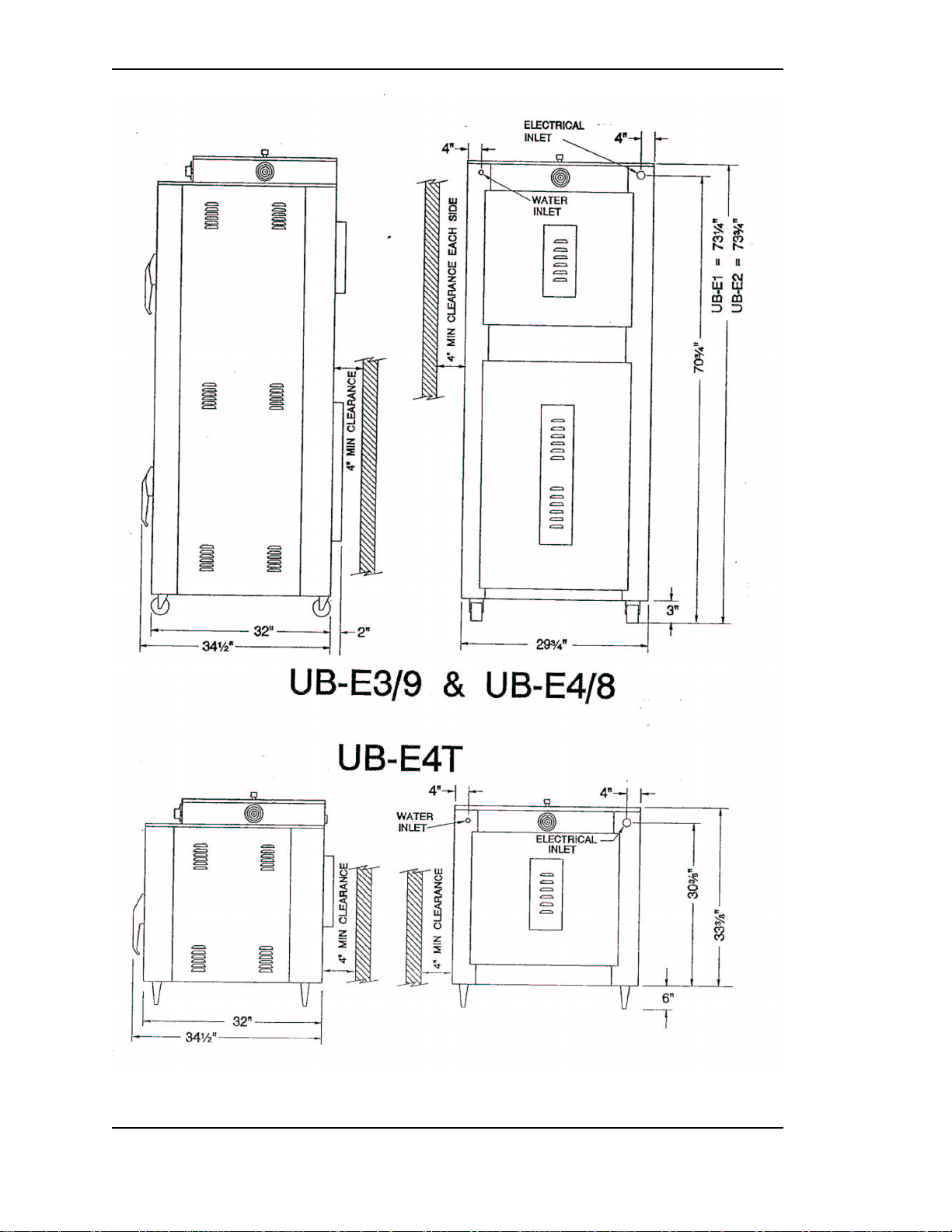
measure 30" wide and 32" deep (34½" with the Door Latch). The UB–E3/9 stands 73¼" high
(including the Casters), while the UB–E4/8 measures 73¾" high. The UB–E4T measures 33½"
high (without the 6" Adjustable Appliance Legs). Each unit takes up less than seven square feet of
floor or counter space!
NU–VU® has done operating cost comparisons with gas-fired convection ovens. This data was
generated in conjunction with input from Pacific Gas and Electric. Based on standard assumptions
as to operating conditions for each unit and costs supplied by Pacific Gas and Electric the NU–
VU® UB–E3/9, UB–E4/8 and UB–E4T Oven sections are directly comparable in operating costs
to gas convection ovens of the same size and capacity. Specific data can be supplied upon request.
The use of a reversible Motor/Blower Wheel as a standard feature on the UB–E3/9, UB–E4/8 and
UB–E4T provides various baking and slow cooking capabilities for all meats, fish, poultry, etc. In
addition the versatility of the UB–E3/9, UB–E4/8 or UB–E4T can be enhanced through the
following options:
• COOK–N–HOLD . . . The COOK–N–HOLD system utilizes dual Oven Temperature
Controls and a 24–Hour Timer to bake or cook your product at one temperature and then
automatically shift to a lower holding temperature.
• INTERNALLY GENERATED STEAM . . . This system injects a water mist into the
baking chamber where it is flashed into steam. This added steam will provide crusty
breads or rolls for product variations.
• AUTO–MIST . . . This Proofer option eliminates the manually-filled Water Pan in the
Proofer by injecting and distributing a fine water mist through-out the proofing chamber
to provide optimum levels of proofing humidity.
NU–VU® FOOD SERVICE SYSTEMS MENOMINEE, MICHIGAN 49858
page 4 SALES FAX (906) 863-5889 • SERVICE FAX (906) 863-6322 (906) 863-4401
Page 7

UB–E3/9, –E4/8 & –E4T OWNER'S MANUAL NU–VU® EQUIPMENT WARRANTY
NU–VU® EQUIPMENT WARRANTY
NU–VU® products are warranted against defects in workmanship and materials. No other express
warranty, written or oral, applies. No person is authorized to give any other warranty or assume
any other liability on behalf of NU–VU®, except by written statement from an officer of NU–
VU®.
Your NU–VU® equipment warranty is limited to the following time periods for the original owner
only:
PARTS LABOR
Inside the United States 12 Months 12 Months
All areas outside the United States 12 Months 12 Months
These time limits will apply in all cases unless prior arrangements have been made and agreed to in
writing.
The NU–VU® EQUIPMENT WARRANTY is composed of the following:
CONSTRUCTION - -
This warranty covers fabricated metal parts such as side walls, element covers, tops, corner posts
(where used), bases, welded frames and other parts for the lifetime of the unit. The unit is made
from welded stainless steel (or aluminum where applicable) and is warranted to retain the integrity
of its construction during its time of use in the original location of installation. NU–VU® reserves
the right to provide the method of, and person to make, any required repairs.
PARTS - -
This limited warranty covers certain electrical, electronic, and mechanical parts for the time
periods described above with the exception of those items detailed under Warranty Limitations.
Customers who maintain an open account may purchase against their account. MasterCard, Visa
and American Express credit cards are also accepted.
The return of defective parts is required. The return of a defective part or component must be made
prior to the issuance of a credit on an open account. If a part that is returned tests satisfactory in
the NU–VU® factory or at an authorized NU–VU® dealer or service agency, NU–VU® may
withhold issuing credit. Replacement parts will be warranted for a period of ninety (90) days
provided they are installed in a manner authorized by NU–VU®.
LABOR - -
We require that you call our NU–VU® Service Department at (906) 863-4401 for service
authorization BEFORE you call any service agency if you wish to claim a labor expense under the
warranty. We may be able to solve your problem over the telephone, or we will schedule a
warranty service call by a reliable service agency in your area.
NU–VU® FOOD SERVICE SYSTEMS MENOMINEE, MICHIGAN 49858
(906) 863-4401 SALES FAX (906) 863-5889 • SERVICE FAX (906) 863-6322 page 5
Page 8

NU–VU® EQUIPMENT WARRANTY UB–E3/9, –E4/8 & –E4T OWNER'S MANUAL
This warranty covers the replacement and installation of parts and components which are included
under PARTS for the appropriate time period indicated on the previous page. This coverage is
limited to the normal mileage allowance for a maximum travel radius of up to fifty (50) miles, and
the normal labor rate times the allowable hours for performing the work as set forth in the
following listing:
NU–VU® FOOD SERVICE SYSTEMS
STANDARD TIME ALLOWANCES FOR WARRANTY REPLACEMENTS
CHANGE PERFORMED CHANGE TIME TEST TIME TOTAL TIME
Oven Motor/Rebalance Fan 1 hr. ½ hr. 1½ hr.
Oven Heating Element 1 hr. ½ hr. 1½ hr.
Control Circuit Board ½ hr. ½ hr. 1 hr.
Control Sensor ½ hr. ½ hr. 1 hr.
Proofer Heating Element ½ hr. ½ hr. 1 hr.
Humidity Element ½ hr. ¼ hr. ¾ hr.
Timer and/or Buzzer ½ hr. 5 min. ½ hr.
Proofer Motor ½ hr. 5 min. ½ hr.
Change/Adjust Micro Switch ½ hr. 5 min. ½ hr.
Contactor/Relay ½ hr. 5 min. ½ hr.
Power Switch ¼ hr. 5 min. ¼ hr.
Indicator Light ¼ hr. 5 min. ¼ hr.
These times are based on servicing a unit that has been installed with allowance made for access
panels on the unit. If the unit is built into a wall that makes servicing very difficult or impossible
without removing part of the counter, wall, trim, etc., the extra time for gaining access shall be
charged to the owner of the unit.
NU–VU® has determined that the listed times, which are based on the period of time necessary for
a trained service person to perform the work noted, are fair and reasonable. If a problem is not
diagnosed within a half hour, the service person must contact the NU–VU® Service Department
via telephone. The Service Department is available for assistance Monday through Friday from
7:00 a.m. to 5:00 p.m. (Central Standard Time). Additional time for problem solving will not be
allowed unless this procedure is followed. An appointment for servicing a unit should be set up
since time will not be allowed for waiting to service a unit. Unless the service person justifies extra
time for performing the work noted, charges for work performed by the service person in excess of
the allowed time shall either be billed to the owner of the equipment or denied.
IMPORTANT: NU–VU® WILL NOT PAY FOR ANY SERVICE CALLS AS
WARRANTY WORK IF A NU–VU® AUTHORIZED SERVICE AGENCY
DETERMINES THAT YOUR UNIT IS SET UP AND OPERATING PROPERLY!
EXTENDED WARRANTY:
Available at an additional charge. Please ask for a quote depending upon the type of warranty
requested.
NU–VU® FOOD SERVICE SYSTEMS MENOMINEE, MICHIGAN 49858
page 6 SALES FAX (906) 863-5889 • SERVICE FAX (906) 863-6322 (906) 863-4401
Page 9

UB–E3/9, –E4/8 & –E4T OWNER'S MANUAL NU–VU® EQUIPMENT WARRANTY
WARRANTY LIMITATIONS:
NU–VU® will pay for parts and labor under warranty if there is a defective component, but not
for:
• Parts damaged in shipment beyond the confines of the NU–VU® factory.
• Normal operational wear and tear on the following parts Light bulbs and fuses
Door handles, catches and gaskets
• Damage attributable to customer abuse, including but not limited to Proofer water pan allowed to run dry and burn
Proofer fan motor damaged from not following outlined Dry-Out Procedure
Lack of regular cleaning and/or maintenance
Leaks resulting from the removal of sealant in the unit
• Power supply problems, including Insufficient or incorrect voltage
Damage to electrical components caused by a power surge or spike
Incorrect installation (i.e., separate neutral and ground not supplied, or incorrect
location of high-voltage power leg for 240-volt 3-phase units)
Damage to electrical components resulting from use of an incorrect power supply
cord or circuit breaker
• Operational problems resulting from customer's failure to follow established procedures
outlined in the Owner's Manual.
• A service call if nothing wrong is found (parts still work per spec when tested).
• Recalibration of temperature and humidity controls (all controls are carefully calibrated
and tested at our facility before shipment).
• Any equipment moved from the place of original installation unless NU–VU® agrees in
writing to continue the warranty after the relocation.
• Ongoing operational adjustments due to changing environmental conditions or normal
wear and tear.
• Any overtime charges. NU–VU® will pay straight time only for any work performed on
NU–VU® equipment.
Food service equipment and parts must be installed and maintained in accordance with NU–VU®
instructions. Users are responsible for the suitability of the units or parts to their application. There
is no warranty against damage resulting from accident, abuse, alteration, misapplication,
inadequate storage prior to installation, or improper specification or other operating conditions
beyond our control. Claims against carrier's damage in transit must be filed by the buyer and,
therefore, the buyer must inspect the product immediately upon receipt.
THIS WARRANTY DOES NOT COVER ADJUSTMENTS
DUE TO NORMAL ON-GOING USE!!!
NU–VU® FOOD SERVICE SYSTEMS MENOMINEE, MICHIGAN 49858
(906) 863-4401 SALES FAX (906) 863-5889 • SERVICE FAX (906) 863-6322 page 7
Page 10

NU–VU® EQUIPMENT WARRANTY UB–E3/9, –E4/8 & –E4T OWNER'S MANUAL
PARTS RETURN PROCEDURES AND CONDITIONS:
The following procedure shall be followed for the return of parts to the factory for credit
consideration:
• All parts received by NU–VU® must have a completed Return Authorization Form as
supplied by NU–VU® with the part. Complete and return this Authorization Form with
the defective part(s).
• Parts MUST be packed securely so that in-transit damage cannot occur.
• Prepay shipment. Any parts returned collect will be refused by our Receiving
Department. Credit will be issued on proper returns only.
• As soon as parts are tested and confirmed as defective, credit will be issued against them.
• If the engineering test shows the component is not defective and in good working
condition, it may be returned to you along with your request for payment.
NU–VU® FOOD SERVICE SYSTEMS MENOMINEE, MICHIGAN 49858
page 8 SALES FAX (906) 863-5889 • SERVICE FAX (906) 863-6322 (906) 863-4401
Page 11

UB–E3/9, –E4/8 & –E4T OWNER'S MANUAL RECEIPT AND INSTALLATION
RECEIPT AND INSTALLATION
RECEIPT:
It is essential to inspect the unit immediately when it arrives. NU–VU® has placed instructions on
the packaging to help avoid damage in transit. However, accidents or negligent handling can
produce hidden damage. These steps should be followed:
A. Inspect the entire perimeter of the package for damage or punctures to the packing
material. This may indicate damage to the unit inside. Call any and all packing damage
to the attention of the delivery person.
B. If any packing damage is found uncrate the unit immediately in the presence of the
delivery person to determine if the unit is damaged. If any damage is found indicate the
type and amount of damage on the shipping documents and notify NU–VU® at (906)
863-4401 immediately after filing a freight claim.
C. Uncrate the unit carefully and check the entire unit (top, sides, front and back) for any
visible or hidden damage.
D. Remove the unit from the shipping pallet and inspect the bottom for any damage.
E. If any damage is noted after the driver leaves immediately contact the freight company
and NU–VU® Food Service Systems.
F. Check the Door(s). Make sure each Door closes completely, and that the Door Gasket
seals firmly (refer to the DOOR TEST PROCEDURE under DOOR LATCH, How to
Adjust in the SERVICE AND REPLACEMENT GUIDE). If it does not close and seal
properly please contact the NU–VU® Service Department for instructions and assistance
in any required adjustments.
INSTALLATION PROCEDURES:
NU–VU® recommends that your UB–E3/9, UB–E4/8 or UB–E4T be installed by a licensed
professional to ensure proper positioning and connections. Failure to install your UB–E3/9, UB–
E4/8 or UB–E4T properly may void your product warranty.
Move the unit into the area where it is to be operated. Attach any optional 6" Appliance Legs to the
bottom of the UB–E4T. The Legs screw into threaded holes in the corners of the base.
Position the unit where it will be operated, allowing adequate clearances around the unit for proper
cooling and operation. NU–VU® recommends a minimum clearance of 4" at the back and on each
side of the Oven. Make sure the unit sits level and solid. Adjust or shim the Casters, Appliance
Legs or Oven base as necessary.
Check to determine that the power source is the same voltage and phase as that indicated on the
label on the side of the unit. If the voltage and/or phase is not the same call NU–VU® for
instructions on changing the voltage and/or phase of the equipment.
IMPORTANT: DO NOT ATTACH UNIT IF THE POWER SOURCE DOES NOT
COINCIDE WITH THE UNIT LABEL!!!
#
NU–VU® FOOD SERVICE SYSTEMS MENOMINEE, MICHIGAN 49858
(906) 863-4401 SALES FAX (906) 863-5889 • SERVICE FAX (906) 863-6322 page 9
Page 12
RECEIPT AND INSTALLATION UB–E3/9, –E4/8 & –E4T OWNER'S MANUAL
#1 Installation
NU–VU® FOOD SERVICE SYSTEMS MENOMINEE, MICHIGAN 49858
page 10 SALES FAX (906) 863-5889 • SERVICE FAX (906) 863-6322 (906) 863-4401
Page 13
UB–E3/9, –E4/8 & –E4T OWNER'S MANUAL RECEIPT AND INSTALLATION
A qualified installer or electrician should remove the Outside Top of the unit to expose the power
terminal connections. A copy of the unit wiring schematic is attached to the inside of the unit near
the power terminal connections.
IMPORTANT: ALL POWER SHOULD BE TURNED OFF AT THE WALL
BREAKER WHILE THE UNIT IS BEING CONNECTED!!!
#2 - Electrical Connections
The UB–E3/9, UB–E4/8 or UB–E4T should be connected according to all national and local
electrical codes, either through a plug-type connection or direct wiring. All connections must be
made with COPPER WIRE ONLY in the correct gauge for the application. Provide enough slack in
the wiring to allow for equipment to be moved about during installation and any future required
servicing.
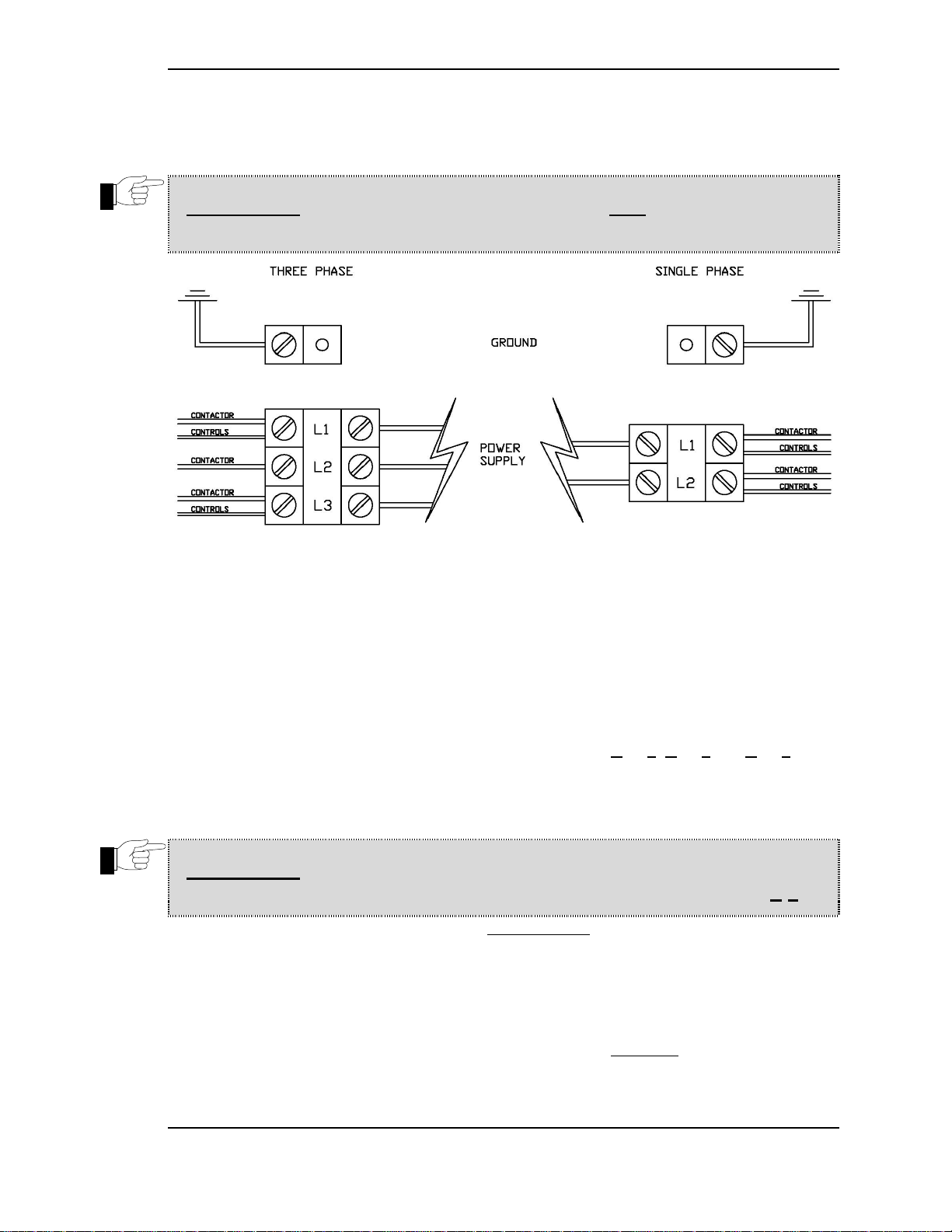
The following steps should be carefully observed (refer to Illusration #2 above):
A. Take note of the labeling on the terminal connections (Line 1, Line 2 and Line 3) at the
Power Terminal Block.
B. Carefully identify the power source connections and attach them to the appropriate
terminals. Make sure all connections are clean and tight.
IMPORTANT: IN ANY 240-VOLT THREE PHASE SYSTEM THE WILD LEG
(240 VOLTS TO NEUTRAL) MUST ALWAYS BE CONNECTED TO L-2!!!
C. Be sure the unit is properly grounded BEFORE USE by attaching a grounding wire to the
Ground Lug next to the Power Terminal Block.
D. Carefully set all Switches and Controls on the unit to the OFF position and engage the
main power supply.
E. Check the voltage at the connections on the Power Terminal Block with a voltmeter to
confirm conformity with the unit label requirements. If all readings are correct the unit is
ready for its INITIAL START–UP. If the readings DO NOT coincide with the unit
requirements you must call the NU–VU® Service Department for instructions.
NU–VU® FOOD SERVICE SYSTEMS MENOMINEE, MICHIGAN 49858
(906) 863-4401 SALES FAX (906) 863-5889 • SERVICE FAX (906) 863-6322 page 11
Page 14

RECEIPT AND INSTALLATION UB–E3/9, –E4/8 & –E4T OWNER'S MANUAL
F. Replace the Outside Top on the unit. Be careful not to pull or pinch any wires while
installing the panel.
G. Complete the installation of the optional water supply to the unit (refer to
INSTALLATION OF WATER SUPPLY immediately following).
H. Push the unit back into place. Make sure the unit is level and solid.
INSTALLATION OF WATER SUPPLY:
IMPORTANT: FAILURE TO FOLLOW THESE INSTRUCTIONS OR
IMPROPER INSTALLATION MAY CAUSE SEVERE EQUIPMENT DAMAGE
OR EVEN PERSONAL INJURY, AND MAY ALSO VOID ALL OR PART OF
YOUR NU–VU® EQUIPMENT WARRANTY!!!
IMPORTANT: NU–VU® strongly recommends that SOFT WATER ONLY be used in any unit
requiring a water supply. Also, a good quality water filter MUST be installed in-line between the
unit connection and the water supply to guard against clogging and mineral build-up in the
components. This is extremely important in areas having hard water. The water filter may be
installed at the water source or adjacent to the Water Inlet Fitting on the rear of the unit, whichever
is more convenient for you.
IMPORTANT: THIS UNIT NEEDS TO BE INSTALLED WITH ADEQUATE
BACKFLOW PROTECTION TO COMPLY WITH APPLICABLE FEDERAL,
STATE AND LOCAL CODES.
IMPORTANT: THIS UNIT REQUIRES A SCREEN OF AT LEAST 100 MESH
TO BE INSTALLED IMMEDIATELY UPSTREAM OF ALL CHECK VALVE
TYPE BACKFLOW PREVENTERS USED FOR WATER SUPPLY
PROTECTION. THE SCREEN SHALL BE ACCESSIBLE AND REMOVABLE
FOR CLEANING OR REPLACEMENT.
Please follow these steps to connect a water supply to your unit:
A. Run ¼" tubing from the water supply line to the unit location. Allow some slack for final
unit positioning and service. Avoid any kinks or strains on the tubing and place the
tubing where it will not be damaged in any way.
B. The tubing end that attaches to the unit must not be damaged or deformed in any way.
The cut end should be cut straight and clean with no deforming of the tubing. All burrs
and sharp edges should be removed to ensure a proper fit and leak-free connection.
C. Position the tubing so that the tubing runs straight into the Water Intake Fitting. Be
careful not to kink the tubing if you bend it, and do not bend the tubing within two (2)
inches of the end.
D. The two-part compression fitting (tapered collar and nut) is placed approximately 1"
onto the tubing so that the collar is inside of the nut and the threaded opening of the nut is
toward the Water Intake Fitting.
NU–VU® FOOD SERVICE SYSTEMS MENOMINEE, MICHIGAN 49858
page 12 SALES FAX (906) 863-5889 • SERVICE FAX (906) 863-6322 (906) 863-4401
Page 15

UB–E3/9, –E4/8 & –E4T OWNER'S MANUAL RECEIPT AND INSTALLATION
E. Push the tubing all the way into the Water Intake Fitting (approximately ¼") and hold it
there while you thread the compression nut onto the Water Intake Fitting. Tighten the
compression nut with an open-end wrench. DO NOT OVER–TIGHTEN!!! If the joint
leaks when tested and further gentle tightening does not stop the leak the two-part
compression fitting must be replaced.
Careful attention to these simple procedures will help to ensure an installation without leaks. If you
have any questions or problems please call the NU–VU® Service Department at (906) 863-4401.
NU–VU® FOOD SERVICE SYSTEMS MENOMINEE, MICHIGAN 49858
(906) 863-4401 SALES FAX (906) 863-5889 • SERVICE FAX (906) 863-6322 page 13
Page 16
INITIAL START–UP UB–E3/9, –E4/8 & –E4T OWNER'S MANUAL
INITIAL START–UP
STANDARD OVEN:
A. Make sure any Sidewall Dampers on the Oven Sidewalls slide freely back and forth.
Leave them in the OPEN position.
B. Unscrew the glass Light Globes in the rear of the Oven. Install the included 40-watt
Appliance Bulbs and replace the Light Globes. Close the Oven Door securely. Make sure
all Controls and Switches are in the OFF position.
C. Engage the main electrical supply.
D. Set the Motor Reversing Switch to LO. Set the Oven Power Switch to ON. The Oven
Blower Wheel should rotate in a clockwise direction when viewed from the open end.
E. Open the Oven Door. The Oven Motor should come to a complete stop. Close the Oven
Door and let the Motor run up to speed.
F. Set the Motor Reversing Switch to the OFF position and let the Motor come to a
complete stop. Set the Motor Reversing Switch to HI. The Blower Wheel should now
rotate in a counter-clockwise direction.
G. Set the Oven Temperature Control to any desired temperature over 300F. The
Temperature Control Indicator Light should light up.
WARNING: NEVER CHANGE THE MOTOR REVERSING SWITCH FROM LO
TO HI, OR FROM HI TO LO, WHILE THE BLOWER WHEEL IS STILL
TURNING!!! DOING SO MAY DAMAGE THE POWER SWITCH, OVEN
MOTOR OR MOTOR REVERSING SWITCH!!!
H. Place a quality oven thermometer in the center of a baking pan in the center of the Oven.
I. Check the reading on the thermometer against the setting on the Temperature Control
when the Temperature Control Indicator Light goes out. If the readings differ by more than
10F the Temperature Control may need a simple adjustment (refer to TEMPERATURE
CONTROL, How to Adjust in the SERVICE AND REPLACEMENT GUIDE). Please call
the NU–VU® Service Department BEFORE attempting adjustment or recalibration of any
Control.
NOTE: Please allow the Temperature Control to cycle two or three times to allow the
Oven temperature to stabilize BEFORE comparing the readings.
J. Set the Oven Timer to 5 minutes and allow it to count down to "0". The Buzzer Alarm
should sound at the end of the timed cycle. If the Buzzer and/or Timer does not work
please call NU-VU®.
K. Return all Controls and Switches to their OFF positions.
WITH COOK–N–HOLD OPTION:
A. Make sure any Sidewall Dampers on the Oven Sidewalls slide freely back and forth.
Leave them in the OPEN position.
B. Unscrew the glass Light Globes in the rear of the Oven. Install the included 40-watt
Appliance Bulbs and replace the Light Globes. Close the Oven Door securely. Make sure
all Controls and Switches are in the OFF position.
C. Engage the main electrical supply.
D. Set the Motor Reversing Switch to LO. Set the Oven Power Switch to ON. The Oven
NU–VU® FOOD SERVICE SYSTEMS MENOMINEE, MICHIGAN 49858
page 14 SALES FAX (906) 863-5889 • SERVICE FAX (906) 863-6322 (906) 863-4401
Page 17

UB–E3/9, –E4/8 & –E4T OWNER'S MANUAL INITIAL START–UP
Blower Wheel should rotate in a clockwise direction when viewed from the open end.
E. Open the Oven Door. The Oven Motor should come to a complete stop. Close the Oven
Door and let the Motor run up to speed.
F. Set the Motor Reversing Switch to the OFF position and let the Motor come to a
complete stop. Set the Motor Reversing Switch to HI. The Blower Wheel should now
rotate in a counter-clockwise direction.
G. Make sure the 24–Hour Timer is set to "0" and then set the Hold Temperature Control to
200. The Hold Temperature Control Indicator Light should light up.
WARNING: NEVER CHANGE THE MOTOR REVERSING SWITCH FROM LO
TO HI, OR FROM HI TO LO, WHILE THE BLOWER WHEEL IS STILL
TURNING!!! DOING SO MAY DAMAGE THE POWER SWITCH, OVEN
MOTOR OR MOTOR REVERSING SWITCH!!!
H. Set the Oven Temperature Control to 300 and then set the 24–Hour Timer to 3 hours or
more. The Oven Temperature Control Indicator Light should light up as soon as the 24–
Hour Timer is moved off of "0", and the Hold Temperature Control Indicator Light
should go out.
I. Place a quality oven thermometer in the center of a baking pan in the center of the Oven.
J. Check the reading on the thermometer against the setting on the Temperature Control
when the Temperature Control Indicator Light goes out. If the readings differ by more
than 10F the Temperature Control may need a simple adjustment (refer to
TEMPERATURE CONTROL, How to Adjust in the SERVICE AND REPLACEMENT
GUIDE). Please call the NU–VU® Service Department BEFORE attempting adjustment
or recalibration of any Control.
NOTE: Please allow the Temperature Control to cycle two or three times to allow the
Oven temperature to stabilize BEFORE comparing the readings.
K. Set the 60–Minute Oven Timer to 5 minutes and allow it to count down to "0". The
Buzzer Alarm should sound at the end of the timed cycle. If the Buzzer and/or Timer
does not work please call NU-VU®.
L. Return all Controls and Switches to their OFF positions.
WITH INTERNAL STEAM OPTION:
A. Make sure any Sidewall Dampers on the Oven Sidewalls slide freely back and forth.
Leave them in the OPEN position.
B. Unscrew the glass Light Globes in the rear of the Oven. Install the included 40-watt
Appliance Bulbs and replace the Light Globes. Close the Oven Door securely. Make sure
all Controls and Switches are in the OFF position.
C. Engage the main electrical and water supplies.
D. Set the Motor Reversing Switch to LO. Set the Oven Power Switch to ON. The Oven
Blower Wheel should rotate in a clockwise direction when viewed from the open end.
E. Open the Oven Door. The Oven Motor should come to a complete stop.
NU–VU® FOOD SERVICE SYSTEMS MENOMINEE, MICHIGAN 49858
(906) 863-4401 SALES FAX (906) 863-5889 • SERVICE FAX (906) 863-6322 page 15
Page 18

INITIAL START–UP UB–E3/9, –E4/8 & –E4T OWNER'S MANUAL
F. Hold in the Door Micro Switch in the Hinge side of the door jamb to activate the Oven
Motor. Press and hold down the Steam Switch. The Steam Water Solenoid Valve should
give an audible "click", allowing a water mist to spray from the Injection Nozzle into the
Blower Wheel. The water spray will stop as soon as you release the Steam Switch.
Release the Micro Switch, close the Oven Door and let the Motor run back up to speed.
G. Set the Motor Reversing Switch to the OFF position and let the Motor come to a
complete stop. Set the Motor Reversing Switch to HI. The Blower Wheel should now
rotate in a counter-clockwise direction.
WARNING: NEVER CHANGE THE MOTOR REVERSING SWITCH FROM LO
TO HI, OR FROM HI TO LO, WHILE THE BLOWER WHEEL IS STILL
TURNING!!! DOING SO MAY DAMAGE THE POWER SWITCH, OVEN
MOTOR OR MOTOR REVERSING SWITCH!!!
H. Set the Oven Temperature Control to any desired temperature over 300F. The
Temperature Control Indicator Light should light up.
I. Place a quality oven thermometer in the center of a baking pan in the center of the Oven.
J. Check the reading on the thermometer against the setting on the Temperature Control
`when the Temperature Control Indicator Light goes out. If the readings differ by more
than 10F the Temperature Control may need a simple adjustment (refer to
TEMPERATURE CONTROL, How to Adjust in the SERVICE AND REPLACEMENT
GUIDE). Please call the NU–VU® Service Department BEFORE attempting adjustment
or recalibration of any Control.
NOTE: Please allow the Temperature Control to cycle two or three times to allow the
Oven temperature to stabilize BEFORE comparing the readings.
K. Set the 60–Minute Oven Timer to 5 minutes and allow it to count down to "0". The
Buzzer Alarm should sound at the end of the timed cycle. If the Buzzer and/or Timer
does not work please call NU-VU®.
L. Return all Controls and Switches to their OFF positions.
STANDARD PROOFER:
A. Unscrew the glass Light Globes in the rear of the Proofer. Install the 40-watt Appliance
Bulbs and replace the glass Light Globes. Close the Proofer Door securely.
B. Set the Proofer Power Switch to ON. The Fan Blade should rotate in a counter-
clockwise direction.
C. Set the Proofer Temperature Control to any selected proofing temperature (generally
95-105). The Temperature Control Indicator Light should light up.
D. Place a reliable oven thermometer in the center of the Proofer.
E. Check the thermometer reading against the Temperature Control setting when the
Temperature Control Indicator Light goes out. If the readings differ by more than 10 the
Temperature Control may need a simple adjustment (refer to TEMPERATURE
CONTROL, How to Adjust in the SERVICE AND REPLACEMENT GUIDE). Please call
the NU–VU® Service Department BEFORE attempting adjustment or recalibration of
any Control.
NOTE: Please allow the Temperature Control to cycle two or three times to allow the
temperature to stabilize BEFORE comparing the readings.
F. Remove the Water Pan. Set the Proofer Humidity Control to #5 or #6. The Humidity
NU–VU® FOOD SERVICE SYSTEMS MENOMINEE, MICHIGAN 49858
page 16 SALES FAX (906) 863-5889 • SERVICE FAX (906) 863-6322 (906) 863-4401
Page 19

UB–E3/9, –E4/8 & –E4T OWNER'S MANUAL INITIAL START–UP
Control Indicator Light should light up and the round Humidity Element in the front of
the Proofer will begin to heat up.
G. Fill the Water Pan with approximately 2" of water and place it on the Humidity Element.
Close the Proofer Door securely. The water should begin to heat up and in a few minutes,
a light fogging will begin to form on the Proofer Door glass.
H. Return all Controls and Switches to their OFF positions.
AUTO–MIST PROOFER:
A. Unscrew the glass Light Globes in the rear of the Proofer. Install the 40-watt Appliance
Bulbs and replace the glass Light Globes. Leave the Proofer Door open.
B. Set the Proofer Power Switch to ON. The Blower Wheel should rotate in a counter-
clockwise direction.
C. Set the Humidity Control to #9 or #10. The Humidity Control Indicator Light should
light up and a light water mist will be sprayed from the Injection Nozzle into the Proofer
Blower Wheel. In a second or two the spray will stop and the Indicator Light will go out.
After a short pause the Humidity Control will cycle again.
NOTE: The AUTO–MIST option controls the humidity in the Proofer by using a solid-
state Repeat Cycle Timer. This Timer has a fixed "OFF" time of 45 seconds and an
"ON" time that is adjustable from a minimum of 0.2 to a maximum of 2.0 seconds.
Changing the setting of the Humidity Control varies the "ON" time, regulating the
duration of the water spray and the resulting humidity level in the Proofer.
D. Close the Proofer Door. Set the Proofer Temperature Control to any selected proofing
temperature (generally 95-105). The Temperature Control Indicator Light should light
up.
E. Place a reliable oven thermometer in the center of the Proofer.
F. Check the thermometer reading against the Temperature Control setting when the
Temperature Control Indicator Light goes out. If the readings differ by more than 10 the
Temperature Control may need a simple adjustment (refer to TEMPERATURE
CONTROL, How to Adjust in the SERVICE AND REPLACEMENT GUIDE). Please call
the NU–VU® Service Department BEFORE attempting adjustment or recalibration of
any Control.
NOTE: Please allow the Temperature Control to cycle two or three times to allow the
temperature to stabilize BEFORE comparing the readings.
NU–VU® FOOD SERVICE SYSTEMS MENOMINEE, MICHIGAN 49858
(906) 863-4401 SALES FAX (906) 863-5889 • SERVICE FAX (906) 863-6322 page 17
Page 20

MAINTENANCE AND CLEANING GUIDE UB–E3/9, –E4/8 & –E4T OWNER'S MANUAL
OPERATING INSTRUCTIONS
PROOFER:
A. Set out the desired product for thawing. Be sure to allow sufficient time in your schedule
for both the product and your equipment to reach the correct conditions.
B. Prepare the Proofer:
1. Turn the Proofer Power Switch ON at least 20 minutes prior to use.
2. Set the Proofer Temperature Control to the required setting.
3. FOR THE STANDARD PROOFER - a. Make sure the Water Pan contains no less than 2" of water. This should be
checked every time you load the Proofer and at least every other hour.
FOR THE AUTO–MIST PROOFER - -
a. Make sure the water supply to the Proofer is not interrupted or shut off. The
Injection Nozzle should spray a fine intermittent water mist into the Blower
Wheel when the Humidity Control Indicator Light lights up.
4. When your product is ready and JUST PRIOR TO LOADING PRODUCT INTO
THE PROOFER set the Humidity Control to the required setting.
IMPORTANT: ALWAYS REDUCE THE HUMIDITY SETTING TO A MINIMAL
LEVEL WHEN RUNNING THE PROOFER WITHOUT PRODUCT INSIDE!!!
5. The Proofer is ready for use when the Temperature and Humidity Control Indicator
Lights go out and a light fogging appears on the glass of the Proofer Door.
C. Load the product. Center the pans front to back as much as possible to allow proper air
circulation over and around your product.
NOTE: The Indicator Lights will come on again as the Temperature and Humidity
Controls regulate the conditions in the Proofer. This is normal and may happen
several times during a proofing cycle.
D. Monitor the proofing process. Your Proofer is functioning properly if there is a slight
fogging on the Door. No fogging means your Proofer may be running too hot, too dry, or
both. Excessive fogging (with water running down the glass) means your Proofer may be
running too cold, too wet, or both. Check the product and adjust the Proofer Temperature
and Humidity Controls as necessary.
TIP: If water accumulates on the floor in front of your Proofer from drippings out of
the Proofer Door you are probably proofing with too much humidity. Decrease the
Humidity Control setting. If water on the floor is a constant problem for you please
call the NU–VU® Service Department at (906) 863-4401 for assistance.
E. Load the Oven when your product is fully proofed. Yeast products should be _ to ¾ of
the desired finished size at the end of the proof cycle. Generally speaking yeast products
should also be slightly tacky to the touch as they are loaded into the Oven.
F. When you are finished using the Proofer for the day the DAILY DRY–OUT
PROCEDURES must be performed (refer to the MAINTENANCE AND CLEANING
GUIDE).
NU–VU® FOOD SERVICE SYSTEMS MENOMINEE, MICHIGAN 49858
page 18 SALES FAX (906) 863-5889 • SERVICE FAX (906) 863-6322 (906) 863-4401
Page 21

UB–E3/9, –E4/8 & –E4T OWNER'S MANUAL MAINTENANCE AND CLEANING GUIDE
IMPORTANT: ALL OF THE PROOFER DRY–OUT PROCEDURES MUST BE
CARRIED OUT ON A DAILY BASIS!!!
STANDARD OVEN:
The UB–E3/9, UB–E4/8 and UB–E4T may be equipped with a Motor Reversing Switch. There are
three (3) positions for this Switch:
OFF Turns the Oven Motor OFF. You must set the Motor Reversing Switch to this
position FIRST and allow the Blower Wheel to come to a complete stop whenever
you switch the Motor/Blower Wheel from LO to HI, or from HI to LO.
HI Motor/Blower Wheel rotation is counter-clockwise, air velocity and delivery volume
are highest.
LO Motor/Blower Wheel rotation is clock-wise, air velocity and delivery volume are
reduced.
WARNING: NEVER CHANGE THE MOTOR REVERSING SWITCH FROM LO
TO HI, OR FROM HI TO LO, WHILE THE BLOWER WHEEL IS STILL
TURNING!!! DOING SO MAY DAMAGE THE POWER SWITCH, OVEN
MOTOR OR MOTOR REVERSING SWITCH!!!
The Blower Wheel is designed to give different air velocities when the rotation direction is
changed. The HI setting will give the highest velocity and volume of heated air while the LO
setting will deliver less air at a lower velocity. Different air speeds may be employed for different
products. Generally speaking the HI setting will be used for dough products such as breads, rolls,
croissants, Danish, etc., while the LO setting may be used for cookies or delicate cakes (it is also
most useful in conjunction with the optional COOK–N–HOLD feature for these NU–VU® units).
Only you can determine the optimum air velocity for your desired end results.
IMPORTANT: THE MOTOR/BLOWER WHEEL MUST ALWAYS BE
RUNNING EXCEPT WHILE THE OVEN DOOR IS OPEN WHEN YOU ARE
LOADING OR UNLOADING YOUR PRODUCT!!!
NOTE: At the beginning of each day you may want to pre-heat your Oven
approximately 25 higher than the required baking temperature. Since your Oven
requires time to reach the proper operating temperature you should plan ahead so your
Oven and product are ready at the same time. When the desired temperature is reached
(approximately 15-20 minutes after start-up) the Oven Temperature Control Indicator
Light will go out. It is not necessary to reset to pre-heat temperature with each load
unless you are baking new items at a much higher temperature.
Follow these general instructions for proper baking results:
A. Determine the product to be baked.
B. Check the recommended temperature for the product to be baked and set your
Temperature Control accordingly.
NU–VU® FOOD SERVICE SYSTEMS MENOMINEE, MICHIGAN 49858
(906) 863-4401 SALES FAX (906) 863-5889 • SERVICE FAX (906) 863-6322 page 19
Page 22

MAINTENANCE AND CLEANING GUIDE UB–E3/9, –E4/8 & –E4T OWNER'S MANUAL
C. Load your Oven from the top shelf down. If the top shelf is too high to be reached easily
an empty pan should be placed on the top shelf. Push the pans all the way to the rear of
the Oven until they rest against the ends of the Pan Slides. Keep the Oven Door
CLOSED unless loading or unloading to maintain Oven temperature and minimize
energy usage.
NOTE: It is helpful to slowly push the Oven Door closed until the Motor starts. Hold it
about 1" from the closed position for 1 or 2 seconds before latching it securely. This
short delay prevents the sudden build-up of internal pressure (as the Oven Motor starts
up) that may suddenly "pop" the Oven Door open.
IMPORTANT: If your product is 3½ inches or more in height every other shelf should be used
(in the UB–E3/9: the top and bottom shelves; in the UB–E4/8: the 2nd and 4th shelves
from the top). When baking on every other shelf the Sidewall Damper on each side of
the shelf above should be adjusted to close off the air holes on that shelf. Failure to do
this will cause the sides of the product to burn.
D. Set the 60–Minute Oven Timer for the estimated baking time less one to two minutes.
This will assure an indication from the Buzzer Alarm prior to the actual end of the
baking time and help prevent over-baking.
E. As soon as the product is finished open the Oven Door and remove the product quickly.
Immediately close the Oven Door to minimize temperature loss.
CAUTION: STAND AWAY FROM THE FRONT OF THE OVEN WHEN
OPENING THE OVEN DOOR AFTER A BAKING CYCLE TO AVOID
EXPOSURE TO ESCAPING HEAT AND STEAM!!!
F. You may bake several different items at the same time and temperature, but each
individual pan should have the same type of product on it and be panned in the same
manner.
G. Since your Oven may easily out-bake your Proofer several alternatives should be
considered:
1. Alternate non-proofed products with proofed products in the baking cycle (e.g.-
cookies, puff pastry, muffins, brownies, pies, etc.).
2. Provide additional proofing capacity with a separate NU–VU® Proofer.
3. Schedule baking over a longer period of time.
H. Whenever the baking is completed for the day, or for an extended period, the Oven
Temperature Control should be turned to the OFF position and the Oven Power Switch
set to OFF (see the DAILY DRY–OUT PROCEDURE in the MAINTENANCE AND
CLEANING GUIDE).
IMPORTANT: THE OVEN AND PROOFER DRY–OUT PROCEDURES MUST
BE CARRIED OUT ON A DAILY BASIS!!!
NU–VU® FOOD SERVICE SYSTEMS MENOMINEE, MICHIGAN 49858
page 20 SALES FAX (906) 863-5889 • SERVICE FAX (906) 863-6322 (906) 863-4401
Page 23

UB–E3/9, –E4/8 & –E4T OWNER'S MANUAL MAINTENANCE AND CLEANING GUIDE
COOK–N–HOLD Option - -
The COOK–N–HOLD option allows you to cook a product at one temperature and to hold that
product at a lower temperature.
There are two separate Temperature Controls and a 24-Hour Timer that must be set in order for
you to utilize the COOK–N–HOLD option features of your NU–VU® Oven. The Oven
Temperature Control must be set at the desired initial cooking temperature. The Hold Temperature
Control must be set at the temperature you wish the product to remain at.
IMPORTANT: YOUR NU–VU® OVEN IS WELL INSULATED AND WILL MAINTAIN
THE ORIGINAL COOK TEMPERATURE FOR ½ TO 1 HOUR DEPENDING ON THE
PRODUCT, PRODUCT DENSITY AND LOAD SIZE. THE TEMPERATURE WILL
NOT INSTANTLY DROP TO THE HOLD SETTING AT THE END OF THE TIMED
COOK CYCLE. PLAN YOUR COOK TEMPERATURE, COOK TIME AND HOLD
TEMPERATURE ACCORDINGLY!
Please follow these general guidelines for preparing meats, fish or fowl:
A. Set the Motor Reversing Switch to LO. Set the Oven Power Switch to ON.
B. Set the Cook Temperature Control to the desired cook temperature.
C. Set the 24–Hour Timer for the length of time you want your product to cook.
D. Set the Hold Temperature Control to the desired holding temperature.
E. At the expiration of the cooking time the Hold Temperature Control will automatically
take over and maintain your product at the set hold temperature. Remember, the internal
Oven temperature will not drop immediately to the hold temperature, but will slowly
decrease over a period of time until it matches the set hold temperature.
F. The product will be maintained at the set hold temperature until you remove it from the
Oven, change the setting on the Hold Temperature Control or turn the Oven OFF.
NOTE: If you desire to pre-heat your Oven before loading any product the 24–Hour
Timer must be set for enough time to pre-heat your unit to the desired temperature.
Load the product when the Oven is pre-heated and then reset the 24–Hour Timer to the
correct cook time.
INTERNAL STEAM Option - -
This option uses a manually-operated Steam Switch to activate the Water Solenoid Valve and
spray a fine water mist through the Water Injection Nozzle into the heated Oven chamber. This
water mist flashes into steam and is circulated through-out the Oven cavity by the Blower Wheel.
To operate the INTERNAL STEAM Option:
A. Increase the setting on the Oven Temperature Control just enough so that the
Temperature Control Indicator Light comes on.
B. Press and hold down the spring-loaded Steam Switch to activate the injection system.
The Solenoid Water Valve will open allowing water to spray through the Injector Nozzle
and into the Oven chamber where it flashes into steam. The air in the Oven is saturated
when small water droplets appear on the Oven floor. Release the Steam Switch to stop
the water spray at any time.
C. Reset the Oven Temperature Control to the original temperature if necessary.
D. More steam injections can be used later in the baking cycle for breads and rolls as long
as the Temperature Control Indicator Light is illuminated.
NU–VU® FOOD SERVICE SYSTEMS MENOMINEE, MICHIGAN 49858
(906) 863-4401 SALES FAX (906) 863-5889 • SERVICE FAX (906) 863-6322 page 21
Page 24

MAINTENANCE AND CLEANING GUIDE UB–E3/9, –E4/8 & –E4T OWNER'S MANUAL
MAINTENANCE AND CLEANING GUIDE
MAINTENANCE:
NU–VU® equipment is designed to last for years of useful service. Careful consideration is given
in selecting components for durability, performance and ease of maintenance. For example, both
the Oven Motor and Proofer Motor have sealed bearings and never need to be lubricated. While
NU–VU® equipment is designed for minimum care and maintenance certain steps are required by
the user for maximum life and effectiveness:
• Proper installation of the equipment.
• Correct application and usage of the equipment.
• Dry–Out Procedures performed daily.
• Thorough cleaning on a regular basis.
STANDARD PROOFER DRY–OUT PROCEDURE:
A. Remove the Water Pan. Empty and clean the Water Pan and set it aside.
B. WIPE UP ANY STANDING WATER IN THE BOTTOM OF THE PROOFER!
C. Turn the Proofer Power Switch ON. Leave the Temperature Control and Humidity
Control at their normal settings.
D. Leave the Proofer Door open about 1" to 2" and allow the Proofer to run for about 30
minutes.
E. Turn the Proofer Power Switch OFF. Leave the Proofer Door open by about 1" to 2"
while the Proofer is not in use.
AUTO–MIST PROOFER DRY–OUT PROCEDURE:
A. WIPE UP ANY STANDING WATER IN THE PROOFER! You may need to remove
the Element Cover to do this.
B. Turn the Proofer Power Switch ON. Leave the Temperature Control at its normal setting
but turn the Humidity Control to OFF.
NOTE: Depending on your system you may also need to turn off the water supply.
C. Leave the Proofer Door open about 1" to 2" and allow the Proofer to run for about 30
minutes.
D. Turn the Proofer Power Switch OFF. Leave the Proofer Door open by about 1" to 2"
while the Proofer is not in use.
OVEN DRY–OUT PROCEDURE:
A. Set the Oven Temperature Control and Oven Power Switch to OFF.
B. Leave the Oven Door open about 1" to 2". The residual baking heat will dry out any
moisture that may be trapped in the insulation or other components of the Oven.
C. Leave the Oven Door open by about 1" to 2" while the Oven is not in use.
IMPORTANT: THESE DRY–OUT PROCEDURES MUST BE CARRIED OUT
DAILY TO MAINTAIN YOUR EQUIPMENT IN TOP CONDITION!!! THE
REMOVAL OF ALL RESIDUAL MOISTURE IN THE UNIT CAN EXTEND THE
USEFUL LIFETIME OF YOUR NU–VU® EQUIPMENT!!!
NU–VU® FOOD SERVICE SYSTEMS MENOMINEE, MICHIGAN 49858
page 22 SALES FAX (906) 863-5889 • SERVICE FAX (906) 863-6322 (906) 863-4401
Page 25

UB–E3/9, –E4/8 & –E4T OWNER'S MANUAL MAINTENANCE AND CLEANING GUIDE
CLEANING:
Your NU–VU® UB–E3/9 or UB–E4/8 Oven/Proofer or the UB–E4T Oven should be cleaned
daily or as soon as possible after a spill has occurred. It is essential to maintain a clean unit,
especially if the public views the unit in your place of business. The following general guidelines
should be used for cleaning:
PROOFER - -
• The Proofer Door glass may be cleaned with any good glass-cleaning formula. Be sure to
wipe down the Door Frame, and to clean behind the Door Gasket on the inside of the
Proofer Door. The Door can be removed for cleaning heavy soiling by opening the Door
until it is perpendicular to the face of the unit and then lifting the Door straight up off of
the Hinge pins. Dried-on debris or heavy soiling can be removed with hot soapy water
followed by a rinse with clean fresh water. Wipe the Door dry before replacing it on the
front of the Proofer.
CAUTION: DO NOT USE ABRASIVE CLEANERS ON THE DOOR OR YOU
MAY SCRATCH THE GLASS!!!
• Remove the Proofer Element Cover. Wipe up any standing water in the bottom of the
Proofer and sweep up any solid particles of debris, being careful to keep them away from
the Drain in the floor of the Proofer.
• The Proofer interior (including the Door Jamb) and the Element Cover should be cleaned
on a regular basis (at least once a week) with mild soap and hot water followed by a
thorough rinse with clean fresh water and a sanitizing agent; wiping the interior dry will
help to prevent water spotting. Water spotting and other mineral deposits should be
removed with any mild mineral removal agent as soon as they are noticeable.
• The Proofer Drain can be cleaned with a small tubular or round brush and hot soapy
water, followed by a mild sanitizing agent. If you have drain plumbing attached to the
Proofer Drain you can flush the drain line with hot soapy water, followed by a sanitizer.
If you do not have any drain plumbing attached, remember to empty and clean the Drain
Pan in the support bracket under the Proofer. Replace the Drain Pan before using the
Proofer again.
• Replace the Proofer Element Cover. Leave the Proofer Door open by about 1" to 2"
while the Proofer is not in use.
OVEN - -
• The Oven Door glass may be cleaned with any good glass-cleaning formula. Be sure to
wipe down the Door Frame, and to clean behind the Door Gasket on the inside of the
Oven Door. The Door can be removed for cleaning heavy soiling by opening the Door
until it is perpendicular to the face of the unit and then lifting the Door straight up off of
the Hinge pins. Dried-on debris or heavy soiling can be removed with hot soapy water
followed by a rinse with clean fresh water. Wipe the Door dry before replacing it on the
front of the Oven.
CAUTION: DO NOT USE ABRASIVE CLEANERS ON THE DOOR OR YOU
MAY SCRATCH THE GLASS!!!
NU–VU® FOOD SERVICE SYSTEMS MENOMINEE, MICHIGAN 49858
(906) 863-4401 SALES FAX (906) 863-5889 • SERVICE FAX (906) 863-6322 page 23
Page 26

MAINTENANCE AND CLEANING GUIDE UB–E3/9, –E4/8 & –E4T OWNER'S MANUAL
• The Oven interior (including the Door Jamb) should be wiped out daily
EXTERIOR - -
• All exterior glass may be cleaned with any good glass-cleaning formula.
• The exterior metal surfaces can be cleaned with any good stainless steel cleaner or
polish, or with hot water and a mild soap followed by a thorough rinse with clean fresh
water if it is very soiled.
CAUTION: DO NOT ALLOW WATER NEAR THE CONTROL SURFACES!!!
NOTE:
NU–VU® has had very good results with a product called JIFFY CLEANER. For standard
cleaning simply spray JIFFY on and wipe off. Heavily soiled areas may require a short period of
soaking. This cleaner is available through NU–VU® (Part #51-0002) or through your local
Rochester/Midland distributor or representative.
* * * CAUTION * * *
NU–VU® DOES NOT RECOMMEND the use of any strong commercial or caustic product on
this equipment. DO NOT allow any type of caustic cleaner to come into contact with any
aluminum parts (such as Door Frames), the silicon rubber Door Gaskets, or any of the sealant in
the Oven and Proofer seams and joints. These compounds may cause discoloration and degradation
of these parts resulting in permanent damage. DO NOT use bleach or bleach compounds on any
chromed parts; bleach may damage chrome plating.
NU–VU® FOOD SERVICE SYSTEMS MENOMINEE, MICHIGAN 49858
page 24 SALES FAX (906) 863-5889 • SERVICE FAX (906) 863-6322 (906) 863-4401
Page 27

UB–E3/9, –E4/8 & –E4T OWNER'S MANUAL SERVICE AND REPLACEMENT GUIDE
SERVICE AND REPLACEMENT GUIDE
Your UB–E3/9, UB–E4/8 or UB–E4T has been designed to be serviced quickly and easily. In fact,
any individual who has average mechanical ability can do the work. Our Service Department is
also available to you Monday through Friday from 7:00 a.m. to 5:30 p.m. (Central Standard Time)
should you find yourself with a situation or problem other than what is outlined here. Call NU–
VU® at (906) 863-4401 and ask for the Service Department to order replacement parts, ask
questions, or offer comments.
This SERVICE AND REPLACEMENT GUIDE has been prepared to cover most normal service
problems. If this "trouble-shooting" information does not provide a solution for your particular
problem we ask that you call us for direct assistance. Calling our Service Department before
calling in a repair technician can usually save you both time and unnecessary expense. We want to
do everything we can to minimize your "down-time".
You may need to remove an Access Panel for servicing. DO NOT allow any Access Panels to
drop. When work on the component is finished replace the Panel with care, making sure that all
wires are properly placed and not pulled or pinched. If more than one component is being worked
on try to remove only one component at a time.
IMPORTANT: IMPROPER REPLACEMENT OR INSTALLATION MAY
CAUSE SEVERE EQUIPMENT DAMAGE OR PERSONAL INJURY, AND
MAY ALSO
VOID ALL OR PART OF YOUR NU–VU® EQUIPMENT WARRANTY!!!
TEMPERATURE CONTROL, How To Adjust:
PLEASE CALL THE NU–VU® SERVICE DEPARTMENT AT (906) 863-4401
BEFORE ATTEMPTING TO ADJUST ANY TEMPERATURE CONTROL!
A. Place a reliable thermometer (or the thermocouple of a test instrument) on a pan in the
center of the Oven or Proofer. Turn the unit ON and set the Temperature Control [23 or
32] to its normal setting. Allow the equipment to reach a stable operating temperature.
B. Compare the Temperature Control setting to the reading on the test instrument. If there is
a difference of 25 or more in the Oven or 15 or more in the Proofer you will most likely
need to recalibrate the Temperature Control.
IMPORTANT: Please call the NU–VU® Service Department at (906) 863-4401 for the
correct procedures to recalibrate your equipment!!!
C. If the difference is less than 25 in the Oven or 15 in the Proofer a simple adjustment
may solve the problem:
1. Remove the Knob of the Temperature Control by pulling it straight out from the
face of the unit.
2. Hold the black Knob securely with the back of the clear plastic dial toward you. Use
a phillips screwdriver to loosen the two screws from ¾ to 1 full turn, but do not
remove them!
NU–VU® FOOD SERVICE SYSTEMS MENOMINEE, MICHIGAN 49858
(906) 863-4401 SALES FAX (906) 863-5889 • SERVICE FAX (906) 863-6322 page 25
Page 28

SERVICE AND REPLACEMENT GUIDE UB–E3/9, –E4/8 & –E4T OWNER'S MANUAL
3. To increase the temperature inside the Oven or Proofer carefully rotate the index
line on the clear dial clockwise. Each "click" of adjustment is equal to
approximately 5 of temperature change in the Oven and 2 of temperature change
in the Proofer. To decrease the inside temperature rotate the clear dial counterclockwise.
4. Gently tighten the dial screws and install the Knob. Check the Control setting
against the test instrument and repeat this procedure if necessary.
D. If this procedure fails to bring the temperature reading within the desired specs try
replacing the Temperature Control Sensor. If the temperature is still too far off replace
the Temperature Control Circuit Board.
STANDARD DOOR LATCH, How To Adjust:
Determine if the Oven Door [41] or Proofer Door [42] is fitting too loose (it will leak steam
and hot air past the Gasket) or too tight (it will not close properly, or will "pop" open
unexpectedly). If it is too loose the Door Latch [44] must be adjusted OUT (away from the
unit); if it is too tight the Door Latch must be adjusted IN (towards the unit). Please proceed
as follows:
A. Loosen the two acorn nuts inside the Latch Cover [45] with a small box wrench. Pull the
Latch Cover straight out from the Door to remove it and then remove the acorn nuts.
B. Open the Door and take careful notice of the adjustment plate position against the body
of the Door Latch.
C. Hold the adjustment plate against the body of the Door Latch with one hand while you
loosen the mounting screws with the other hand. Back the screws out approximately three
full turns.
D. CAREFULLY move the Door Latch body IN or OUT under the adjustment plate one
notch at a time. Make sure the Door Latch stays straight up and down and tighten the
mounting screws. Test the Door for proper closing and sealing (refer to the DOOR TEST
PROCEDURE outlined on page 61).
E. Repeat steps "C" and "D" if you are not satisfied with the Door adjustment. If the Door
tests as satisfactory make sure the mounting screws are tightened securely.
F. Install the acorn nuts on the ends of the top and bottom Door Latch screws. Turn the nuts
on all the way until they just contact the back side of the latch bracket, then loosen them
by 1½ to 2 full turns. Install the Latch Cover and tighten the acorn nuts lightly to hold
the Latch Cover in place.
STEAM OPTION DOOR LATCH, How To Adjust:
Determine if the Oven Door or Proofer Door is fitting too loose (it will leak steam and/or hot
air past the Door Gasket) or too tight (it will not close properly, or will "pop" open
unexpectedly). If it is too loose the Strike Hook on the Catch Plate must be adjusted IN
(towards the unit). If it is too tight the Strike Hook must be adjusted OUT (away from the
unit). Please proceed as follows:
A. Open the Door and take careful notice of the Strike Hook position on the top of the Door
Latch Catch Plate (refer to Illustration #26 above).
B. Hold the Strike Hook in position while you loosen the retaining screw with a phillips
screwdriver. Back the screw out approximately 1½ to 2 turns.
NU–VU® FOOD SERVICE SYSTEMS MENOMINEE, MICHIGAN 49858
page 26 SALES FAX (906) 863-5889 • SERVICE FAX (906) 863-6322 (906) 863-4401
Page 29
UB–E3/9, –E4/8 & –E4T OWNER'S MANUAL SERVICE AND REPLACEMENT GUIDE
C. CAREFULLY move the Strike Hook IN or OUT on top of the Catch Plate body one
notch at a time and tighten the retaining screw. Test the Door for proper closing and
sealing (refer to the DOOR TEST PROCEDURE). Proper Catch Plate and Latch
adjustment will leave the Latch Hook fully engaged over the top of the Strike Hook, with
approximately 1/16" of space between the top of the Strike Hook base and the end of the
Latch Hook. Raise or lower the Catch Plate body if necessary.
D. Repeat steps "C" and "D" if you are not satisfied with the Door adjustment. If the Door
tests as satisfactory make sure all mounting and retaining screws are tightened securely.
NOTE: If you have adjusted the Strike Hook IN as far as it will go and the Door is still
loose, your Door Gasket [46] has probably been compressed and has lost its resiliency
and should be replaced.
DOOR TEST PROCEDURE:
A. Cut one or two strips of paper approximately 1" wide and 8" to 10" long.
B. Open the Door slightly, insert a strip of paper between the Gasket and Jamb and close
the Door.
C. Slowly pull the paper strip out. You should feel some resistance as you pull the strip
from between the Gasket and Jamb of a properly adjusted Door. Test the fit at regular 2"
to 3" intervals around the entire Door.
D. If you feel NO resistance at a particular spot the Door is too loose, you have found a
weak or damaged spot in the Door Gasket or the Jamb has been bent in.
E. If you feel HEAVY resistance at a particular spot the Door is too tight or the Jamb has
been bent out.
HINGES, How To Adjust:
Hinges on flush-mount Doors are preset at the factory and should not need adjustment.
However, if you experience any problems with Door operation please call the NU–VU®
Service Department for assistance at (906) 863-4401.
DOOR GASKET, How to Replace:
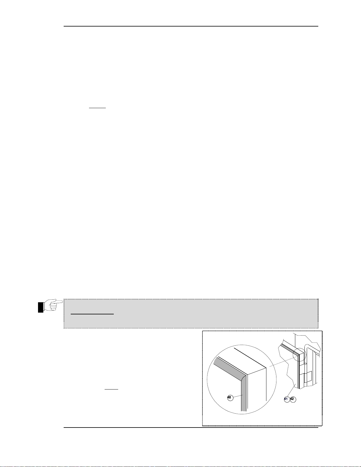
Follow these instructions to correctly install your Door Gasket [46] with minimal problems.
Use the installation kit provided. If you have any problems or questions call NU–VU® at
(906) 863-4401 and ask for the Service Department.
IMPORTANT: DO NOT DISASSEMBLE THE ACTUAL DOOR FRAME WHEN
REPLACING OR REPAIRING THE DOOR GASKET!!!
A. Remove all pieces of the old Gasket.
Thoroughly clean the Door frame in the
area of the new installation. Remove the
old sealant and any baked-on deposits.
B. Pre-cut the replacement Gasket to a size
slightly longer than you require.
C. Put a small amount of soap water into and
around the slot that the new Gasket will fit
into (a small trigger spray bottle works
well). This step is optional but will help in
#3 - Door Gasket
NU–VU® FOOD SERVICE SYSTEMS MENOMINEE, MICHIGAN 49858
(906) 863-4401 SALES FAX (906) 863-5889 • SERVICE FAX (906) 863-6322 page 27
Page 30

SERVICE AND REPLACEMENT GUIDE UB–E3/9, –E4/8 & –E4T OWNER'S MANUAL
the installation.
D. Position the new Gasket over the slot, allowing the ends to extend past the end of the slot.
Press the mounting flange down into the slot on the Door frame. Use a roller tool to force
the mounting flange into the slot by working the tool back and forth along the Gasket.
Make sure the Gasket mounting flange is completely fitted into the slot and that the
Gasket is free to slide back and forth in the slot.
IMPORTANT: DO NOT STRETCH OR PULL ON THE GASKET DURING
THE INSTALLATION PROCESS. THIS WILL LATER CAUSE THE TRIMMED
CORNERS TO SEPARATE AND PULL APART!!!
E. Use a sharp knife or a single-edged razor blade to cut the ends of the Gasket at a 45
angle (you can use the mitered corner joint on the Door as an angle guide). Cut the
Gasket about ¼" longer than the required length and work the excess back into the slot.
This extra Gasket will help to create a nice tight corner joint, and allows for any followup trimming that may be necessary.
F. Work your way around the entire Door (or the section of the Door having the Gasket
replaced). Make sure the Gasket is just tight into the corners. A bulging joint or pucker
along the Gasket indicates a Gasket section that is cut too long. Joints that pull apart
indicate a Gasket section (or sections) that is cut too short.
IMPORTANT: MAKE SURE THAT THE GASKET AND DOOR FRAME ARE
COMPLETELY CLEAN AND DRY BEFORE APPLYING ANY SEALANT!!!
G. Seal the corner joints after the entire Gasket is properly fitted. Pull the joints apart only
enough to put sealant on all the cut edges only. Allow the Gasket joint to come together.
Smooth out any excess sealant to form a smooth surface on the face of the Gasket. Add
more sealant to any spots as necessary and smooth them down.
H. A quality sealant will be dry to the touch and tack-free in one to two hours after
application. However, it will not be completely cured until six to eight hours later. We
recommend that you wait until after your sealant is completely cured before using your
Oven.
WARNING: SOME SEALANTS GIVE OFF ACIDIC FUMES AS THEY CURE.
THESE FUMES MAY CAUSE IRRITATION TO THE EYES AND/OR NASAL
PASSAGES. USE CAUTION WHEN OPENING YOUR UNIT AFTER WAITING
FOR ANY FRESH SEALANT TO SET UP AND CURE!!!
NU–VU® FOOD SERVICE SYSTEMS MENOMINEE, MICHIGAN 49858
page 28 SALES FAX (906) 863-5889 • SERVICE FAX (906) 863-6322 (906) 863-4401
Page 31

UB–E3/9, –E4/8 & –E4T OWNER'S MANUAL REPLACEMENT PARTS LIST
REPLACEMENT PARTS LIST
(UB–E3/9, UB–E4/8 & UB–E4T)
Reference # Description Replacement Part #
ELECTRICAL COMPONENTS:
1 Power Terminal Block ....................................................................................... 50-1332
2 Ground Lug ........................................................................................................ 50-1329
3 Contactor (120v).................................................................................................. 66-2013
Contactor (240v).................................................................................................. 66-2017
4 Oven Temperature Control Circuit Board (425 deg) ........................................ 252-5008
EVO’S (550 deg) ...................................................................................... 252-5001
5 Oven Temperature Control Sensor ................................................................... 252-3001
6 Oven Heating Element, UB–E3/9:
208v, 2000w ..................................................................................... 60-0005-5-A
240v, 2000w ......................................................................................... 60-0004-5
Oven Heating Element, UB–E4/8 and UB–E4T:
208v, 3000w ..................................................................................... 60-0161-1-A
240v, 3000w ..................................................................................... 60-0162-1-A
7 Oven Motor (120v 2 speed rotary switch) ........................................................ 250-1029
(120v single speed) ................................................................................... 250-1027
(240v 2 speed rotarty switch) .................................................................... 250-1060
(240v 2 speed rocker switch or single speed) ............................................ 250-1063
8 Door Switch ...................................................................................................... 252-2004
9 Proofer Temperature Control Circuit Board ..................................................... 252-4001
10 Proofer Temperature Control Sensor .............................................................. 50-0883-B
11 Proofer Humidity Control Circuit Board ........................................................... 252-4001
12 Proofer Humidity Control Sensor ................................................................... 50-0883-B
13 Proofer Heating Element, 120v, 600w ........................................................ 60-0001-1-B
14 Proofer Humidity Element Assembly, 120v, 625w ........................................... 251-2001
Proofer Humidity Element Assembly, 240v, 650W .......................................... 251-2002
15 Proofer Motor (manual fill) (120v) ................................................................... 250-2004
Proofer Motor (manual fill) (240v) ................................................................... 250-2012
16 Cooling Fan Assembly (120v) ............................................................................ 250-3001
Cooling Fan (240v) ................................................................................................. 97525
17 Thermal Overload Safety (425 deg) ................................................................... 252-1021
EVO’S (550 deg) ........................................................................................ 66-1047
18 Buzzer Alarm (replaces 120v rectangular) ....................................................................... 252-1024
Buzzer Alarm (240v rectangular)............................................................................... 66-9003-1-A
(240v or 120v round) ............................................................................................ 252-1022
19 Light Fixture:
Assembly Oven (240V) ........................................................................................ 252-7005
Assembly Proofer (240v) ...................................................................................... 252-7007
Assembly Oven (120V) ......................................................................................... 252-7004
Assembly Proofer (120V) ..................................................................................... 252-7006
NU–VU® FOOD SERVICE SYSTEMS MENOMINEE, MICHIGAN 49858
(906) 863-4401 SALES FAX (906) 863-5889 • SERVICE FAX (906) 863-6322 page 29
Page 32

REPLACEMENT PARTS LIST UB–E3/9, –E4/8 & –E4T OWNER'S MANUAL
OVEN CONTROL COMPONENTS:
21 Oven Power Switch (240v) ................................................................................. 66-3008
Black Breaker Switch (120v) ................................................................... 252-6001
22 Motor Reversing Switch .................................................................................. 50-0280-1
23 Oven Temperature Control (425 deg) ............................................................... 252-5008
EVO’S (550 deg) ..................................................................................... 252-5001
Control Knob .......................................................................................... 253-2003
24 Temperature Control Indicator Light (120v) ................................................... 50-0029-A
Temperature Control Indicator Light (240v) ....................................................... 50-0030
25 Timer
60-Minute Mechanical (120V, 60Hz) ....................................................... 252-1004
60-Minute Mechanical (220V, 60Hz) ....................................................... 252-1019
60-Minute Mechanical (230V, 50Hz) ....................................................... 252-1020
Timer Knob ....................................................................................... 253-2002
PROOFER CONTROL COMPONENTS:
31 Proofer Power Switch(240v) .............................................................................. 66-3008
Black Breaker Switch (120v) ................................................................... 252-6001
32 Proofer Temperature Control ........................................................................... 252-4001
Control Knob .......................................................................................... 253-2003
33 Temperature Control Indicator Light (120v) ................................................... 50-0029-A
Temperature Control Indicator Light (240v) ....................................................... 50-0030
34 Humidity Control (manual fill) ........................................................................... 252-4001
Control Knob (manual fill) ....................................................................... 253-2003
35 Humidity Control Indicator Light (120v) ........................................................ 50-0029-A
Humidity Control Indicator Light (240v) ............................................................ 50-0030
DOOR COMPONENTS:
41 Oven Door, UB–E3/9:
Hinged Left ............................................................................................. 151-1948
Hinged Right .......................................................................................... 151-1949
Oven Door, UB–E4/8 and UB–E4T:
Hinged Left ............................................................................................. 151-1900
Hinged Right .......................................................................................... 151-1920
42 Proofer Door:
UB–E3/9 ................................................................................................ 151-1947
UB–E4/8 ................................................................................................ 153-9841
43 Hinge:
Left–Hinge Door .................................................................................... 254-3011
Right–Hinge Door .................................................................................. 254-3012
44 Handle Assembly .............................................................................................. 254-2007
46 Door Gasket ..................................................................................................... 254-1001
NU–VU® FOOD SERVICE SYSTEMS MENOMINEE, MICHIGAN 49858
page 30 SALES FAX (906) 863-5889 • SERVICE FAX (906) 863-6322 (906) 863-4401
Page 33

UB–E3/9, –E4/8 & –E4T OWNER'S MANUAL REPLACEMENT PARTS LIST
PROOFER INTERIOR COMPONENTS:
64 Water Pan(10 x 12) ............................................................................................. 50-0072
GENERAL EXTERIOR COMPONENTS:
77 Proofer Drain Pan(10 x 6) ................................................................................... 50-0547
COOK–N–HOLD OPTION COMPONENTS:
81 Hold Temperature Control ................................................................................ 252-4001
Control Knob .......................................................................................... 253-2003
82 Hold Temperature Control Indicator Light (120v) ...........................................50-0029-A
Hold Temperature Control Indicator Light (240v) .............................................. 50-0030
83 Hold Temperature Control Circuit Board ......................................................... 252-4001
84 Hold Temperature Control Sensor .................................................................. 50-0883-B
85 Timer, 24–Hour (60HZ) .................................................................................... 252-1005
Timer, 24–Hour (50HZ) ...................................................................................... 66-2016
Timer Knob ............................................................................................. 253-2002
86 Electrical Relay Switch, 20 amp DPDT(120v) .................................................... 50-0433
(240v) ......................................................................................................... 66-9025
87 Transformer .......................................................................................................... 56-0108
INTERNAL STEAM OPTION COMPONENTS:
91 Steam Switch ...................................................................................................... 50-1356
92 Steam Switch Control Indicator Light (120v) ...................................................50-0029-A
Steam Switch Control Indicator Light (240v) ...................................................... 50-0030
93 Water Supply Solenoid Valve (120v)................................................................... 50-0308
Water Supply Solenoid Valve (240v)................................................................... 50-0307
94 Water Injection Nozzle ....................................................................................... 31-0033
95 Steam Injection Timer (120v) ............................................................................... 50-0617
Steam Injection Timer (240v) ............................................................................... 50-0691
AUTO–MIST OPTION COMPONENTS:
101 Humidity Control .............................................................................................. 252-3003
Control Knob .......................................................................................... 253-2003
102 Repeat–Cycle Timer(120v) ................................................................................. 66-8012
(240v) ......................................................................................................... 66-8065
103 Water Supply Solenoid Valve (120v)................................................................... 50-0308
Water Supply Solenoid Valve (240v)................................................................... 50-0307
104 Humidity Injection Nozzle .................................................................................. 31-0033
105 Proofer Motor Assembly(120v) ........................................................................ 250-2010
(240v) ....................................................................................................... 250-2015
NU–VU® FOOD SERVICE SYSTEMS MENOMINEE, MICHIGAN 49858
(906) 863-4401 SALES FAX (906) 863-5889 • SERVICE FAX (906) 863-6322 page 31
Page 34
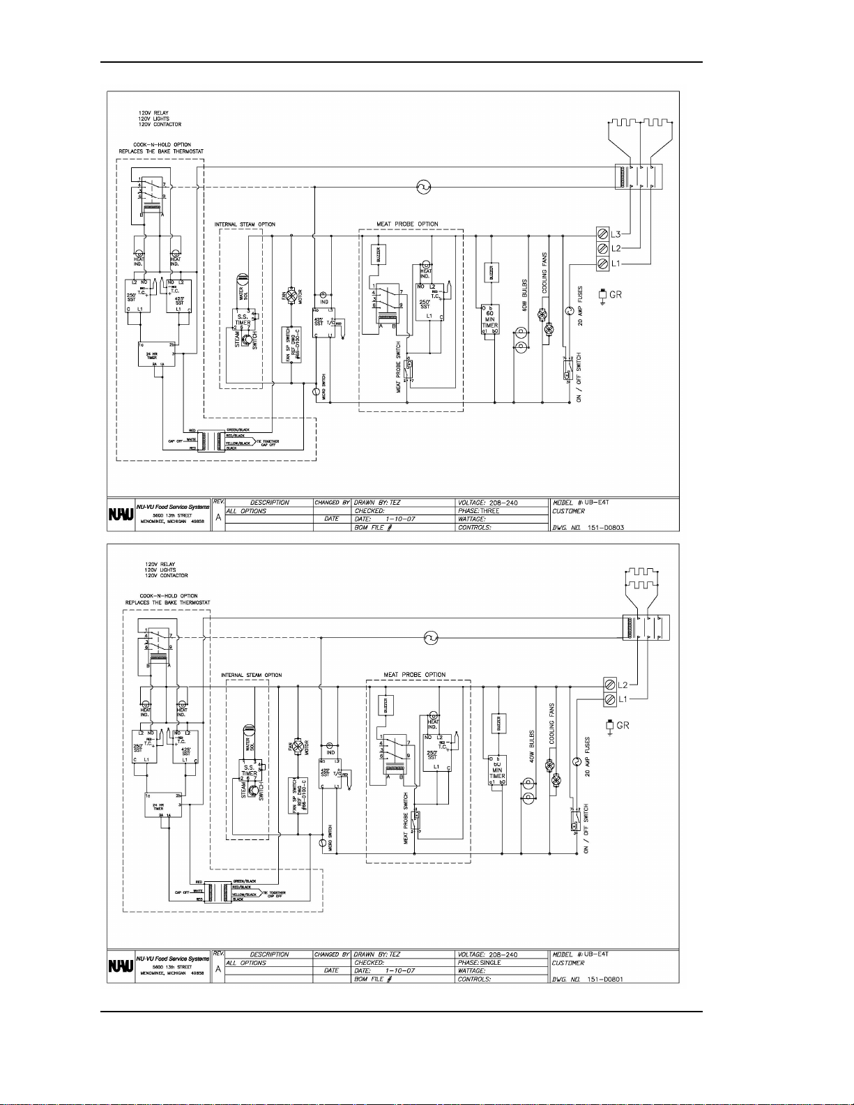
REPLACEMENT PARTS LIST UB–E3/9, –E4/8 & –E4T OWNER'S MANUAL
NU–VU® FOOD SERVICE SYSTEMS MENOMINEE, MICHIGAN 49858
page 32 SALES FAX (906) 863-5889 • SERVICE FAX (906) 863-6322 (906) 863-4401
Page 35

UB–E3/9, –E4/8 & –E4T OWNER'S MANUAL REPLACEMENT PARTS LIST
NU–VU® FOOD SERVICE SYSTEMS MENOMINEE, MICHIGAN 49858
(906) 863-4401 SALES FAX (906) 863-5889 • SERVICE FAX (906) 863-6322 page 33
Page 36
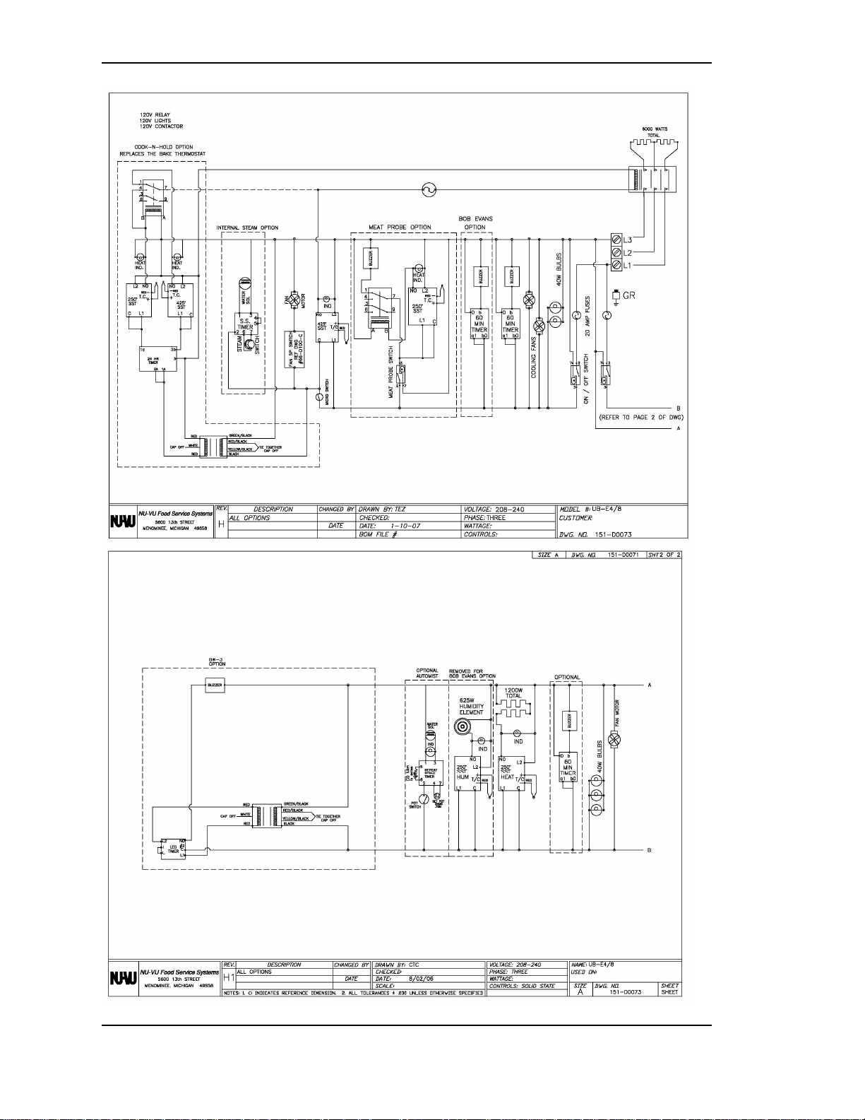
REPLACEMENT PARTS LIST UB–E3/9, –E4/8 & –E4T OWNER'S MANUAL
NU–VU® FOOD SERVICE SYSTEMS MENOMINEE, MICHIGAN 49858
page 34 SALES FAX (906) 863-5889 • SERVICE FAX (906) 863-6322 (906) 863-4401
 Loading...