

Page 1

Humidity Sensing Fan
Ventilateur de détection d’humidité
Model number:
Numéro de modèle :
INSTALLATION AND
USE & CARE INSTRUCTIONS
DIRECTIVES D’INSTALLATION,
AERN110S
D’UTILISATION ET D’ENTRETIEN
English - See page 2
Français - Voir page 9
© 2017 Broan Canada
99045948A
Page 2
Please visit our website - www.nutone.ca
to register this product and to view installation tips and videos.
Installer: Leave this manual with the homeowner.
READ AND SAVE THESE INSTRUCTIONS
INSTALLATION AND USE & CARE INSTRUCTIONS
SAFETY
WARNING
To reduce the risk of fire, electric
shock, or injury to persons, observe the
following:
• Use this unit only in the manner intended
by the manufacturer. If you have
questions, contact the manufacturer at
the address or telephone number listed in
the warranty.
• Before servicing or cleaning unit,
switch power off at service panel and
lock the service disconnecting means
to prevent power from being switched
on accidentally. When the service
disconnecting means cannot be locked,
securely fasten a prominent warning
device, such as a tag, to the service
panel.
• Installation work and electrical wiring
must be done by a qualified person(s)
in accordance with all applicable codes
and standards, including fire-rated
construction codes and standards.
• Sufficient air is needed for proper
combustion and exhausting of gases
through the flue (chimney) of fuel burning
equipment to prevent backdrafting. Follow
the heating equipment manufacturer’s
guideline and safety standards such
as those published by the National
Fire Protection Association (NFPA),
and the American Society for Heating,
Refrigeration and Air Conditioning
Engineers (ASHRAE), and the local code
authorities.
• When cutting or drilling into wall or ceiling,
do not damage electrical wiring and other
hidden utilities.
• Ducted fans must always be vented to
the outdoors.
• If this unit is to be installed over a tub or
shower, it must be marked as appropriate
for the application and be connected to a
GFCI (Ground Fault Circuit Interrupter) protected branch circuit.
• This unit must be grounded.
• Some metal edges and/or corners may
be sharp. Use of gloves during installation
and removal is recommended.
CAUTION
• For general ventilating use only. Do not
use to exhaust hazardous or explosive
materials and vapors.
• For installation in flat ceilings only. DO
NOT MOUNT THIS PRODUCT IN A
WALL.
• To avoid motor bearing damage and
noisy and/or unbalanced impellers, keep
drywall spray, construction dust, etc. off
power unit.
• DO NOT TOUCH THE HUMIDITYSENSING CIRCUIT BOARD.
Electrostatic discharge may damage the
circuit board.
• Please read specification label on
product for further information and
requirements.
2
Page 3
CLEANING & MAINTENANCE
For quiet and efficient operation, long life, and
attractive appearance - lower or remove grille
and vacuum interior of unit with the dusting brush
attachment.
The motor is permanently lubricated and never needs
oiling. If the motor bearings are making excessive
or unusual noises, replace the blower assembly
(includes motor and impeller).
OPERATION
The humidity control and fan can be operated
separately. Use a 1- or 2-function wall control. Do
not use a dimmer switch to operate the humidity
control.
SENSOR OPERATION
This humidity-sensing fan uses a sophisticated
humidity sensor that responds to: (a) rapid to
moderate increases in humidity or (b) humidity above
a set-point. The humidity sensor may occasionally
turn the fan ON when environmental conditions
change.
MANUAL ON WITH TIMED OFF
This humidity sensing fan has an additional operation
feature. For odor or vapor control, the fan can be
energized by cycling the power switch. Once the fan
has been energized in this manner, it will remain on
for the set timer period.
To manually energize the fan:
1. If fan power switch is already ON, proceed to
Step 2; otherwise, turn power switch ON for more
than 1 second.
2. Turn fan power switch OFF for less than 1
second.
3. Turn fan power switch back ON and fan will turn
ON.
SENSOR CLEANING
The humidity sensor is mounted in the control housing. The
sensor will operate most reliably when cleaned occasionally
as follows:
1. Disconnect power at service entrance.
2. Remove the grille. Use a dry dustcloth, clean toothbrush,
or lightly vacuum to clean sensor and grille. DO NOT
USE ABRASIVE CLOTH, STEEL WOOL PADS, OR
SCOURING POWDERS.
3. DO NOT USE cleaning sprays, solvents, or water on or
near the sensor!
%HUMIDITY MINUTES
60
50
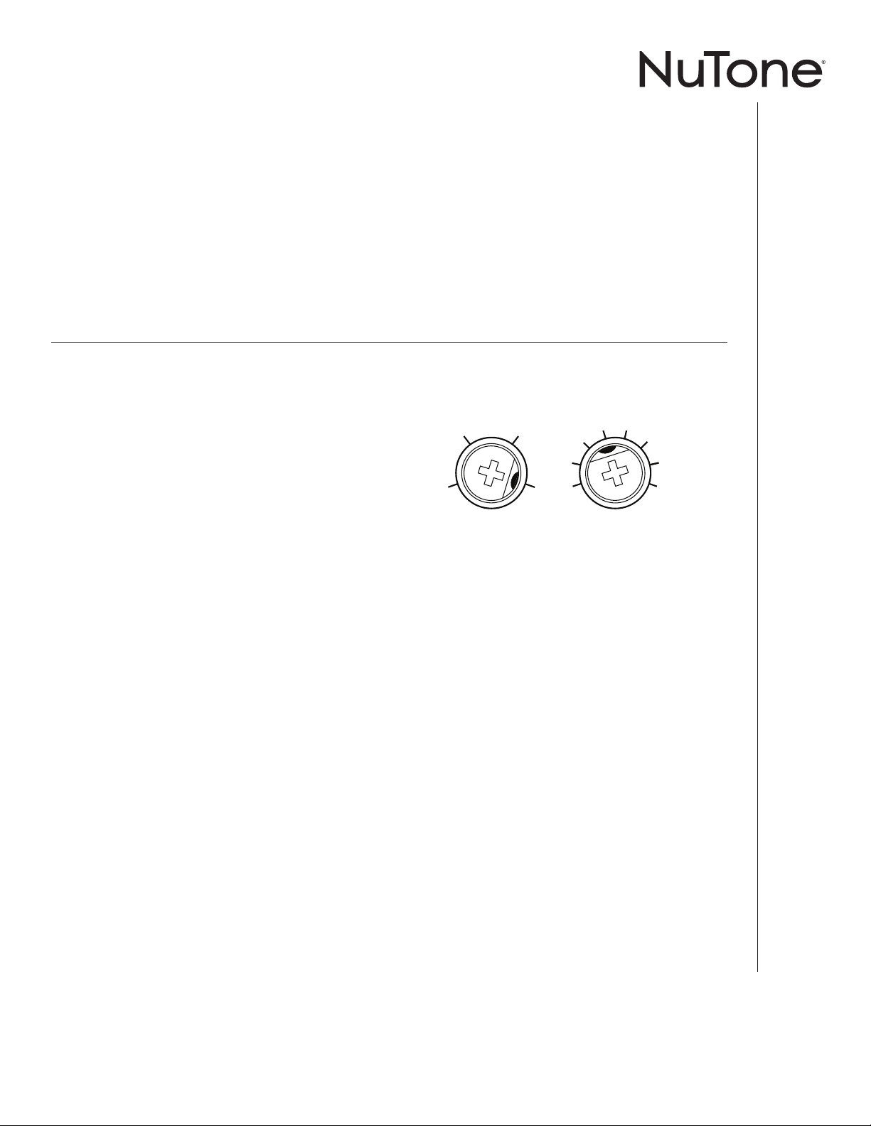
% HUMIDITY ADJUSTMENT
%HUMIDITY has been factory set at 80% for most
shower applications. If fan is not responding to changing
humidity conditions, adjust toward 50%. If fan is
responding too often to changing humidity conditions,
adjust toward 80%. If fan is still responding too often at
80%, contact NuTone Technical Support.
To adjust the %HUMIDITY:
1. Turn power off at electrical service panel.
2. Use a small screwdriver to carefully rotate
%HUMIDITY control to desired level.
3. Turn power on.
4. Repeat above steps if necessary.
MINUTES ADJUSTMENT (TIMER)
This humidity-sensing fan has a timer that controls how
long the fan remains on after (a) rise in humidity and
(b) humidity level are both below the user-adjustable
%HUMIDITY setting, or after being energized by cycling
power switch.
To adjust the timer:
1. Disconnect power at electrical service panel.
2. Use a small screwdriver to carefully rotate MINUTES
control to increase or decrease time.
3. Turn power on.
4. Repeat above steps if necessary.
70
80
Factory settings shown.
15
10
5
20 30
40
50
60
INSTALLATION AND USE & CARE INSTRUCTIONS
OPERATION
3
Page 4
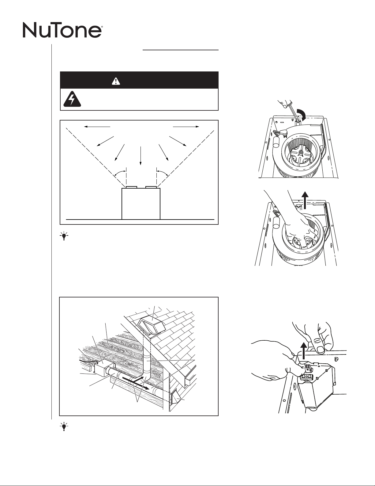
ALL INSTALLATIONS
COOKING AREA
Start here.
WARNING
• Disconnect the electrical power supply and lock
out the service panel.
Do not install above or
inside this area.
1. Remove blower and all
packing material from fan
housing.
INSTALLATION AND USE & CARE INSTRUCTIONS
NOT FOR USE IN
A COOKING AREA.
45
o
Cooking
Equipment
45
o
Floor
IMPORTANT - The ducting from this fan to the outside
of the building has a strong effect on the air flow, noise and
energy use of the fan. Use the shortest, straightest duct routing
possible for best performance, and avoid installing the fan with
smaller ducts than recommended. Insulation around the ducts
can reduce energy loss and inhibit mold growth. Fans installed
with existing ducts may not achieve their rated airflow.
ROOF CAP * (with built-in damper)
INSULATION
(Place around and
over fan housing.)
FAN
HOUSING
POWER
CABLE
*
Seal gaps
around
housing.
4-IN. ROUND
DUCT
*
Purchase separately.
*
Seal duct joints
with tape.
OR
4-IN. ROUND
ELBOWS
*
INSTALLATION
Keep duct
runs short.
WALL CAP
(with built-in
damper)
2. Remove wiring panel from
fan housing.
*
4
OPTION - To mount housing anywhere between ceiling
framing: Use optional Hanger Bar Kit (sold separately from local
distributors or website). Follow mounting instructions included
with kit.
Page 5
NEW CONSTRUCTION
For Retrofit Installation - Skip to Page 6.
3. Attach damper/duct connector
to fan housing.
Push connector through opening from inside of housing.
Engage tabs and secure with screw from parts bag.
TABS
4. Mount housing to ceiling
structure.
5. Connect 4-in. round duct.
6. Connect wiring.
Bend tab to expose desired access hole. Connect
power cable to housing with appropriate UL approved
connector. Connect wires per diagram on page 8. Reinstall wiring panel and secure with screw from parts
bag.
Make sure bottom of housing will be flush with finished
ceiling.
For proper location using ½-inch ceiling material: Bend
out housing tabs to fit against bottom of structure.
Secure housing through mounting ears with
appropriate fasteners.
If mounting housing to I-joist, use wood blocking as
shown.
HOUSING
TABS
INSTALLATION AND USE & CARE INSTRUCTIONS
INSTALLATION
5
Page 6

7. Install blower.
Re-install blower. Secure blower with 2 screws from parts
bag and plug blower into black receptacle. Plug in humiditysensing control.
CAUTION
• Make sure that the wiring inside of
the housing does not interfere with
re-installation of the blower.
Push grille up against ceiling.
RETROFIT
3. Remove old fan.
Enlarge ceiling opening (if necessary) to 9¾-inches )
(parallel to joist) by 10½-inches (perpendicular to joist).
Leave ductwork and wiring in place.
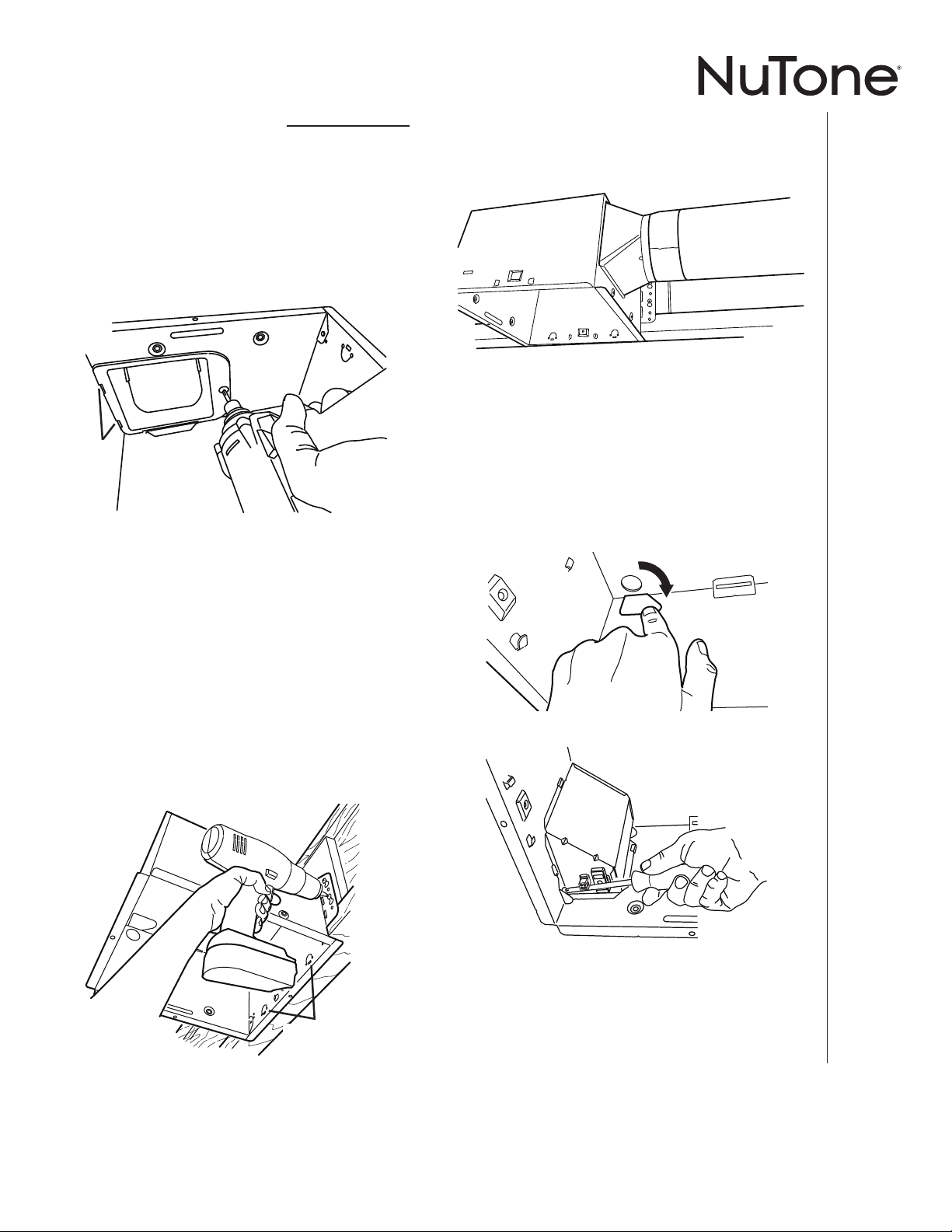
8. Install housing mask.
Place mask into housing
opening to
prevent drywall
spray and
construction dust
from damaging
blower.
Leave this mask in place to prevent
construction dust, drywall spray, or paint
from damaging inside of product.
REMOVE MASK BEFORE
INSTALLING GRILLE.
Laissez ce masque en place pour empêcher
la poussière de construction, le plâtre ou la
peinture, etc. d’endommager
l’intérieur du produit.
ENLEVEZ CE MASQUE AVANT
D’INSTALLER LA GRILLE.
Deje esta cubierta en su lugar para evitar
que polvos de construcción, rocíos de yeso
o pintura dañen el interior del producto.
QUITE LA CUBIERTA ANTES
DE INSTALAR LA REJILLA.
99352432A
9. Finish ceiling, remove mask,
then install grille.
Remove mask from housing. Squeeze grille springs
and insert into slots in housing.
1
2
4. Fold mounting ears flat against
housing.
INSTALLATION AND USE & CARE INSTRUCTIONS
6
INSTALLATION
Page 7

5. Connect wiring.
Bend tab to expose desired access hole. Connect
power cable to housing with appropriate UL approved
connector. Connect wires per diagram on page 8. Reinstall wiring panel and secure with screw from parts
bag.
7. Connect 4-in. round duct.
Pull existing ducting through housing discharge
opening.
Attach and tape ducting to duct connector.
Push connector/ducting back through opening.
Engage tabs and secure with screw from parts
bag.
3
1
2
6. Mount housing to ceiling
structure.
Mount housing to ceiling structure with standard
drywall or wood screws in 3 locations shown. The
humidity control panel assembly must be removed to
access one of the locations.
TABS
4
Install blower. Finish ceiling, then
install grille.
See Steps 7, 8 & 9 on Page 6.
(Step 8 is only necessary in RETROFIT
installations if ceiling requires repair.)
INSTALLATION AND USE & CARE INSTRUCTIONS
INSTALLATION
CAUTION
• DO NOT TOUCH THE HUMIDITYSENSING CIRCUIT BOARD.
Electrostatic discharge may damage
the circuit board.
7
Page 8

WIRING DIAGRAMS
ON / OFF SWITCH
(PURCHASE SEPARATELY)
ON / OFF
SWITCH
120
VAC
LINE
IN
SWITCH BOX
WHT
GRD
BLK
WHT
UNIT
GREY
BLK
WHT
GRD
WHT
BLK
WHT
BRN
HUMIDITY
CONTROL
FAN
120
VAC
LINE
IN
SWITCH BOX
WHT
GRD
WHT
UNIT
BLK
WHT
GRD
WHT
BLK
WHT
HUMIDITY
CONTROL
FAN
RED
BLK
GREY
BRN
2-FUNCTION CONTROL
(PURCHASE SEPARATELY)
COM
(1)
HUMIDITY
CONTROL
(AUTO/OFF)
(2)
FAN
(ON/OFF)
WIRING OPTION #1
• When switch is ON, fan will operate automatically, based on room humidity conditions.
• Turn fan ON immediately for the set timer period
(to control odors), by cycling switch.
WIRING OPTION #2
• When first switch (1) is ON, fan will operate automatically based on room humidity conditions.
• Turn fan ON immediately (to control odors) by using
second switch (2).
INSTALLATION AND USE & CARE INSTRUCTIONS
INSTALLATION
8
Page 9

Veuillez visiter site Web – www.nutone.ca
pour enregistrer ce produit et voir des conseils et vidéos d’installation.
Installateur : Veuillez remettre ce manuel au propriétaire.
LIRE CES DIRECTIVES ET LES CONSERVER
AVERTISSEMENT
Observez les directives ci-dessous afin
de réduire les risques d’incendie, de choc
électrique ou de blessures corporelles :
• N’utilisez cet appareil que de la manière prévue
par le fabricant. Si vous avez des questions,
communiquez avec le fabricant à l’adresse
ou au numéro de téléphone indiqués dans la
garantie.
• Avant de procéder à l’entretien ou au nettoyage
de l’appareil, coupez l’alimentation du panneau
électrique et verrouillez l’interrupteur principal
afin d’empêcher que le courant ne soit
accidentellement rétabli. S’il est impossible
de verrouiller l’interrupteur principal, fixez
solidement un message d’avertissement,
par exemple une étiquette, sur le panneau
électrique.
• La pose de l’appareil et les travaux d’électricité
doivent être effectués par des personnes
qualifiées conformément à la réglementation
en vigueur, notamment les normes de la
construction ayant trait à la protection contre les
incendies.
• Pour éviter les refoulements, l’apport d’air doit
être suffisant pour brûler les gaz produits par
les appareils à combustion et les évacuer dans
le conduit de fumée (cheminée). Respectez les
directives du fabricant de l’appareil de chauffage
et les normes de sécurité, notamment celles
publiées par la National Fire Protection
Association (NFPA), l’American Society for
Heating, Refrigeration and Air Conditioning
Engineers (ASHRAE) et les codes des autorités
locales.
• Veillez à ne pas endommager le câblage
électrique ou d’autres équipements non
apparents lors de la découpe ou du perçage du
mur ou du plafond.
• Les ventilateurs canalisés doivent toujours
rejeter l’air à l’extérieur.
• Si cet appareil doit être installé au-dessus de
la baignoire ou de la douche, il doit porter une
indication attestant qu’il convient à cet usage
lorsqu’il est relié à un circuit protégé par un
disjoncteur de fuite à la terre (DDFT).
• Cet appareil doit être relié à une mise à la terre.
• Certains coins ou arêtes métalliques peuvent être
tranchants. Il est recommandé de porter des gants
lors de l’installation et du démontage.
ATTENTION
• Pour ventilation générale
uniquement. N’utilisez pas
cet appareil pour évacuer
des matières ou des vapeurs
dangereuses ou explosives.
• Pour installation dans un plafond
plat uniquement. NE PAS
MONTER CE PRODUIT DANS
UN MUR.
• Pour éviter d’endommager
les roulements du moteur, de
déséquilibrer les pales ou de les
rendre bruyantes, débarrassez
l’appareil de la poussière de
plâtre, de construction, etc.
• NE TOUCHEZ PAS AU CIRCUIT
DU DÉTECTEUR D’HUMIDITÉ.
Une décharge électrostatique
pourrait endommager le circuit.
• Veuillez lire l’étiquette de
spécifications du produit pour
obtenir plus de renseignements,
notamment sur les exigences.
DIRECTIVES D’INSTALLATION, D’UTILISATION ET D’ENTRETIEN
SÉCURITÉ
9
Page 10

NETTOYAGE ET ENTRETIEN
Pour un fonctionnement silencieux et efficace,
ainsi qu’une durabilité et une apparence
supérieures, abaissez ou enlevez la grille et
nettoyez l’intérieur de l’appareil avec un aspirateur
muni d’une brosse à épousseter.
Le moteur est lubrifié en permanence et n’a pas
besoin d’être huilé. Si les roulements du moteur
sont anormalement bruyants, remplacez l’ensemble
de ventilateur (incluant le moteur et la roue à
ailettes).
FONCTIONNEMENT
Le contrôle d’humidité et le ventilateur
fonctionnent indépendamment l’un de l’autre.
Utilisez une commande murale à 1 ou
2fonctions. N’utilisez pas un gradateur pour
commander le contrôle d’humidité.
FONCTIONNEMENT DU DÉTECTEUR
Ce ventilateur utilise un détecteur d’humidité
perfectionné qui réagit à : (a) une augmentation
rapide à modérée du taux d’humidité ou (b)
un taux d’humidité établi comme point de
consigne. Le détecteur d’humidité pourra
occasionnellement mettre le ventilateur en
marche si les conditions environnementales
changent.
MISE EN MARCHE MANUELLE AVEC
ARRÊT DIFFÉRÉ
Ce ventilateur à détecteur d’humidité est doté
d’une autre fonction. Pour le contrôle des
odeurs ou des vapeurs, le ventilateur peut être
mis en marche en tournant le commutateur.
Lorsque le ventilateur est actionné de cette
façon, il reste en marche pendant la période
réglée par la minuterie.
Pour actionner manuellement le ventilateur :
1. Si le commutateur du ventilateur est déjà
sur Marche, passez à l’étape 2; sinon,
placez le commutateur sur Marche pendant
plus d’une seconde.
2. Tournez le commutateur du ventilateur sur
Arrêt pendant moins d’une seconde.
3. Remettez le commutateur du ventilateur sur
DIRECTIVES D’INSTALLATION, D’UTILISATION ET D’ENTRETIEN
FONCTIONNEMENT
Marche et celui-ci se mettra en marche.
NETTOYAGE DU CAPTEUR
Le capteur d’humidité est installé dans le boîtier de la
commande. Pour un fonctionnement optimal du capteur, le
nettoyer à l’occasion de la façon suivante :
1. Débrancher l’alimentation électrique du ventilateur.
2. Retirer la grille. Pour nettoyer la grille et le capteur :
utiliser un chiffon sec, une brosse à dents propre ou
passer légèrement l’aspirateur. NE PAS UTILISER UN
CHIFFON ABRASIF, DE LA LAINE D’ACIER OU UNE
POUDRE À RÉCURER.
3. NE PAS UTILISER de vaporisateurs nettoyants, de
solvants ou de l’eau sur ou près du capteur!
%HUMIDITY MINUTES
60
50
RÉGLAGE DU % D’HUMIDITÉ
Le pourcentage d’humidité %HUMIDITY a été fixé à l’usine à 80
% afin de convenir à la plupart des applications avec douche. Si le
ventilateur ne répond pas à l’évolution des conditions d’humidité,
réglez vers 50%. Si le ventilateur répond trop souvent à l’évolution
des conditions d’humidité, réglez vers 80%. Si le ventilateur
répond encore trop souvent à 80%, contacter le support technique
NuTone.
Pour régler l’humidité %HUMIDITY :
1. Coupez le courant sur le panneau d’alimentation électrique.
2. À l’aide d’un petit tournevis, tournez délicatement contrôle de
%HUMIDITY au niveau désiré.
3. Rétablissez le courant.
4. Répétez les étapes ci-dessus au besoin.
RÉGLAGE DES MINUTES (MINUTERIE)
Ce ventilateur à détecteur d’humidité comporte une minuterie qui
contrôle combien de temps le ventilateur reste en marche après
(a) une hausse de l’humidité et (b) lorsque le taux d’humidité est
inférieur au taux %HUMIDITY réglé par l’utilisateur, ou après que
celui-ci ait actionné le commutateur.
Pour régler la minuterie :
1. Coupez le courant sur le panneau d’alimentation électrique.
2. À l’aide d’un petit tournevis, tournez délicatement les
MINUTES pour augmenter ou diminuer la durée.
3. Rétablissez le courant.
4. Répétez les étapes ci-dessus au besoin.
Réglages effectués à l’usine illustrés.
70
80
15
10
5
20 30
40
50
60
10
Page 11

TOUS LES TYPES DE POSE
Commencez ici.
AVERTISSEMENT
• Couper l’alimentation électrique et verrouiller le
panneau de service.
ZONE DE CUISSON
Ne pas installer au-dessus ou à
l'intérieur de cette zone.
1. Retirez le ventilateur et tout
le matériel d’emballage du
boîtier du ventilateur.
NE PAS INSTALLER DANS
UNE ZONE DE CUISSON.
45
o
Appareil
de cuisson
45
o
Plancher
IMPORTANT - Les conduits allant de ce ventilateur jusqu’à
l’extérieur de l’habitation ont une grande influence sur le débit
d’air, le bruit du ventilateur et sa consommation d’énergie. Pour
obtenir le meilleur rendement, utilisez les conduits les plus courts
et les plus droits que possible et évitez d’utiliser des conduits
plus petits que ceux recommandés. L’isolation des conduits peut
contribuer à réduire les pertes d’énergie et éviter la prolifération
de moisissures. Les ventilateurs installés sur d’anciens conduits
pourraient ne pas produire leur débit d’air nominal.
CAPUCHON DE TOIT* (avec clapet intégré)
OU
CAPUCHON
COUDES RONDS
DE 10 CM (4 PO)*
(avec clapet intégré)
Utilisez des
conduits les
plus courts
possible.
MURAL*
VENTILATEUR
D'ALIMENTATION*
CÂBLE
Scellez
l'écart autour
du boîtier.
CONDUIT
ROND* DE
10 CM (4 PO)
*Vendu séparément.
ISOLANT (Le placer sur
le boîtier de ventilateur
et autour.)
BOÎTIER DE
Scellez les joints
avec du ruban à conduit.
DIRECTIVES D’INSTALLATION, D’UTILISATION ET D’ENTRETIEN
2. Enlevez le panneau de
câblage du boîtier du
ventilateur.
INSTALLATION
OPTION - Pour installer le boîtier n’importe où entre les
solives du plafond : Utilisez l’ensemble de barres de suspension
offert en option (vendu séparément chez votre distributeur local
ou site Web). Suivez les instructions accompagnant l’ensemble.
11
Page 12

CONSTRUCTION NEUVE
Pour une rénovation - passez à la page 13.
3. Fixez le clapet/raccord de
conduit au boîtier de ventilateur.
Poussez le raccord au travers de l’ouverture par
l’intérieur du boîtier. Engagez les ergots et fixez le tout
avec les vis se trouvant dans le sachet de pièces.
ERGOTS
4. Montage du boîtier à la
charpente du plafond.
5. Connectez un conduit rond de
10 cm (4 po).
6. Branchez les fils.
Repliez la languette pour exposer le trou d’accès
voulu. Fixez le câble d’alimentation au boîtier à l’aide
du connecteur approprié homologué UL. Connecter
les fils par schéma à la page 15. Reposez le panneau
de câblage et fixez-le avec les vis se trouvant dans le
sachet de pièces.
DIRECTIVES D’INSTALLATION, D’UTILISATION ET D’ENTRETIEN
Assurez-vous que le dessous du boîtier affleure la
surface finie du plafond.
Pour un positionnement adéquat avec une surface
de plafond de 13 mm (½ po) : Repliez les ergots vers
l’extérieur du boîtier pour les appuyer contre le dessous
de la charpente.
Fixez le boîtier au travers des oreilles de montage à
l’aide des fixations appropriées.
Si vous fixez le boîtier à une poutrelle en « I », utilisez un
bloc de bois comme illustré.
INSTALLATION
ERGOTS
DU
BOÎTIER
12
Page 13

7. Installez le ventilateur.
Reposez le ventilateur. Fixez-le avec 2 vis du
sachet de pièces et branchez-le dans la prise noire.
Branchez le contrôle de l’humidité de détection.
ATTENTION
• Assurez-vous que le câblage à
l’intérieur du boîtier n’empêche pas
de remettre le ventilateur en place.
Poussez la
grille contre le
plafond.
RÉNOVATION
3. Enlevez l’ancien ventilateur.
Agrandissez l’ouverture (si nécessaire) à 24,7 cm
(9¾ po) (parallèle aux solives) par 26,7 cm (10½ po)
(perpendiculaire aux solives). Laissez les conduits et le
câblage électrique en place.
8. Installez le masque
du boîtier.
Placez le
masque sur
l’ouverture
du boîtier pour
empêcher la
poussière de plâtre
et de construction
d’abîmer le ventilateur.
Leave this mask in place to prevent
construction dust, drywall spray, or paint
from damaging inside of product.
REMOVE MASK BEFORE
INSTALLING GRILLE.
Laissez ce masque en place pour empêcher
la poussière de construction, le plâtre ou la
peinture, etc. d’endommager
l’intérieur du produit.
ENLEVEZ CE MASQUE AVANT
D’INSTALLER LA GRILLE.
Deje esta cubierta en su lugar para evitar
que polvos de construcción, rocíos de yeso
o pintura dañen el interior del producto.
QUITE LA CUBIERTA ANTES
DE INSTALAR LA REJILLA.
99352432A
9. Finissez le plafond, retirez le
masque, puis installez la grille.
Retirez le masque du boîtier. Pincez les ressorts de la
grille set insérez-les dans les fentes du boîtier.
1
2
4. Pliez les oreilles de montage
à plat contre le boîtier.
DIRECTIVES D’INSTALLATION, D’UTILISATION ET D’ENTRETIEN
INSTALLATION
13
Page 14

5. Branchez les fils.
Repliez la languette pour exposer le trou d’accès
voulu. Fixez le câble d’alimentation au boîtier à l’aide
du connecteur approprié homologué UL. Connecter
les fils par schéma à la page 15. Reposez le panneau
de câblage et fixez-le avec les vis se trouvant dans le
sachet de pièces.
7. Connectez un conduit rond de
10 cm (4 po).
Tirez le conduit existant au travers de l’ouverture
de sortie du boîtier.
Fixez le conduit au raccord et appliquez du ruban
adhésif sur le joint.
Repoussez le raccord/conduit au travers de
l’ouverture.
Engagez les ergots et fixez le tout avec les vis se
trouvant dans le sachet de pièces.
3
1
2
DIRECTIVES D’INSTALLATION, D’UTILISATION ET D’ENTRETIEN
6. Fixez le boîtier à la charpente du
plafond.
Fixez le boîtier à la charpente du plafond avec des vis à
cloison sèche ou des vis à bois ordinaires aux 3 endroits
indiqués. L’assemblage du panneau de contrôle de
l’humidité doit être enlevée pour accéder à l’un des
emplacements.
INSTALLATION
ATTENTION
ERGOTS
4
Installez le ventilateur. Finissez le
plafond, puis installez la grille.
Voir les étapes 7, 8 et 9 à la page 13.
(L’étape 8 n’est nécessaire que pour les
installations avec RÉNOVATION si le plafond
doit être réparé.)
14
• NE TOUCHEZ PAS AU CIRCUIT
DU DÉTECTEUR D’HUMIDITÉ. Une
décharge électrostatique pourrait
endommager le circuit.
Page 15

SCHÉMAS DE CÂBLAGE
COMMUTATEUR
(MARCHE/ARRÊT)
(VENDUE SÉPARÉMENT)
ENTRÉE
120
VCA
BOÎTE D'INTERRUPTEUR
BLC
TERRE
NOIR
BLC
APPAREIL
GRIS
NOIR
BLC
TERRE
BLC
NOIR
BLC
BRUN
CONTRÔLE
D’HUMIDITÉ
VENTILATEUR
COMMUTATEUR
(MARCHE/ARRÊT)
ENTRÉE
120
VCA
BOÎTE D'INTERRUPTEUR
BLC
BLC
APPAREIL
NOIR
BLC
TERRE
BLC
NOIR
BLC
CONTRÔLE
D’HUMIDITÉ
VENTILATEUR
NOIR
GRIS
BRUN
COMMANDE À 2 FONCTIONS MODÈLE 68W
(VENDUE SÉPARÉMENT)
COM
(1)
CONTRÔLE
D’HUMIDITÉ
(AUTO / ARRÊT)
(2)
ÉCLAIRAGE
(MARCHE / ARRÊT)
ROUGE
TERRE
CÂBLAGE OPTION # 1
• Lorsque commutateur est ON, ventilateur
fonctionne automatiquement, en fonction des
conditions d’humidité ambiante.
• Tournez ventilateur ON immédiatement pour la
période réglage de la minuterie (pour contrôler les
odeurs), par le vélo de commutateur.
CÂBLAGE OPTION # 2
• Lorsque premier commutateur (1) est ON, le ventilateur fonctionne automatiquement en fonction des
conditions d’humidité ambiante.
• Tournez ventilateur ON immédiatement (pour contrôler les odeurs) en utilisant second commutateur
(2).
DIRECTIVES D’INSTALLATION, D’UTILISATION ET D’ENTRETIEN
INSTALLATION
15
Page 16

16
 Loading...