

Page 1
AM/FM
RADIO/CD PLAYER
INTERCOM SYSTEM
MODEL: IMA-4406 SERIES MASTER STATION
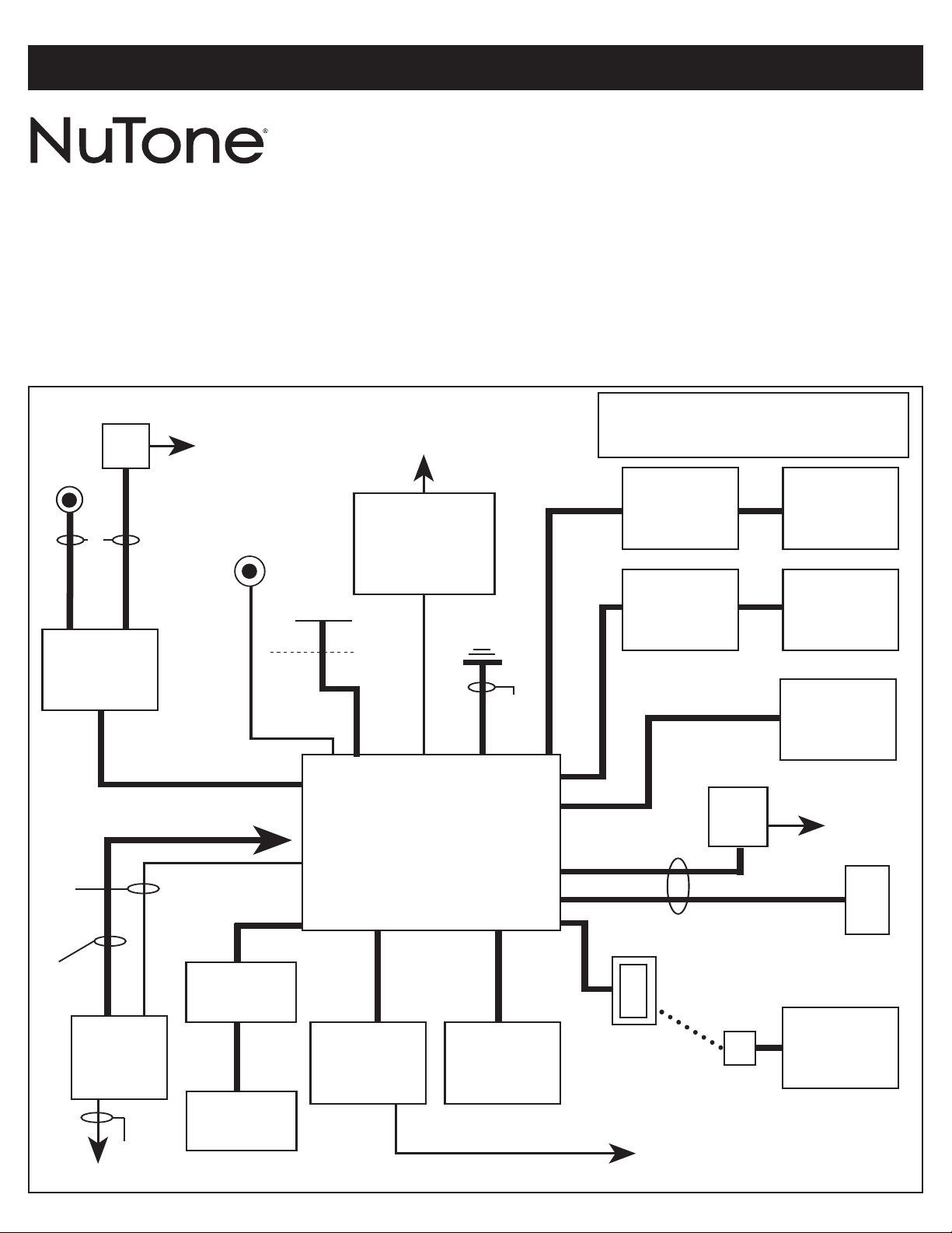
IMA-4406 SERIES REPRESENTATIVE WIRING ILLUSTRATION
To register this product, visit www.nutone.com
INSTALLATION
INSTRUCTIONS
This booklet contains information for installing the master
station. All system wiring and rough-in frames should be
installed before mounting and wiring the master station.
Refer to the installation instructions packaged with the
rough-in frames for detailed wiring information. For more
detailed information on wiring and mounting other system
components (i.e., speaker, remote control, etc.), refer to the
installation instructions packaged with each separate
component.
NUTONE CHIME
TRANSFORMER
PUSHBUTTON
OPTIONAL
ELECTRONIC
DOOR CHIME
200´ MAX
NUTONE
IW-2
14 GA
GROUND
SHIELDED
AUDIO
CABLES
OPTIONAL
SOURCE
120V 60HZ
(CLASS 1)
(OBSERVE
LOCAL CODE)
PUSHBUTTON FOR
OPTIONAL CHIME
MODULE
18/2 (NUTONE S-143)
MUSIC
DISTRIBUTION
VOLUME
CONTROL
MUSIC
MUSIC
DISTRIBUTION
SPEAKER
120V. 60HZ (CLASS 1)
(OBSERVE LOCAL CODE)
300´ MAX
NUTONE IW-2
IW-2
IW-2
ANTENNA
ATTIC
14/2 WITH GROUND
(OBSERVE LOCAL CODES)
120V 60HZ (CLASS 1)
(2) 801T
TRANSFORMERS
SECONDARY:
18V, 72VA
INSIDE
IMA-4406
MASTER STATION
IW-2
NUTONE
DOOR
SPEAKER
EARTH
GROUND
14 GA
IW-6
NUTONE
5˝ PATIO
SPEAKER
W/CONTROLS
300´ MAX
NUTONE
IW-6
NUTONE IW-6
100´ MAX S-143
100´ MAX S-143
IA-6C
RECEPTACLE
Use this diagram for reference only.
See IR-105 Rough-in frame instructions
for detailed wiring.
OUTSIDE
REMOTE
CONTROL
INSIDE
REMOTE
CONTROL
IW-6
TRANSFORMER
OPTIONAL WIRING
FOR DOOR
RELEASE
DOOR SPEAKER MODELS WITH CHIME
PUSHBUTTON ALSO REQUIRE 18/2 (S-143)
TO CHIME LOCATION OR IW-2 TO MASTER
IF CHIME MODULE IS USED.
IW-2
301T
IA-6
PLUG
IW-2
SPEAKERS
W/CONTROLS
FRAME WITH 5˝
OUTSIDE
SPEAKER
INSIDE
SPEAKER
INSIDE
120V 60HZ
(CLASS 1)
(OBSERVE
LOCAL CODE)
DR-1/DR-2
DOOR RELEASE
DESKTOP
REMOTE
Page 2

INSTALLATION
TABLE OF CONTENTS
INSTALLATION PAGE
Contents of Carton . . . . . . . . . . . . . . . . . . . . . . . . . . . . . . . . . . . . . . . . . . . . . . . . . . . . . . . . . . . . . . . . . . . . . . . . . . . . .3
Precautions and Guidelines . . . . . . . . . . . . . . . . . . . . . . . . . . . . . . . . . . . . . . . . . . . . . . . . . . . . . . . . . . . . . . . . . . . . . .3
Wiring Specifications . . . . . . . . . . . . . . . . . . . . . . . . . . . . . . . . . . . . . . . . . . . . . . . . . . . . . . . . . . . . . . . . . . . . . . . . . . .3
Remote Station Wiring . . . . . . . . . . . . . . . . . . . . . . . . . . . . . . . . . . . . . . . . . . . . . . . . . . . . . . . . . . . . . . . . . . . . . . . . . .3
Maximum Number of Remote Stations . . . . . . . . . . . . . . . . . . . . . . . . . . . . . . . . . . . . . . . . . . . . . . . . . . . . . . . . . . . . . .3
Mounting the Terminal Board . . . . . . . . . . . . . . . . . . . . . . . . . . . . . . . . . . . . . . . . . . . . . . . . . . . . . . . . . . . . . . . . . . . . .4
Connecting the Remote Wiring . . . . . . . . . . . . . . . . . . . . . . . . . . . . . . . . . . . . . . . . . . . . . . . . . . . . . . . . . . . . . . . . . . . .4
Connecting Volume Control Wiring . . . . . . . . . . . . . . . . . . . . . . . . . . . . . . . . . . . . . . . . . . . . . . . . . . . . . . . . . . . . . . . .5
Connecting Door Speaker Wiring . . . . . . . . . . . . . . . . . . . . . . . . . . . . . . . . . . . . . . . . . . . . . . . . . . . . . . . . . . . . . . . . . .5
Preparing Master Station Panel for Optional Door Release Pushbutton . . . . . . . . . . . . . . . . . . . . . . . . . . . . . . . . . . . .5
Mounting the Optional Chime Module in the Master Station Panel . . . . . . . . . . . . . . . . . . . . . . . . . . . . . . . . . . . . . .5, 6
Mounting the Master Station . . . . . . . . . . . . . . . . . . . . . . . . . . . . . . . . . . . . . . . . . . . . . . . . . . . . . . . . . . . . . . . . . . . . . .6
Connecting the Power Transformers . . . . . . . . . . . . . . . . . . . . . . . . . . . . . . . . . . . . . . . . . . . . . . . . . . . . . . . . . . . . . . .7
Mounting the Transformer Cover . . . . . . . . . . . . . . . . . . . . . . . . . . . . . . . . . . . . . . . . . . . . . . . . . . . . . . . . . . . . . . . . . .7
Connecting the Master Station to the Terminal Board . . . . . . . . . . . . . . . . . . . . . . . . . . . . . . . . . . . . . . . . . . . . . . . . . .8
Connecting the Radio Antenna . . . . . . . . . . . . . . . . . . . . . . . . . . . . . . . . . . . . . . . . . . . . . . . . . . . . . . . . . . . . . . . . . . . .9
Connecting the Optional Chime Module . . . . . . . . . . . . . . . . . . . . . . . . . . . . . . . . . . . . . . . . . . . . . . . . . . . . . . . . . . . . .9
Connecting Optional Electronic Chime . . . . . . . . . . . . . . . . . . . . . . . . . . . . . . . . . . . . . . . . . . . . . . . . . . . . . . . . . . . . . .9
Connecting Optional Accessories . . . . . . . . . . . . . . . . . . . . . . . . . . . . . . . . . . . . . . . . . . . . . . . . . . . . . . . . . . . . . . . . .10
Connecting Power to the Optional CP-95 Cassette Player . . . . . . . . . . . . . . . . . . . . . . . . . . . . . . . . . . . . . . . . . . . . .10
Mounting and Connecting Optional Door Release Pushbutton . . . . . . . . . . . . . . . . . . . . . . . . . . . . . . . . . . . . . . . . . .11
Connecting the Memory Back Up Battery . . . . . . . . . . . . . . . . . . . . . . . . . . . . . . . . . . . . . . . . . . . . . . . . . . . . . . . . . .11
Securing the Master Panel . . . . . . . . . . . . . . . . . . . . . . . . . . . . . . . . . . . . . . . . . . . . . . . . . . . . . . . . . . . . . . . . . . . . . .11
Powering Up the System . . . . . . . . . . . . . . . . . . . . . . . . . . . . . . . . . . . . . . . . . . . . . . . . . . . . . . . . . . . . . . . . . . . . . . .11
OPERATIONAL CHECKOUT
System Operating Controls . . . . . . . . . . . . . . . . . . . . . . . . . . . . . . . . . . . . . . . . . . . . . . . . . . . . . . . . . . . . . . . . . . . . .12
Digital Clock . . . . . . . . . . . . . . . . . . . . . . . . . . . . . . . . . . . . . . . . . . . . . . . . . . . . . . . . . . . . . . . . . . . . . . . . . . . . . . . . .13
System Checkout . . . . . . . . . . . . . . . . . . . . . . . . . . . . . . . . . . . . . . . . . . . . . . . . . . . . . . . . . . . . . . . . . . . . . . . . . . . . .13
Setting Program Audio Controls . . . . . . . . . . . . . . . . . . . . . . . . . . . . . . . . . . . . . . . . . . . . . . . . . . . . . . . . . . . . . . .13, 14
Setting Intercom Volume . . . . . . . . . . . . . . . . . . . . . . . . . . . . . . . . . . . . . . . . . . . . . . . . . . . . . . . . . . . . . . . . . . . . . . .14
Setting Internal Intercom Volume Control . . . . . . . . . . . . . . . . . . . . . . . . . . . . . . . . . . . . . . . . . . . . . . . . . . . . . . . . . . .14
Setting the BEEP Tone Level
Setting the External Audio Source Level
Diagnostic Tests . . . . . . . . . . . . . . . . . . . . . . . . . . . . . . . . . . . . . . . . . . . . . . . . . . . . . . . . . . . . . . . . . . . . . . . . . . . . . .15
Resetting the Microprocessor . . . . . . . . . . . . . . . . . . . . . . . . . . . . . . . . . . . . . . . . . . . . . . . . . . . . . . . . . . . . . . . . . . . .
. . . . . . . . . . . . . . . . . . . . . . . . . . . . . . . . . . . . . . . . . . . . . . . . . . . . . . . . . . . . . . . . . . . .
. . . . . . . . . . . . . . . . . . . . . . . . . . . . . . . . . . . . . . . . . . . . . . . . . . . . . . . . . . .
14
14
15
INSTALLER’S TROUBLESHOOTNG GUIDE . . . . . . . . . . . . . . . . . . . . . . . . . . . . . . . . . . . . . . . . . . . . . .16, 17, 18
WARRANTY . . . . . . . . . . . . . . . . . . . . . . . . . . . . . . . . . . . . . . . . . . . . . . . . . . . . . . . . . . . . . . . . . . . . . . . . . . . . . . . . . . .20
2
Page 3

INSTALLATION
CONTENTS OF CARTON
Check (3) for the following IMA-4406 carton contents.
o IMA-4406 master station
o Terminal board
ransformer cover
o T
ardware bag assembly containing:
o H
2 - shoulder screws
12 - No. 6 x 3/8 screws
4 - colored panel mounting screws
4 - ‘L’ panel mounting brackets
o Homeowner’s manual with room labels
o Installation instructions
o Product Registration Warranty Card
NOTE TO INSTALLER: Do not discard these
installation instructions. Please transfer all
installation instructions, warranty registration
and homeowner’s manual to the homeowner.
PRECAUTIONS AND GUIDELINES
The NuTone IMA-4406 master station has been designed for
ease of installation. Please read and follow ALL installation
instructions, guidelines and precautions. Any deviation from
these instructions or miswiring combinations may result in
unit failure and void of warranty.
WARNING!
120 Volt AC Power to Transformers in the IR-105
Rough-in MUST Remain OFF until ALL System Wiring
at the Master and Remote Stations is Complete.
• Observe all local building regulatory codes in your area.
• All screw terminals at the master and remote stations must
be secure.
• Observe all color code connections of wires when
connecting the remote stations to the master.
• The IMA-4406 is designed to be installed with only NuTone
specified wire. No other wire should be used. The use of
wire other than NuTone wire will void all NuTone warranties
and may result in faulty installation and improper operation.
IMPORTANT WARNING!
THE POWER TRANSFORMER CONTAINS AN
INTERNAL FUSE.
DO NOT SHORT THE LOW VOLTAGE CONNECTING
SCREWS OF THE TRANSFORMER OR THE
TRANSFORMER WILL BE DESTROYED!
Use NuTone IW-2, 22 ga. twisted pair for connecting:
• Door speakers to master
• Remote controls to speakers
Speaker volume control (IC901) to master
•
• Speaker volume control (IC901) to speakers
• Electronic chime audio output to master
• Pushbutton to chime module
Use NuTone S-143, 18 ga. twisted pair for connecting:
• Pushbutton to electronic chime
• Electronic chime to chime transformer
Use Nº14/2 power cable with ground, Class 1 UL Listed
(Observe local codes) for connecting:
• Transformers to 120v AC
Use shielded audio cable for connecting external audio
sources to the master station.
REMOTE STATION WIRING
An individual 6-wire cable (IW-6) must be connected from
each remote station or remote control location to the master
station’s terminal board.
Maximum station wire length: 750 ft.
IMPORTANT! NuTone cannot be responsible for
improper system operation that results from
interference generated by light dimmers, fluorescent
lighting fixtures, and similar electrical products. Such
interference must be corrected at the source. TO HELP
REDUCE THIS INTERFERENCE, ALL WIRING
CONNECTIONS TO THE MASTER MUST BE PLACED
AT LEAST 12 INCHES FROM ANY AC POWER WIRING.
AVOID RUNNING INTERCOM WIRES PARALLEL TO
AC POWER WIRING.
Maximum total length of IW-6 cable per system: 4,000 ft.
MAXIMUM NUMBER OF REMOTE
STATIONS
The master station will accommodate up to 9 connections
at the terminal board. These connections can be any
combination of remote stations, remote controls or volume
NOTE:
station to a set of screw terminals.
NEVER connect more than one remote
WIRING SPECIFICA
See the IR-105 master rough-in frame installation instructions
for detailed wiring information.
Use NuTone IW-6, 3 twisted pair for connecting:
• Remote controls to master
• Remote stations to master
TIONS
controls. It will also accommodate 3 door speaker
connections.
If more than 9 stations are required, use the optional
Model Nº IAA-440 expansion kit. This will allow an additional
6 connections at the master.
3
Page 4
INSTALLATION (Continued)
2.
WARNING! NEVER EXCEED A TOTAL OF 15 NUTONE
25 OHM SPEAKERS ON THIS SYSTEM.
WARNING! NEVER USE STANDARD 8 OHM STEREO
PEAKERS ON THIS SYSTEM. USE ONLY NUTONE
S
SPECIFIED SPEAKERS ON THIS MASTER.
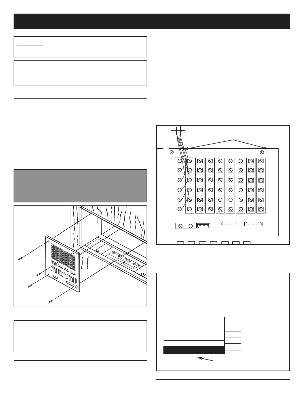
MOUNTING THE TERMINAL BOARD
1. Remove and clean any drywall debris or dust from the
rough-in before beginning installation.
2. Refer to Figure 1. Locate the terminal board in the left
rear section of the rough-in frame.
3
3. Use four (4) Nº 6 x
terminal board to the rough-in frame.
4. Make certain the lower right-hand screw is secure and
snug against the ground lug which covers the mounting
hole in the terminal board. Do not bend ground lug.
Make sure it is positioned between the screw and
terminal board.
DO NOT APPLY POWER TO THE SYSTEM UNTIL ALL
CONNECTIONS ARE COMPLETE AT THE MASTER
AND REMOTE STATIONS.
⁄8“ screws supplied to secure the
s
IMPORTANT
s
Refer to Figure 2. Connect the IW-6 cable from each
remote to the appropriate set of terminal screws at the
master station’s terminal board. When connecting the
cable to the terminal board, be sure to observe the
matching of all color codes.
Connect: RED to RED
ED/WHT to RED/WHT
R
BLK to BLK
BLK/WHT to BLK/WHT
ORN to ORN
ORN/WHT to ORN/WHT
Only connect
one remote to each set of screw terminals.
After completing all connections, check for any shorted
wires. Dress cables flat against the terminal board to allow
space for the master station to be properly secured.
IW-6
MOUNTING HOLES
RED
RED/WHT
BLK
BLK/WHT
ORN
FIGURE 1
All Remote Stations, Remote Controls, Speaker
Volume Controls, and Door Speaker Wiring MUST
Return Directly to the Master Station.
DO NOT
CONNECT WIRING FROM SPEAKER TO SPEAKER!
CONNECTING THE REMOTE WIRING
Dress all remote wiring through the rectangular holes
1.
in the upper right and left sides of the rough-in frame.
All wiring connections are made to the master station’s
terminal board.
ORN/WHT
FIGURE 2
Refer to installation instructions packaged with the remote
3.
stations and remote controls for wiring these units.
4. Refer to Figure 3. Use the Wire Matching Chart if you are
retro-fitting a system with the previously used IW-6R cable.
IMPORTANT – WHEN NUTONE MODEL IW-6R
WIRING IS USED:
CONNECT TO THE
SCREW TERMINALS
ON THE TERMINAL
BOARD MARKED:
1 ORN
BLK
2
BLK/WHITE
3
4 ORN/WHITE
RED
5
RED/WHITE
6
BLUE STRIPE
FIGURE 3
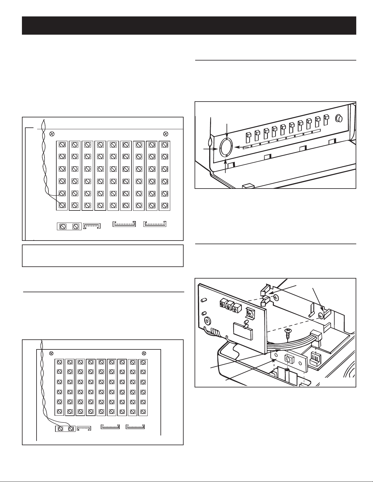
CONNECTING VOLUME CONTROL WIRING
4
Page 5
INSTALLATION (Continued)
Refer to Figure 4. If a NuTone Volume Control is installed in
the system, connect the control’s IW-2 wiring to the ORN and
ORN/WHT screw terminals at the master station.
NuTone speaker may be connected to each volume
control. Each volume control/speaker counts as a
remote station. Remember: The maximum remote
connections to the Master Station is 9. Adding the
optional IAA-440 expansion module will increase the
system remote capability to 15 stations.
Refer to the installation instructions packed with the speaker
ORN
ORN/WHT
Only ONE
PREPARING MASTER STATION PANEL FOR
OPTIONAL DOOR RELEASE PUSHBUTTON
To remove the pushbutton cover, position the master station
face up. Be careful not to damage the cables on the back of
the unit.
1. Refer to Figure 6. Open the left-hand door on the master
station panel.
FIGURE 6
2. Cut the 4 retainer webs from the pushbutton cover.
3. Remove cover. The door release pushbutton will be
installed and connected after the master panel has been
mounted to the rough-in frame.
FIGURE 4
NEVER USE 8 OHM STEREO SPEAKERS
WITH THIS SYSTEM!
volume control for wiring this unit.
CONNECTING DOOR SPEAKER WIRING
The Door Speakers connect to the Master Station Terminal
Board with twisted pair IW-2 wire.
Refer to Figure 5. Connect the two wires from the Door
1.
Speaker(s) to the 2 screw terminals marked
SPEAKER
on the master station terminal board.
DOOR
SPEAKER
DOOR
FIGURE 5
MOUNTING THE OPTIONAL CHIME
MODULE IN THE MASTER STATION PANEL
1. Position the master station panel face down on a soft cloth.
2. Refer to Figure 7. Align the optional NuTone IA-28 or
IA-29 chime module onto the mounting bracket located in
the master station.
SNAP IN PLACE
RED
WIRE
IA-29 ONLY
3. Apply firm, but even pressure to each side of the chime
module until it snaps into place.
4. Plug the 4 pin connector on the module into the connector
located on the master. When properly installed, the ribbon
cable will point away from the master station’s circuit
boards, as illustrated.
5. Connection from the pushbuttons to the master will be
made after the master panel has been mounted.
FIGURE 7
5
Page 6
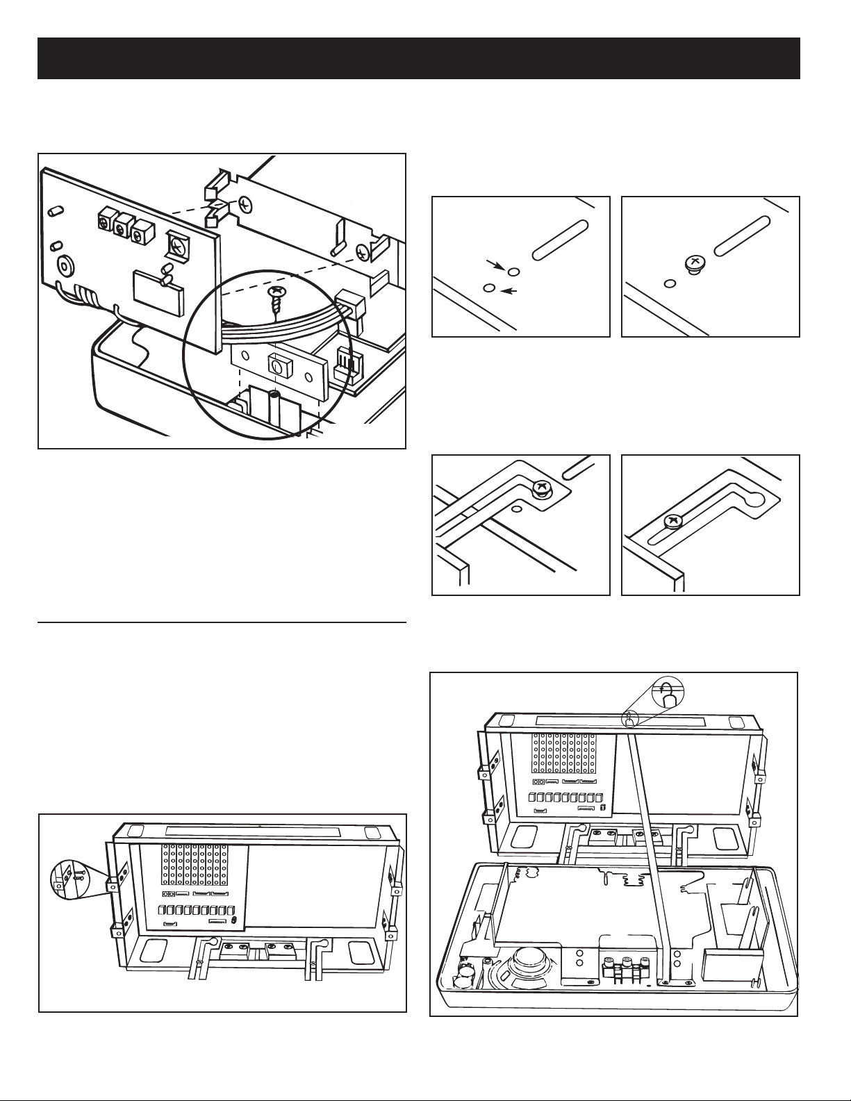
INSTALLATION (Continued)
Model IA-29 Only
1. Refer to Figure 8. Locate the chime selector switch
mounting bracket in the master unit.
FIGURE 8
2. Remove and set aside the chime selector switch retaining
screw located in the master unit.
3. Remove and discard the square foam pads on the chime
selector switch PC board connected to the chime module.
4. Slide the PC board into the mounting bracket on the
master station.
5. Fasten the chime selector switch PC board with the
retaining screw (earlier removed).
2. Refer to Figure 10A and 10B. For rough-in frames which
are recessed into the wall opening, insert two (2) shoulder
screws (provided) into the front two holes in the rough-in
frame. For rough-in frames which are mounted flush with
the wall, insert two (2) shoulder screws into the back two
holes in the rough-in frame.
BACK HOLE – FOR
FLUSH MOUNTED
ROUGH-INS
FRONT HOLE –
FOR RECESSED
ROUGH-IN
FIGURE 10A FIGURE 10B
3. Refer to Figure 11. Attach master panel to rough-in
frame by placing mounting hinge keyhole slots over
shoulder screw heads in the rough-in frame.
Refer to Figure 12. Slide master station panel to the right,
4.
then forward until it is flush with the wall surface.
5. Align master panel with rough-in frame.
FIGURE 11 FIGURE 12
MOUNTING THE MASTER STATION
NOTE: If an optional IAA-440 expansion module is to be
installed into the IMA-4406 master station, it should be
installed before mounting the master station. Refer the
installation instruction provided with the expansion module
before performing the following mounting steps.
1. Refer to Figure 9. Use two (2) #6x3⁄8˝ screws per bracket
to attach each of the four (4) mounting brackets to the
rough-in frame. Before tightening, slide the bracket so it is
flush with the wall surface (flush with rough-in frame if the
rough-in is installed after the wall board). Tighten all eight
(8) screws.
FIGURE 9
6. Refer to Figure 13. Attach support strap to rough-in
frame by attaching metal hook into hole in top of rough-in
frame. Using pliers, squeeze hook closed. Hook must not
come loose when master is later secured.
FIGURE 13
6
Page 7

INSTALLATION (Continued)
CONNECTING THE
POWER TRANSFORMERS
s
CAUTION
BE SURE THE AC POWER IS OFF BEFORE
CONNECTING THE POWER TRANSFORMERS. DO
NOT TURN AC POWER ON TO TRANSFORMERS
UNTIL ALL
STATIONS IS COMPLETE!
1. Refer to Figure 14. The transformers’ primary leads
should already be connected to the 120 volt AC house
supply wiring. Be sure power is off before connecting
THE POWER TRANSFORMER CONTAINS AN
INTERNAL FUSE.
DO NOT SHORT THE LOW VOLTAGE CONNECTING
SCREWS OF THE TRANSFORMER OR THE
TRANSFORMER WILL BE DESTROYED!
transformers to master unit.
2. Locate the two (2) sets of red/wht transformer leads on
the lower left corner of the master unit. Connect one pair
of low voltage leads to each transformer located in the
bottom of the rough-in.
WIRING AT THE REMOTE AND MASTER
IMPORTANT WARNING!
s
MOUNTING THE TRANSFORMER COVER
IMPORTANT: The transformer cover must be installed
for proper operation of the intercom.
1. Refer to Figure 15. Remove the left front and right rear
screws from the transformer enclosure. Set screws aside
for later installation.
2. Position the transformer cover (with insulator positioned
towards transformers) over the transformer enclosure so
holes in cover align with holes in enclosure.
3. Fasten cover with two (2) screws previously removed.
FIGURE 14
FIGURE 15
7
Page 8

INSTALLATION (Continued)
CONNECTING THE MASTER STATION TO
THE TERMINAL BOARD
1. Refer to Figures 16 and 17. Plug all five connectors into
the terminal board.
. • Insert black ribbon cable with 10 pin plug into CN104
1
connector.
1. • Insert multi-color ribbon cable with 14 pin plug into
CN102 connector.
1. • Insert multi-color ribbon cable with 9 pin plug into CN106
connector.
1. • Insert brown shielded cable with 12 pin plug into CN101
connector.
1. • Insert gray shielded cable with 11 pin plug into CN116
connector.
1. • No connection is made to connector CN111 unless
IAA-440 expansion module is used.
2. Make sure the alignment keys are properly aligned before
applying pressure to the connector.
3. After all connectors are plugged into the terminal board,
position the extra ribbon cable length toward the top of the
rough-in frame.
4. If an IAA-440 expansion module is included in this
installation, proceed with the connection of the module to
the expansion module terminal board at this time. Refer to
the installation instructions provided with the expansion
module.
FIGURE 16
MULTI-COLOR
RIBBON CABLE
WITH 9 PIN PLUG
BROWN CABLE
WITH 12 PIN
PLUG
BLACK RIBBON
CABLE WITH
10 PIN PLUG
MULTI-COLOR
RIBBON CABLE
WITH 14 PIN
PLUG
CN106
CN104
CN101
CN116
CN102
GRAY CABLE
WITH 11 PIN
PLUG
CN111
USED WITH
OPTIONAL IAA-440
EXPANSION
MODULE
FIGURE 17
8
Page 9

INSTALLATION (Continued)
CONNECTING THE RADIO ANTENNA
1. Refer to Figure 18. Plug radio antenna (supplied with
IR105 rough-in frame) into the 2-pin connector located on
the main circuit board. Be certain the tab on the connector
is facing towards the top of the master unit, as illustrated.
TAB
FIGURE 18
NOTE: Any excess antenna cable should be located
outside of Rough-in.
CONNECTING THE OPTIONAL
CHIME MODULE
It is now time to connect the optional chime module that you
earlier installed into the master station.
efer to Figure 20.Identify the front chime pushbutton
1.R
wires.
2. Connect the front pushbutton wires to the screw terminals
marked FRONT and COMMON on the chime module.
3. Repeat steps 1 and 2 for the
pushbuttons.
4. Refer to the instructions packed with the chime module
for information on chime volume level and chime tune
selection (IA-29 only).
FRONT
CHIME
VOLUME
REAR and SIDE chime
REAR
SIDE
COMMON
In most locations the antenna supplied with the rough-in
frame provides adequate AM reception; however, in rural or
weak signal areas, a separate AM antenna may be required.
Refer to the following instruction when selecting and
connecting an AM antenna.
1. Refer to Figure 19. Move the auxiliary antenna selector
switch to the AM position.
Connect 50 feet of 22 ga. insulated wire to the screw
2.
terminal marked
3. Run the wire from the master station location to the attic.
Fasten the insulated wire at one end of the attic; stretch
the wire to its full length and fasten at the opposite end.
Fasten the insulated wire at several locations between
ends to prevent sagging.
AM ONLY
AM ANTENNA.
AM/FM
AM ANTENNA
FIGURE 20
CONNECTING OPTIONAL
ELECTRONIC CHIME
1. Refer to Figure 21. Connect NuTone IW-2 cable from the
chime to the (+) and (-) screw terminals on the master
station’s main circuit board.
2. Refer to the instructions packed with the chime for
complete wiring information.
IMPORTANT: Failure to use NuTone IW-2 cable will
cause the system to hum at all times.
FIGURE 19
(–) (+)
ELECTRONIC
CHIME
FIGURE 21
9
Page 10

INSTALLATION (Continued)
CONNECTING OPTIONAL ACCESSORIES
1. Refer to Figure 22. To connect an external audio source
(NuTone Model CP-95 cassette, stereo system, VCR, TV,
etc. with low level audio output) to the IMA-4406 master
station, locate the TAPE and AUXiliary inputs on the
upper center of the master station’s main circuit board.
2. Connect an RCA™phono type plug to the shielded audio
cable coming from the external audio source. Follow the
phono plug manufacturer’s instructions when connecting
to the cable.
3. Insert the phono plug into the appropriate input jack
(TAPE or AUX) on the master station’s main circuit board.
NOTE: The TAPE and AUX inputs have input audio level
controls to allow matching of the external audio source
with the radio and CD audio of the master.
4. To use the selected source audio for recording onto a
cassette recorder, insert the recorder’s plug into the
master station’s LINE OUT jack.
5. Optional connection to provide program audio only:
• The CD, radio or optional audio sources can be
channeled through an auxiliary amplifier (purchase
a NuTone Model IMA-516 separately) to provide
uninterrupted music (no intercom) to separate
speakers. This type of installation can be used for
example, in a doctor’s office where intercom and
music are desired in the office area, but music only
is desired in the waiting room.
NOTE: If an auxiliary amplifier is used, connect the
•
master station’s LINE OUT jacks to the auxiliary
amplifier’s low-level audio input wires using shielded
audio cable (not supplied by NuTone).
• NOTE: When using the LINE OUT for recording
program audio or distributing program audio only
through an external amplifier, the automatic CD PAUSE
should be disabled or the audio present on the LINE
OUT jack will stop when the intercom or chime is used.
To disable the
manual.
CD PAUSE, refer to the homeowner’s
CONNECTING POWER TO THE OPTIONAL
CP-95 CASSETTE PLAYER
1. Refer to Figure 23. Cut the protective sleeving from the end
of the BLK/WHT CP-95 power supply leads.
2. Separate 2 inches of the supply leads.
. Strip the outer insulation back approximately 5/8˝ from the
3
end of the cable.
4. Connect the power leads from the CP-95 to the CP-95 power
supply leads of the master station (polarity is not important).
Use wire nuts to protect the bare wires from shorting.
CONNECT CP-95
POWER LEADS
FIGURE 23
s
IMPORTANT
Be sure the power to the transformers in the IR-105 rough-in
is OFF before connecting the CP-95 power supply leads!!
s
LINE OUT
AUX INPUT
TAPE INPUT
FIGURE 22
10
Page 11

INSTALLATION (Continued)
MOUNTING AND CONNECTING
OPTIONAL DOOR RELEASE PUSHBUTTON
You have previously prepared the master station for the
optional release pushbutton.
efer to Figure 24. Feed one wire from the door release
1.R
transformer and one wire from the door release mechanism
through the pushbutton hole in the master station panel.
FIGURE 24
2. Connect the two (2) wires to the PB1WHCL pushbutton.
3. Rotate the pushbutton so the screws are on the top and
bottom as illustrated, then snap the button into the
mounting hole.
clearance hole must be drilled behind the mounting bracket
before securing the master station panel.
POWERING UP THE SYSTEM
Once all connections have been completed throughout the
system, it is time to apply power to the master station.
s
CAUTION
WHEN RAISING THE MASTER PANEL TO ITS FINAL
POSITION, DO IT SLOWLY! BE CAREFUL NOT TO HIT OR
DAMAGE ANY OF THE CIRCUIT BOARDS OR CABLES.
s
CONNECTING THE MEMORY
BACK UP BATTERY
Refer to Figure 25. Connect the 2-pin plug from the battery
to the connector located on the control circuit board.
SECURING THE MASTER PANEL
2 PIN PLUG
1. Refer to Figure 26. Inspect all wiring connections to make
sure they are complete and correct.
2. Make sure all antenna connections are secure.
3. Dress all remote station wires flat against the terminal
board.
Position the master station panel over the rough-in frame
4.
and align screw holes in master with mounting brackets.
Two (2) mounting holes are located behind the CD
Player door.
5. Secure the master station panel to the rough-in mounting
brackets with four (4) screws (provided).
NOTE:The mounting screws will pierce the wall surface
behind the mounting brackets. If the wall surface is hard, a
PLEASE NOTE
If permanent AC power has not been connected, or the
AC power will be off for long periods of time, the
battery should not be connected at this time. When the
battery is connected, the correct time and programmed
radio memory stations will be retained for
approximately 30 hours on battery backup.
2 PIN
CONNECTOR
FIGURE 25
FIGURE 26
Apply power to the master station by turning on the circuit
1.
breaker that supplies power to the transformers in the
IR-105 rough-in frame.
2. When power is first applied, the LCD display will flash
1:00 PM. Refer to the Operational Checkout section of
this manual for additional information.
11
Page 12

OPERATIONAL CHECKOUT
SYSTEM OPERATING CONTROLS
SCAN: Activates scan tuning during AM/FM operation.
1
st UP/DOWN TUNING: Provides manual tuning of the AM/FM radio.
2
MEMORY 1-6 KEYS: Provides direct access to stored radio
3
frequencies.
4
TRACK : Returns to the beginning of the current track and/or previous
tracks.
5
TRACK : Advances the CD Player to the beginning of the next track.
6
RDM/RPT: (Random/Repeat) Set the CD play mode to: REPEAT ONE,
REPEAT ALL or RANDOM PLAY.
PLAY/PAUSE: Activates the operation of the CD Player. Pressing the
7
key during play operation will pause the CD Player.
8
SEARCH : Quickly searches the track in the forward direction.
9
SEARCH : Quickly searches the track in the reverse direction.
0
1
CD PLAYER DOOR: Open CD door and snap CD disc onto spindle.
11
TIME SET: Used with the stkeys to set the clock and timer.
12
MEMORY SET: Stores desired radio frequencies into a selected
memory location.
13
CLOSE: Press here to close CD Player door.
14
TREBLE: Adjusts the high frequency audio content of the source audio.
15
STOP: Ends the CD Play mode and turns off the program audio.
16
BASS: Adjusts the low frequency audio content of the source audio.
17
SYSTEM VOLUME: Adjusts the program audio level throughout the
system.
18
OPEN: Causes the CD Player door to open.
LOUDNESS: Compensates for the bass and treble response the human
19
ear has when listening to audio at low volume levels.
20
MICROPROCESSOR RESET: Initiates a reset of the microprocessor.
NOTE: A reset of the microprocessor will erase the system’s memory.
s
s
s
s
21
DISPLAY: Sets the LCD display mode: CLOCK, RADIO FREQUENCY,
TRACK NUMBER or TIME PLAYED.
22
INTERCOM VOLUME: Adjusts intercom audio level throughout the
system.
23
MASTER STATION STATUS SWITCHES: Sets the master station in
one of the following modes: RADIO/INTERCOM, INTERCOM ONLY,
OFF or MONITOR.
24
REMOTE STATION STATUS SWITCHES: Sets the remote stations in
one of the following modes: RADIO/INTERCOM, INTERCOM ONLY,
OFF or MONITOR. Note: If the optional expansion module is installed, 6
additional switches will be located on the right side of the master.
25
DOOR RELEASE KNOCKOUT: Mounting hole for optional door
release pushbutton.
END CALL: Ends intercom communication and returns system to audio
26
ource.
s
27
DOOR TALK: Initiates intercom communication to the door speakers.
28
INSIDE/PATIO: Initiates intercom communication to remote stations.
29
TIMER: Enables or disables the radio timer. The indicator light will
illuminate next to the Timer key when the Radio Timer is activated.
PROGRAM AUDIO SOURCE: Selects the program audio source: AM,
30
FM, TAPE and AUX. The indicator light will illuminate next to the
selected program audio source.
ELECTRONIC CHIME TUNE SELECTION: Selects the tune of the
31
optional NuTone IA-29 Chime Module.
32
PROGRAM OFF: Turns off the selected program audio source. The
program Off key does not affect the intercom or chime operation.
33
MASTER VOLUME: Adjusts the volume at the master station.
33
32
31
3
2
2
27
26
2
1
0
9
8
5
4
2
3
2
23
22
6
5
4
20
1
2
8 9
7
3
1
7
161
18
9
1
15
2
0
1
1
14
11
12
Page 13

SET TIME
PM
1:00
OPERATIONAL CHECKOUT (Continued)
DIGITAL CLOCK
SETTING THE TIME
The proper clock setting procedure is arranged in 4
segments. Each segment must be completed in 5 seconds.
Follow the procedure below.
1. Press the TIME SET key one time.
The ‘Hours’ display will begin
flashing, and the words ‘Set Time’
will display.
2. Within 5 seconds, press the
Hour and AM/PM are displayed.
3. Within the next 5 seconds, press the TIME SET key
again. The ‘Minutes’ display will begin flashing.
4. Again, within 5 seconds, press the
correct minute is displayed.
5. Release the keys after entering the correct time. The
display will stop flashing in 5 seconds, and the time will
be set.
NOTE: Pressing the s or t keys momentarily will cause the
time to advance or reverse one digit. Pressing the s ort
keys continuously for more than 1⁄2 second will cause the
digits to advance or reverse at high speed.
s or t key until the correct
s and t keys until the
SYSTEM CHECKOUT
Set the following control settings and perform the indicated
tests.
1. Set all STATION STATUS SWITCHES to the RADIO
INTERCOM position.
2. Set the MASTER VOLUME control to 2⁄3 position.
3. Set each remote station VOLUME control to 2⁄3 position.
4. Set the SYSTEM VOLUME control to 1⁄3 position.
5. Set the INTERCOM VOLUME control to 2⁄3 position.
6. Set the BASS and TREBLE control to 1⁄2 position.
7. Press the OPEN key on the master station. The CD
Player door will open. Complete opening the door by
moving the CD door from left to right.
8. Snap a CD disc onto the spindle of the CD player.
s
CAUTION
Never touch the lens of the CD player or damage
will result!
9. Close the CD player door by moving the door from right to
left until the door latches closed.
10. Tune in a strong local FM radio station as follows:
• Press the FM key.
• Locate a strong FM radio signal by using the
Beginning with the master station, check each station in the
system for proper operation using the following procedure.
Press the
1.
audio will mute.
2. Release the
INSIDE/PATIO key to initiate a call. Radio
INSIDE/PATIO key to hear the reply.
s
stkeys.
3. Press the
end and radio audio will return to all stations in the system.
4. Press the
audio from the initiating station will be heard at the door
speaker(s) and all stations in the system.
5. Release the
peaker(s) will be heard at all stations in the system.
s
6. Press the
end and radio audio will return to all stations in the
system.
7. Press and hold the END CALL key for 2 seconds at any
remote station. The radio will turn off.
8. Press and hold the END CALL key for 2 seconds at any
remote station. The radio will turn on. For additional
information on remote radio control, refer to the
homeowner’s manual.
9. With a CD in the CD player, press and hold the
CALL key at any remote station until a BEEP BEEP is
heard at the remote station. In a few moments, the CD
will begin playing.
10. Press and hold the
remote station. The CD player and audio will stop. For
additional information on remote CD Player control, refer
to the homeowner’s manual.
11. Repeat procedure at all remote stations.
END CALL key. Intercom communication will
DOOR TALK key. Radio audio will mute and
DOOR TALK key. Audio from the door
END CALL key. Door communications will
END
END CALL key for 2 seconds at any
SETTING PROGRAM AUDIO CONTROLS
The volume levels required at each station may vary with the
location of the speaker and the size of the room where the
speaker is located. Spend some time experimenting with the
volume levels, and adjust each speaker so that you can
clearly hear the radio, CD and intercom. Use the following
procedures to set your system’s volume levels.
1. At each remote station, turn the VOLUME control
completely clockwise to maximum volume.
At the master station, set the
2.
SPEAKER STATUS SWITCHES to the RADIO
INTERCOM
Turn the MASTER VOLUME control to maximum volume.
3.
Turn the
4.
to approximately 1⁄3 volume.
5. Select an AM or FM radio station with a strong, clear signal.
6. Adjust the master station’s SYSTEM VOLUME control
until you have ample volume at the remote station that
requires the highest volume (i.e. a large living room, family
room, basement, etc.)
PLEASE NOTE: The master station and all remote stations
(except door speakers) are equipped with volume controls.
Although the master station SYSTEM VOLUME sets the
system’s volume level, you may adjust an individual
speaker’s volume level as desired.
position.
SYSTEM VOLUME control on the master station
REMOTE and MASTER
13
Page 14

OPERATIONAL CHECKOUT (Continued)
SETTING PROGRAM AUDIO CONTROLS
(CONTINUED)
7. Adjust the MASTER VOLUME control and all remote
station’s volume controls to the volume level you desire.
In order to have proper intercom audio levels, it is
ecommended that the MASTER VOLUMEand remote
r
stations’
VOLUME controls be set at 2⁄3 volume or higher.
SETTING INTERCOM VOLUME
1. Initiate an intercom call from the master by pressing the
INSIDE/PATIO key.
2. Speak with a clear normal voice about 2-3 feet from the
master station’s speaker.
3. Adjust the
station’s audio is clearly heard at all stations in the
system.
PLEASE NOTE: The volume control at all stations should be
set between 1⁄2 to maximum volume for proper intercom
operation.
4. Repeat the above procedure at several remote station
locations until an acceptable intercom audio level is
achieved at all stations.
INTERCOM VOLUME control until the initiating
SETTING INTERNAL INTERCOM VOLUME
CONTROL
The internal intercom volume control has been factory set for
optimum intercom operation. Should the intercom gain need
to be adjusted beyond the range of the Intercom Volume
Control behind the left front door, use the following procedure:
1. Refer to Figure 27. Using a thin-blade screwdriver, adjust
the internal control counter-clockwise as viewed from the
rear of the master station panel. This adjustment will
reduce the intercom gain.
2. To increase the intercom gain, turn the internal control
clockwise.
ROUGH-IN
SETTING THE BEEP TONE LEVEL
The internal BEEP tone volume control has been factory set
to a normal level for the BEEP tone to be heard when the CD
Player operation is initiated from a remote station by using
the AM/FM/CD CONTROL/END CALL key. Should that level
require adjustment, use the following procedure:
1. Refer to Figure 28. Using a thin-blade screwdriver, adjust
the BEEP TONE volume control counter-clockwise as
viewed from the rear of the master station panel to reduce
the BEEP level.
2. To increase the BEEP level, turn the control clockwise.
BEEP TONE
FIGURE 28
SETTING THE EXTERNAL AUDIO
SOURCE LEVEL
The TAPE and AUX level controls have been factory set at
maximum. These controls can be adjusted to match the
external audio source level with the built-in radio and CD
Player levels. Use the following procedure:
1. Press the FM key.
2. Tune the radio to a strong local radio station.
3. Turn on the external audio source(s) connected to the
master station.
4. Switch the master station from FM to TAPE or AUX.
5.
Refer to Figure 29. Using a thin-blade screwdriver, adjust
TAPE/AUX control to match the audio level of the
the
external audio source with the FM radio.
BOTTOM OF
MASTER
AUX TAPE
LEVEL LEVEL
FIGURE 27
FIGURE 29
14
Page 15

OPERATIONAL CHECKOUT (Continued)
DIAGNOSTIC TESTS
The following diagnostic tests have been incorporated into
the NuTone IMA-4406 master station to assist in system
troubleshooting.
• Master station keyboard test
• Remote station control voltage test
• Display test
The following applies to all diagnostic tests:
1. To access any of the diagnostic tests, the system must be
PROGRAM OFF mode.
in the
2.
Pressing the MEMORY SET key will end the current
diagnostic test.
3. The current diagnostic test will end after one minute of
inactivity.
PLEASE NOTE: An incorrect voltage caused
by miswiring, shorted wiring or a defective
remote station may cause the radio and/or CD
Player to turn off/on, thus preventing the unit
from entering the diagnostic mode. Should this
occur, the master station’s control timer will stop
the on/off cycling after 30 seconds.
Remote Station Keyboard Test – Verifies that all keys on
the master station are functioning properly. To activate: Press
and hold the following key in this order:
1. s key 3. Memory 1 key
t key 4. Release all keys
2.
In this mode, the hours in the display represents the current
diagnostic test and the minutes indicate the current key being
pressed. The following will be displayed as the key is
pressed.
KEY DISPLAY KEY DISPLAY
No key 1:00 Memory 2 1:14
Scan 1:01 Memory 3 1:15
s 1:02 Memory 4 1:16
t 1:03 Memory 5 1:17
Program Off
AM 1:05 Play/Pause 1:19
FM
Tape 1:07 Track 1:21
Aux 1:08 Track 1:22
Timer
Inside/Patio 1:10 Stop 1:24
Door Talk 1:11 Time Set 1:25
End Call 1:12 Memory Set 1:26
Memory 1
1:04
1:06
1:09
1:13
Memory 6
RDM/RPT
s
s
Display 1:23
1:18
1:20
Remote Station Control Voltage Test – Displays the
voltage at the master’s microprocessor control line. To
activate, press and hold
1. s key 3. Memory 2 key
t key 4. Release all keys
2.
xample:
E
Display Voltage at Microprocessor
2:3.0 3.0 volts
2:1.9 1.9 volts
2:0.1 .1 volts
In this mode, the hours represent the diagnostic test, and the
minutes indicate the voltage at the master station’s
microprocessor.
Mode Maximum Minimum
End Call
Inside/Patio 2.4 volts 1.6 volts
Door Talk 3.6 volts 2.8 volts
Quiescent 5.0 volts 4.3 volts
The control voltage windows for the three intercom modes
and quiescent mode are listed above. For proper intercom
operation, the control voltage produced when an intercom
key is pressed at a remote station should fall between the
voltage indicated.
NOTE: Pressing the END CALL, DOOR TALK, or
INSIDE/PATIO keys at the master station will not change the
voltage on the control line. If a remote station does not
produce a voltage within the above window for a specific
intercom function, check the following:
• Make sure all connections from the master station are
properly installed at the terminal board.
• Check IW-6 connections at the master station terminal
board and at each remote station.
• Confirm that the suspect remote station functions properly
by replacing it with a known good remote station.
Display Test – Displays all segments in the LCD display. To
activate, press and hold
1. s key 3. Memory 3 key
2. t key 4. Release all keys
the following keys:
Voltage Window
.4 volts 0 volts
the following in this order:
RESETTING THE MICROPROCESSOR
NOTE: Resetting the microprocessor will cause the radio
memory channels and clock time to be lost.
Should the system not operate properly, the internal
microprocessor may require resetting. To reset the
microprocessor, use the point of a pen to press the reset
button through the access hole behind the right lower door.
See “System Operating Control” section.
15
Page 16

INSTALLER’S TROUBLESHOOTING GUIDE
TROUBLE
No radio, no intercom.
No Display).
(
o radio, intercom working.
N
(AM/FM indicator on.)
Low or distorted radio
volume.
Weak and distorted music,
chime and intercom audio.
POSSIBLE CAUSE POSSIBLE REMEDY
No electrical power.
Defective transformer.
aulty Master Station.
F
nstallation problem.
I
Antenna problem.
Incorrect volume setting.
Shorted or mis connected remote
speaker wiring.
Be certain 120VAC, 60Hz power has been provided to the primaries
f both 801T Transformers. No less than 16VAC should be
o
measured on the secondary of either Transformer.
Replace transformer.
solate Master Station from installation by removing ribbon cables
I
from terminal board and wait one minute for timeout. With power on,
radio should be playing at Master. If no radio, Master is probably
aulty. If radio plays, reconnect ribbon cables.
f
heck terminal board for shorted terminals or miswired cables.
C
Remove one 6-wire cable at a time to locate faulty line. When radio
comes on, check speaker connections and run continuity check of
speaker wiring.
Check for shorted antenna connection. Remove antenna connector
from tuner board and touch each pin with metallic object. If radio
plays, antenna is not functioning; be sure it is installed properly. In
weak signal areas, an outside antenna may be necessary. Also see
“Connecting the Radio Antenna”
Follow “Setting Program Audio Controls” instructions under
OPERATIONAL CHECKOUT.
This unit contains a protection device which opens if the audio
amplifier detects an overload condition. If the music, chime and
intercom audio becomes weak and distorted, remove power from the
master station for 10 minutes; this will reset the protective device. If
the audio returns to normal, the remote speaker wiring and remote
speakers should be checked for bare, shorted and/or mis-connected
wires. The problem must be found and corrected before the master
station will properly function.
Low or no intercom volume
from remote speaker in
MONITOR mode.
Improper operation.
Program and Intercom Volume
Control adjustment.
Be sure remote speaker set for MONITOR has its volume control set
between
set between
instructions in OPERATIONAL CHECKOUT.
Follow these instructions whenever the radio tends to overpower
transmissions from a remote speaker in the MONITOR mode. These
instructions will help you get the proper balance between the radio
and the monitored speaker.
1. Set system volume control to midpoint.
2. Set master to CD/TAPE or AUX position.
3. Adjust volume control for each remote station and speaker in
4. Set master to AM or FM and tune to a strong AM or FM station.
5. Adjust program volume control for a desired listening level.
6. Increase Intercom volume control setting. Adjust clockwise to
1
⁄2 and max, and receiving speakers have volume controls
1
⁄2 and max. Follow “Setting Intercom Volume”
3
master station
desired monitor volume.
⁄4 position.
-Continued-
16
Page 17

INSTALLER’S TROUBLESHOOTING GUIDE
TROUBLE
System squeals when using
ntercom.
i
Hum in speakers.
Static. Loose ground connection.
POSSIBLE CAUSE POSSIBLE REMEDY
Shorted wire on master or
emote terminal board.
r
Two or more Remote Stations on
same wire run to Master.
peakers in adjacent rooms
S
mounted on common wall, or
mounted back to back.
Improper wire used in
installation.
Intercom wiring run too close to
household AC power wiring.
Shorted intercom power wiring or
power wiring shorted to ground.
Interference from household
electrical fixtures.
Check for short between terminals or loose wire.
Make separate cable (IW-6) runs from each Remote Station to the
Master.
f speakers are mounted directly back to back, one speaker will have
I
to be relocated. If speakers are in a common wall, try placing
fiberglass insulation behind each speaker, or isolate the speakers
rom the wall by placing rubber washers or weather stripping between
f
speaker and wall.
NuTone Model IW-6 6-conductor twisted pair cable must be used.
Keep intercom wiring as far as practical from household AC power
wiring. Do not run intercom wiring parallel to AC power wiring.
Check power connections to Master and connections to transformers.
A dimmer may cause interference. For dimmer and fluorescent
lighting interference, use filters (G.E. 89G635 or equivalent;
NuTone Part No. 1559A-000).
Check ground connection to Master and connection to earth ground
source.
Remote Station not working.
No door communication.
Optional Electronic Chime
(Models IA-28 or IA-29) does
not operate or operates at a
low level.
Electronic chime can't be
heard through the master
station or remote speakers.
Interference from household
electrical fixtures.
Interference from household
electrical appliances.
Wire installation.
Speaker.
Wire installation.
Speaker.
Wire installation.
Improper volume setting.
Improper volume setting.
Improper volume setting.
A dimmer may cause interference. For dimmer and fluorescent
lighting interference, use filters (G.E. 89G635 or equivalent;
NuTone Part No. 1559A-000).
Correct interference at the source: fish tank, heater, hand tool, coffee
pot, etc.
Check terminal board for broken wire or loose connection. Check
continuity of wire.
Check continuity of speaker. Clean switch controls. Substitute with
speaker known to be in working order.
Check continuity of wiring. Check connections at speaker and Master.
Check with a speaker known to be in working order.
Be certain the chime is properly connected to the master station. Also,
be certain the front, side and rear buttons are properly connected to
the chime board.
Adjust the volume of the chime module by turning the volume
potentiometer located on the chime module. NOTE: Chime Audio will
NOT be heard at stations selected to the OFF or MONITOR.
Be certain the electronic chime is properly connected to the master
station's electronic chime input screw terminals.
Adjust the volume of the electronic chime by turning volume
potentiometer located on the chime.
17
-Continued-
Page 18

INSTALLER’S TROUBLESHOOTING GUIDE
TROUBLE POSSIBLE CAUSE POSSIBLE REMEDY
Cannot receive radio station
hich is received by another
w
radio in home.
IU is displayed continuously,
nd the radio cycles on/off
a
continuously.
Low intercom volume. Intercom volume control
Faulty antenna connection. Antenna should be located in attic and connected to tuner in Master.
heck antenna connector to be sure it is connected to 2 pin
C
connector on master.
Shorted IW-6 wire going to
emote station. Defective remote
r
station.
djustment.
a
Set remote station status switches one at a time to the OFF position.
f IU stops at certain station, that stations wire or remote station is
I
defective.
Increase intercom volume setting.
When CD playback is started,
it stops immediately or stops
during playback.
With certain discs a loud pop
is produced or play stops.
Volume controls on remote
stations set below
Internal intercom volume control. Increase setting of internal intercom gain control.
Disc is badly scratched or
warped.
inward.
Disc is dirty.
Disc has bad scratch or is
warped.
Disc is extremely dirty. Clean disc if there are fingerprints or dirt on the disc. Wipe off with a
1
⁄2.
Keep remote stations volume controls at 1⁄2 or higher for proper
intercom operation.
Replace the disc.
Install CD with label facing outward.Disc is loaded with label facing
Replace with conventional music format CD.Improper data format (CD ROM)
Clean disc if there are fingerprints or dirt on the disc. Wipe off with a
soft cotton cloth. Wipe the disc from the center to the outside edge.
Never use paint thinner, Benzene
Replace the disc.
soft cotton cloth. Wipe the disc from the center to the outside edge.
Never use paint thinner, Benzene
™
or conventional record cleaners.
™
or conventional record cleaners.
18
Page 19

19
Page 20

4820 Red Bank Road, Cincinnati, Ohio 45227
Printed in China, Rev. 06/06, Part No. 62377Product specifications subject to change without notice.
 Loading...