

Page 1
To register this product,
visit: www.nutone.com
MODELS ICUDWH • ICUNUW
BUILT-IN IRONING CENTER
READ AND SAVE THESE INSTRUCTIONS
WARNING
1. Do not place EXCESSIVE WEIGHT (weight should not exceed 30
pounds) on the ironing board when opened as it is designed to accept
normal ironing use only.
2. Do not use ironing board surface as a shelf or as a child diaper-changing
surface.
3. To avoid getting pinched or otherwise injured, keep fingers/hands clear
of moving parts.
4. Allow iron to cool down before storing in the cabinet.
5. Empty water reservoir and turn off steam action prior to storing iron.
6. Unplug iron cord from outlet when storing, and use care to avoid pinching the electrical cord.
7. Keep ironing board stored and door closed when not in use.
8. Do not allow children to play with, on, or around the Ironing Center.
TOOLS NEEDED
• Tape measure
• Phillips screwdriver
• Drill with 3/32” dia. bit
• Stud finder
INSTALLATION
• Drywall saw or utility knife
• Level
• Pencil
Page 1
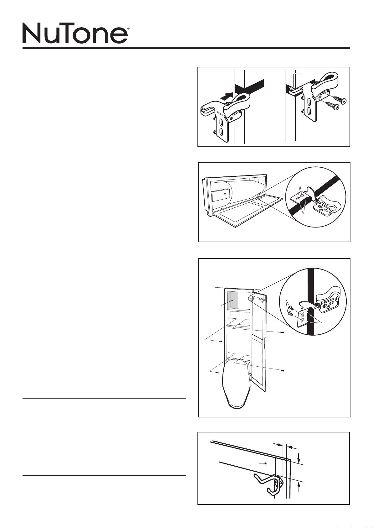
3. Cut the hole in the wall. (Fig. 2)
Locate the wall studs using a stud finder. Cut a 14-1/4”
x 46-1/4” opening in the wall between two studs using a
drywall saw or utility knife.
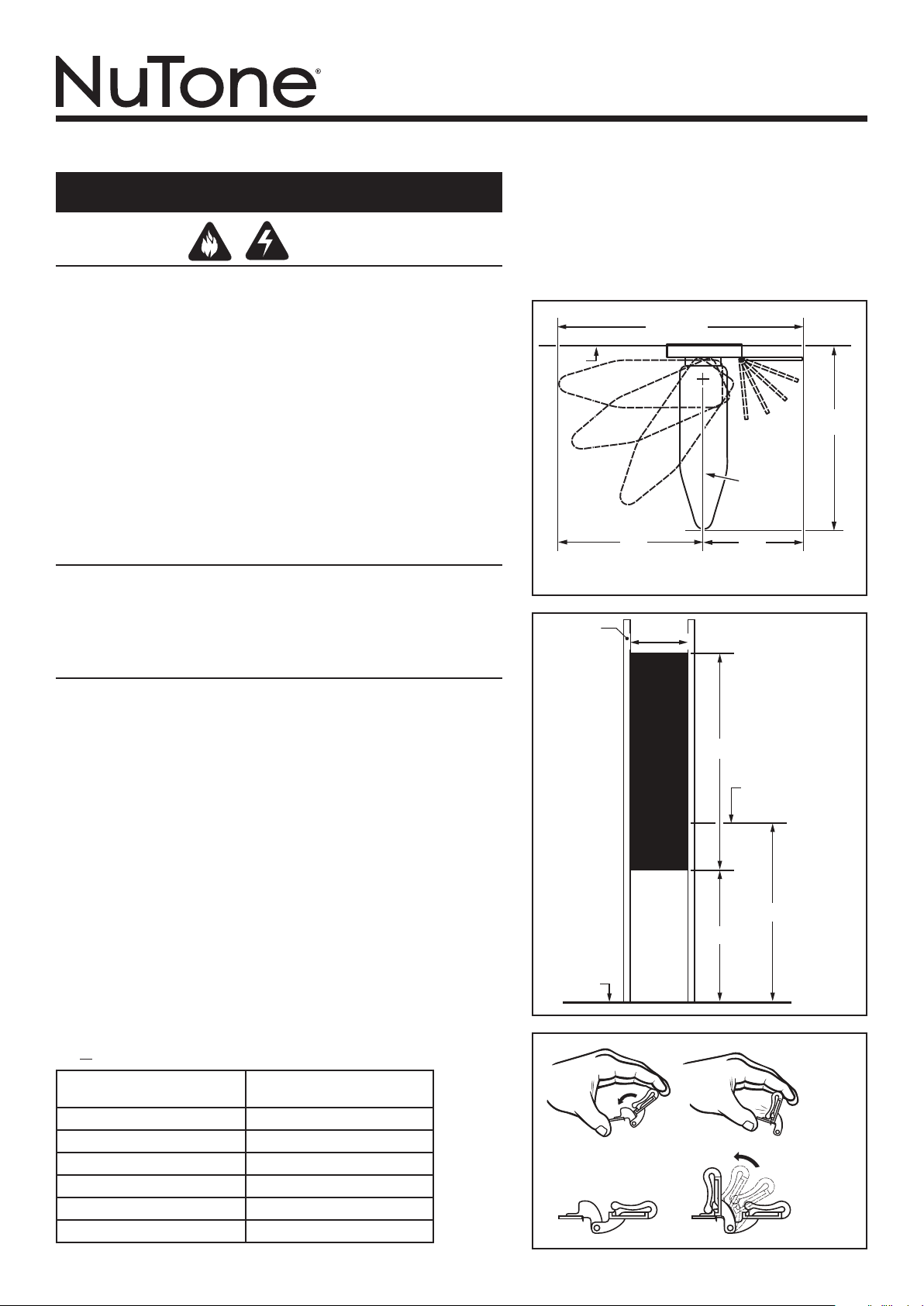
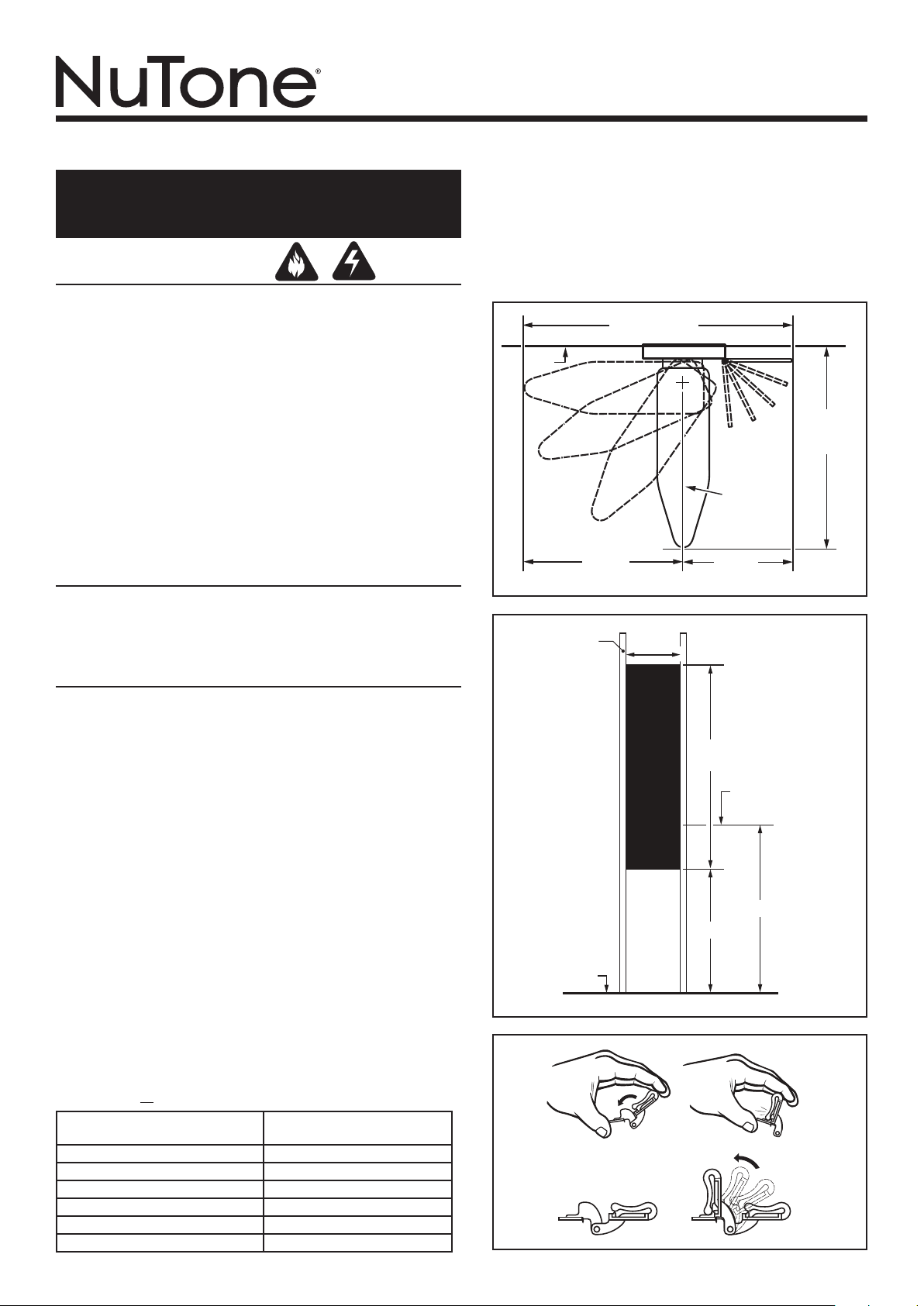
4. Close hinges. (Fig. 3)
Close the hinges so that they snap shut.
55"
Clearance
Wall
44"
Clearance
TOP VIEW
Ironing
Board
Center Line
34"
21"
Fig. 1
16"
on-center
studs
14-1/4"
1. Determine where to install. (Fig 1)
The NuTone Ironing Centers are designed to fit between standard 16” oncenter wall studs. A 46-1/4 ” x 14-1/4 ”x 4” deep opening is required. 24”
on-center studs will require framing to proper opening size.
When selecting the exact location for your cabinet, remember to leave room
for your door to open. The door can be mounted on either side of the cabinet.
It is recommended that you allow at least 55 inches wide and 44 inches
deep clearance around the ironing board. The ironing board will swivel to
either side so you will not need to be concerned about blocking a walkway.
However, if rotating the ironing board 900 in both directions, allow a total
width clearance of at least 68 inches.
CAUTION: Make sure the location you choose is free of all electrical and
mechanical services. Also make sure that you have an electrical outlet nearby,
or have purchased the Deluxe Accessory (Model No. ICAK) for installation
into the Ironing Center cabinet.
2. Determine distance above floor. (Fig. 2)
The ironing center is designed to be easily installed between two 16”-oncenter wall studs. First determine the desired height of the ironing board
from the floor (Dimension a). Standard countertop height is 36”. Use the
chart below to find and mark the bottom of the wall opening (Dimension
b) - or - use the included template.
Desired Ironing Board Height a
(Above Floor)
33 inches 22-3/4 inches
34 inches 23-3/4 inches
35 inches 24-3/4 inches
36 inches 25-3/4 inches
37 inches 26-3/4 inches
38 inches 27-3/4 inches
Height to Bottom of Opening b
(Above Floor)
Floor
Wall
Opening
46-1/4"
Top of
ironing
board
a
b
Fig. 2
Fig. 3
Page 2
MODELS ICUDWH • ICUNUW
5/8"
5. Attach hinges to door. (Fig. 4)
The hinges can be used to mount the door on the right or left side of
the cabinet. The hinges mount to the door the same way, regardless
of the side they’re mounted on.
Slide the lower section of the hinge into the door notch. When the
hinge is properly seated in place, the edge of the pivot pin will be
flush with the edge of the door. Mark the two hinge mounting hole
locations (the two slots) in the center of each slot. Remove hinge and
drill a 3/32” pilot hole, 1/2” deep at each of the two (2) marked locations, being careful not to drill through the door. Reinstall the hinge
and secure it to the door using two (2) of the hinge mounting screws.
Note: The 3rd hole (the round hole) on the door side of the hinge can
be used if desired, but it is not necessary. Follow the same steps to
attach the second hinge.
6. Mark and drill pilot holes in cabinet frame for
door hinges (Fig . 5)
The door may be attached to either side of the cabinet.
Extend both door hinges fully open. Slide the door toward the cabinet
so that the hinges extend inside. Notice that each hinge has two small
“stop guides”. The stop guides should rest against the front edge of
the cabinet and stop the hinge from going further. Make sure the door
is centered on the cabinet - top to bottom.
Mark the center of the slots using a pencil or center punch. Move
the door aside.
7. Install cabinet into wall opening. (Fig. 6)
Place the cabinet in the wall opening.
Make sure the cabinet is level and plumb. Secure the cabinet to the
wall studs with the four (4) 1-5/8” mounting screws. It is recommended
to drill four (4) 1/8” dia. pilot holes through the sides of the cabinet to
avoid splintering. Do not drill into the wall studs or framing.
Remove blue protective film from iron shield in upper left corner.
If the ironing board does not move up and down freely, you may use
a dry bar of soap to lubricate the track in which the metal bar slides.
This may be repeated as needed.
If the swivel action of the ironing board needs to be tightened or
loosened, adjust the swivel nut located under the board.
8. Attach door to cabinet. (Fig. 6)
Drill 3/32” pilot holes, 1/2” deep at each of the four (4) locations
marked in Step 6. (2 for each hinge). Attach the door to the cabinet
using hinge mounting screws. Some adjustment may be necessary
to center the door on the cabinet.
9. Install garment hook. (Fig. 7)
Install the garment hook using the two (2) mounting screws supplied.
The placement of the garment hook should be 2” from the top edge
and 5/8” from the side edge of the door. It is recommended to drill
two (2) 1/16” dia. pilot holes part way in door to avoid splintering.
CAUTION: Do not drill all the way through the door.
Level
Iron Shield
(Remove
protective
film.)
Hinge
Mounting
Screws (4)
Mounting
Screws (4)
Pivot pin
Cabinet Frame
Mark center
of these slots
Stop guides
Cabinet
Frame
Page 2
Fig. 4
Fig. 5
Door
Stop
Guides
Door
MAINTENANCE
If the ironing board does not move up and down freely, you may use
a dry bar of soap to lubricate the track in which the metal bar slides.
This may be repeated as needed.
If the swivel action of the ironing board needs to be tightened or
loosened, adjust the swivel nut located under the board.
The ironing board is fitted with a heat-resistant cover. To avoid damage
to the cover: DO NOT WASH THE COVER.
The laminated surface of the ironing center may be wiped clean with
non-abrasive household cleaner.
SERVICE PARTS
97020252 Hardware Kit - Screws, Hinges, Garment Hook (ICUDWH)
97020253 Hardware Kit - Screws, Hinges, Garment Hook (ICUNUW)
97020742 Model ICAB, Ironing Board Cover
97020743 White, Raised Panel Door (ICUDWH)
Fig. 6
Door
2"
Fig. 7
Page 3
Pour enregistrer ce produit,
visitez : www.nutone.com
MODÈLES ICUDWH • ICUNUW
CENTRE DE REPASSAGE INTÉGRÉ
LISEZ CES DIRECTIVES ET
CONSERVEZ-LES
AVERTISSEMENT
1. Ne placez pas un POIDS EXCESSIF (ne pas dépasser 13,6 kg/30 livres)
sur la planche à repasser lorsqu’elle est ouverte car elle est conçue
uniquement pour accepter le poids d’un repassage normal.
2. N’utilisez pas la surface de la planche à repasser comme une tablette
ou comme une table à langer pour un enfant.
3. Pour éviter de vous pincer ou blesser, gardez les doigts et les mains à
l’écart des pièces mobiles.
4. Laissez le fer à repasser refroidir avant de le ranger dans l’armoire.
5. Videz le réservoir d’eau et arrêtez la fonction vapeur avant de ranger le
fer.
6. Débranchez le cordon électrique de la prise de courant avant de ranger
le fer et prenez garde de ne pas pincer le fil.
7. Gardez la planche à repasser dans l’armoire, la porte fermée, entre les
utilisations.
8. Ne laissez pas les enfants jouer avec le centre de repassage, ni sur la
planche, ni autour.
OUTILS REQUIS
• Ruban à mesurer
• Tournevis cruciforme
• Perceuse et mèche de
2,38 mm (3/32 po) de dia.
INSTALLATION
1. Déterminez le lieu d’installation. (Fig. 1)
Les centres de repassage NuTone sont conçus pour s’insérer entre des
montants standards posés à tous les 40 cm (16 po) centre à centre. Une
ouverture de 117,5 cm x 36,2 cm x 10 cm (46-1/4 po x 14-1/4 po x 4 po) de
profondeur est nécessaire. Des montants posés à tous le 61 cm (24 po) centre
à centre nécessiteront la construction d’un cadre de la taille de l’ouverture.
Au moment de choisir l’emplacement exact de l’armoire, n’oubliez pas de
prévoir un espace pour l’ouverture de la porte. Celle-ci peut être montée d’un
côté ou de l’autre de l’armoire Il est conseillé de laisser au moins un espace
de 139,7 cm (55 po) de largeur et de 111,8 cm (44 po) de profondeur autour
de la planche à repasser. La planche pourra pivoter d’un côté ou de l’autre
afin que vous n’ayez pas à vous inquiéter de bloquer un passage. Toutefois,
si vous faites pivoter la planche de 90° dans un sens ou dans l’autre, laissez
un dégagement total en largeur d’au moins 172,7 cm (68 po).
ATTENTION : Assurez-vous que l’emplacement choisi est libre de tout fil
électrique ou de toute installation mécanique de service. Veillez à ce qu’il y ait
une prise de courant à proximité ou procurez-vous l’Accessoire de luxe (modèle
n° ICAK) pour une installation à l’intérieur de l’armoire du centre de repassage.
2. Déterminez la distance au dessus du
plancher. (Fig. 2)
Le centre de repassage est conçu pour s’installer facilement entre deux
montants placés à tous les 40 cm (16 po) centre à centre. Déterminez d’abord
la hauteur voulue de la planche au-dessus du plancher (dimension a). La
hauteur d’un comptoir standard est de 91 cm (36 po). À l’aide du tableau
ci-dessous, trouvez et tracez le bas de l’ouverture à découper dans le mur
(dimension b) - ou - utiliser le modèle, inclus.
Hauteur voulue de la planche
(Au-dessus du plancher)
83,8 cm (33 po) 57,8 cm (22-3/4 po)
86,3 cm (34 po) 60,3 cm (23-3/4 po)
88,9 cm (35 po) 62,9 cm (24-3/4 po)
91 cm (36 po) 65,4 cm (25-3/4 po)
94 cm (37 po) 67,9 cm (26-3/4 po)
96,5 cm (38 po) 70,5 cm (27-3/4 po)
• Détecteur de montant
• Scie à gypse ou couteau utilitaire
• Niveau
• Crayon
a
Hauteur du bas de l’ouverture
(Au-dessus du plancher)
b
3. Découpez l’ouverture dans le mur. (Fig. 2)
Localisez les montants du mur à l’aide d’un détecteur. Découpez une
ouverture de 36,2 cm x 117,5 cm (14-1/4 po x 46-1/4 po) dans le mur entre
deux montants à l’aide d’une scie à gypse ou d’un couteau utilitaire.
4. Fermez les charnières. (Fig. 3)
Fermez les charnières jusqu’à ce qu’elles se bloquent.
Mur
Montants à
tous les 40 cm
(16 po) centre
à centre
Plancher
Jeu de 139,7 cm
(55 po)
86,3 cm
(34 po)
36,2 cm
(14-1/4 po)
Ouverture
du mur
VUE DU
DESSUS
Ligne de
centre de
la planche
à repasser
53,3 cm
(21 po)
117,5 cm
(46-1/4 po)
Dessus de
la planche
à repasser
b
Page 3
Jeu de
111,8 cm
(44 po)
Fig. 1
a
Fig. 2
Fig. 3
Page 4

MODÈLES ICUDWH • ICUNUW
Tige
1,6 cm (5/8 po)
Vis de montage (4)
Niveau
Encadrement
de l’armoire
Guides
d’arrêt
Porte
Vis de montage
de la charnière
(4)
Protection
du fer à
repasser
(retirer le film
de protection)
5. Fixez les charnières sur la porte. (Fig. 4)
Les charnières permettent de monter la porte sur le côté droit ou gauche de
l’armoire. Les charnières se fixent sur la porte de la même manière, quel que
soit le côté sur lequel elles sont placées.
Glissez la section inférieure de la charnière dans l’encoche de la porte. Une
fois la charnière bien appuyée en place, la tige de pivot affleure le bord de
la porte. Marquez les emplacements des trous de fixation de la charnière
(les deux fentes) au centre de chaque fente. Retirez la charnière et percez
un avant-trou de 3/32 po, de 1/2 po de profondeur à chacun des deux (2)
emplacements marqués, en prenant soin de ne pas percer dans la porte.
Remettez la charnière en place et fixez-la solidement à la porte au moyen de
deux (2) des vis de montage de la charnière. Remarque : Le troisième trou (le
trou rond) de la charnière du côté porte peut être utilisé si vous le souhaitez,
mais ce n’est pas nécessaire. Procédez de la même manière pour fixer la
deuxième charnière.
6. Marquez et percer des avant-trous dans
le cadre de l’armoire pour les charnières
de la porte (Fig. 5).
La porte peut être fixée de l’un ou l’autre côté de l’armoire.
Ouvrez entièrement les deux charnières de porte. Glissez la porte vers
l’armoire de sorte que les charnières s’allongent à l’intérieur. Notez que
chaque charnière dispose de deux petits « guides d’arrêt ». Ces « guides
d’arrêt » doivent s’appuyer contre le rebord avant de l’armoire et empêcher
la charnière de s’enfoncer davantage. Assurez-vous que la porte est centrée
sur l’armoire - de haut en bas.
Marquez le milieu des fentes à l’aide d’un crayon ou d’un poinçon. Mettez la
porte de côté.
7. Installez l’armoire dans l’ouverture du mur.
(Fig. 6)
Placez l’armoire dans l’ouverture du mur.
Assurez-vous que l’armoire est de niveau et d’aplomb. Fixez l’armoire sur
les montants du mur au moyen des quatre (4) vis de montage de 1 5/8 po.
Il est conseillé de percer quatre (4) avant-trous de 1/8 po de diamètre dans
les côtés de l’armoire, afin d’éviter tout craquèlement. Ne percez pas dans
les montants du mur ni dans l’encadrement.
Retirez le film bleu de la protection du fer à repasser dans le coin supérieur
gauche.
Si la planche à repasser ne bouge pas librement de haut en bas, vous pouvez
prendre un pain de savon sec pour lubrifier le rail dans lequel la barre métallique
coulisse. Ce processus peut être répété selon les besoins.
Si l’action de pivotement de la planche à repasser doit être resserrée ou
desserrée, réglez l’écrou situé sous la planche.
8. Fixez la porte sur l’armoire. (Fig. 6)
Percez des avant-trous de 3/32 po et de 1/2 po de profondeur à chacun des
quatre (4) emplacements marqués à l’étape 6. (2 pour chaque charnière). Fixez
la porte sur l’armoire au moyen de vis de montage de charnière. Il est possible
que quelques réglages soient nécessaires pour centrer la porte sur l’armoire.
9. Installez le crochet à vêtements. (Fig. 7)
Pour installer le crochet à vêtements, utilisez les deux (2) vis de montage
fournies. Il est conseillé de placer le crochet à vêtements à 2 po du bord
supérieur et 5/8 po du bord latéral de la porte. Il est également conseillé de
percer partiellement deux (2) avant-trous de 1/16 po de diamètre dans la porte,
afin d’éviter tout craquèlement. ATTENTION : Ne percez pas complètement
au travers de la porte.
de pivot
Encadrement
de l’armoire
Marquer le centre
de ces fentes
Guides d’arrêt
Page 4
Fig. 4
Porte
Fig. 5
ENTRETIEN
Si la planche à repasser ne bouge pas librement de haut en bas, vous pouvez
utiliser un pain de savon pour lubrifier le rail dans lequel les barres de métal
coulissent. Ceci peut être répété au besoin.
Si le mouvement de pivotement de la planche à repasser doit être resserré
ou relâché, ajustez l’écrou de réglage situé sous la planche.
La planche à repasser est recouverte d’une housse résistante à la chaleur.
Pour éviter de l’abîmer : NE LAVEZ PAS LA HOUSSE.
Les surfaces stratifiées du centre de repassage peuvent être nettoyées avec
un produit ménager non abrasif.
PIÈCES DE RECHANGE
97020252 Ensemble de quincaillerie - vis, charnières, crochet à vêtement
97020253 Ensemble de quincaillerie - vis, charnières, crochet à vêtement
97020742 Modèle ICAB, Housse de planche à repasser
97020743 Porte blanche avec panneau surélevé
(ICUDWH)
(ICUNUW)
Porte
Fig. 6
5 cm
(2 po)
Fig. 7
Page 5

Para registrar este producto,
visite www.nutone.com
MODELOS ICUDWH • ICUNUW
CENTRO DE PLANCHADO INTEGRADO
LEA Y CONSERVE ESTAS
INSTRUCCIONES
ADVERTENCIA
1. No coloque un PESO EXCESIVO (el peso no debe ser mayor de 30libras
[13.6 kg]) cuando abra la tabla para planchar, pues está diseñada
únicamente para aceptar el uso normal al planchar.
2. No use la superficie de la tabla para planchar como repisa o como superficie
para cambiar pañales a un bebé.
3. Para evitar pellizcos u otro tipo de lesiones, mantenga los dedos/las manos
lejos de las piezas en movimiento.
4. Permita que se enfríe la plancha antes de guardarla en el gabinete.
5. Antes de almacenar la plancha, vacíe el depósito de agua y apague la
acción del vapor.
6. Desconecte el cable de la plancha del tomacorriente cuando la almacene,
y tenga cuidado de no aplastar el cable eléctrico.
7. Cuando no la use, mantenga la tabla para planchar almacenada y la
puerta cerrada.
8. No deje que los niños jueguen con el centro de planchado ni en los
alrededores.
HERRAMIENTAS NECESARIAS
• Cinta métrica
• Destornillador Phillips
• Taladro con broca
de 3/32 pulg.
INSTALACIÓN
1. Determine dónde va a realizar la
instalación. (Fig. 1)
Los centros de planchado NuTone están diseñados para ajustar entre
montantes de pared estándar de 16 pulg. (40 cm) de centro a centro. Se
requiere una abertura de 46-1/4 x 14-1/4 x 4 pulg. de fondo (117.5 x 36.2
x 10 cm). Los montantes de 24 pulg. (61 cm) de centro a centro requerirán
enmarcado para el tamaño de abertura adecuado.
Cuando seleccione el lugar exacto para su gabinete, recuerde dejar espacio
para que se abra la puerta. La puerta puede montarse en cualquier lado del
gabinete. Se recomienda que permita por lo menos 55 pulg. (139.7 cm) de
ancho y 44 pulg. (111.8 cm) de fondo de separación alrededor de la tabla para
planchar. La tabla para planchar oscilará para cualquiera de los lados, para
que no necesite preocuparse por bloquear un pasillo. Sin embargo, si va a
girar la tabla para planchar 90° en las dos direcciones, deje un ancho total
de por lo menos 68 pulg. (172.7 cm).
PRECAUCIÓN : Asegúrese de que el lugar que elija esté libre de todos
los servicios eléctricos y mecánicos. También asegúrese de tener cerca un
tomacorriente eléctrico, o de haber comprado el accesorio de lujo (Modelo
No. ICAK) para instalarlo en el gabinete del centro de planchado.
2. Determine la distancia por encima del piso. (Fig. 2)
El centro de planchado está diseñado para que se instale fácilmente entre
dos montantes de pared de 16 pulg. (40 cm) de centro a centro. Determine
primero la altura deseada de la tabla para planchar desde el piso (Dimensión
a). La altura estándar de una cubierta es de 36 pulg. (91 cm). Use el cuadro
siguiente para encontrar y marcar la parte inferior de la abertura de la pared
(Dimensión b) - o - utilice la plantilla, incluido.
• Buscador de montantes
• Sierra para tablarroca o navaja
• Nivel
• Lápiz
3. Corte el orificio en la pared. (Fig. 2)
Localice los montantes de la pared con un buscador de montantes. Corte
una abertura en la pared de 14-1/4 x 46-1/4 pulg. (36.2 x 117.5 cm) entre
dos montantes usando una sierra para tablarroca o una navaja.
4. Cierre las bisagras. (Fig. 3)
Cierre las bisagras para que no se cierren de golpe.
Pared
Montantes con
16 pulg. (40 cm)
de centro
a centro
Separación de 55 pulg.
(139.7 cm)
34 pulg.
(86.3 cm)
14-1/4 pulg.
(36.2 cm)
Abertura
en la
pared
Piso
VISTA
SUPERIOR
Línea central
de la tabla
para planchar
21 pulg.
(53.3 cm)
46-1/4 pulg.
(117.5 cm)
Parte superior
de la tabla
para planchar
b
Página 5
Separación
de 44 pulg.
(111.8 cm)
Fig. 1
a
Fig. 2
Altura deseada de la tabla para
planchar
(Arriba del piso)
33 pulg. (83.8 cm) 22-3/4 pulg. (57.8 cm)
34 pulg. (86.3 cm) 23-3/4 pulg. (60.3 cm)
35 pulg. (88.9 cm) 24-3/4 pulg. (62.9 cm)
36 pulg. (91 cm) 25-3/4 pulg. (65.4 cm)
37 pulg. (94 cm) 26-3/4 pulg. (67.9 cm)
38 pulg. (96.5 cm) 27-3/4 pulg. (70.5 cm)
a
Altura a la parte inferior de la
abertura
(Arriba del piso)
b
Fig. 3
Page 6

MODELOS ICUDWH • ICUNUW
Punta
Tornillos de
montaje (4)
Nivel
Marco del
gabinete
Guías
de tope
Puerta
Tornillos de
montaje de la
bisagra (4)
Protección
de hierro
(Retire la
película
protectora.)
5. Fije las bisagras a la puerta. (Fig. 4)
Las bisagras se pueden usar para montar la puerta a la derecha o a la izquierda
del gabinete. Las bisagras se montan en la puerta de la misma manera, sin
importar el lado sobre el que se montaron.
Deslice la sección inferior de la bisagra en la muesca de la puerta. Cuando la
bisagra esté asentada adecuadamente en su lugar, el borde de la punta de
pivote estará a nivel con el borde de la puerta. Marque las dos ubicaciones
de los orificios de montaje de la bisagra (las dos ranuras) en el centro de
cada ranura. Retire la bisagra y perfore un orificio piloto de 3/32 pulg. y
1/2 pulg. de profundidad en cada una de las dos (2) ubicaciones marcadas,
con cuidado de no perforar a través de la puerta. Reinstale la bisagra y
asegúrela a la puerta usando dos (2) de los tornillos de montaje de la bisagra.
Nota: El tercer orificio (el redondo) por el lado de la puerta de la bisagra lo
puede usar si así lo desea, pero no es necesario. Siga los mismos pasos
para fijar la segunda bisagra.
6. Marque y perfore orificios piloto en el marco
del gabinete para las bisagras de la puerta.
(Fig. 5)
La puerta puede fijarse en cualquier lado del gabinete.
Extienda las dos bisagras para que queden totalmente abiertas. Deslice la
puerta hacia el gabinete, de tal manera que las bisagras se extiendan hacia
el interior. Observe que cada bisagra tiene dos pequeñas “guías de tope”.
Estas guías de tope deben descansar contra el borde delantero del gabinete e
impedir que la bisagra avance más. Asegúrese de que la puerta esté centrada
en el gabinete desde arriba hasta abajo.
Marque el centro de las ranuras con un lápiz o un punzón central. Mueva la
puerta a un lado.
7. Instale el gabinete en la abertura de la pared.
(Fig. 6)
Coloque el gabinete en la abertura de la puerta.
Asegúrese de que el gabinete esté nivelado y aplomado. Asegure el gabinete
a los montantes de la pared con los cuatro (4) tornillos de montaje de
1-5/8 pulg. Recomendamos que perfore cuatro (4) orificios piloto de 1/8 pulg.
de diámetro a través de los lados del gabinete, para evitar astillamientos.
No perfore en los montantes de la pared ni en los marcos.
Retire la película protectora color azul de la protección de hierro en la esquina
superior izquierda.
Si la tabla para planchar no se mueve libremente hacia arriba y hacia abajo,
puede usar una barra seca de jabón para lubricar el riel donde se desliza la
barra metálica. Esto puede repetirlo según sea necesario.
Si es necesario apretar o aflojar la acción giratoria de la tabla de planchar,
ajuste la tuerca giratoria situada debajo de la tabla.
8. Fije la puerta al gabinete. (Fig. 6)
Perfore orificios piloto de 3/32 pulg. y 1/2 pulg. de profundidad en cada una
de las cuatro (4) ubicaciones marcadas en el Paso 6. (2 para cada bisagra)
Fije la puerta al gabinete usando los tornillos de montaje de la bisagra. Tal
vez se necesiten algunos ajustes para centrar la puerta sobre el gabinete.
9. Instale el gancho para prendas de ropa. (Fig. 7)
Instale el gancho para prendas de ropa usando los dos (2) tornillos de
montaje suministrados. La colocación del gancho para prendas de ropa debe
ser a 2 pulg. del borde superior y 5/8 pulg. del borde lateral de la puerta.
Recomendamos que perfore dos (2) orificios piloto de 1/16 pulg. de diámetro
parcialmente en la puerta, para evitar astillamientos. PRECAUCIÓN:
Noperfore totalmente a través de la puerta.
MANTENIMIENTO
Si la tabla para planchar no se mueve libremente hacia arriba y hacia abajo,
puede usar una barra seca de jabón para lubricar el riel donde se desliza la
barra metálica. Esto puede repetirlo según sea necesario.
Si es necesario apretar o aflojar la acción giratoria de la tabla de planchar,
ajuste la tuerca giratoria situada debajo de la tabla.
La tabla para planchar está equipada con una cubierta resistente al calor.
Para evitar daños en la cubierta: NO LAVE LA CUBIERTA.
La superficie laminada del centro de planchado puede limpiarse con limpiador
casero no abrasivo.
PIEZAS DE SERVICIO
97020252 Juego de herrajes: Tornillos, bisagras, gancho para prendas de
97020253 Juego de herrajes: Tornillos, bisagras, gancho para prendas de
97020742 Modelo ICAB, Cubierta de la tabla para planchar
97020743 Puerta blanca con panel elevado
ropa (ICUDWH)
ropa (ICUNUW)
5/8 pulg. (1.6 cm)
Puerta
de pivote
Marco del gabinete
Marque el centro
de estas ranuras
Guías de tope
2 pulg.
(5 cm)
Página 6
Fig. 4
Puerta
Fig. 5
Fig. 6
Fig. 7
Page 7

MODELS / MODÈLES / MODELOS ICUDWH • ICUNUW
Page 7
Warranty Period and Exclusions: Broan-NuTone LLC (the “Company”)
warrants to the original consumer purchaser of its product (“you”) that the
product (the “Product”) will be free from material defects in the Product or its
workmanship for a period of one (1) year from the date of original purchase.
The limited warranty period for any replacement parts provided by the Company
and for any Products repaired or replaced under this limited warranty shall be
the remainder of the original warranty period.
This warranty does not cover speed controls, fluorescent lamp starters, tubes,
halogen and incandescent bulbs, fuses, filters, ducts, roof caps, wall caps and
other accessories for ducting that may be purchased separately and installed
with the Product. This warranty also does not cover (a)normal maintenance
and service, (b) normal wear and tear, (c)any Products or parts which
have been subject to misuse, abuse, abnormal usage, negligence, accident,
improper or insufficient maintenance, storage or repair (other than repair
by the Company), (d)damage caused by faulty installation, or installation
or use contrary to recommendations or instructions, (e)any Product that
has been moved from its original point of installation, (f)damage caused by
environmental or natural elements, (g)damage in transit, (h)natural wear of
finish, (i)Products in commercial or nonresidential use, or (j)damage caused
by fire, flood or other act of God. This warranty covers only Products sold to
original consumers in the United States by the Company or U.S. distributors
authorized by the Company.
This warranty supersedes all prior warranties and is not transferable from the
original consumer purchaser.
No Other Warranties: This Limited Warranty contains the Company’s sole
obligation and your sole remedy for defective products. The foregoing
warranties are exclusive and in lieu of any other warranties, express or
implied. THE COMPANY DISCLAIMS AND EXCLUDES ALL OTHER EXPRESS
WARRANTIES, AND DISCLAIMS AND EXCLUDES ALL WARRANTIES IMPLIED
BY LAW, INCLUDING WITHOUT LIMITATION THOSE OF MERCHANTABILITY
AND FITNESS FOR A PARTICULAR PURPOSE. To the extent that applicable
law prohibits the exclusion of implied warranties, the duration of any applicable
implied warranty is limited to the period specified for the express warranty
above. Some states do not allow limitations on how long an implied warranty
lasts, so the above limitation may not apply to you. Any oral or written
description of the Product is for the sole purpose of identifying it and shall
not be construed as an express warranty.
Whenever possible, each provision of this Limited Warranty shall be
interpreted in such manner as to be effective and valid under applicable law,
but if any provision is held to be prohibited or invalid, such provision shall
be ineffective only to the extent of such prohibition or invalidity, without
invalidating the remainder of such provision or the other remaining provisions
of the Limited Warranty.
Remedy: During the applicable limited warranty period, the Company will, at
its option, provide replacement parts for, or repair or replace, without charge,
any Product or part thereof, to the extent the Company finds it to be covered
by and in breach of this limited warranty under normal use and service. The
Company will ship the repaired or replaced Product or replacement parts to
you at no charge. You are responsible for all costs for removal, reinstallation
and shipping, insurance or other freight charges incurred in the shipment of
the Product or part to the Company. If you must send the Product or part to
the Company, as instructed by the Company, you must properly pack the
Product or part—the Company is not responsible for damage in transit. The
Company reserves the right to utilize reconditioned, refurbished, repaired
or remanufactured Products or parts in the warranty repair or replacement
process. Such Products and parts will be comparable in function and
performance to an original Product or part and warranted for the remainder
of the original warranty period.
Exclusion of Damages: THE COMPANY’S OBLIGATION TO PROVIDE
REPLACEMENT PARTS, OR REPAIR OR REPLACE, AT THE COMPANY’S
OPTION, SHALL BE YOUR SOLE AND EXCLUSIVE REMEDY UNDER THIS
LIMITED WARRANTY AND THE COMPANY’S SOLE AND EXCLUSIVE
OBLIGATION. THE COMPANY SHALL NOT BE LIABLE FOR INCIDENTAL,
INDIRECT, CONSEQUENTIAL OR SPECIAL DAMAGES ARISING OUT OF
OR IN CONNECTION WITH THE PRODUCT, ITS USE OR PERFORMANCE.
Some states do not allow the exclusion or limitation of incidental or
consequential damages, so the above limitation or exclusion may not apply
to you. This warranty gives you specific legal rights, and you may also have
other rights, which vary from state to state.
This warranty covers only replacement or repair of defective Products or parts
thereof at the Company’s main facility and does not include the cost of field
service travel and living expenses.
Any assistance the Company provides to or procures for you outside the
terms, limitations or exclusions of this limited warranty will not constitute
a waiver of such terms, limitations or exclusions, nor will such assistance
extend or revive the warranty.
The Company will not reimburse you for any expenses incurred by you in
repairing or replacing any defective Product, except for those incurred with
the Company’s prior written permission.
How to Obtain Warranty Service: To qualify for warranty service, you must
(a)notify the Company at the address or telephone number stated below
within seven (7)days of discovering the covered defect, (b)give the model
number and part identification and (c)describe the nature of any defect in
the Product or part. At the time of requesting warranty service, you must
present evidence of the original purchase date. If you cannot provide a copy
of the original written limited warranty, then the terms of the Company’s most
current written limited warranty for your particular product will control.The
most current limited written warranties for the Company’s products can be
found at www.broan.com .
Broan-NuTone LLC 926 West State Street, Hartford, WI 53027
www.nutone.com 888-336-3948
Limited Warranty
Période de garantie et exclusions : Broan-NuTone LLC (la « Société ») garantit
au consommateur acheteur initial (« vous ») de son produit (le « Produit ») que
celui-ci est exempt de tout vice de matériau ou de fabrication pour une période
de un (1) an à compter de la date d’achat originale.
La période de la garantie limitée sur toute pièce de remplacement fournie par la
Société et sur tout produit réparé ou remplacé en vertu de la présente garantie
limitée correspond au reste de la période de garantie originale.
La présente garantie ne s’applique pas aux commandes de vitesse, tubes
fluorescents et aux démarreurs, ni aux ampoules halogènes ou incandescentes,
fusibles, filtres, conduits, capuchons de toit, capuchons muraux et autres
accessoires pour conduits pouvant avoir été achetés séparément et installés
avec le produit. La présente garantie ne couvre pas (a) les travaux d’entretien et
de service normaux, (b) l’usure normale, (c) tout produit ou toute pièce ayant
fait l’objet d’une mauvaise utilisation, d’un abus, d’un usage anormal, d’une
négligence, d’un accident, d’un entretien, rangement ou réparation inadéquats
ou insuffisants (autre que par la Société), (d) les dommages dus à une mauvaise
installation, ou à une installation ou utilisation contraires aux recommandations
ou instructions, (e) tout produit déplacé de son lieu d’installation original, (f) les
dommages dus à des éléments environnementaux ou naturels, (g) les dommages
dus au transport, (h) l’usure naturelle du fini, (i) les produits utilisés à des fins
commerciales ou non-résidentielles ou (j) les dommages dus à un incendie, à
une inondation ou à un événement fortuit. La présente garantie ne couvre que
les produits vendus au consommateur initial aux États-Unis par la Société ou
par les distributeurs américains autorisés par la Société.
La présente garantie remplace toute garantie précédente et le consommateur et
acheteur initial ne peut la céder à quiconque.
Aucune autre garantie : La présente garantie limitée stipule les seules obligations
de la Société et votre seul recours en cas de produits défectueux. La garantie
ci-dessus est exclusive et remplace toute autre garantie, expresse ou tacite. LA
SOCIÉTÉ EXCLUT TOUTE AUTRE GARANTIE EXPRESSE ET TOUTE GARANTIE
DÉCOULANT IMPLICITEMENT DE LA LOI, Y COMPRIS, SANS S’Y LIMITER,
LES GARANTIES DE VALEUR MARCHANDE ET D’ADÉQUATION À UN USAGE
PARTICULIER. Dans la mesure où la loi en vigueur interdit l’exclusion des
garanties tacites, la durée de toute garantie tacite est limitée à la période stipulée
ci-dessus pour la garantie expresse. Certaines juridictions interdisant de limiter
la durée d’une garantie tacite, la limitation ci-dessus peut ne pas s’appliquer
à votre situation. Toute description verbale ou écrite du produit a pour seule
fin de l’identifier et ne doit pas être interprétée comme une garantie expresse.
Si possible, chaque disposition de cette garantie limitée doit être interprétée
de sorte à être en vigueur et valide en vertu des lois applicables, mais si une
disposition s’avère interdite ou invalide, elle le sera seulement dans la mesure
de cette interdiction ou invalidité, sans invalider le reste de cette disposition ni
les autres dispositions de la présente garantie limitée.
Recours : Pendant la période de garantie limitée applicable, la Société pourra,
à son choix, fournir des pièces de rechange ou réparer ou remplacer, sans
frais, tout produit ou toute pièce, dans la mesure où la Société constate qu’il
est couvert et contrevient à la présente garantie limitée dans des conditions
normales d’utilisation et de service. La Société vous enverra gratuitement le
produit réparé ou remplacé ou les pièces de rechange. Vous êtes responsable
des frais de démontage, de remontage, d’expédition, d’assurance ou de tous
autres frais de transport pour l’envoi du produit ou de la pièce à la Société. Si
vous devez envoyer le produit ou la pièce à la Société, tel que la Société vous
l’indiquera, vous devrez l’emballer correctement. La Société n’est pas responsable
des dommages subis lors du transport. La Société se réserve le droit d’utiliser des
produits ou des pièces remis en état, remis à neuf, réparés ou réusinés dans le
processus de réparation ou de remplacement sous garantie. Lesdits produits ou
pièces seront comparables en fonction et en performance aux produits et pièces
d’origine et seront garantis pendant le reste de la période de garantie originale.
Exclusion de dommages : L’OBLIGATION DE LA SOCIÉTÉ DE FOURNIR DES
PIÈCES DE RECHANGE, OU DE RÉPARER OU REMPLACER LE PRODUIT, À
SON CHOIX, CONSTITUE VOTRE SEUL ET UNIQUE RECOURS EN VERTU DE
LA PRÉSENTE GARANTIE LIMITÉE ET LA SEULE ET UNIQUE OBLIGATION DE
LA SOCIÉTÉ. LA SOCIÉTÉ NE PEUT ÊTRE TENUE RESPONSABLE DE TOUT
DOMMAGE INDIRECT, CONSÉCUTIF, ACCESSOIRE OU SPÉCIAL DÉCOULANT
DE L’UTILISATION OU DU RENDEMENT DU PRODUIT.
Certains territoires ou provinces ne permettant pas la limitation ou l’exclusion
des dommages indirects ou consécutifs, la limitation ci-dessus peut ne pas
s’appliquer à votre situation. La présente garantie vous confère des droits
spécifiques reconnus par la loi. D’autres droits pourraient également vous être
accordés selon la législation locale en vigueur.
La présente garantie ne couvre que le remplacement ou la réparation des produits
ou pièces défectueux à l’usine principale de la Société et ne comprend pas les
frais de voyage et ni les dépenses quotidiennes pour une réparation à domicile.
Toute aide que la Société vous fournit en dehors des dispositions, limitations
ou exclusions de cette garantie limitée ne constituera en rien une renonciation
auxdites dispositions, limitations ou exclusions, et ne prolongera aucunement
cette garantie pas plus qu’elle ne la remettra en vigueur.
La Société ne vous remboursera aucune dépense encourue par vous pour la
réparation ou le remplacement de tout produit défectueux, sauf celles que vous
avez encourues avec la permission écrite préalable de la Société.
Comment bénécier du service de garantie : Pour vous prévaloir de cette
garantie, vous devez (a) aviser la Société à l’adresse ou au numéro de téléphone
indiqués ci-dessous dans les sept (7) jours du constat de la défectuosité couverte,
(b) donner le numéro de modèle du produit et le numéro d’identification de la
pièce et (c) décrire la nature de la défectuosité du produit ou de la pièce. Lors
de votre demande de garantie, vous devez présenter une preuve de la date
d’achat originale. Si vous ne pouvez pas fournir une copie écrite de la garantie
limitée originale, les dispositions de la garantie limitée écrite la plus récente
de la Société concernant ce produit particulier s’appliqueront. Vous trouverez
les garanties limitées écrites les plus récentes des produits de la Société sur
le site www.broan.ca.
Broan-NuTone Canada, Inc. 1140 Tristar Drive, Mississauga, Ontario L5T 1H9
www.nutone.ca 888-882-7626
Garantie limitée
Periodo y exclusiones de la garantía: Broan-NuTone LLC (la “Compañía”)
garantiza al consumidor comprador original de su producto (“usted”) que el
producto (el “Producto”) estará libre de defectos en materiales o en mano de obra,
por un periodo de un (1) año a partir de la fecha de compra original.
El periodo de garantía limitada para cualquier pieza de repuesto proporcionada por
la compañía y para cualquier Producto reparado o reemplazado bajo esta garantía
limitada debe ser lo que reste del periodo de garantía original.
Esta garantía no cubre controles de velocidad, arrancadores de lámparas
fluorescentes, tubos, bombillas de halógeno e incandescentes, fusibles, filtros,
conductos, tapas de techo, tapas de pared ni otros accesorios que pudieran ser
comprados por separado e instalados con el producto. Esta garantía tampoco
cubre (a) mantenimiento y servicio normal, (b) uso y desgaste normal, (c)
Productos o piezas sujetos a mal uso, abuso, uso anormal, negligencia,
accidente, mantenimiento inadecuado o insuficiente, almacenamiento o reparación
(que no sea reparación por parte de la Compañía), (d) daños causados por
instalación defectuosa, o bien instalación o uso contrario a las recomendaciones
o instrucciones, (e) cualquier Producto que se haya movido de su punto de
instalación original, (f) daños ocasionados por el medio ambiente o los elementos
naturales, (g) daños en tránsito, (h) desgaste natural del acabado, (i) Productos en
uso comercial o no residencial, o (j) daños ocasionados por incendio, inundación
u otro caso fortuito. Esta garantía cubre solamente Productos vendidos a clientes
originales en los Estados Unidos por la Compañía o a distribuidores de EE. UU.
autorizados por la Compañía.
Esta garantía sustituye todas las garantías anteriores y no es transferible del
comprador consumidor original.
No hay otras garantías: Esta garantía limitada contiene la única obligación de
la Compañía y su único recurso ante productos defectuosos. Las garantías
anteriores son exclusivas y en lugar de cualquier otra garantía, expresa o implícita.
LA COMPAÑÍA NIEGA Y EXCLUYE CUALQUIER OTRA GARANTÍA EXPRESA, Y
NIEGA Y EXCLUYE TODAS LAS GARANTÍAS IMPLÍCITAS POR LEY, INCLUYENDO,
ENTRE OTRAS, LAS DE COMERCIALIZACIÓN Y APTITUD PARA UN PROPÓSITO
EN PARTICULAR. Hasta el grado en que la ley aplicable prohíba la exclusión de
las garantías implícitas, la duración de cualquier garantía implícita aplicable está
limitada al periodo especificado para la garantía expresa antes mencionada.
Algunos estados no permiten limitaciones en la duración de una garantía implícita,
así que la limitación anterior tal vez no aplique en su caso. Cualquier descripción
verbal o escrita del Producto es para el único propósito de identificarlo y no deberá
considerarse como una garantía expresa.
Siempre que sea posible, toda disposición de esta garantía limitada deberá ser
interpretada de tal forma que sea efectiva y válida de conformidad con la ley
aplicable, pero si alguna disposición fuera considerada prohibida o inválida,
quedará sin efecto solo en virtud de dicha prohibición o invalidez, sin invalidar
el resto de dicha disposición o las demás disposiciones restantes de la garantía
limitada.
Recurso: Durante el periodo de garantía limitada aplicable, la Compañía, a su
opción, suministrará piezas de repuesto, o reparará o reemplazará, sin cargo
alguno, cualquier Producto o pieza del mismo, hasta el grado en que la Compañía
lo encuentre cubierto bajo esta garantía limitada y en incumplimiento de la
misma en condiciones normales de uso y servicio. La Compañía le enviará el
Producto reparado o reemplazado o las piezas de repuesto sin cargo. Usted es
responsable de todos los costos de retiro, reinstalación y envío, seguro u otros
cargos de flete incurridos en el envío del Producto o pieza a la Compañía. Si debe
enviar el Producto o la pieza a la Compañía, tal como lo indique la Compañía,
debe empaquetar adecuadamente el Producto o la pieza: la Compañía no se hace
responsable por los daños en tránsito. La Compañía se reserva el derecho de
utilizar Productos o piezas reacondicionados, renovados, reparados o refabricados
en el proceso de reemplazo o reparación de garantía. Dichos Productos y piezas
serán comparables en función y desempeño a un Producto o una pieza original y
tendrán garantía durante el resto del periodo de la garantía original.
Exclusión de daños: LA OBLIGACIÓN DE LA COMPAÑÍA DE SUMINISTRAR
PIEZAS DE REPUESTO, O DE REPARAR O REEMPLAZAR, A OPCIÓN DE LA
COMPAÑÍA, SERÁ SU ÚNICO Y EXCLUSIVO RECURSO BAJO ESTA GARANTÍA
LIMITADA, Y LA ÚNICA Y EXCLUSIVA OBLIGACIÓN DE LA COMPAÑÍA. LA
COMPAÑÍA NO SERÁ RESPONSABLE POR DAÑOS INCIDENTALES, INDIRECTOS,
RESULTANTES O ESPECIALES QUE SURJAN POR EL USO O DESEMPEÑO DEL
PRODUCTO, O EN RELACIÓN CON EL MISMO.
Algunos estados no permiten la exclusión o limitación de daños incidentales o
resultantes, por lo que la limitación antes mencionada podría no aplicarse a usted.
Esta garantía le otorga derechos legales específicos, y usted podría tener otros
derechos que varían de un estado a otro.
Esta garantía cubre únicamente el reemplazo o la reparación de Productos
defectuosos o piezas de los mismos en la planta principal de la Compañía, y no
incluye el costo del viaje para el servicio de campo ni los viáticos.
Cualquier asistencia que proporcione o procure la Compañía para usted fuera de
los términos, limitaciones o exclusiones de esta garantía limitada no constituirá
una renuncia a dichos términos, limitaciones o exclusiones, ni dicha asistencia
extenderá o renovará la garantía.
La Compañía no le reembolsará ningún gasto en el que usted haya incurrido al
reparar o reemplazar cualquier Producto defectuoso, excepto los incurridos con
el permiso previo por escrito de la Compañía.
Cómo obtener el servicio cubierto por la garantía: Para tener derecho al servicio
cubierto por la garantía, usted debe (a) notificar a la Compañía a la dirección o
número de teléfono que aparecen abajo en un plazo de siete (7) días después
de descubrir el defecto cubierto, (b) proporcionar el número de modelo y la
identificación de la pieza y (c) describir la naturaleza de cualquier defecto en el
Producto o la pieza. En el momento de solicitar el servicio cubierto por la garantía,
debe presentar un comprobante de la fecha de compra original. Si usted no puede
presentar una copia de la garantía limitada original por escrito, entonces regirán los
términos de la garantía limitada por escrito más actualizada de la compañía para
su producto en particular. Las garantías limitadas por escrito más actualizadas
para los productos de la Compañía se pueden encontrar en www.broan.com.
Broan-NuTone LLC 926 West State Street, Hartford, WI 53027
www.nutone.com 888-336-3948
Garantía limitada
Page 8

MODELS / MODÈLES / MODELOS ICUDWH • ICUNUW
Page 8
99045612C
 Loading...