

Page 1
VB0061
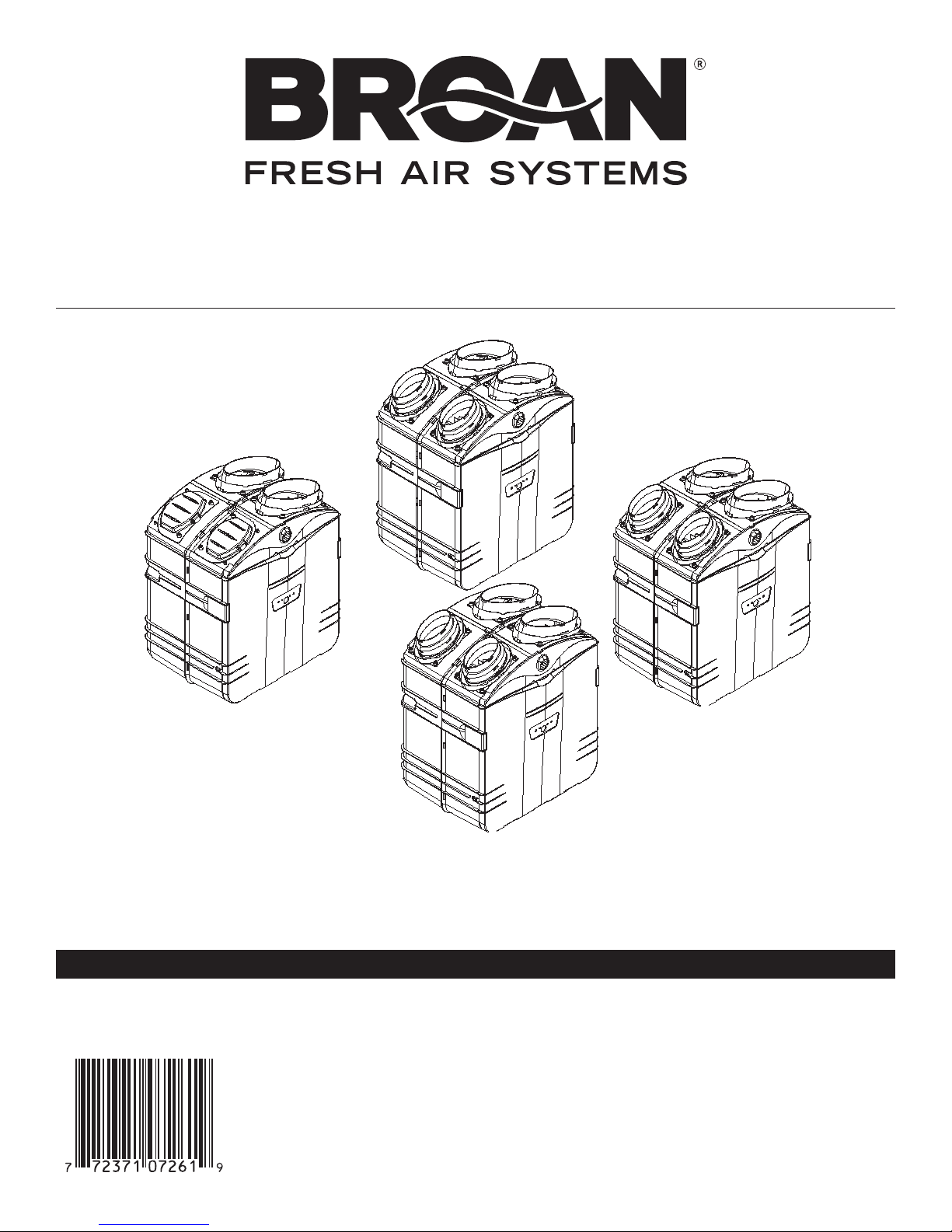
HEPA Filtration
and Fresh Air
Ventilation*
GSVH1K
INSTALLATION INSTRUCTIONS MANUAL
RESIDENTIAL USE ONLY.
INSTALLER: LEAVE THIS MANUAL WITH CONSUMER.
*Patents pending
HEPA Filtration,
Fresh Air and
Heat Recovery
Ventilation*
GSHH3K
HEPA Filtration,
Fresh Air and
Energy Recovery
Ventilation*
GSEH3K
HEPA
Filtration*
GSFH1K
READ AND SAVE THESE INSTRUCTIONS
Broan-NuTone LLC; Hartford, Wisconsin www.broan.com 800-558-1711
REGISTER YOUR PRODUCT ON LINE AT: www.broan.com/register
For additional information - visit www.Broan.com
04326 rev. 7
99043105
Page 2
ABOUT THIS MANUAL
Congratulation! Your purchase of this whole-house HEPA filtration, with optional ventilation will allow you and your family to enjoy clean
and healthy air throughout your home for years to come!
Please read this manual thoroughly.
Several models are described in this publication. Some details of your unit may be slightly different than the ones shown, as the illustration
are typical ones.
Please take note that this manual uses the following symbols to emphasize particular information:
NOTE: Indicates supplementary information needed to fully complete an instruction.
We welcome any suggestions you may have concerning this manual and/or the product, or ways to better serve you. Please forward all
correspondence at the address below:
Broan-NuTone LLC
Indoor Air Quality Marketing
926 W. State St.,
Hartford, WI 53027
1-800-558-1711
WARNING
Identifies an instruction which, if not followed, might cause serious personal injuries including possibility of death.
CAUTION
Denotes an instruction which, if not followed, may severely damage the unit and/or its components.
ABOUT THESE UNITS
WARNING
TO REDUCE THE RISK OF FIRE, ELECTRIC SHOCK, OR INJURY TO PERSON(S) OBSERVE THE FOLLOWING:
1. This unit is intented for residential installation only.
2. Installation must be done in accordance with all applicable codes and standards, including fire-rated construction codes
and standards.
3. This unit is not designed to provide combustion and/or dilution air for fuel-burning appliances.
4. Do not install in a cooking area or connect directly to an appliance.
5. Before replacing filters, servicing or cleaning unit, disconnect the power cord from electrical outlet.
6. When cutting or drilling into wall or ceiling, do not damage electrical wiring or other hidden utilities.
7. Do not use this unit with any solid-state speed control device other than wall controls ACCGSC1 or 40425, provided
with the unit.
8. This unit must be grounded. The power supply cord has a 3-prong grounding plug for your personal safety. It must be
plugged into a mating 3-prong grounding receptacle, grounded in accordance with the national electrical code and local
codes and ordinances. Do not remove the ground prong. Do not use an extension cord.
9. This unit must be installed in a weatherized location out of direct sunlight and protected from the elements.
10. Use this unit only in the manner intended by the manufacturer. If you have questions, contact the manufacturer at the
address or telephone number listed in this document.
11. When performing installation, servicing or cleaning the unit, it is recommended to wear safety glasses and gloves.
12. When the federal, provincial or state legislation comprises more restrictive installation and/or certification requirements,
the aforementioned requirements prevail on those of this document and the installer agrees to conform to these at his
own expenses.
CAUTION
1. For general filtration and ventilation use only. Do not use to exhaust hazardous or explosive materials and vapors.
2. Intended for residential installation only in accordance with the requirements of NFPA 90B.
3. For GSVH1K, GSHH3K and GSEH3K units only: Be sure to duct air outside. - Do not intake / exhaust air into spaces with
in walls or ceiling or into attics, crawl spaces, or garage.
4. Do not run any air ducts directly above or closer than 2 ft (0.61 m) to any furnace or its supply plenum, boiler, or other heat
producing appliance. If a duct has to be connected to the furnace return plenum, it must be connected not closer than 2 ft
(0.61 m) from this plenum connection to the furnace.
5. The ductwork is intended to be installed in compliance with all local and national codes that are applicable.
6. To avoid prematurate clogged filters, turn OFF the unit during construction or renovation.
7. Please read the unit specification label on the product for further information and requirements.
8. During snow storm, turn GSVH1K unit OFF to avoid water build-up in the unit. For GSEH3K and GSHH3K, operate these
units in recirculation mode.
9. At least once in a year, the unit mechanical and electronic parts should be inspected by qualified service personnel.
!
!
NOTE: The energy recovery ventilator GSEH3K is designed to assist in the management of humidity introduced into the home.
In extreme humidity conditions, the use of additional dehumidification may be desirable. Quickly remove all excess moisture and
keep areas clean.
- 2 -
Page 3

1. BEFORE STARTING . . . . . . . . . . . . . . . . . . . . . . . . . . . . . . . . . . . . . . . . . . . . . . . . . . . . . . . . .4
1.1 Inspect the Content of the Box . . . . . . . . . . . . . . . . . . . . . . . . . . . . . . . . . . . . . . . . . . . . . . . . . . . . . . . . . . . .4
2. TECHNICAL DATA . . . . . . . . . . . . . . . . . . . . . . . . . . . . . . . . . . . . . . . . . . . . . . . . . . . . . . . .4-6
2.1 Dimensions and Air Distribution Ports . . . . . . . . . . . . . . . . . . . . . . . . . . . . . . . . . . . . . . . . . . . . . . . . . . . . . .5
2.2 Ventilation Performances . . . . . . . . . . . . . . . . . . . . . . . . . . . . . . . . . . . . . . . . . . . . . . . . . . . . . . . . . . . . . . .5-6
2.3 Mounting and Servicing Considerations . . . . . . . . . . . . . . . . . . . . . . . . . . . . . . . . . . . . . . . . . . . . . . . . . . . . .6
3. RECOVERY NEEDS ACCORDING TO GEOGRAPHICAL LOCATION . . . . . . . . . . . . . . . . . . . . . . . . . .7
4. PLANNING THE INSTALLATION . . . . . . . . . . . . . . . . . . . . . . . . . . . . . . . . . . . . . . . . . . . . . . . .7-8
4.1 Planning of the ductwork . . . . . . . . . . . . . . . . . . . . . . . . . . . . . . . . . . . . . . . . . . . . . . . . . . . . . . . . . . . . . . . .8
5. TYPICAL INSTALLATIONS . . . . . . . . . . . . . . . . . . . . . . . . . . . . . . . . . . . . . . . . . . . . . . . . . . .8-13
5.1 GSFH1K Unit Installations . . . . . . . . . . . . . . . . . . . . . . . . . . . . . . . . . . . . . . . . . . . . . . . . . . . . . . . . . . . . . . .9
5.2 GSVH1K, GSHH3K and GSEH3K Units Installations . . . . . . . . . . . . . . . . . . . . . . . . . . . . . . . . . . . . . . . . .10
5.3 Stand Alone Installation . . . . . . . . . . . . . . . . . . . . . . . . . . . . . . . . . . . . . . . . . . . . . . . . . . . . . . . . . . . . . .11-12
5.4 Central Draw Point Installation . . . . . . . . . . . . . . . . . . . . . . . . . . . . . . . . . . . . . . . . . . . . . . . . . . . . . . . . . . .12
5.5 Return-to-Return Installation . . . . . . . . . . . . . . . . . . . . . . . . . . . . . . . . . . . . . . . . . . . . . . . . . . . . . . . . . . . .13
6. INSTALL THE UNIT . . . . . . . . . . . . . . . . . . . . . . . . . . . . . . . . . . . . . . . . . . . . . . . . . . . . . .14-25
6.1 Tools and Materials . . . . . . . . . . . . . . . . . . . . . . . . . . . . . . . . . . . . . . . . . . . . . . . . . . . . . . . . . . . . . . . . . . . .14
6.2 Mount the Ports on the Unit . . . . . . . . . . . . . . . . . . . . . . . . . . . . . . . . . . . . . . . . . . . . . . . . . . . . . . . . . . . . .14
6.3 Installation Using Isolator Pads . . . . . . . . . . . . . . . . . . . . . . . . . . . . . . . . . . . . . . . . . . . . . . . . . . . . . . . . . .14
6.4 For Suspended Applications . . . . . . . . . . . . . . . . . . . . . . . . . . . . . . . . . . . . . . . . . . . . . . . . . . . . . . . . . . 14-16
6.5 Installing 8“ Ducts and Registers . . . . . . . . . . . . . . . . . . . . . . . . . . . . . . . . . . . . . . . . . . . . . . . . . . . . . .16-18
6.6 Installing Insulated Flexible Ducts to Tandem® Transition . . . . . . . . . . . . . . . . . . . . . . . . . . . . . . . . . . . . . . 19
6.7 Installing AirDuo™ Exterior Hood . . . . . . . . . . . . . . . . . . . . . . . . . . . . . . . . . . . . . . . . . . . . . . . . . . . . . 19-21
6.8 Installing Two exterior Hoods . . . . . . . . . . . . . . . . . . . . . . . . . . . . . . . . . . . . . . . . . . . . . . . . . . . . . . . . . 21-22
6.9 Connection to the 5’’ to 6’’ Oval Ports of the Unit . . . . . . . . . . . . . . . . . . . . . . . . . . . . . . . . . . . . . . . . . . . . 23
6.10 Connecting the Drain . . . . . . . . . . . . . . . . . . . . . . . . . . . . . . . . . . . . . . . . . . . . . . . . . . . . . . . . . . . . . . . . . . 24
6.11 Low Temperature Applications Below Freezing (32°F or 0°C) . . . . . . . . . . . . . . . . . . . . . . . . . . . . . . . . 24-25
7. CONTROLS . . . . . . . . . . . . . . . . . . . . . . . . . . . . . . . . . . . . . . . . . . . . . . . . . . . . . . . . . . .26-31
7.1 Main Switch . . . . . . . . . . . . . . . . . . . . . . . . . . . . . . . . . . . . . . . . . . . . . . . . . . . . . . . . . . . . . . . . . . . . . . . . . 26
7.2 Wall Controllers . . . . . . . . . . . . . . . . . . . . . . . . . . . . . . . . . . . . . . . . . . . . . . . . . . . . . . . . . . . . . . . . . . . . . 26
7.3 Installation of the ACCGSC1 Wall Controller . . . . . . . . . . . . . . . . . . . . . . . . . . . . . . . . . . . . . . . . . . . . . . . . 27
7.4 Installation of the 40425 Wall Controller . . . . . . . . . . . . . . . . . . . . . . . . . . . . . . . . . . . . . . . . . . . . . . . . . . . 28
7.5 Wall Controllers Connection to the Unit . . . . . . . . . . . . . . . . . . . . . . . . . . . . . . . . . . . . . . . . . . . . . . . . . . . 29
7.6 Operating ACCGSC1 Controller . . . . . . . . . . . . . . . . . . . . . . . . . . . . . . . . . . . . . . . . . . . . . . . . . . . . . . . . . 30
7.7 Operating 40425 Controller . . . . . . . . . . . . . . . . . . . . . . . . . . . . . . . . . . . . . . . . . . . . . . . . . . . . . . . . . . 30-31
8. BALANCING PROCEDURE . . . . . . . . . . . . . . . . . . . . . . . . . . . . . . . . . . . . . . . . . . . . . . . . . . .32
8.1 What You Need to Balance the Unit . . . . . . . . . . . . . . . . . . . . . . . . . . . . . . . . . . . . . . . . . . . . . . . . . . . . . . .32
8.2 Preliminary stages for Balancing the Unit . . . . . . . . . . . . . . . . . . . . . . . . . . . . . . . . . . . . . . . . . . . . . . . . . .32
8.3 Installation of Flow Collar . . . . . . . . . . . . . . . . . . . . . . . . . . . . . . . . . . . . . . . . . . . . . . . . . . . . . . . . . . . . . . .32
8.4 Balancing Procedure . . . . . . . . . . . . . . . . . . . . . . . . . . . . . . . . . . . . . . . . . . . . . . . . . . . . . . . . . . . . . . . . . .32
9. MAINTENANCE . . . . . . . . . . . . . . . . . . . . . . . . . . . . . . . . . . . . . . . . . . . . . . . . . . . . . . . .33-35
9.1 Semi-Annual Maintenance (Essential) . . . . . . . . . . . . . . . . . . . . . . . . . . . . . . . . . . . . . . . . . . . . . . . . . .33-34
9.2 Annual Maintenance . . . . . . . . . . . . . . . . . . . . . . . . . . . . . . . . . . . . . . . . . . . . . . . . . . . . . . . . . . . . . . . . . . .35
9.3 Optional Alpine/pine Filter . . . . . . . . . . . . . . . . . . . . . . . . . . . . . . . . . . . . . . . . . . . . . . . . . . . . . . . . . . . . . . .35
10. TROUBLESHOOTING . . . . . . . . . . . . . . . . . . . . . . . . . . . . . . . . . . . . . . . . . . . . . . . . . . . . . . .35
11. WARRANTY . . . . . . . . . . . . . . . . . . . . . . . . . . . . . . . . . . . . . . . . . . . . . . . . . . . . . . . . . . . . .36
TABLE OF CONTENTS
- 3 -
Page 4
• Inspect the exterior of the unit for shipping damage. Ensure there is no damage to the door, door latches, main switch, etc.
1) Cardboard strip
• Inspect the interior of the unit for damage. Ensure the blower assembly, heat recovery core (model GSHH3K), energy recovery core
(model GSEH3K), insulation, dampers (models GSVH1K, GSHH3K and GSEH3K), prefilter, HEPA filter, etc. are all intact.
• If the unit was damaged during shipping, contact your local distributor, or Broan-NuTone at 1-800-558-1711.
1. BEFORE STARTING
1.1 INSPECT THE CONTENTS OF THE BOX
NOTE: Due to our ongoing commitment to product quality and innovation, all specifications are subjected to change without notice.
VD0126
CAUTION
Remove the cardboard strip inside the unit (if applicable).
WARNING
To avoid risk of suffocation, discard the plastic bag wrapping the unit.
!
2. TECHNICAL DATA
GSFH1K GSVH1K GSHH3K GSEH3K
HEPA Filtration HEPA Filtration, HEPA Filtration,
Models HEPA Filtration & Fresh Air Fresh Air & Fresh Air &
Ventilation Heat Recovery Energy Recovery
Ventilation Ventilation
Weight 34 lb (15.4 kg) 36 lb (16.3 kg) 40 lb (18.2 kg) 40 lb (18.2 kg)
Oval shaped duct collars
for non-insulated ducts fits two 8” round ducts
to inside
Oval shaped duct collars
for insulated ducts N/A fits two 5” or 6” round ducts
to outside
Installation: Suspended Chains, springs and hooks (provided with the unit)
or rest on a shelf or floor: or 4 pads (provided with the unit)
Electrical Supply 120 Volts AC, 60 Hz
Power Consum. (Boost) 170 Watts 224 Watts 229 Watts 224 Watts
Power Consum. (Normal) 132 Watts 152 Watts 170 Watts 170 Watts
1
- 4 -
Page 5
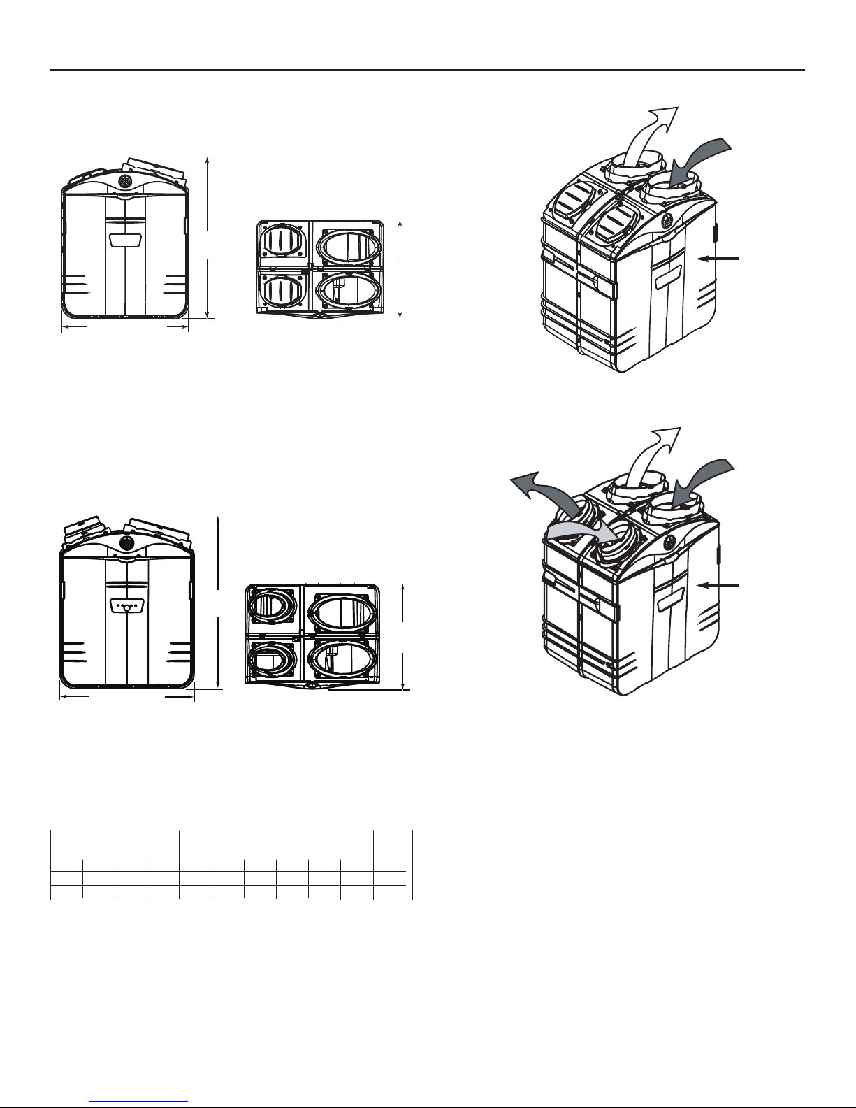
HEPA FILTRATION UNIT AND FRESH AIR VENTILATION,
MODEL GSVH1K
HEPA FILTRATION, FRESH AIR AND HEAT RECOVERY
VENTILATION, MODEL GSHH3K
HEPA FILTRATION, FRESH AIR AND ENERGY RECOVERY
VENTILATION, MODEL GSEH3K
FRONT VIEW TOP VIEW
2. TECHNICAL DATA (CONT’D)
- 5 -
2.1 DIMENSIONS AND AIR DISTRIBUTION PORTS
HEPA FILTRATION UNIT, MODEL GSFH1K
FRONT VIEW TOP VIEW
17.8''
(452 mm
29''
(737 mm)
22.9'' (581 mm)
VK0047
29.4''
(748 mm)
VK0048A
17.8''
(452 mm)
22.9'' (581 mm)
VF0029
STALE AIR
FROM
BUILDING
STALE AIR
TO
OUTSIDE
FRESH
AIR FROM
OUTSIDE
FRESH AND FILTERED
AIR TO BUILDING
VF0033
STALE AIR
FROM
BUILDING
FILTERED AIR
TO BUILDING
FRONT
FRONT
2.2 VENTILATION PERFORMANCES
2.2.1 GSVH1K VENTILATION PERFORMANCES
NOTE: all tests performed at high speed.
EXT. STATIC NET VENTILATION GROSS AIR FLOW
POWER
PRESSURE AIRFLOW SUPPLY EXHAUST FILTERED
Pa
50
100
in.w.g.
0.2
0.4
L/s
52
49
cfm
110
104
L/s
56
52
cfm
118
111
L/s
54
49
cfm
115
104
L/s
132
121
cfm
279
257
Watts
231
224
Page 6
- 6 -
2. TECHNICAL DATA (CONT’D)
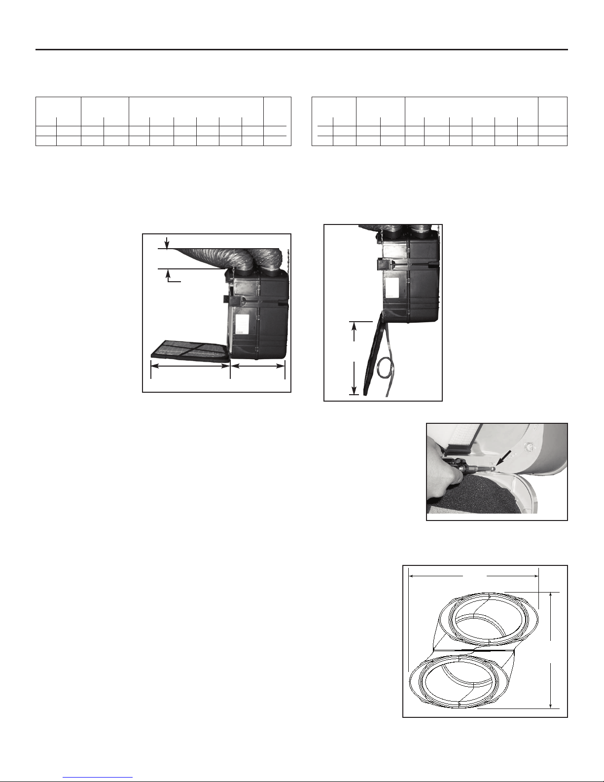
2.3 MOUNTING AND SERVICING CONSIDERATIONS
• The two following pictures are showing the minimum clearance needed to open the door completely.
22.5” 15.75”
(572 mm) (400 mm)
VD0117
VD0116
22”
(559 mm)
NOTES: 1. The unit door is removable. To do so, remove the stopper (A) located on the right side
of the door hinge, then, slide the door out of its hinge. For servicing, a minimum of 15’’
(381 mm) clearance from any obstruction in front of the unit is sufficient to open the door
and remove it.
2. A minimum of 8” (203 mm) clearance from any obstruction on top of the unit is required
for the ductwork radius turn.
8”
(203 mm)
VD0118A
8¾”
222 mm
9¾”
248 mm
• The joist opening needed to install the Tandem®transition must be 9¾” (248 mm)
minimum. Also, the maximum height of the Tandem®transition is 8¾” (222 mm).
See Tandem®transition end view beside.
NOTES: 1. If there is not enough space to use the Tandem®transition, the optional exterior
single hood must be installed to bring the fresh outside air to the unit.
See Section 6.8.
2. When installing a HEPA Filtration model GSFH1K, there is no Tandem® transition.
2.2 VENTILATION PERFORMANCES (CONT’D)
2.2.2 GSHH3K V
ENTILATION PERFORMANCES 2.2.3 GSEH3K VENTILATION PERFORMANCES
NOTE: all tests performed at high speed.
EXT. STATIC NET VENTILATION GROSS AIR FLOW
POWER
PRESSURE AIRFLOW SUPPLY EXHAUST FILTERED
Pa
50
100
in.w.g.
0.2
0.4
L/s
52
49
cfm
110
103
L/s
58
55
cfm
124
116
L/s
57
51
cfm
121
108
L/s
131
119
cfm
277
252
Watts
237
229
EXT. STATIC NET VENTILATION GROSS AIR FLOW
POWER
PRESSURE AIRFLOW SUPPLY EXHAUST FILTERED
Pa
50
100
in.w.g.
0.2
0.4
L/s
57
53
cfm
122
113
L/s
50
48
cfm
105
102
L/s
59
55
cfm
125
117
L/s
127
120
cfm
270
254
Watts
227
224
VD0170
A
Page 7
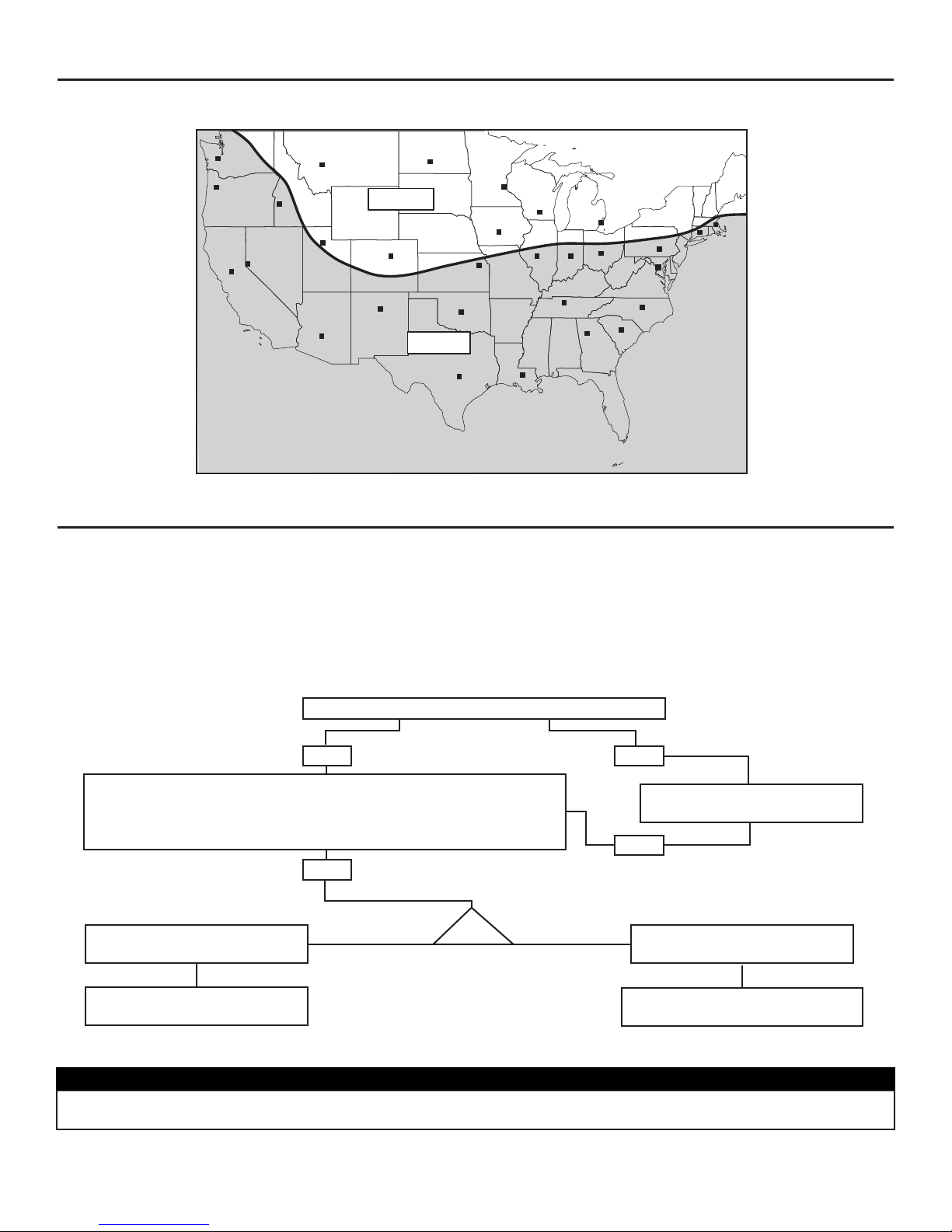
3. RECOVERY NEEDS ACCORDING TO GEOGRAPHICAL LOCATION
- 7 -
When recovery is important, it can be hard to find the appropriate unit. Use the map below to determine which between heat
recovery (GSHH3K model) or energy recovery (GSEH3K model) will satisfy the specific needs of the consumers.
HELENA
OLYMPIA
SALEM
BOISE
BISMARCK
SALT LAKE CITY
ST. PAU L
DES MOINES
MADISON
HARRISBURG
SACRAMENTO
DENVER
TOPEKA
DETROIT
INDIANAPOLIS
SANTA FE
SPRINGFIELD
OKLAHOMA CITY
PHOENIX
COLUMBUS
NASHVILLE
ATLANTA
BATON ROUGE
AUSTIN
COLUMBIA
RALEIGH
WASHINGTON
HARTFORD
BOSTON
ZONE A
ZONE B
RENO
When exchanging air with outside:
ZONE A: GSHH3K unit recommended*
ZONE B: GSEH3K unit recommended
* In ZONE A, the GSEH3K unit may be used, but below 16F,
the duration of exchanging air with outside will decrease.
VN0004A
The Broan Fresh Air Systems units are versatile appliances capable of delivering filtered air (model GSFH1K) or both filtered and
fresh air to your home (models GSVH1K, GSHH3K and GSEH3K). Because each installation is different, it is recommended you take
the time to plan your installation. The three main areas to plan for are:
• Where to locate the Broan Fresh Air Systems unit
• How to pick-up the air from the room and distribute the filtered or fresh/filtered air
• Where to bring fresh air from outside and exhaust stale air to outside (models GSVH1K, GSHH3K and GSEH3K).
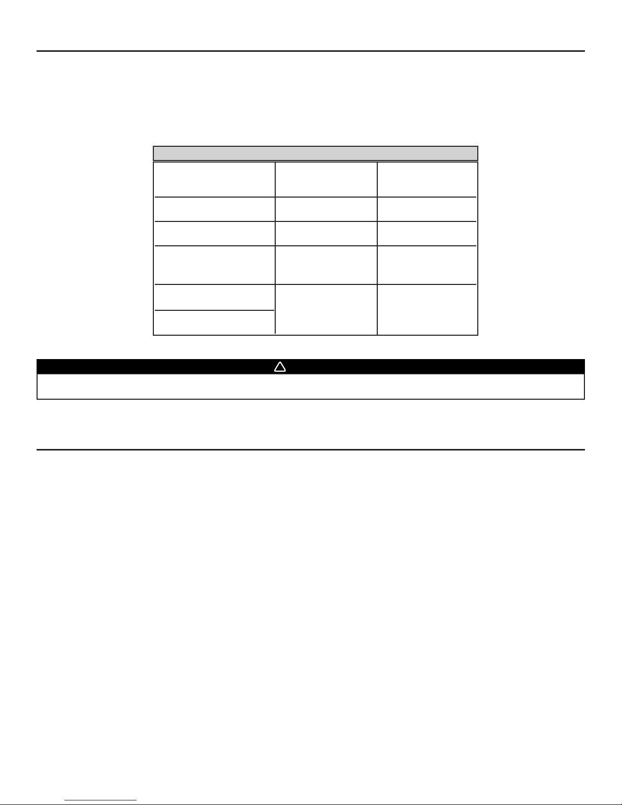
Use the following chart to determine the appropriate installation method for the unit.
Example: Basement installation
in Section 5.4.1
Example: Crawl space installation
in Section 5.5.1
CAUTION
Do not install duct or duct connector directly above the furnace. Do not connect the plenum connection closer than 2’ (0.61m)
to the furnace, as measured along the length of the duct.
The Return-to-Return
installation can be performed.
The Central Draw Point
installation can be performed.
Is the house equipped with a furnace or air handler?
4. PLANNING THE INSTALLATION
YES
NO
Use Stand Alone installation.
See Section 5.3.
NO
YES
Is there enough space to connect the unit duct(s) to the existing
furnace or air handler ductwork? (The unit duct connection can be
performed on the cold air return duct, at a minimum linear distance
of 2’ (0.61 m) from the furnace/air handler.)
OR
Page 8
4
.1 PLANNING OF THE DUCTWORK
• Keep it simple. Plan for a minimum of bends and joints.
• Keep the length of insulated ducts to the outside of home to a minimum.(not for HEPA Filtration model GSFH1K).
• Do not ventilate crawl spaces or cold rooms.
• If the house has two floors or more, be sure to plan for at least one exhaust register on the highest lived-in level.
Use the table below to plan the flexible ducts length.
4. PLANNING THE INSTALLATION (CONT’D)
- 8 -
Maximum Maximum
recommended length recommended length
to reach 105 cfm to reach 95 cfm
Insulated fresh air duct
from outside (6” diameter)
up to 10’ from 10’ to 20’
Insulated exhaust air duct
to outside (6” diameter)
up to 10’ from 10’ to 20’
Recommended Recommended
maximum length maximum length
to reach 270 cfm to reach 240 cfm
Stale air duct from inside
(8” diameter) Combined: 40’ Combined: 60’ with
Filtered air duct to inside stale air duct not to
(8” diameter) exceed 36’
FLEXIBLE DUCT LENGTH TABLE
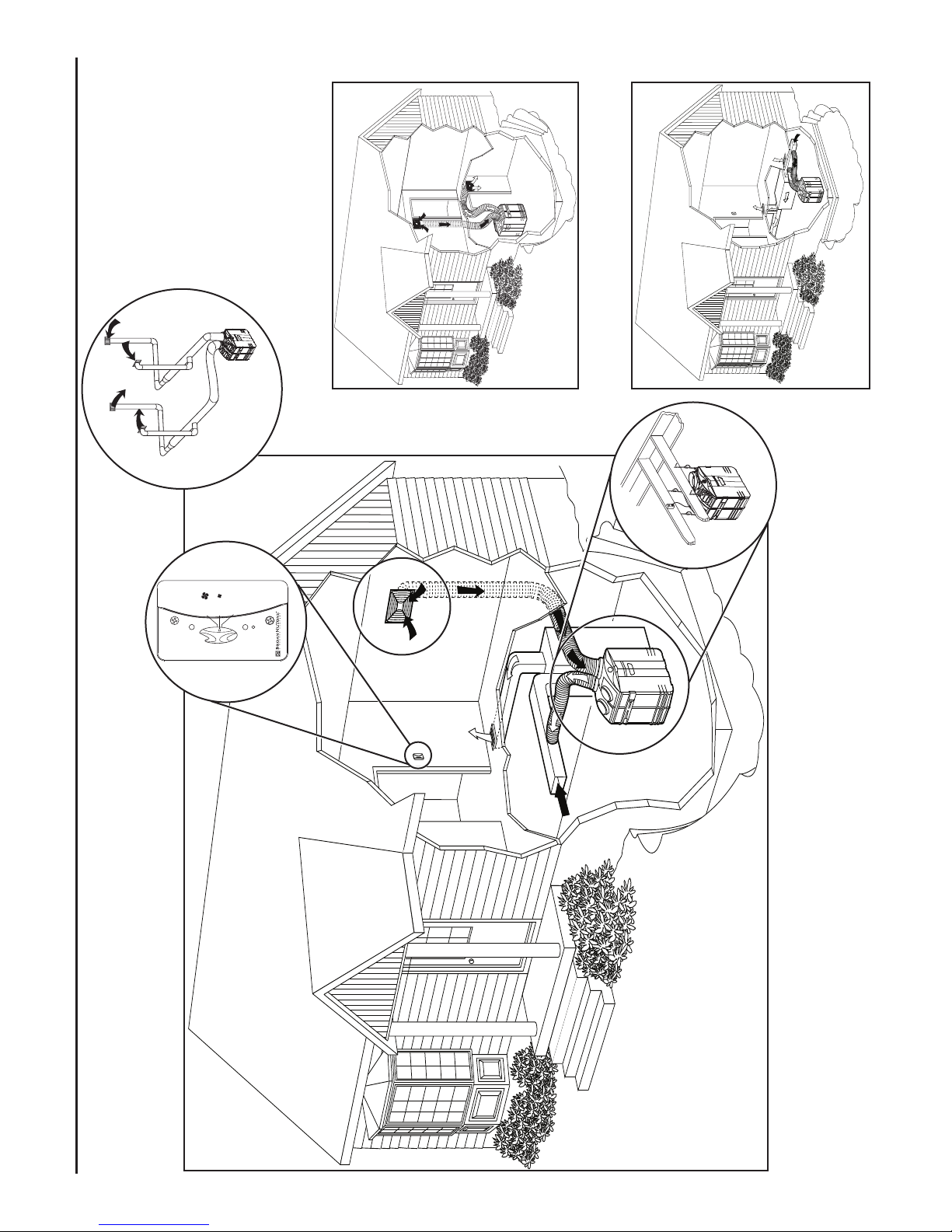
5. TYPICAL INSTALLATIONS
Installations may vary according to the model number, the product orientation (vertical or horizontal) and the location in the home where
the unit is installed. Use the following illustrations as guidelines to help you decide the appropriate installation.
The unit allows for multi positional mounting (vertical or horizontal). It may be hung to the joists (preferred method), or it may be laid down
on one of three surfaces, and installed either vertically or horizontally.
NOTE: For more details, see Points 5.3 and 5.4 in Section 5 INSTALL THE UNIT.
In every case, bathroom fans and a range hood should be used as spot ventilation to exhaust stale air. Also, for homes with more than
one level, we recommend placing one exhaust register at the highest lived-in level.
There are three installation methods: Stand Alone, Central Draw Point* and Return-to-Return*.
* Different connections to a forced air system.
Multiple furnaces or air handlers may require installation of Broan Fresh Air Systems on each system for maximum IAQ benefit.
NOTE: A grounded three-prong electrical outlet has to be available within 3 feet from the unit.
WARNING
Do not attempt to recover in any ways the exhaust air from a dryer or a range hood. This would cause clogging of the filters
and recovery module (if applicable); this is also a fire hazard. Not following this warning will void the warranty.
!
Page 9
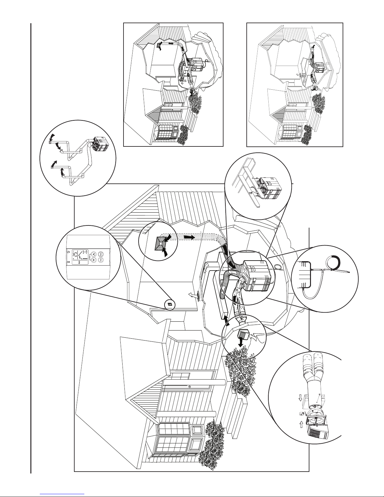
5.1 GSFH1K UNIT INSTALLATIONS
VH0038
INSTALLATION TYPE SHOWN: CENTRAL DRAW POINT
SEE SECTION 5.4.1
STA ND ALONE INSTALLATION
SEE SECTION 5.3.1
RETURN-TO-RETURN INSTALLATION
SEE SECTION 5.5.1
HOW TO HANG THE UNIT
SEE SECTION 6.4
SECTION 7: CONTROLS
INSTALLING 8’’ DUCTS AND
REGISTERS
SEE SECTIONS 6.5
VH0037
VH0047
VD0129
VC0059
High
Low
OFF
Reset Filter
Filter Maintenance
Power
- 9 -
VI0013
NOTE: OTHER INSTALLATIONS SHOWN NEXT PAGES
Page 10
5.2 GSVH1K, GSHH3K AND GSEH3K UNITS INSTALLATIONS
VH0068
INSTALLATION TYPE SHOWN: CENTRAL DRAW POINT
SEE SECTION 5.4.1
STA ND ALONE INSTALLATION
SEE SECTION 5.3.1
RETURN-TO-RETURN INSTALLATION
SEE SECTION 5.5.1
HOW TO HANG THE UNIT
SEE SECTION 6.4
CONNECTING THE DRAIN
SEE SECTION 6.10
SECTION 7: CONTROL
VH0039
VH0043
VD0150
VO0029
VC0098
- 10 -
INSTALLING 8’’ DUCTS AND
REGISTERS
SEE SECTIONS 6.5
VI0011
VD0149
OUTDOOR CONNECTION
SEE SECTIONS 6.6, 6.7, 6.8 AND 6.9
NOTE: OTHER INSTALLATIONS SHOWN
NEXT PAGES
Page 11
- 11 -
5. TYPICAL INSTALLATIONS (CONT’D)
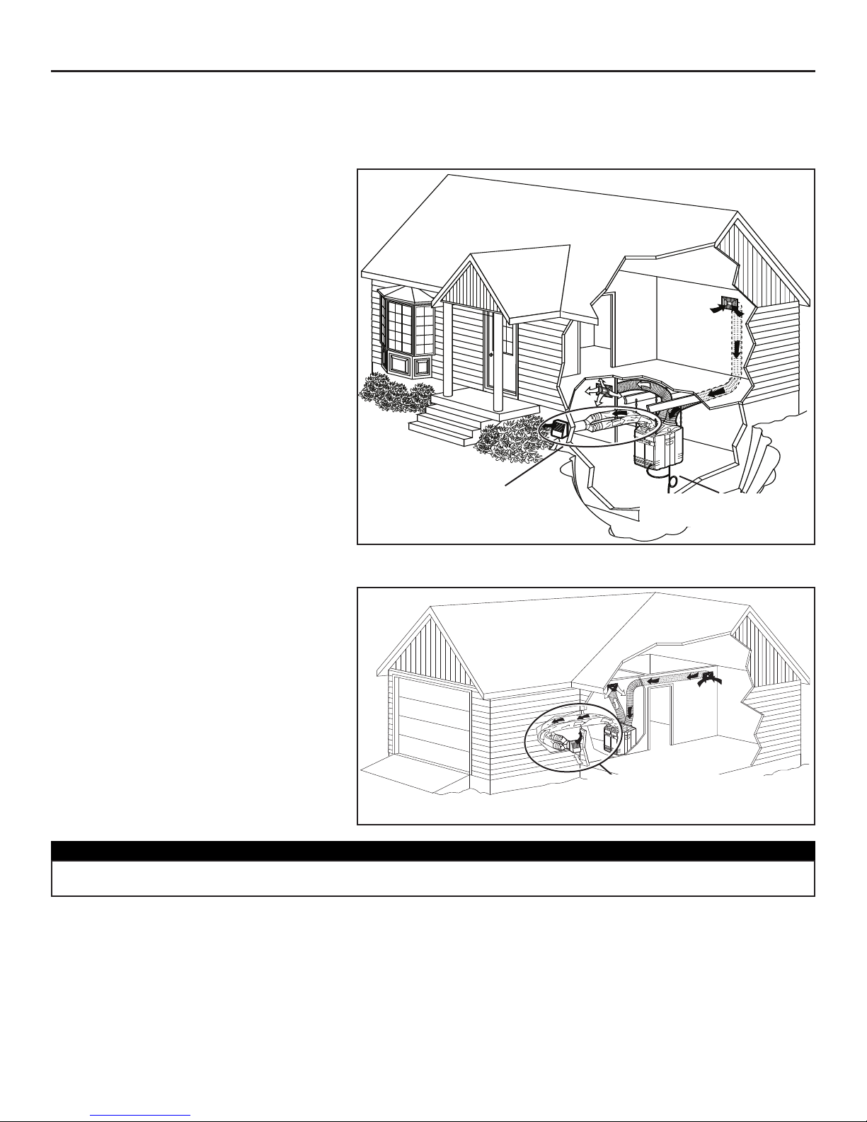
5.3.1 BASEMENT
• Ideal for homes without a central furnace
in the basement. Allows filtration and a
better air circulation throughout the house.
• Easy access to perform the periodic filter
maintenance and servicing.
• Offers an ambient temperature above
freezing (32°F - 0°C).
• The HEPA Filtration model GSFH1K has
no connection to the outside, so all parts
encircled are not required.
INSTALLATION CONSIDERATIONS:
• Installing the unit near an exterior wall will
shorten the length of the insulated ducts
(not necessary for HEPA Filtration only
model GSFH1K).
• If a HEPA Filtration Fresh Air & Heat
Recovery Ventilation model GSHH3K is
installed, a water drain must be close to
collect the run-off.
5.3 STAN D ALONE INSTALLATION
(Primarily for homes with no central air mover or equipped with wall furnaces, radiant hot water or electric baseboard heating.)
VH0039
Only for the models GSVH1K,
GSHH3K and GSEH3K that
use fresh outside air.
Drain required only for the
GSHH3K model.
5.3.2 GARAGE CLOSET
• Ideal for homes without a central furnace,
or limited space applications, allows filtration
and a better air circulation throughout the
house.
• Easy access to perform the periodic
maintenance (twice a year).
• The HEPA Filtration model GSFH1K has
no connection to outside, so all parts
encircled are not required.
VH0046
Only for the models GSVH1K,
GSHH3K and GSEH3K that
use fresh outside air.
CAUTION
When the ambient temperature for the unit location is below freezing (32°F - 0°C), the unit must run continuously to prevent
condensation.
INSTALLATION CONSIDERATIONS:
• Installing the unit near an exterior wall will shorten the length of the insulated ducts
(not necessary for HEPA Filtration model GSFH1K).
• If a HEPA Filtration Fresh Air & Heat Recovery Ventilation model GSHH3K is installed, a water drain must be close to collect
the run-off.
• All ducts must be insulated.
• For the HEPA Filtration, Fresh Air & Heat Recovery Ventilation (GSHH3K) and the HEPA Filtration, Fresh Air & Energy
Recovery Ventilation (GSEH3K) models only, if the ambient temperature around the unit drops below freezing (32°F - 0°C),
go to Section 6.11 (Low Temperature Applications) for instructions on drain line protection (GSHH3K only) and other cold
environment installation details.
Page 12
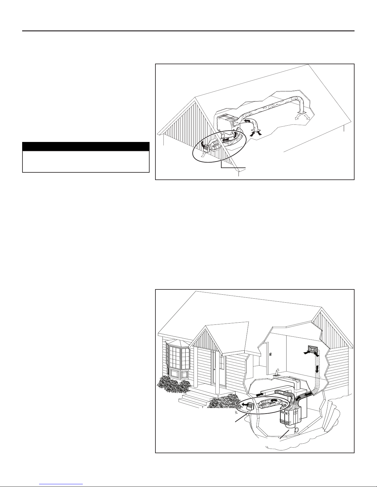
5. TYPICAL INSTALLATIONS (CONT’D)
- 12 -
5.3 STAN D ALONE INSTALLATION (CONT’D)
(Primarily for homes with no central air mover or equipped with wall furnaces, radiant hot water or electric baseboard heating.)
5.3.3 ATTIC
• Ideal for homes without a central furnace,
or limited space applications, allows filtration
and a better air circulation throughout the
house.
• Only one partition to go through to install
the registers.
• No visible ducts.
• The HEPA Filtration model GSFH1K has
no connection to the outside, so all parts
encircled are not required.
CAUTION
When the ambient temperature for the unit
location is below freezing (32°F - 0°C), the unit
must run continuously to prevent condensation.
VH0054
INSTALLATION CONSIDERATIONS:
• Installing the unit near an exterior wall will shorten the length of the insulated ducts
(not necessary for HEPA Filtration only model GSFH1K).
• If a HEPA Filtration Fresh Air & Heat Recovery Ventilation model GSHH3K is installed, a water drain must be close to collect
the run-off.
• All ducts must be insulated.
• For the HEPA Filtration, Fresh Air & Heat Recovery Ventilation (GSHH3K) and the HEPA Filtration, Fresh Air & Energy
Recovery Ventilation (GSEH3K) models only, if the ambient temperature around the unit drops below freezing (32°F - 0°C),
go to Section 6.11 (Low Temperature Applications) for instructions on drain line protection (GSHH3K only) and other cold
environment installation details.
Only for the models GSVH1K, GSHH3K
and GSEH3K that use fresh outside air.
Drain required only for the GSHH3K
model .
5.4 CENTRAL DRAW POINT INSTALLATION
(Connection to a Forced Air System)
5.4.1 BASEMENT
• Simplified installation by using the home
existing ductwork to supply filtered air
throughout the house.
• The central draw point should be located
in the main area where most of the pollutants
are produced.
• The furnace/air handler does not need to
run continuously.
• Easy access to perform the periodic
maintenance (twice a year).
• Offers an ambient temperature above
freezing (32°F - 0°C).
• The HEPA Filtration model GSFH1K has
no connection to outside, so all parts
encircled are not required.
INSTALLATION CONSIDERATIONS:
• Installing the unit near an exterior wall will
shorten the length of the insulated ducts
(not necessary for HEPA Filtration only
model GSFH1K).
• If a HEPA Filtration Fresh Air & Heat
Recovery Ventilation model GSHH3K is
installed, a water drain must be close to
collect the run-off.
VH0040
Only for the models GSVH1K,
GSHH3K and GSEH3K that
use fresh outside air.
Drain required only for the GSHH3K.
Page 13
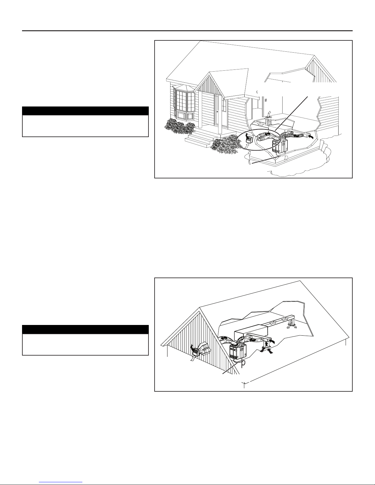
5. TYPICAL INSTALLATIONS (CONT’D)
5.5 RETURN-TO-RETURN INSTALLATION
(Connection to a Forced Air System)
5.5.1 CRAWL SPA C E
• Simplify the installation by using the
existing ductwork.
• Non-visible ducts.
• The HEPA Filtration model GSFH1K has
no connection to outside, so all parts
encircled are not required.
INSTALLATION CONSIDERATIONS:
• Installing the unit near an exterior wall will
shorten the length of the insulated ducts
(not necessary for HEPA Filtration model
GSFH1K).
• If a HEPA Filtration Fresh Air & Heat
Recovery Ventilation model GSHH3K is installed, a water drain must be close to collect the run-off.
• To avoid the cross-contamination and achieve highest efficiencies, the furnace / air handler blower must always be ON (or
the efficiency will be affected).
• The HEPA Filtration Fresh Air Ventilation model GSVH1K needs to be ON all the time, since it doesn’t have motorized
dampers. If this unit is OFF, then the furnace / air handler will draw cold outdoor air inside.
• All ducts must be insulated.
• For the HEPA Filtration, Fresh Air & Heat Recovery Ventilation (GSHH3K) and the HEPA Filtration, Fresh Air & Energy
Recovery Ventilation (GSEH3K) models only, if the ambient temperature around the unit drops below freezing (32°F - 0°C),
go to Section 6.11 (Low Temperature Applications) for instructions on drain line protection (GSHH3K only) and other cold
environment installation details.
VH0043
GSVH1K, GSHH3K and GSEH3K
that use fresh outside air.
Drain required only for the GSHH3K.
- 13 -
5.5.2 ATTIC
• Simplify the installation by using the
existing ductwork.
• Non-visible ducts.
• The HEPA Filtration model GSFH1K has
no connection to outside, so all parts
encircled are not required.
INSTALLATION CONSIDERATIONS:
• If a HEPA Filtration Fresh Air & Heat
Recovery Ventilation model GSHH3K is
installed, a water drain must be close to
collect the run-off.
• All ducts must be insulated.
• For the HEPA Filtration, Fresh Air & Heat Recovery Ventilation (GSHH3K) and the HEPA Filtration, Fresh Air & Energy
Recovery Ventilation (GSEH3K) models only, if the ambient temperature around the unit drops below freezing (32°F - 0°C),
go to Section 6.11 (Low Temperature Applications) for instructions on drain line protection (GSHH3K only) and other cold
environment installation details.
VH0051
Drain required only for the GSHH3K.
CAUTION
When the ambient temperature for the unit
location is below freezing (32°F - 0°C), the unit
must run continuously to prevent condensation.
CAUTION
When the ambient temperature for the unit
location is below freezing (32°F - 0°C), the unit
must run continuously to prevent condensation.
Page 14
- 14 -
6. INSTALL THE UNIT
6.1 TOOLS AND MAT ER IA L S
Here are the tools and materials needed to perform the installation:
• Phillips screwdriver no. 2 or Robertson no. 1
• Hammer and flat blade screwdriver (for plenum connection installation only, to make holes in existing metal duct)
• Scissors or utility knife (to cut duct tape)
• Duct tape
• Tin snips or metal shear (for plenum connection installation only, to cut ductwork)
• Aluminum duct tape (for plenum connection installation only, use SMACNA duct tape)
• Jigsaw (except for the HEPA Filtration model GSFH1K)
• Extension cord
• Caulking gun and caulking (except for the HEPA Filtration model GSFH1K)
• 6’’ Diameter insulated ducting (except for the HEPA Filtration model GSFH1K)
• 8’’ Diameter insulated ducting.
NOTE: A 3-prong grounded 120 volt AC power outlet must exist or be installed within 3 ft of the unit, prior to unit installation.
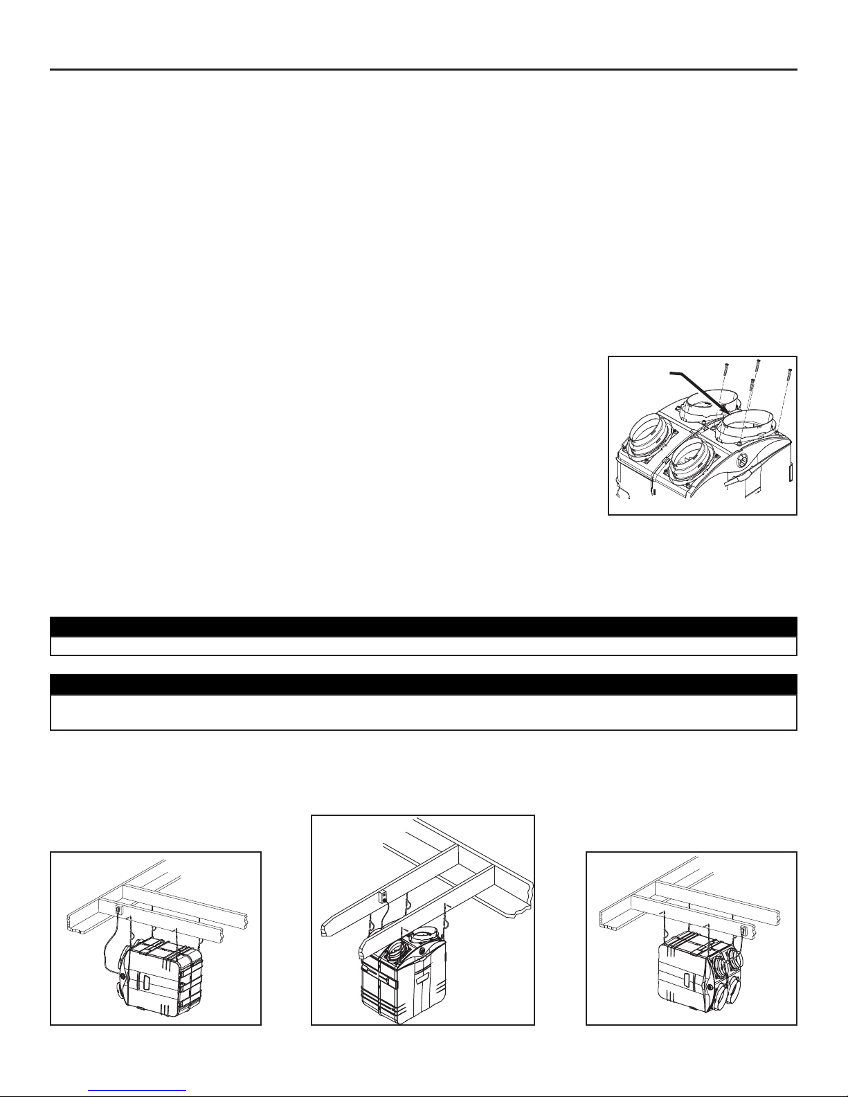
6.2 MOUNT THE PORTS ON THE UNIT
Mount the 8” oval ports and the 5” to 6” oval ports on the top of the unit using the screws provided in
the hardware box (4 screws no. 8 x 3/4” long per port).
NOTES: 1.Although 4 screws are provided and prefered; only 1 screw per port is required to meet
code.
2. The HEPA Filtration only model has no 5” to 6” oval ports.
3. Do not install the front 8’’ oval port (item 1 in illustration) at this time.
VO0018
6.3 INSTALLATION USING ISOLATOR PADS
If the unit cannot be hung, use the four adhesive square isolation pads provided with the unit. According to your needs and model (with
or without drain), you can install the unit either in vertical or horizontal position.
CAUTION
When a HEPA Filtration Fresh Air & Heat Recovery Ventilation unit model GSHH3K is installed with adhesive isolator pads,
keep a minimum clearance of 4” between the unit and the ground (or shelf) for the drain.
1
CAUTION
Make sure the unit is level.
VD0074
VERTICAL POSITION - ALL MODELS
6.4 FOR SUSPENDED APPLICATIONS
Use the four chains and springs in the hardware pack provided with the unit. According to your needs and model type, you can install the
unit either in a vertical or horizontal position.
H
ORIZONTAL POSITION (LEFT SIDE)
A
LL MODELS
HORIZONTAL POSITION (RIGHT SIDE)
MODEL GSFH1K ONLY
VD0075
VD0076
Page 15
- 15 -
6. INSTALL THE UNIT (CONT’D)
CAUTION
Make sure the unit is level.
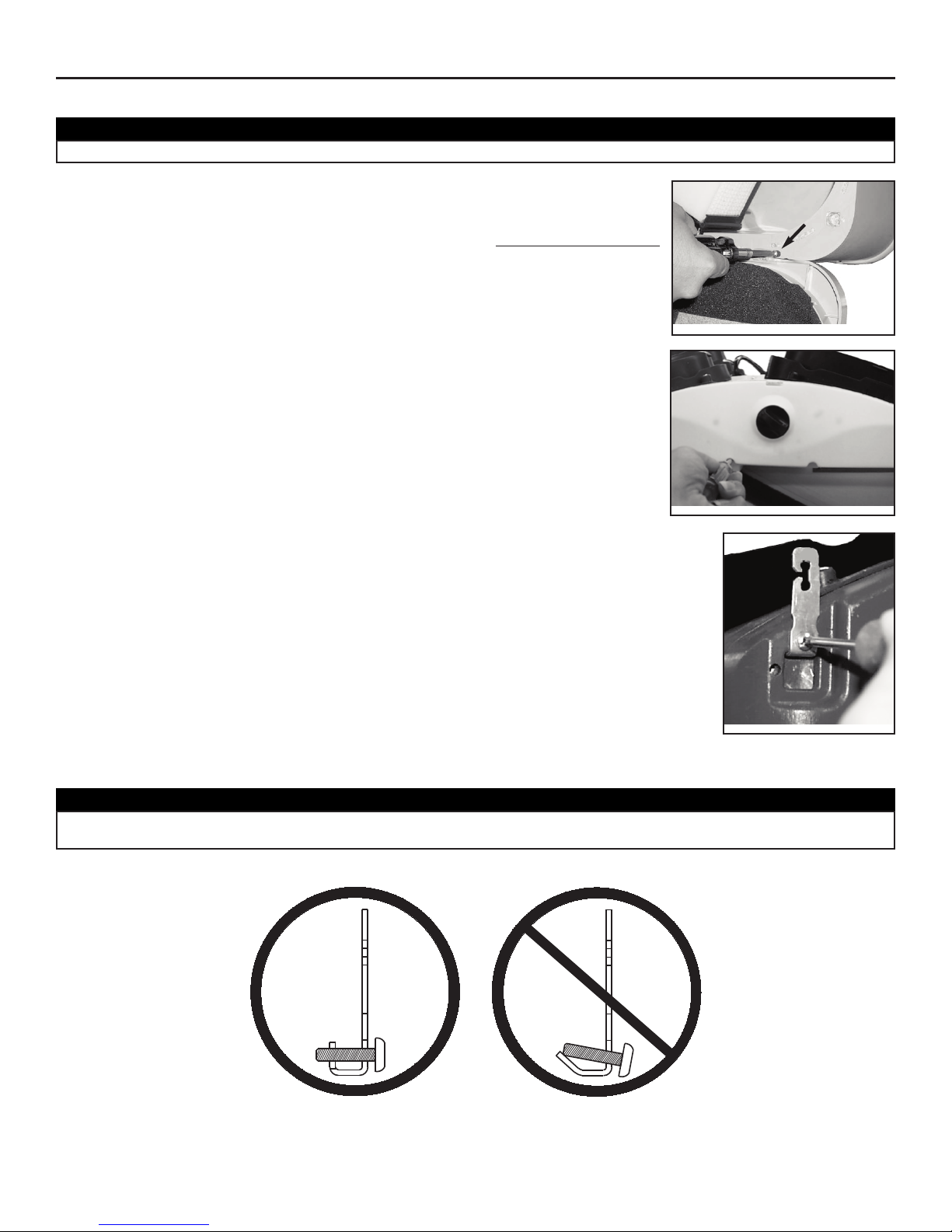
• Using a screwdriver, remove the two retaining screws of the front plate as shown, and
carefully remove the front plate from the unit.
• Insert the four hooks in the square holes and fix them to the unit using four screws no. 8-32 x 3/4”.
VO0019
VO0020
6.4 FOR SUSPENDED APPLICATIONS (CONT’D)
• To remove the door, verify the switch knob is in the OFF position in order to unlock the door.
Unlatch the door, using the 2 latches to open. Remove the stopper (A) located on the right
side of the door hinge, then, slide the door out of its hinge.
VD0170
A
CAUTION
Take care to insert the screws perpendicular to their hooks, in order to avoid potential damages due to loosen hooks.
See illustrations below.
VO006 3
DO DO NOT
Page 16
- 16 -
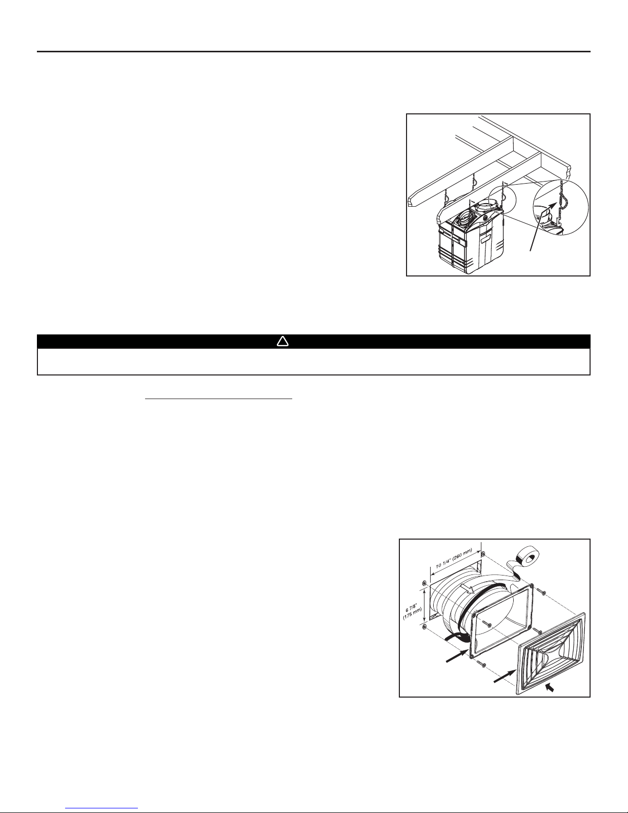
6.4 FOR SUSPENDED APPLICATIONS (CONT’D)
NOTE: To wire the wall control, go to Section 7.4.
• Reinstall the front plate and the door.
• Hang the unit to the joists, using four no. 8 x 1½” screws, four chains and four spings.
See illustration.
6.5 INSTALLING 8’’ DUCTS AND REGISTERS
6.5.1 STA ND ALONE SYSTEM (AS ILLUSTRATED IN SECTION 5.3)
Stale air collection ductwork
• Install the stale air collection register in the main area where the contaminants are produced: kitchen, living room, etc.
Position the register as far from any stairway as possible
and in a way the air circulates all the lived-in spaces in the house.
• If the register is installed in the kitchen, it must be located at least 4’ (1.2 m) from the range.
• Install the register 6”-8” (152 to 203 mm) from the ceiling on an interior wall OR install it in the ceiling.
Fresh / Filtered air distribution ductwork
• Install the fresh / filtered air distribution register in a large, open area in the lowest level to ensure the greatest possible air
circulation. Keep in mind the filtered air register must be located as far as possible from the stale air collection point.
• Install the register 6”-8” (152 to 203 mm) from the ceiling on an interior wall OR install it in the ceiling. The duct length should be
at least 15’ (4.6 m). (The fresh / filtered air will then flow through the room and mix with room air, ensuring a continuous
recirculating airflow.)
How to connect the 8’’ flexible duct to the registers and unit duct connector.
• Once the register location is determined, cut out a 10¼’’ x 6 7/8’’ (260 mm x 175 mm)
hole. Run one end of the 8’’ flexible duct through the hole and fix it to the duct
connector (1), using a 30’’ tie wrap and duct tape. Fix the duct connector to the wall
(or ceiling) using its four plastic anchors and no. 8 x 3/4” screws. Then, snap on the
register (2).
VD0077
6. INSTALL THE UNIT (CONT’D)
WARNING
Never install a stale air exhaust register in a closed room where a combustion device operates, such as a gas furnace, a gas
water heater or dryer, or a fireplace.
!
SPRING
VD0078
1
2
Page 17
• Trace a 10 ¼’’ long x 6 7/8’’ high (260 mm x175mm) opening on the
furnace / air handler return duct at a minimum linear distance of 2 ft (0.61 m)
upstream (return side) from furnace / air handler.
6. INSTALL THE UNIT (CONT’D)
6.5 INSTALLING 8’’ DUCTS AND REGISTERS (CONT’D)
6.5.1 S
TA ND ALONE SYSTEM (AS ILLUSTRATED IN SECTION 5.3) (CONT’D)
How to connect the 8’’ flexible duct to the unit duct connector.
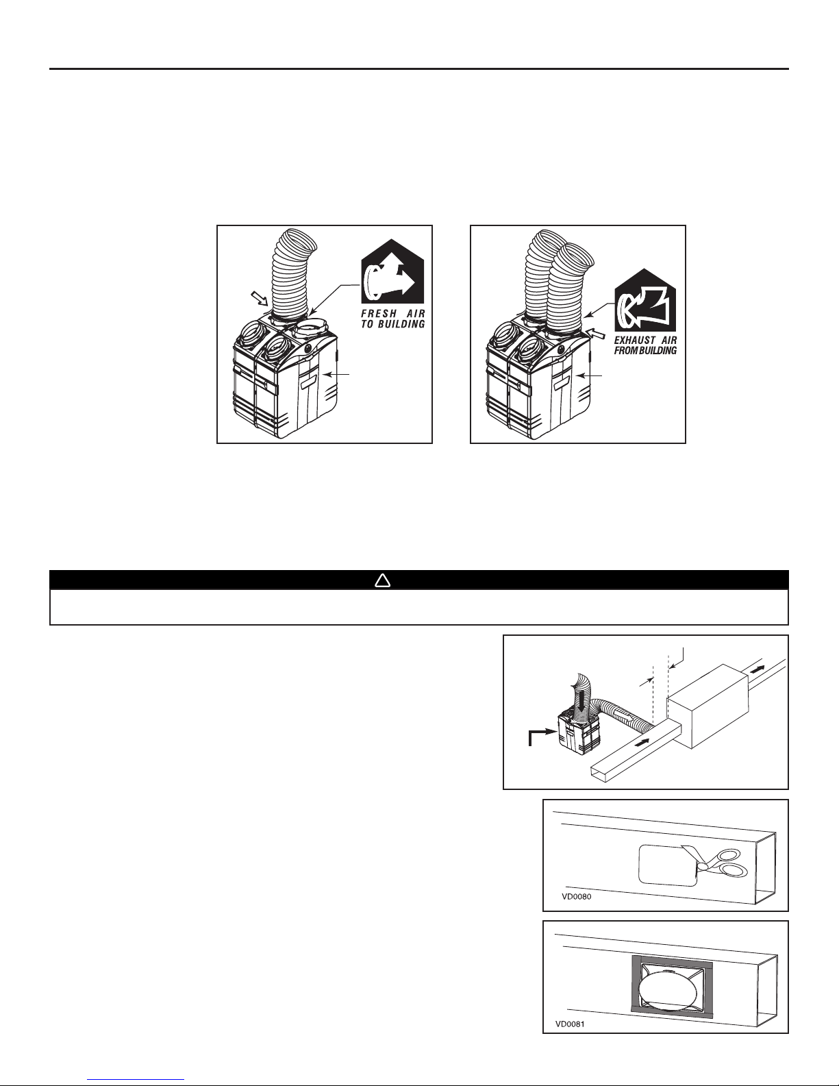
• Each port is identified on top of the unit (See illustrations below). Using the provided colored sticker dot, identify which duct it is
(red dot for stale airflow and blue dot for filtered airflow). Repeat the procedure for the other register.
• Attach the fresh air to building duct (the one with the blue dot) to its corresponding port, using tie wrap (1). Then, attach the exhaust
air from building duct (the one with the red dot) to the other 8’’ port (2).
NOTE: Use 8’’ insulated duct only (not included) when ductwork may go where ambient temperature is over or below comfort zone.
6.5.2 CENTRAL DRAW POINT (AS ILLUSTRATED IN SECTION 5.4)
Stale air ductwork
Same as for Stand Alone System, described in point 6.5.1.
Filtered air ductwork (Return side connection)
VJ0026A
Front door
of the unit
VJ0027A
Front door
of the unit
12
WARNING
When performing duct connections, always use approved tools and materials. Respect all corresponding laws and/or safety
regulations. Please refer to your local building code. Use only UL listed duct tape.
!
VD0128A
2 ft minimum
SUPPLY
RETURN
Front door
of the unit
• Using a metal shear or a hammer and a flat blade screwdriver, punch a hole into the
furnace / air handler return duct. Then, using metal shear, cut out the rectangular
hole.
• Mount the duct connector to the furnace / air handler duct using the provided four
retaining screws (no. 8 x 3/4”). Seal with UL approved duct tape.
- 17 -
Page 18
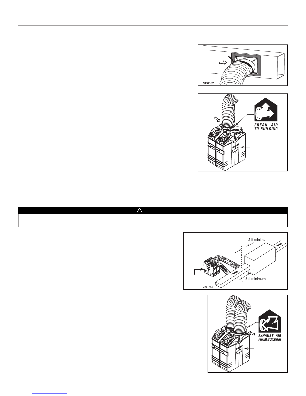
• Attach this duct to the
EXHAUST AIR FROM BUILDING
port (see icon on the top of the unit)
using tie wrap and duct tape.
6.5 INSTALLING 8’’ DUCTS AND REGISTERS (CONT’D)
6.5.2 C
ENTRAL DRAW POINT (AS ILLUSTRATED IN SECTION 5.4) (CONT’D)
• Take one end of the 8’’ flexible duct and slide it over the duct connector. Secure with
a tie wrap. Carefully seal the connection with UL approved duct tape. Identify the
duct using the blue sticker dot included.
• Attach this duct to the
FRESH AIR TO BUILDING
port (see icon on the top of the unit)
using tie wrap and duct tape.
6.5.3 RETURN-TO-RETURN (AS ILLUSTRATED IN SECTION 5.5)
Filtered air ductwork (Return side connection)
Same as for Central Draw Point, described in point 6.5.2.
Stale air ductwork (Return side connection)
• Locate the return air inlet duct at least 2’ (0.61 m) upstream (return side) from
furnace / air handler. Locate the take-off duct opening at least 3’ (0.9m) from
the filtered air ductwork connection. Proceed as for the filtered air ductwork,
but instead of using the blue dot sticker to identify the duct, use the red dot.
6. INSTALL THE UNIT (CONT’D)
- 18 -
VJ0026A
Front door
of the unit
WARNING
When performing duct connections, always use approved tools and materials. Respect all corresponding laws and/or safety
regulations. Please refer to your local building code. Use only UL listed duct tape.
!
Minimum 3’
(0.9 m) from
filtered air
ductwork
connection
SUPPLY
RETURN
Front door
of the unit
VJ0027A
Front door
of the unit
Page 19
6. INSTALL THE UNIT (CONT’D)
6.6 INSTALLING INSULATED FLEXIBLE DUCTS TO TANDEM®TRANSITION (GSVH1K, GSHH3K & GSEH3K MODELS ONLY)
Use the following procedure for connecting the insulated flexible ducts to the Tandem®transition* (
EXHAUST AIR TO OUTSIDE
and
FRESH AIR FROM OUTSIDE
).
*Patent pending.
NOTES: 1. If the joists are perpendicular to the ducts, or if the connection to the exterior hood is in a limited area, your installation will
need two exterior hoods instead of one AirDuo™ exterior hood. In this case, do not use the Tandem®transition.
2. If there is not sufficient space to install the Tandem®transition, both optional single exterior hood and AirDuo™ exterior hood
must be used. Identify each insulated duct. For fresh air from outside duct, use the blue sticker dots (one dot at each end).
For exhaust air to outside duct, use the red sticker dots (one dot at each end).
Then, go to Section 6.8 and 6.9.
6.6.1 CONNECTION TO TANDEM
®
TRANSITION
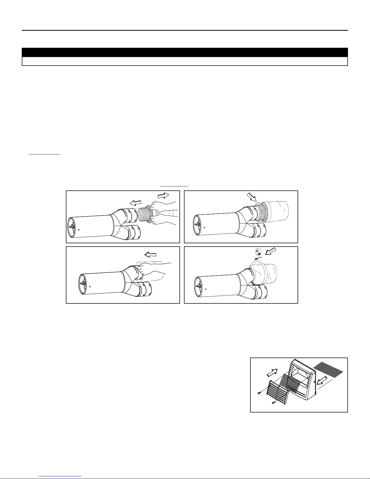
1. For each duct, pull back the insulation to expose the interior flexible duct.
2. Connect the interior flexible duct to the smaller part of the Tandem® transition (5’’ oval) using a 24’’ tie wrap.
NOTE: If you are using a 6’’ diameter insulated duct, use the bigger part of the Tandem® transition (6’’ oval).
3. Pull the insulation over the joint. Pull the vapor barrier over the insulation.
4. Apply duct tape gently to the joint in order to make an airtight seal
. See figures below.
Identify each insulated duct. For fresh air from outside duct, use the blue sticker dots (one dot at each end). For exhaust air to outside
duct, use the red sticker dots (one dot at each end). Be careful to identify the exhaust air to outside duct (red dot) at the upper
section of the transition.
6.7 INSTALLING AIRDUO™ EXTERIOR HOOD* (GSVH1K, GSHH3K AND GSEH3K MODELS ONLY)
6.7.1. ASSEMBLING AIRDUO™ EXTERIOR HOOD
AirDuo™ exterior hood requires assembly. Assemble the top metal screen, the plastic grille
and the bottom metal screen to AirDuo™ exterior hood. Use provided screws. See illustration
beside.
*Patent pending
- 19 -
CAUTION
Make sure the insulated ductwork vapor barrier does not tear during installation.
VJ0025
VJ0022
VJ0023
VJ0024
1
2
3
4
EXHAUST AIR TO OUTSIDE DUCT
ON TOP
VO0024
Page 20
6. INSTALL THE UNIT (CONT’D)
6.7 INSTALLING AIRDUO™ EXTERIOR HOOD* (GSVH1K, GSHH3K AND GSEH3K MODELS ONLY) (CONT’D)
6.7.2 L
OCATING THE AIRDUO™ EXTERIOR HOOD
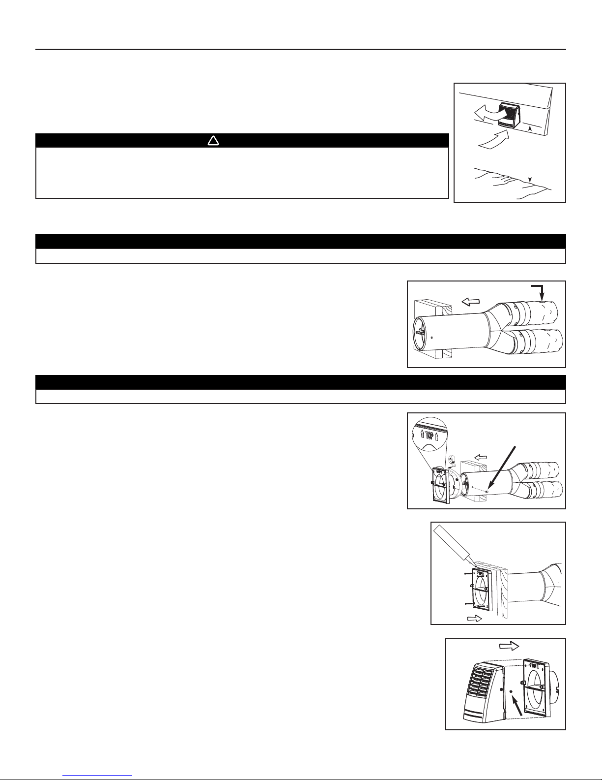
The AirDuo™ exterior hood must be installed at a minimum distance of 18 inches (457 mm) above the
ground. See illustration beside.
6.7.3 CONNECTING TANDEM® TRANSITION TO AIRDUO™ EXTERIOR HOOD
1. Using a jig saw, cut a 6’’ diameter hole in the exterior wall and insert the Tandem®
transition through this hole.
2. Joint the end of the Tandem® transition to the rear of the exterior backplate. Secure
with 2 Xmas tree pins and seal properly with duct tape.
VD0083A
18”
(457 mm)
WARNING
Make sure this hood is at least 6 feet (1.8 m) away (or more, as per applicable building codes or
standards) from sources of contamination such as:
• High efficiency furnace vent. •Any exhaust from a combustion source.
• Gas meter exhaust, gas barbecue-grill. •Garbage bin.
!
- 20 -
CAUTION
The exterior backplate must be installed with the word “TOP” pointing upward.
CAUTION
The Tandem® transition must be inserted in such a way that the
EXHAUST AIR TO OUTSIDE
duct will be located on the top.
VD0084
VD0085
Xmas tree pin
EXHAUST AIR TO OUTSIDE duct
3. Using 4 no. 8 x 1½” screws, attach the exterior backplate to the exterior wall. Seal the
outline with caulking, as shown.
VD0086
VD0087
screw
4. Snap the assembled AirDuo™ exterior hood on its backplate and secure with two
provided screws (no. 8 x 3/4” long). Go to Section 6.9.
Page 21
6.7 INSTALLING AIRDUO™ EXTERIOR HOOD* (GSVH1K, GSHH3K AND GSEH3K MODELS ONLY) (CONT’D)
6.7.4 O
PTIONAL ALPINE/PINE FILTER
The special design of this filter makes it much more efficient to catch spores and their particles during
intensive pollen season. Using this optional fine mesh filter will extend the life expectancy of your prefilter.
To install it, remove the bottom metal screen of the AirDuo™ exterior hood and replace it by the optional
Alpine/pine filter. See illustration beside.
(Alpine/pine filter part number: ACCGSUP5)
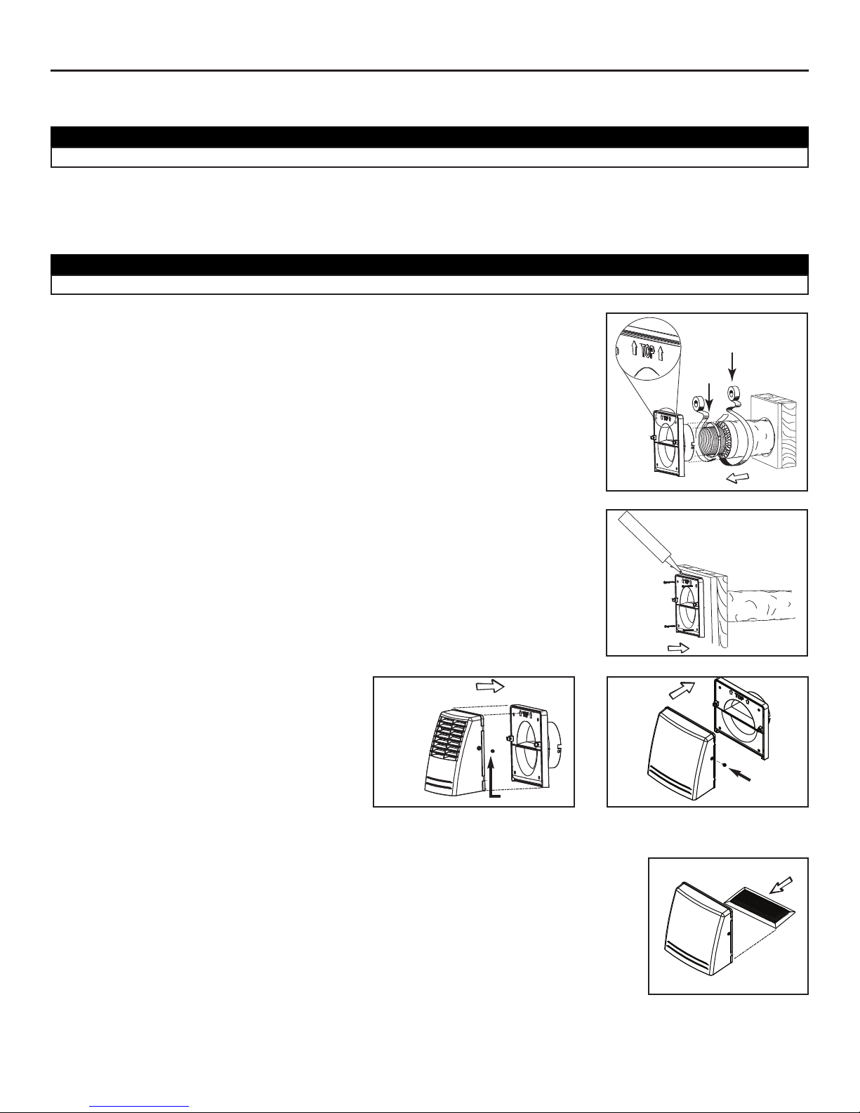
During pollen season, or as needed, remove the asembled hood from its backplate by removing its 2 retaining screws. Then, slide out
the Alpine/pine filter and clean it under water. Let dry before reinstalling it on the assembled hood. Reinstall the hood on its backplate.
6.8 INSTALLING TWO EXTERIOR HOODS* (GSVH1K, GSHH3K AND GSEH3K MODELS ONLY)
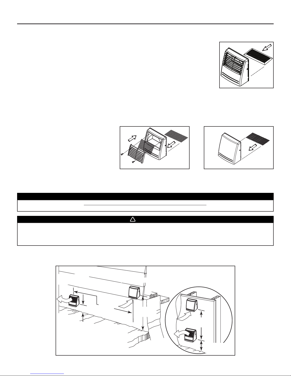
6.8.1 ASSEMBLING EXTERIOR HOODS
Both exterior AirDuo™ hood and optional exterior
single hood require assembly. Assemble the top
metal screen, the plastic grille and the bottom metal
screen to the AirDuo™ exterior hood*. Use provided
screws. Slide the bottom metal screen into the single
exterior hood base. See illustrations beside.
*Patent pending
6.8.2 LOCATING THE AIRDUO™ AND OPTIONAL EXTERIOR SINGLE HOOD
6. INSTALL THE UNIT (CONT’D)
- 21 -
VA0024
VO0030
VO0024
AirDuo™ EXTERIOR HOOD
OPTIONAL SINGLE FRESH AIR INLET
EXTERIOR HOOD
WARNING
Make sure the optional exterior single hood is at least 6 feet (1.8 m) away (or more, as per applicable building codes or standards)
from sources of contamination such as:
• High efficiency furnace vent. • Any exhaust from a combustion source.
• Gas meter exhaust, gas barbecue-grill. • Garbage bin.
!
CAUTION
Due to its particular design, the AirDuo™ exterior hood must be used only for exhaust hood when performing an installation
using 2 exterior hoods. Use the optional single fresh air intake exterior hood for supply air.
VD0094
4’’
(102 mm)
18’’
(457 mm)
4’’
(102 mm)
6’
(1.8 m)
Intake hood
Optional location
AirDuo™
Exhaust hood
6’
(1.8 m)
The AirDuo™ exterior hood must be installed at a minimum distance of 4 inches (102 mm) from the ground, and the optional single fresh
air intake exterior hood must be installed at a minimum distance of 18 inches (457 mm) from the ground. Also, a minimum distance of
6 feet (1.8 m) is required between the hoods to avoid cross-contamination. See illustration below.
Page 22
6.8 INSTALLING TWO EXTERIOR HOODS* (GSVH1K, GSHH3K AND GSEH3K MODELS ONLY) (CONT’D)
6.8.3 C
ONNECTING INSULATED DUCTS TO EXTERIOR HOODS
1. For each exterior hood, using a jigsaw, cut a 6’’ diameter hole (if using 5’’ dia. insulated duct) or a 7’’ diameter hole (if using 6’’ dia.
insulated duct) in the exterior wall. Identify each insulated duct. For fresh air from outside duct, use the blue sticker dots (one at
each end). For exhaust to outside duct, use the red sticker dots (one dot at each end). Run each flexible duct through its respective hole
in the wall.
2. Pull back the insulation to expose the flexible duct and, using a tie wrap, attach it to the inner
ring of the exterior backplate (5’’ ring for the 5’’ insulated ducts or 6’’ ring for the 6’’ insulated
ducts). Carefully seal with duct tape (A). Pull the insulation over the joint. Pull the vapor barrier
over the insulation and over the outer ring of the exterior backplate. Apply gently duct tape to
the joint making an airtight seal (B).
6. INSTALL THE UNIT (CONT’D)
CAUTION
Make sure the insulated ductwork vapor barrier does not tear during installation.
- 22 -
CAUTION
The exterior backplate must be installed with the word “TOP” pointing upward.
A
B
VD0095
3. Attach the exterior backplate to the exterior wall. Using four provided screws, fix it to the wall.
Seal the backplate with caulking, as shown.
VD0096
4. Snap each assembled exterior hood on its respective
backplate location and secure each of them with
their 2 provided screws.
VD0087
VD0097
AIRDUO™ EXTERIOR HOOD SINGLE EXTERIOR FRESH AIR INTAKE HOOD
screw
screw
6.8.4 OPTIONAL ALPINE/PINE FILTER
The special design of this filter makes it much more efficient to catch spores and their particles during
intensive pollen season. Using this optional fine mesh filter will extend the life expectancy of your prefilter.
To install it, remove the bottom metal screen of the optional exterior single hood and replace it by the
optional Alpine/pine filter. See illustration beside.
(Alpine/pine filter part number: ACCGSUP5)
During pollen season, or as needed, remove the assembled hood from its backplate by removing its 2 retaining screws. Then, slide out
the Alpine/pine filter and clean it under water. Let dry before reinstalling it on the assembled hood. Reinstall the hood on its backplate.
NOTE: Roof top venting is not recommended.
VA0025
Page 23

6.9 CONNECTION TO THE 5’’ TO 6’’ OVAL PORTS OF THE UNIT (GSVH1K, GSHH3K AND GSEH3K MODELS ONLY)
Use the following procedure for connecting the insulated flexible ducts to the 5’’ to 6’’ oval ports of the unit (
EXHAUST AIR TO OUTSIDE
and
FRESH AIR FROM OUTSIDE
).
1. Pull back the insulation to expose the flexible duct.
2. Connect the interior flexible duct to the smaller part of the port (5’’ oval) using a
24’’ tie wrap.
NOTE: If you are using a 6’’ diameter insulated duct, use the bigger part of the
port (6’’ oval).
6. INSTALL THE UNIT (CONT’D)
VJ0016
Rear side
of the unit
VJ0017
Rear side
of the unit
- 23 -
3. Pull the insulation over the joint and tuck it between the inner and outer rings of the port.
Pull the vapor barrier over the insulation and over the outer ring of the port.
VJ0018
Rear side
of the unit
4. Apply duct tape gently to the joint in order to make an airtight seal.
VJ0019
Rear side
of the unit
5. Repeat steps 1 to 4 for all insulated ducts.
See figure beside to find the
EXHAUST AIR TO OUTSIDE
(1)
and
FRESH AIR FROM OUTSIDE
(2) oval ports on the top of the unit.
Be careful to connect the right insulated duct to its corresponding port.
1) Red dot duct
2) Blue dot duct
Rear side
of the unit
VJ0028A
1
2
CAUTION
Avoid compressing the insulation when you pull the tape tightly around the joint. Compressed insulation loses its insulation
properties and causes water dripping due to condensation on the exterior surface of the duct.
Page 24

6. INSTALL THE UNIT (CONT’D)
- 24 -
6.10 CONNECTING THE DRAIN (GSHH3K MODEL ONLY)
VO0025
1
VO0046
1
2
3
1. Open the door by turning the switch
knob to the OFF position (to unlock
the door). Then, unlatch the door
and open it. Slide out the core
assembly to access the 2 drain fitting
hole locations (1). Punch out the
holes.
2. Hand tighten the 2 plastic drain
fittings (1) using the gaskets (2) and
nuts (3) as shown. Close the door.
12
VO0027
27''
(686 mm)
7''
(178 mm)
3. Cut 2 sections of plastic tubing; one
7’’ (178 mm) long and one 27’’ (686 mm)
long, and attach them to each drain
fitting as shown.
3
VO0028
4. Join these 2 sections to the ‘’T’’
junction and main tube as shown.
VO0029
4
5
Tie-wrap
Water
To drain
5. Make a water trap loop in the tube to
prevent the unit from drawing
unpleasant odors from the drain
source. Make sure this loop is situated
BELOW the ‘’T’’ as shown. This will
prevent water from being drawn back
up into the unit in case of negative
pressure. Run the tube to the floor
drain or an alternative drain pipe or
pail. Be sure there is a slight slope
for the run-off.
6.11 LOW TEMPERATURE APPLICATIONS BELOW FREEZING (32°F OR 0°C)
ALL MODELS
FOR GSHH3K HEAT RECOVERY AND GSEH3K ENERGY RECOVERY MODELS ONLY
GENERAL:
• Insulate the cabinet body using a 2” thick blanket insulation or by placing the unit in an insulated enclosure formed from 2” thick
fiberglass insulation board.
• Make sure that all ductwork is insulated.
• Carefully seal all of the unit ports with duct tape to prevent air leakage.
• Install a heating cable along the drain line for freeze protection.
- Use a UL listed heat tape in accordance to the manufacturer’s instruction.
- Because of the additional weight of the heating tape on drain line, secure the plastic tubing to each drain fitting using hose clamps
(not provided).
- Make sure the heat tape is rated between 3 to 6 watts per foot at 120 V.
- Protect the circuit the heat tape is connected to with a ground-fault circuit breaker.
- Cover the drain line and heating cable with 1/2 inch thick insulation.
- If you need to extend the drain line beyond the 9 foot length supplied with the unit, use copper pipe.
CAUTION
When the ambient temperature surrounding the unit falls below freezing (32°F or 0°C), all units must run continuously to
prevent condensation.
CAUTION
• When installing an GSHH3K HEPA Filtration, Fresh Air and Heat Recovery model, make sure the unit cabinet and its drain
line are protected from freezing.
• When installing an GSHH3K HEPA Filtration, Fresh Air and Heat Recovery model, install a drip pan if required by local code.
Page 25

6. INSTALL THE UNIT (CONT’D)
- 25 -
6.11 LOW TEMPERATURE APPLICATIONS BELOW FREEZING (32°F OR 0°C) (CONT’D)
6.11.1 B
LANKET INSULATION
If fabricating an insulation blanket, use a 2” thick hot
water heater blanket cut as shown.
Wrap the unit as shown. Make sure that all joints are fully sealed to prevent cold air penetration between the insulation and the unit.
NOTES: 1. Holes must be done in the insulation blanket
to allow drain line installation for model
GSHH3K only.
2. MAKE SURE to use excess insulation to
cover the top of unit and its ports.
75
48
24
27
27
19
5
8
20
1
8
17
1
2
17
1
2
23
3
4
58
3
4
Bend UP 90
0
Bend UP 90
0
Bend UP 90
0
Rectangular
Door
Insulation
T- Shaped
Cabinet
Insulation
Wrap
2
1
2
Cut slots
inches
24
VR0001A
VR0002
1 2
3
Heat
tape around
drain
VH0044
Attic
insulation
2” Thick
ductboard
Optional
drain
pan
Waste
drain
Insulated
ducts
Remove
some attic
insulation to
allow heat into
enclosure
from building
below
Heat
tape on
drain
line
Hose
clamp
Hose
clamp
CUT AWAY VIEW WITH THE DUCT BOARD ENCLOSURE DOOR REMOVED.
6.11.2 DUCT BOARD INSULATED ENCLOSURE
If fabricating an enclosure from 2” fiberglass duct board,
make sure that the enclosure is thightly sealed.
When possible have the waste disposal point within the
confines of the enclosure to expedite water removal (for
GSHH3K model only).
Page 26

7.1 MAIN SWITCH
All units are equipped with a 3-position main switch, located on the front panel. The unit is intented for use with a wall
controller (provided, see below). The main switch is to remain in either the “OFF” or “Normal/Remote” modes ONLY. The “Normal/Remote”
mode allows the homeowner to operate the product from the wall controller, typically mounted near a thermostat or other convenient
location.
7.2 WALL CONTROLLERS (ONE PROVIDED WITH THE UNIT)
There are two wall controllers available: ACCGSC1 control (intended for GSFH1K and GSVH1K models only) and 40425 control (intended
for GSHH3K and GSEH3K models only).
ACCGSC1 40425
CONTROLLER CONTROLLER
- 26 -
7. CONTROLS
OFF:
UNIT IS OFF AND
DOOR IS
UNLOCKED
.
BOOST:
UNIT IS OPERATING
ON HIGH SPEED.
VC0059
High
Low
OFF
Reset Filter
Filter Maintenance
Power
VC0098
VC0053
NORMAL/REMOTE:
UNITISOPERATINGON
LOW SPEED. THIS IS THE
RIGHT POSITION WHEN
AN OPTIONAL WALL
CONTROL IS USED
.
Page 27

7.3 INSTALLATION OF THE ACCGSC1 WALL CONTROLLER
1. Determine the more convenient location for the control.
2. Remove the controller cover plate (1). If you prefer to have your main control mounted on an
approved outlet box or an approved mounting bracket (not included), discard the backplate (2).
3. Route the control cable from the unit to the wall controller.
Use the provided cable (4-conductor, 24-gauge, Solid, UL Listed, CM type, 40’ long).
NOTE: For wall controller efficiency, the maximum wire length is 100’ (30.5 m). If needed, add another length of same wire type.
Use caution not to cross the wire colors or create any short.
4. Take one end of the provided cable and pass it through the wall control backplate (or outlet box or mounting bracket).
5. Splice back this end of the cable to access to the four wires. Remove the insulated
sleeve of each wire ends. Make a loop with each bare end wire to hook them to their
corresponding screw. Connect YELLOW wire to “Y’’ screw, RED wire to “R’’ screw,
GREEN to “G’’ screw and BLACK to “B’’ screw. See illustration beside.
6. Reinstall the cover plate. Using provided wall anchors and provided screws, mount the wall controller on the wall. Use only 2 screws
to mount on outlet box. See illustrations below. Once done, go to Section 7.5
Wall Controllers Connection to the Unit.
1) Wall anchors 4) Control 1) Outlet box 3) Control
2) Control cable 5) Screws 2) Control cable 4) Screws
3) Backplate
- 27 -
7. CONTROLS (CONT’D)
CAUTION
Never install more than one optional wall controller per unit.
WARNING
Always disconnect the unit before making any connections. Failure in disconnecting power could result in electrical shock or
damage of the wall control or electronic module inside the unit.
!
WARNING
To avoid risk of electrical shocks, never install another wire in the same electrical box than the one for the wall controller.
!
1
2
BLACK
wire
YELLOW
wire
GREEN
wire
RED
wire
WARNING
Make sure that the wires do not short circuit between themselves or by touching
any other components on the wall controller.
!
VC0052
VC0051
1
3
4
5
2
3
4
1
2
SURFACE MOUNT
RECESS MOUNT
CAUTION
Keep control low voltage wiring at least 1’ (305 mm) away from motors, lighting ballast, light dimming circuit and power
distribution panel. Do not route control wiring along house power wiring. Avoid poor wiring connections. Failure to follow
these practices can introduce electrical interference, which can cause erratic control operations.
Page 28

7. CONTROLS (CONT’D)
7.4 INSTALLATION OF THE 40425 WALL CONTROLLER
WARNING
Always disconnect the unit before making any connections. Failure in disconnecting power could result in electrical shock or
damage of the wall control or electronic module inside the unit.
!
CAUTION
Failure to comply with the following can cause erratic operation of the unit:
• Never install more than one optional wall controller per unit.
• Keep control low voltage wiring at least 1foot (305 mm) away from motors, lighting ballast, light dimming circuit
and power distribution panel. Do not route control wiring alongside house power wiring.
• Ensure the wires are securely connected.
• Disconnect power from the unit before removing the wall controller faceplate from its mounting plate.
1. Route the cable from the unit to a convenient location for the wall control.
2. Loosen the locking screw (the screw cannot be completely removed).
3. Detach the faceplate from the mounting plate by pulling the bottom part. If necessary, bore the mounting
holes and insert anchors.
4. Pass the cable (4 wires) through the opening of the mounting plate and mount the plate to the wall using
the provided screws.
5. Splice back the end of the cable to access to the 4 wires. Strip the end of each wire. Connect each wire
to its corresponding terminal: YELLOW wire to “Y’’, RED wire to “R’’, GREEN to “G’’ and BLACK to “B’’.
See illustration beside.
6. Reinstall the front module onto the back plate and tighten the locking screw.
VC0095
VC0096
VC0097
VE0157
BLACK
wire
YELLOW
wire
GREEN
wire
RED
wire
- 28 -
Page 29

7.5 WALL CONTROLLERS CONNECTION TO THE UNIT (BOTH MODELS)
1. Go to the unit. Turn the unit switch knob to OFF position in order to unlock the door. Unlatch the
door and open it. If required, the door can be removed. To do so, remove the stopper (A) located
on the right side of the door hinge. Then, hold the door and hit with your palm its left side. Slide
the door to the right to disengage it from the unit.
2. Using a screwdriver, remove both front plate retaining screws and carefully remove the front
plate of the unit.
3. Using a small rod, pierce a hole through the unit at the end of the wire channel. (See
photo beside). Splice back the end of the cable to access the 4 wires. Remove the insulated
sleeve of each wire ends. Insert the end of the cable through the unit, using the small
hole previously done. From the top right hole of the unit, pull on the wire.
4. In order to access the unit PCB terminals, remove the side door located on the electrical
box and punch out its knockout. Run the cable through the knock-out hole and connect
each wire in their corresponding terminal (YELLOW in “Y’’, RED in “R’’, GREEN in “G’’
and BLACK in “B’’).
NOTE: Push forward slightly on the little tabs (1) to ease insertion of each wire.
See photo beside.
5. Reinstall the side door on the electrical box and install the 8’’ oval port on the unit.
6. Route the wire through its channel and reinstall the front panel on the unit.
See picture beside.
7. Plug the unit to the wall outlet.
NOTE: When using the wall controller, the main switch on the unit must always be positioned to NORMAL/REMOTE.
7. CONTROLS (CONT’D)
VO0019
VD0088
CAUTION
Never use a drill to pierce the hole through the unit, since electrical component
inside the unit may be damaged.
VE0049
1
VD0170
A
VD0089
- 29 -
Page 30

7. CONTROLS (CONT’D)
7.6 OPERATING ACCGSC1 CONTROLLER
7.6.1 ACCGSC1 C
ONTROLLER DESCRIPTION
7.6.2 USING ACCGSC1 CONTROLLER
• OFF: To stop the unit, slide the button on this position.
• LOW: For a day-to-day usage, slide the button on this position.
The unit then will operate on low speed, providing 70 cfm.
• HIGH: For a high speed operation, slide the button on this position.
Generally used when more ventilation is required, such as parties, smokers, or for a 6-bedroom house.
This mode provides 105 cfm.
VC0059
High
Low
OFF
Reset Filter
Filter Maintenance
Power
OFF:
UNIT IS OFF.
POWER INDICATOR:
LIGHTS UP WHEN SLIDE SWITCH
IS ON LOW OR HIGH POSITION.
FILTER MAINTENANCE
INDICATOR
:
FLASHES EVERY MINUTE TO
INDICATE IT IS ON DUTY.
FLASHES EVERY SECOND WHEN
ITS TIME TO REPLACE
PREFILTER
. SEE SEMI-ANNUAL
MAINTENANCE IN SECTION 9.2.
LED STAYS LIT WHEN ITS TIME TO
REPLACE FILTER AND PREFILTER.
Low:
U
NITISOPERATINGON
LOW SPEED.
RESET FILTER HOLE:
ONCE THE MAINTENANCE DONE, RESET THE FILTER
MAINTENANCE INDICATOR BY CAREFULLY INSERTING
ASMALLROD
(EG: PAPER CLIP) IN THE RESET FILTER
HOLE, FOR 1 SECOND. THE FILTER MAINTENANCE
INDICATOR WILL TURN OFF. REFER TO THE FILTER
MAINTENANCE RECOMMENDATIONS IN SECTION 9.
HIGH:
U
NITISOPERATINGON
HIGH SPEED
.
- 30 -
7.7 OPERATING 40425 CONTROLLER
7.7.1 ACCGSC3 C
ONTROLLER DESCRIPTION
This wall controller is in OFF mode when power is applied for the first time. The mode does not change following a power failure.
VC0098
ILLUMINATES IN ALL MODES
EXCEPT OFF MODE.
FILTER AND PREFILTER MAINTENANCE LED.
FLASHES WHEN IT IS TIME TO REPLACE
PREFILTER AND WASH CORE FILTERS
.
SEE BIANNUAL MAINTENANCE IN SECTION 9.1.
LIGHTS UP WHEN IT IS TIME TO REPLACE
FILTER AND PREFILTER AND WASH CORE FILTERS
.
SEE ANNUAL MAINTENANCE SECTION 9.2.
PRESS THIS BUTTON TO
ACCESS CONFIGURATION PARAMETERS
(SEE SECTION 7.7.3).
•PRESS EITHER BUTTON TO CHANGE
CONFIGURATION SETTING
(SEE SECTION 7.7.3).
•P
RESS BOTH BUTTONS TO RESET THE FILTER
COUNTER OR PREFILTER COUNTER
.
PRESS THIS BUTTON TO
SWITCH MODE
(SEE SECTION 7.7.2).
Page 31

7. CONTROLS (CONT’D)
7.7 OPERATING 40425 CONTROLLER (CONT’D)
7.7.2 OPERATING 40425 CONTROLLER
The wall controls 40415 and 40425 provide 5 operation modes. Press the Mode button to select the desired mode.
The unit exchanges air
at normal speed.
The outdoor
temperature* is displayed.
The unit exchanges air
at high speed.
The outdoor
temperature* is displayed.
The unit recirculates air. However,
every hour, the unit exchanges
air for 6 minutes so that
it can obtain a reading
of the outdoor temperature*.
The unit operates on a 60-minute cycle.
For the first 40 minutes, the unit recirculates
air or is off (See configuration parameter 2).
For the last 20 minutes, it exchanges air.
However, if the outdoor temperature* is too
high or too low (see configuration
parameters 3 and 4), the unit recirculates
air during the last 20 minutes.
N
ORMAL MODE (MIN)BOOST MODE (MAX)RECIRCULATION MODE (RE-CIRC)OFF MODE
The unit is off.
The outdoor temperature*
is not displayed.
Off in
Auto mode
Air exchange in
Auto mode
Air recirculation
in Auto mode
AUTOMATIC MODE (AUTO)
* The outdoor temperature reading is taken from the unit
FRESH AIR
FROM OUTSIDE
port; due to the lenght of the insulated duct, the reading
is slightly different from the real outside temperature.
MENU
PARAMETER OPTIONS
DEFAULT
DESCRIPTION
NUMBER SETTING
1TEMPERATURE FORMAT °C / °F °C SELECTS BETWEEN °C AND °F DISPLAY.
2A
UTO MODE OPERATION RE / OF RE
S
ELECTS BETWEEN AIR RECIRCULATION (RE) AND OFF (OF)
(SEE SECTION 7.7.2).
3
AUTO MODE LOW -30°C TO 0°C -25°C PREVENTS AIR EXCHANGE IN AUTO MODE IF THE OUTDOOR
TEMPERATURE LIMIT (-22°F TO 32°F) (-13°F) TEMPERATURE IS TOO LOW (SEE SECTION 7.7.2).
4
AUTO MODE HIGH 0°C TO 30°C 27°C PREVENTS AIR EXCHANGE IN AUTO MODE IF THE OUTDOOR
TEMPERATURE LIMIT
(32°F TO 86°F) (81°F) TEMPERATURE IS TOO HIGH (SEE SECTION 7.7.2).
AU: THE SCREEN ILLUMINATES FOR 12 SECONDS WHEN ANY
5BACKLIGHT MODE AU / ON AU KEY IS PRESSED
ON: THE SCREEN IS PERMANENTLY ILLUMINATED.
7.7.3 40425 WALL CONTROLLER CONFIGURATION
See the configuration table below for the list of configuration parameters.
Press the Menu button for 3 seconds to enter or exit the configuration menu.
NOTE: The wall control automatically saves any changes and exits the configuration menu if no button is pressed within the
next 60 seconds.
Press the Menu button briefly to advance to the next parameter (menu number).
Press the or button to change the parameters setting.
CONFIGURATION TABLE
- 31 -
Page 32

- 32 -
8. BALANCING PROCEDURE (GSVH1K, GSHH3K AND GSEH3K UNITS ONLY)
8.1 WHAT YOU NEED TO BALANCE THE UNIT
• A magnehelic gauge capable of measuring 0 to 0.5 inches water gauge (0 to 125 Pa)
and 2 plastic tubes.
• Two flow collars (the size will vary depending of duct diameter).
VP0005
Flow collar
8.2 PRELIMINARY STAGES FOR BALANCING THE UNIT
Seal all the unit ductwork with tape. Close all windows and doors. Turn off all exhaust devices such as: range hoods, dryers and
bathroom fans. Make sure balancing dampers are fully open
(F and G in figure below).
Choose an appropriate location for the 2 flow collars according to figure below:
• On the exhaust air duct (first measuring location, A)
• On the fresh/filtered air distribution duct (second measuring location, B)
• At least 36” (914 mm) away from the unit; at least 12” (304 mm) before or after 90° elbow and at least 12” (304 mm) away from a register.
• At least 12” (304 mm) away a from a balancing damper (F and G in figure below).
12¨(304mm)
12¨(304mm)
36¨(914mm)
36¨(914mm)
OR
B
A
F
G
VP0014A
12¨(304mm)
12¨(304mm)
Insert the flow collars in the ducts at each location (A et B on figure above). Make sure their arrows are pointing in the direction of the
airflow. Tape collars in place temporarily.
8.3 INSTALLATION OF FLOW COLLAR
8.4 BALANCING PROCEDURE
1. Set the unit to high speed.
Make sure that the furnace blower is ON if the installation is in any way connected to the ductwork of the cold air return. If not leave
furnace blower OFF.
2. Place the magnehelic gauge on a level surface and adjust it to zero.
3. Connect tubing from gauge to flow collar in exhaust air stream (location A in illustration above). Be
sure to connect the tubes to their appropriate high / low fitting. If the gauge reading drops to below
zero, reverse the tubing connections.
NOTE: It is better to start with the exhaust air flow reading because the exhaust typically has more
restriction than the fresh air, especially in cases of stand alone and central draw point installations.
Hold or place the magnehelic gauge upright and level. Record the reading.
4. Move tubing to the other side of the unit (location B in illustration above and note reading. Adjust the fresh
air balancing damper F until the reading at B is approximately the same as the reading at A. If the reading
at B is less than the reading at A then go back and adjust the exhaust balancing damper G to equal the
fresh air flow.
5. Remove flow collars and reconnect the duct, then, seal with duct tape. Write the required airflow information on a label and stick it
near the unit for future reference: (date, maximum speed airflows, your name and phone number and business address).
NOTES: 1. Most flow collar kits provide a conversion chart situated on the collar which enables you to convert magnehelic gauge readings
to equivalent cfm values.
2. A difference of ± 10 cfm ( ± 0.015 inches water gauge) between the 2 readings is considered balanced.
3. If you are using only one flow collar, then, after completing the first reading, transfer this measuring device to the other side
of the unit and take the second reading.
LOW
HIGH
FLOW
VP0003
LOW
HIGH
FLOW
VP0004
All units are prebalanced. However, if your construction code requires to balance the unit, follow this procedure.
FRONT DOOR
Page 33

9. MAINTENANCE
WARNING
Risk of electrical shocks. Before performing any maintenance or servicing, always disconnect the unit from its power source.
!
- 33 -
9.1 SEMI-ANNUAL MAINTENANCE (ESSENTIAL)
Your wall controller (ACCGSC1 or 40425) tells you when to perform this maintenance when the Filter Maintenance light is flashing.
Otherwise, maintenance should be performed every 6 months to ensure your unit proper operation for years to come. Follow these steps:
1. Turn switch knob to OFF to unlock the door.
2. Unlatch the door and open it. If required, the door can be removed. To do so, remove the
stopper (A) located on the right side of the door hinge. Then, hold the door and hit with your
palm its left side. Slide the door to the right to disengage it from the unit. Clean the inner side
of the door with a clean damp cloth, then wipe with a dry one.
3. Slide out the air diffuser (model GSVH1K), the heat recovery module (model GSHH3K only), the energy recovery module (model
GSEH3K only) and the filter cartridge from the unit.
NOTES: 1. On model GSVH1K only, never grab the white shaft (item 2) to pull out the air diffuser.
2. To remove the filter cartridge, pull on its tabs.
1) Air Diffuser 3) Heat recovery core 4) Energy recovery core 5) Filter cartridge tabs
2) White shaft
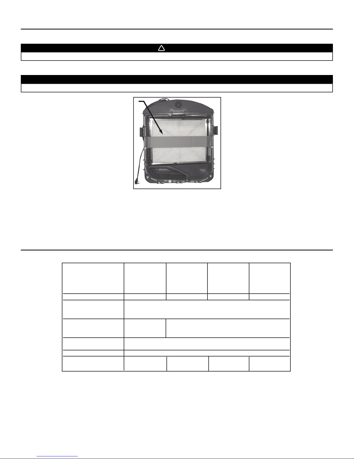
4. Using your thumbs, push on the prefilter side to disengage it from the filter cartridge. Then, slide it out of the filter cartridge and discard
it. Install the new prefilter by reversing this operation.
1) Filter cartridge
2) Prefilter
5. Clean the inside walls of the unit with a clean damp cloth, then wipe with a dry one. Reinstall the filter cartridge.
6.1 For HEPA Filtration and Fresh Air Ventilation model GSVH1K only
Clean the air diffuser with a clean damp cloth, then wipe with a dry one. Once the air diffuser completely dry, slide it back into the unit.
1
3
4
VD0107
VD0091
VD0112
5
VD0155
2
1
2
VD0092
VD0093
VD0170
A
Page 34

9.1 SEMI-ANNUAL MAINTENANCE (ESSENTIAL) (CONT’D)
6.2 For HEPA Filtration, Fresh Air and Heat Recovery model GSHH3K only
Slide out the two core filters (item 1) from the heat recovery core and wash them under hot
water with mild soap.
Remove the dust on the heat recovery core (item 2) using a vacuum cleaner with a soft brush
attachment.
Rinse the core filters thoroughly and let dry before reinstalling them on the heat
recovery core.
Reinstall the heat recovery core in the unit.
1) Core filters
2) Heat Recovery Core
NOTE: Make sure the damper spring (1) is still inside the left front port opening before
reinstalling the heat recovery module.
1) Damper spring
6.3 For HEPA Filtration, Fresh Air and Energy Recovery model GSEH3K only
Slide out the two core filters (item 1) from the energy recovery core and wash them under hot water
with mild soap.
Remove the dust on the energy recovery core (item 2) using a vacuum cleaner with a soft brush
attachment.
Rinse the core filters thoroughly and let dry before reinstalling them on the energy recovery
core.
Reinstall the energy recovery core in the unit.
1) Core filters
2) Energy Recovery Core
NOTE: Make sure the damper spring (1) is still inside the left front port opening before
reinstalling the energy recovery module.
1) Damper spring
7. If removed, reinstall the door. Close the latches and turn ON the switch knob to its previous position.
8. Your unit is equipped with a wall controller (ACCGSC1 or 40425). For ACCGSC1, reset the filter maintenance indicator by inserting a
small rod (eg: paper clip end) into the reset filter hole of the wall control. Press lightly until the Filter Maintenance indicator light
turns off. For 40425, to reset the counter and turn the LED off, simultaneoustly press both and buttons for 1 second.
9. MAINTENANCE (CONT’D)
VD0120
1
VD0120
1
VD0091
1
1
2
CAUTION
The energy recovery core cannot be washed with water.
1
1
2
VD0155
- 34 -
Page 35

9.2 ANNUAL MAINTENANCE (ESSENTIAL)
Your unit is equipped with a wall controller (ACCGSC1 or 40425), which tells when to perform maintenance when the Filter Maintenance
light stays ON. Otherwise, this maintenance must be performed once a year to ensure your unit proper operation for years to come.
Proceed as the Semi-annual Maintenance (Section 9.1), but instead of replacing the prefilter (point 4), discard the complete HEPA Filter
cartridge (including prefilter). Install a new HEPA filter cartridge with a new prefilter on it.
NOTE: In annual maintenance, for 40425 wall controller, press simultaneoustly both and buttons for 5 seconds to reset the counter
and turn the LED off.
9. MAINTENANCE (CONT’D)
- 35 -
9.3 OPTIONAL ALPINE/PINE FILTER (PART NUMBER: ACCGSUP5)
During pollen season, or as needed, remove the assembled hood from its backplate by removing its
2 retaining screws.
Then, slide out the optional Alpine/pine filter and clean it under water. Let dry before reinstalling it on the
assembled hood. Reinstall the hood on its backplate.
VA0024
VD0124
screw
PROBLEMS SOLUTIONS
1.Unit does not start at Low • Check breaker or fuse in main distribution panel or GFI outlet.
or High position. • Check there is 120V at the electrical outlet.
• Make sure the unit main switch is properly set in Normal or Boost position.
• If a wall control (ACCGSC1 or 40425) is connected, disconnect control wire from the
unit, then make sure the unit main switch is properly set in Normal/Remote or Boost
position.
• Check the fuse on electronic board. If blown, replace with the same type.
2.Unit does not run at Low • If a wall control (ACCGSC1 or 40425) is used, disconnect control wire from the unit.
speed, but runs at High. Then, if the unit runs at Normal speed, check control wiring and wall control connections.
3.Unit is not operating as per • Check if the unit main switch is in “Normal/Remote” position.
the selected mode. • Check wall control wiring.
4.Wall control indicators do not work
• Check wall control wiring.
properly or not at all.
5.On 40425 wall controller only, 1 or 2 • Check if the unit main switch is in “Normal/Remote” position.
light indicators are flashing every second. • Check wall control wiring.
6.On 40425 wall controller only,
• Check wall controller wiring.
wall controller screen indicates E1.
7.On 40425 wall controller only, • The temperature sensor is defective. (The unit will automatically switch to OFF mode
wall controller screen indicates E2. if this happens.)
10.TROUBLESHOOTING
If the problem is still not solved, call your installer or the nearest approved Service Center.
Also, you can reach the Customer Service Departments or Technical Supports listed below.
Broan-NuTone LLC
• Customer Service Department:
Telephone: 1-800-558-1711
Fax: 1-800-356-5862
• Technical Support:
Telephone: 1-800-637-1453
Fax: 1-262-673-8709
Page 36

11. WARRANTY
WARRANTY
Broan-NuTone warrants to the original consumer purchaser of its products, that such products will be free from defects for a period of
two (2) years, from date of original purchase.
THERE ARE NO OTHER WARRANTIES, EXPRESS OR IMPLIED, INCLUDING, BUT NOT LIMITED TO, IMPLIED WARRANTIES OF
MERCHANTABILITY OR FITNESS FOR A PARTICULAR PURPOSE. BROAN-NUTONE WILL NOT BE HELD RESPONSIBLE FOR
ANY CLAIMS OVER THE ORIGINAL PURCHASE PRICE OF A BROAN-NUTONE WHOLE-HOUSE AIR FILTRATION SYSTEM,
NOR HELD RESPONSIBLE FOR SUBSEQUENT DAMAGE OR INCIDENT.
During the period stated above, Broan-NuTone will, at its opinion, repair or replace, without charge, any product or part which is found
to be defective under normal use and service. THIS WARRANTY DOES NOT EXTEND TO ANY FILTER, PREFILTER OR CORE FILTERS
(IF APPLICABLE). This warranty does not cover a) normal maintenance and service, b) any products or parts which have been subject
to misuse, negligence, accident, improper maintenance or repairs made by other than Broan-NuTone or c) a faulty installation or
installation contrary to recommended installation instructions.
The duration of any implied warranty is limited to the 2-year period as specified for the express warranty. Some states do not allow
limitation on how long an implied warranty lasts, so the above limitation may not apply to you.
BROAN-NUTONE’S OBLIGATION TO REPAIR OR REPLACE AT BROAN-NUTONE’S OPTION, SHALL BE THE PURCHASER'S
SOLE AND EXCLUSIVE REMEDY UNDER THIS WARRANTY. BROAN-NUTONE SHALL NOT BE LIABLE FOR INCIDENTAL,
CONSEQUENTIAL OR SPECIAL DAMAGES ARISING OUT OF OR IN CONNECTION WITH PRODUCT USE OR PERFORMANCE.
SOME STATES DO NOT ALLOW THE EXCLUSION OR LIMITATION OF INCIDENTAL OR CONSEQUENTIAL DAMAGES, SO THE
ABOVE LIMITATION OR EXCLUSION MAY NOT APPLY TO YOU.
This warranty gives you specific legal rights and you may also have other rights, which vary from state to state. This warranty supersedes
all prior warranties.
In order to qualify for a warranty claim, the owner of a Broan-NuTone WHOLE-HOUSE AIR FILTRATION SYSTEM must have the
model and serial number along with a proof of the original purchase date. In each case, costs for the removal of a defective part (and/or
unit) and installation of a new or repaired one and travel costs are not covered by this warranty.
BROAN-NUTONE LLC, 926 W. S STATE ST, HARTFORD WI 53027 1-800-637-1453
WHOLE-HOUSE AIR FILTRATION SYSTEM
99043105
- 36 -
Page 37

VB0061
Filtración HEPA y
purificación
de aire*
GSVH1K
MANUAL DE INSTRUCCIONES
DE INSTALACIÓN
EXCLUSIVAMENTE PARA USO RESIDENCIAL.
INSTALADOR: ENTREGUE ESTE MANUAL AL CLIENTE.
Broan-NuTone LLC; Hartford, Wisconsin www.broan.com 800-558-1711
REGISTRE SU PRODUCTO EN LÍNEA EN: www.broan.com/register
Para obtener más información, visitar nuestro sitio www.broan.com
04326 rev. 7
99043105
*Patentes pendientes
Filtración HEPA,
purificación de aire
y recuperación de
calor*
GSHH3K
Filtración HEPA,
purificación de aire
y recuperación de
energía*
GSEH3K
Filtración
HEPA*
GSFH1K
LEA Y CONSERVE ESTAS INSTRUCCIONES
Page 38

ACERCA DE ESTE MANUAL
¡Felicitaciones! Su compra de este sistema de filtración HEPA para toda la casa con ventilación opcional le permitirá a usted y a su familia
disfrutar de un aire limpio y saludable en todo su hogar durante los próximos años.
Por favor, lea detenidamente este folleto.
En esta publicación se describen varios modelos. Algunos detalles de su unidad pueden ser ligeramente distintos de los que aparecen
aquí, ya que se han utilizado ilustraciones generales.
Este manual utiliza los símbolos siguientes para destacar determinada información:
NOTA: Indica información complementaria necesaria para cumplir perfectamente una instrucción.
Si lo desea, puede enviarnos cualquier sugerencia acerca de este manual o del producto, o bien puede indicarnos cómo cree que
podemos prestarle un mejor servicio. Por favor, remita su correspondencia a la dirección siguiente:
Broan-NuTone LLC
Indoor Air Quality Marketing
926 W. State St.,
Hartford, WI 53027
1-800-558-1711
ADVERTANCIA
Señala una instrucción que, de no seguirse, podría causar graves lesiones personales y, en algunos casos, incluso la muerte.
PRECAUCIÓN
Señala una instrucción que, de no seguirse, podría causar graves daños a la unidad o a sus componentes.
- 2 -
INFORMACIÓN SOBRE ESTAS UNIDADES
ADVERTANCIA
PRECAUCIÓN
1. Para uso de ventilación general exclusivamente. No utilice la unidad para extraer gases o materiales peligrosos o explosivos.
2. Destinado para uso residencial de acuerdo con los requisitos de la norma NFPA 90B.
3. Sólo para las unidades GSVH1K, GSHH3K y GSEH3K: Asegúrese de dirigir el aire al exterior. No introduzca ni extraiga air hacia
espacios situados dentro de las paredes o del techo, ni hacia desvanes, espacios situados bajo el suelo de la casa o garajes.
4. No coloque ningún conducto de aire directamente encima (o a menos de 2 pies o 0,61 cm) de ningún horno o de su ventilador
impelente, ni de ninguna caldera u otro dispositivo generador de calor. Si un conducto debe conectarse al ventilador de
retorno del horno, no debe conectarse a menos de 2 pies (0,61 cm) de la conexión de dicho ventilador con el horno.
5. Las tuberías deben instalarse de acuerdo con lo estipulado en los códigos locales y nacionales vigentes.
6. Para evitar que los filtros se obstruyan demasiado pronto, apague la unidad cuando realice obras de construcción o remodelación.
7. Por favor, lea la etiqueta especificativa de la unidad que trae el producto. En ella encontrará información adicional y otros requisitos.
8. Durante una tormenta de nieve, apagar la unidad GSVH1K. Esto prevenirá agua de introducirse en la unidad. Para las
unidades GSEH3K y GSHH3K, sitúe su interruptor en posición RECIRCULATION.
9. La piezas mecanicas y electronicas de la unidad deben ser inspeccionas por personal calificado por lo menos una vez por año.
!
!
NOTA: El ventilador de recuperación GSEH3K está concebido para ayudar a gestionar la humedad que se ha introducido en el hogar.
En condiciones de humedad extremas, se aconseja la utilización de un sistema de deshumidificación adicional. Elimine rápidamente
los excesos de humedad y mantega limpios los espacios de su hogar.
PARA REDUCIR EL RIESGO DE INCENDIO, DESCARGA ELÉCTRICA O LESIÓN PERSONAL, RESPETE LAS SIGUIENTES INDICACIONES:
1. Esta unidad está destinada exclusivamente al uso residencial.
2. La instalación debe realizarse de acuerdo con las normas y los códigos aplicables, incluidas las normas y los códigos de
construcción contra incendios.
3. Esta unidad no está diseñada para proporcionar aire de combustión o dilución a aparatos de quema de combustible.
4. No instale la unidad en una zona de cocina o conectada directamente a un aparato de cocina.
5. Antes de sustituir los filtros y reparar o limpiar la unidad, desconecte el cable de alimentación de la toma de corriente.
6. Cuando corte o taladre una pared o el suelo, tenga cuidado de no dañar los cables eléctricos ni otras instalaciones ocultas.
7. No utilice esta unidad con ningún dispositivo transistorizado de control de velocidad que no sean los controladores de
pared ACCGSC1 o 40425, que vienen con la unidad.
8. Esta unidad debe conectarse a tierra. El cable de alimentación tiene un enchufe de tres clavijas con toma a tierra para su
seguridad personal. Debe enchufarse en una toma de corriente para tres clavijas con toma de tierra, conectada a tierra de
acuerdo con el código eléctrico nacional y los códigos y las ordenanzas locales. No retire la clavija de toma de tierra. No
utilice ningún cable prolongador.
9. Esta unidad debe instalarse en un lugar protegido contra los agentes atmosféricos, la luz solar directa y la intemperie.
10. Utilice esta unidad únicamente de la forma en que indica el fabricante. Si tiene cualquier pregunta, póngase en contacto
con el fabricante en la dirección o el teléfono que aparecen en este documento.
11. Al instalar, reparar o limpiar estos aparatos, se aconseja llevar anteojos y guantes de seguridad.
12. Cuando la legislación federal, provincial o estatal planteen exigencias de instalación o de certificación más restrictivas,
dichas exigencias prevalecerán con respecto a las de este documento y el instalador acepta atenerse a ellas asumiendo
los gastos correspondientes.
Page 39

1. ANTES DE EMPEZAR . . . . . . . . . . . . . . . . . . . . . . . . . . . . . . . . . . . . . . . . . . . . . . . . . . . . . . . .4
1.1 Supervisión del contenido de la caja . . . . . . . . . . . . . . . . . . . . . . . . . . . . . . . . . . . . . . . . . . . . . . . . . . . . . . .4
2. DATOS TÉCNICOS . . . . . . . . . . . . . . . . . . . . . . . . . . . . . . . . . . . . . . . . . . . . . . . . . . . . . . . .4-6
2.1 Dimensiones y orificios de distribución de aire . . . . . . . . . . . . . . . . . . . . . . . . . . . . . . . . . . . . . . . . . . . . . . .5
2.2 Rendimientos de ventilación . . . . . . . . . . . . . . . . . . . . . . . . . . . . . . . . . . . . . . . . . . . . . . . . . . . . . . . . . . . .5-6
2.3 Consideraciones de montaje y mantenimiento . . . . . . . . . . . . . . . . . . . . . . . . . . . . . . . . . . . . . . . . . . . . . . . .6
3. NECESIDADES DE RECUPERACIÓN EN FUNCIÓN DE LA LOCALIZATION GEOGRÁFICA . . . . . . . . . . . . .7
4. PLANIFICACIÓN DE LA INSTALACIÓN . . . . . . . . . . . . . . . . . . . . . . . . . . . . . . . . . . . . . . . . . . . .7-8
4.1 Planificación de los conductos . . . . . . . . . . . . . . . . . . . . . . . . . . . . . . . . . . . . . . . . . . . . . . . . . . . . . . . . . . . .8
5. INSTALACIÓNES TÍPICAS . . . . . . . . . . . . . . . . . . . . . . . . . . . . . . . . . . . . . . . . . . . . . . . . . . .8-13
5.1 Instalación de la unidad GSFH1K . . . . . . . . . . . . . . . . . . . . . . . . . . . . . . . . . . . . . . . . . . . . . . . . . . . . . . . . .9
5.2 Instalación de las unidades GSVH1K, GSHH3K y GSEH3K . . . . . . . . . . . . . . . . . . . . . . . . . . . . . . . . . . . .10
5.3 Instalación independiente . . . . . . . . . . . . . . . . . . . . . . . . . . . . . . . . . . . . . . . . . . . . . . . . . . . . . . . . . . . .11-12
5.4 Instalación de punto de extracción central . . . . . . . . . . . . . . . . . . . . . . . . . . . . . . . . . . . . . . . . . . . . . . . . . .12
5.5 Instalación retorno a retorno . . . . . . . . . . . . . . . . . . . . . . . . . . . . . . . . . . . . . . . . . . . . . . . . . . . . . . . . . . . .13
6. INSTALACIÓN DE LA UNIDAD . . . . . . . . . . . . . . . . . . . . . . . . . . . . . . . . . . . . . . . . . . . . . . .14-25
6.1 Herramientas y material . . . . . . . . . . . . . . . . . . . . . . . . . . . . . . . . . . . . . . . . . . . . . . . . . . . . . . . . . . . . . . . .14
6.2 Montaje de los orificios en la unidad . . . . . . . . . . . . . . . . . . . . . . . . . . . . . . . . . . . . . . . . . . . . . . . . . . . . . .14
6.3 Instalación utilizando almohadillas aislantes . . . . . . . . . . . . . . . . . . . . . . . . . . . . . . . . . . . . . . . . . . . . . . . .14
6.4 Para aplicaciones colgadas . . . . . . . . . . . . . . . . . . . . . . . . . . . . . . . . . . . . . . . . . . . . . . . . . . . . . . . . . . 14-16
6.5 Instalación de registros y conductos de 8” . . . . . . . . . . . . . . . . . . . . . . . . . . . . . . . . . . . . . . . . . . . . . . .16-18
6.6 Instalación de conductos flexibles aislados en el cambio de sección Tandem® . . . . . . . . . . . . . . . . . . . . 19
6.7 Instalación del dispositivo exterior AirDuo™ . . . . . . . . . . . . . . . . . . . . . . . . . . . . . . . . . . . . . . . . . . . . . 19-21
6.8 Instalación de dos dispositivos exteriores . . . . . . . . . . . . . . . . . . . . . . . . . . . . . . . . . . . . . . . . . . . . . . . 21-22
6.9 Conexión a los orificios de 5”a 6”de la unidad . . . . . . . . . . . . . . . . . . . . . . . . . . . . . . . . . . . . . . . . . . . . . . 23
6.10 Conexión del drenaje . . . . . . . . . . . . . . . . . . . . . . . . . . . . . . . . . . . . . . . . . . . . . . . . . . . . . . . . . . . . . . . . . . 24
6.11 Aplicaciones de baja temperatura por debajo del punto de congelación (32°F o 0°C) . . . . . . . . . . . . . 24-25
7. CONTROLES . . . . . . . . . . . . . . . . . . . . . . . . . . . . . . . . . . . . . . . . . . . . . . . . . . . . . . . . . .26-31
7.1 Interruptor principal . . . . . . . . . . . . . . . . . . . . . . . . . . . . . . . . . . . . . . . . . . . . . . . . . . . . . . . . . . . . . . . . . . . 26
7.2 Controladores de pared . . . . . . . . . . . . . . . . . . . . . . . . . . . . . . . . . . . . . . . . . . . . . . . . . . . . . . . . . . . . . . . . 26
7.3 Instalación del controlador de pared ACCGSC1 . . . . . . . . . . . . . . . . . . . . . . . . . . . . . . . . . . . . . . . . . . . . . 27
7.4 Instalación del controlador de pared 40425 . . . . . . . . . . . . . . . . . . . . . . . . . . . . . . . . . . . . . . . . . . . . . . . . 28
7.5 Connexión de los controladores con la unidad . . . . . . . . . . . . . . . . . . . . . . . . . . . . . . . . . . . . . . . . . . . . . . 29
7.6 Manejo del controlador ACCGSC1 . . . . . . . . . . . . . . . . . . . . . . . . . . . . . . . . . . . . . . . . . . . . . . . . . . . . . . . 30
7.7 Manejo del controlador 40425 . . . . . . . . . . . . . . . . . . . . . . . . . . . . . . . . . . . . . . . . . . . . . . . . . . . . . . . . 30-31
8. PROCEDIMIENTO DE EQUILIBRADO . . . . . . . . . . . . . . . . . . . . . . . . . . . . . . . . . . . . . . . . . . . . .32
8.1 Material necesario para equilibrar la unidad . . . . . . . . . . . . . . . . . . . . . . . . . . . . . . . . . . . . . . . . . . . . . . . .32
8.2 Etapas previas para equilibrar la unidad . . . . . . . . . . . . . . . . . . . . . . . . . . . . . . . . . . . . . . . . . . . . . . . . . . .32
8.3 Instalación de los manguitos . . . . . . . . . . . . . . . . . . . . . . . . . . . . . . . . . . . . . . . . . . . . . . . . . . . . . . . . . . . .32
8.4 Procedimiento de equilibrado . . . . . . . . . . . . . . . . . . . . . . . . . . . . . . . . . . . . . . . . . . . . . . . . . . . . . . . . . . . .32
9. MANTENIMIENTO . . . . . . . . . . . . . . . . . . . . . . . . . . . . . . . . . . . . . . . . . . . . . . . . . . . . . . .33-35
9.1 Mantenimiento semestral (Esencial) . . . . . . . . . . . . . . . . . . . . . . . . . . . . . . . . . . . . . . . . . . . . . . . . . . . .33-34
9.2 Mantenimiento anual . . . . . . . . . . . . . . . . . . . . . . . . . . . . . . . . . . . . . . . . . . . . . . . . . . . . . . . . . . . . . . . . . .35
9.3 Filtro Alpine/pine opcional . . . . . . . . . . . . . . . . . . . . . . . . . . . . . . . . . . . . . . . . . . . . . . . . . . . . . . . . . . . . . . .35
10. SOLUCIÓN DE PROBLEMAS . . . . . . . . . . . . . . . . . . . . . . . . . . . . . . . . . . . . . . . . . . . . . . . . . .35
11. GARANTÍA . . . . . . . . . . . . . . . . . . . . . . . . . . . . . . . . . . . . . . . . . . . . . . . . . . . . . . . . . . . . . .36
TABLA DE CONTENIDOS
- 3 -
Page 40

• Inspeccione el exterior de la unidad por si se hubieran producido daños durante el transporte. Compruebe que no hay daños en la
puerta, en los pestillos de la puerta, en el interruptor principal, etc.
1) Tira de cartón
• Inspeccione el interior de la unidad por si tuviera algún daño. Compruebe que el ensamblaje del ventilador impelente, el núcleo de
recuperación de calor (modelo GSHH3K), el núcleo de recuperación de energía (modelo GSEH3K), el aislamiento, los reguladores
(modelos GSVH1K , GSHH3K y GSEH3K), el prefiltro, el filtro HEPA, etc. están intactos.
• Si la unidad ha sufrido algún tipo de daño durante el trnsporte, póngase en contacto son su distribuidor local, o con Broan-NuTone
a través del número 1-800-558-1711.
1. ANTES DE EMPEZAR
1.1 SUPERVISIÓN DEL CONTENIDO DE LA CAJA
NOTA: Debido a nuestro empeño por mejorar la calidad de nuestros productos y por innovar, todas la características técnicas están
sujetas a cambios sin previo aviso.
VD0126
PRECAUCIÓN
Retire la tira de cartón que hay en el interior de la unidad (si la hay).
ADVERTANCIA
Para evitar el riesgo de asfixia, deshágase de la bolsa de plástico que envuelve la unidad.
!
2. DATOS TÉCNICOS
GSFH1K GSVH1K GSHH3K GSEH3K
Filtración HEPA Filtración HEPA, Filtración HEPA,
Modelos Filtración HEPA y purificación purificación de purificación de
de aire aire y recuperación aire y recuperación
de calor de energía
Peso 34 libras (15,4 kg) 36 libras (16,3 kg) 40 libras (18,2 kg) 40 libras (18,2 kg)
Manguitos con forma oval
para conductos no con capacidad para dos conductos redondos de 8”
aislados hacia el interior
Manguitos con forma oval
para conductoc aislados No disponible con capacidad para dos conductos redondos de 5” ó 6”
hacia el exterior
Instalación: Colgado, sobre Cadenas, muelles y ganchos (vienen con la unidad)
una estantería o en el suelo: o 4 almohadillas (vienen con la unidad)
Alimentación 120 Voltios CA, 60 Hz
Consumo de poten. (Boost) 170 vatios 224 vatios 229 vatios 224 vatios
Consumo de poten. (Normal) 132 vatios 152 vatios 170 vatios 170 vatios
1
- 4 -
Page 41

UNIDAD DE FILTRACIÓN HEPA Y PURIFICACIÓN DE AIRE,
MODELO GSVH1K
FILTRACIÓN HEPA, PURIFICACIÓN DE AIRE Y
RECUPERACIÓN DE CALOR, MODELO GSHH3K
FILTRACIÓN HEPA, PURIFICACIÓN DE AIRE Y
RECUPERACIÓN DE ENERGIÁ, MODELO GSEH3K
VISTA FRONTAL VISTA SUPERIOR
2. DATOS TÉCNICOS (CONTINUACIÓN)
- 5 -
2.1 DIMENSIONES Y ORIFICIOS DE DISTRIBUCIÓN DE AIRE
UNIDAD DE FILTRACIÓN HEPA, MODELO GSFH1K
VISTA FRONTAL VISTA SUPERIOR
17.8''
(452 mm
29''
(737 mm)
22.9'' (581 mm)
VK0047
29.4''
(748 mm)
VK0048A
17.8''
(452 mm)
22.9'' (581 mm)
VF0029
AIRE VICIADO
DEL EDIFICIO
AIRE VICIADO
AL EXTERIOR
AIRE FRESCO
DEL EXTERIOR
AIRE PURO Y FILTRADO
AL EDIFICIO
VF0033
AIRE VICIADO
DEL EDIFICIO
AIRE FILTRADO
AL EDIFICIO
PARTE
DELANTERA
PARTE
DELANTERA
2.2 RENDIMIENTOS DE VENTILACIÓN
2.2.1 RENDIMIENTOS DE VENTILACIÓN DE LA UNIDAD GSVH1K
2.2.2 R
ENDIMIENTOS DE VENTILACIÓN DE LA UNIDAD GSHH3K
NOTA: Todas las pruebas se han realizado a velocidad alta.
PRESSIÓN ESTÁTICA FLUJO NETO DE FLUJO BRUTO DE AIRE
POTENCIA
DE SALIDA VENTILACIÓN ENTRADA SALIDA FILTRADA
Pa
50
100
Pulg. agua
0,2
0,4
l/s
52
49
pies
3
min.
110
104
l/s
56
52
pies3 min.
118
111
l/s
54
49
pies3 min.
115
104
l/s
132
121
pies3 min.
279
257
Voltios
231
224
PRESSIÓN ESTÁTICA FLUJO NETO DE FLUJO BRUTO DE AIRE
POTENCIA
DE SALIDA VENTILACIÓN ENTRADA SALIDA FILTRADA
Pa
50
100
Pulg. agua
0,2
0,4
l/s
52
49
pies
3
min.
110
103
l/s
58
55
pies3 min.
124
116
l/s
57
51
pies3 min.
121
108
l/s
131
119
pies3 min.
277
252
Voltios
237
229
Page 42

- 6 -
2. DATOS TÉCNICOS (CONTINUACIÓN)
2.3 CONSIDERACIONES DE MONTAJE Y MANTENIMIENTO
• Las dos imágenes siguientes muestran el espacio mínimo necesario para abrir la puerta completamente.
22.5” 15.75”
(572 mm) (400 mm)
VD0117
VD0116
22”
(559 mm)
8”
(203 mm)
• La apertura de la vigueta necesaria para instalar el cambio de sección Tandem
®
debe ser de 9¾” (248 mm) como mínimo. Asimismo, la altura máxima del cambio
de sección Tandem®es de 8¾” (222 mm). Véase en el recuadro la vista frontal del
cambio de sección Tandem®.
NOTAS: 1.Si no hay espacio suficiente para utilizar el cambio de sección Tandem®, es preciso
instalar el dispositivo único exterior opcional para que el aire puro del exterior
entre en la unidad. Véase la sección 6.8.
2.En la instalación del modelo de filtración HEPA GSFH1K, no hay cambio de
sección Tandem®.
2.2 RENDIMIENTOS DE VENTILACIÓN (CONTINUACIÓN)
2.2.3 R
ENDIMIENTOS DE VENTILACIÓN DE LA UNIDAD GSEH3K
NOTA: Todas las pruebas se han realizado a velocidad alta.
PRESSIÓN ESTÁTICA FLUJO NETO DE FLUJO BRUTO DE AIRE
POTENCIA
DE SALIDA VENTILACIÓN ENTRADA SALIDA FILTRADA
Pa
50
100
Pulg. agua
0,2
0,4
l/s
57
53
pies
3
min.
122
113
l/s
50
48
pies3 min.
105
102
l/s
59
55
pies3 min.
125
117
l/s
127
120
pies3 min.
270
254
Voltios
227
224
NOTAS: 1. La puerta es desmontable, si el parador (A) situado a la derecha de la bisagra se
remueve. Corra la puerta hacia la derecha para soltarla de la unidad. Para realizar las
operaciones de mantenimiento, es necesario un espacio mínimo de 15’’ (381 mm) sin
obstáculos delante de la unidad para poder desmontar la puerta.
2. Es necesario que haya un espacio de 8” (203 mm) sin obstáculos en la parte superior
de la unidad para la curva de los conductos.
VD0170
A
VD0118A
8¾”
222 mm
9¾”
248 mm
Page 43

3. NECESIDADES DE RECUPERACIÓN EN FUNCIÓN DE LA UBICACIÓN GEOGRÁFICA
- 7 -
Cuando la recuperación es importante, puede resultar difícil encontrar la unidad adecuada. Utilice el mapa siguiente para decidir
si se adaptará mejor a las necesidades de los consumidores la unidad de recuperación de calor (modelo GSHH3K) o la unidad de
recuperación de energía (modelo GSEH3K).
HELENA
OLYMPIA
SALEM
BOISE
BISMARCK
SALT LAKE CITY
ST. PAU L
DES MOINES
MADISON
HARRISBURG
SACRAMENTO
DENVER
TOPEKA
DETROIT
INDIANAPOLIS
SANTA FE
SPRINGFIELD
OKLAHOMA CITY
PHOENIX
COLUMBUS
NASHVILLE
ATLANTA
BATON ROUGE
AUSTIN
COLUMBIA
RALEIGH
WASHINGTON
HARTFORD
BOSTON
ZONA A
ZONA B
RENO
Cuando se produce intercambio de aire con el exterior:
ZONA A: Se recomienda la utilización de la unidad GSHH3K*
ZONA B: Se recomienda la utilización de la unidad GSEH3K
* En la ZONA A, puede utilizarse la unidad GSEH3K, pero con temperaturas
inferiores a 16F, se reducirá la duración del intercamb
io de aire con el exterior.
VN0004E
Las unidades Broan Fresh Air Systems son aplicaciones polivalentes capaces de suministrar al hogar aire filtrado (modelo
GSFH1K) o tanto aire filtrado como puro (modelos GSVH1K, GSHH3K y GSEH3K). Dado que cada instalación es diferente, se
recomienda que dedique tiempo a planificarla. Las tres cuestiones principales que deben analizarse son:
• Dónde colocar la unidad Broan Fresh Air Systems
• Cómo recoger el aire de la habitación y distribuir el aire filtrado o el aire puro y filtrado
• Por dónde introducir el aire puro procedente del exterior y extraer el aire viciado hacia el exterior (modelos GSVH1K, GSHH3K y GSEH3K).
Utilice el gráfico siguiente para determinar el método de instalación de la unidad más adecuado.
Ejemplo: Instalación en el
sótano (sección 5.4.1)
Ejemplo: Instalación en el espacio
que queda bajo el suelo de la
casa (sección 5.5.1)
PRECAUCIÓN
No instale conductos o conectores de conductos directamente sobre la caldera. No conecte la conexión impelente a menos
de 2' (0,61 m) de la caldera (mida a lo largo del conducto).
Puede realizarse la instalación
Retorno a retorno.
Puede realizarse la instalación
Punto de extracción central.
¿Está equipada la casa con una caldera o un sistema de aire acondicionado?
4. PLANIFICACIÓN DE LA INSTALACIÓN
SÍ
NO
Utilice la instalación
Independiente. Véase la
sección 5.3.
NO
SÍ
¿Hay espacio suficiente para conectar lo(s) conducto(s) a los conductos
existentes de la caldera o del sistema de aire Véase acondicionado?
(La conexión del conducto de la unidad puedehacerse en el conducto
de retorno de aire frío a una distancia lineal mínima de 2' (0,61 m) de
la caldera o del sistema de aire acondicionado.)
O
Page 44

4
.1 PLANIFICACIÓN DE LOS CONDUCTOS
• Realice una planificación sencilla, con el mínimo posible de curvaturas y juntas.
• Reduzca al mínimo la longitud de los conductos aislados que van al exterior de la casa (no en el caso del modelo de filtración
HEPA GSFH1K).
• No ventile las habitaciones frías ni los espacios que quedan debajo del suelo de la casa.
• Si la casa tiene dos o más plantas, planifique al menos un registro de salida en la planta habitada superior.
Utilice la tabla siguiente para planificar la longitud de los conductos flexibles.
4. PLANIFICACIÓN DE LA INSTALACIÓN (CONTINUACIÓN)
- 8 -
Longitud máxima recomendada Longitud máxima recomendada
para alcanzar 105 pies3por minuto para alcanzar 95 pies3 por minuto
Conducto aislado de aire puro
procedente del exterior (6" de diá.)
hasta 10' de 10' a 20'
Conducto aislado de aire puro
expulsado hacia el exterior (6" de diá)
hasta 10' de 10' a 20'
Longitud máxima recomendada Longitud máxima recomendada
para alcanzar 270 pies3por minuto para alcanzar 240 pies3por minuto
Conducto de aire viciado
procedente del interior
(8" de diámetro) Combinado: 40’ Combinado: 60’ (el conducto
Conducto de aire filtrado hacia el de aire viciado no puede
interior (8" de diámetro) superar 36’)
TABLA DE LONGITUD DE LOS CONDUCTOS FLEXIBLES
5. INSTALACIONES TÍPICAS
Las instalaciones pueden variar según el número de modelo, la orientación del aparato (vertical u horizontal) y el lugar de la casa donde
se instala la unidad. Utilice las ilustraciones siguientes como guía para ayudarle a decidir la instalación adecuada.
La unidad puede montarse en distintas posiciones (vertical u horizontal). Puede colgarse de las viguetas (método preferido) o bien colocarse
apoyada en una de las tres superficies (vertical u horizontalmente).
NOTA: Para obtener más detalles, véanse los puntos 5.3 y 5.4 de la sección 5 INSTALACIÓN DE LA UNIDAD.
En cualquier caso, deberían utilizarse sistemas de extracción de aire del baño y campanas extractoras para expulsar el aire viciado en
los sitios correspondientes. Asimismo, en el caso de casas con más de una planta, se recomienda la colocación de más de un registro
de salida en la planta habitada superior.
Existen tres métodos de instalación: Independiente, Punto de extracción central* y Retorno a retorno*.
* Diferentes conexiones a un sistema de aire forzado.
La existencia de diversas calderas o diversos sistemas de aire quizás requiera la instalación de Broan Fresh Air Systems en cada sistema
para obtener la máxima calidad de aire interior.
NOTA: Es necesario que haya una toma de corriente de tres contactos con toma a tierra a menos de 3 pies de la unidad.
ADVERTANCIA
No intente recuperar de ninguna manera el aire expulsado de una secadora o de una campana extractora. Ello provocaría la
obstrucción de los filtros y del módulo de recuperación (si lo hay) y también podría causar un incendio. El hecho de incumplir
esta indicación supondrá la anulación de la garantía.
!
Page 45

5.1. INSTALACIÓN DE LA UNIDAD GSFH1K
VH0038
TIPO DE INSTALACIÓN MOSTRADA: PUNTO DE EXTRACCIÓN
CENTRAL
VÉASE LA SECCIÓN 5.4.1
INSTALACIÓN INDEPENDIENTE
VÉASE LA SECCION 5.3.1
INSTALACIÓN RETORNO A RETORNO
VÉASE LA SECCION 5.5.1
COMO COLGAR LA UNIDAD
VÉASE LA SECCION 6.4
SECCIÓN 7: CONTROLES
INSTALACIÓN DE REGISTROS Y
CONDUCTOS DE
8’
VÉASE LA SECCIÓN 6.5
VH0037
VH0047
VD0129
VC0059
High
Low
OFF
Reset Filter
Filter Maintenance
Power
- 9 -
VI0013
NOTA: EN LAS PÁGINAS SIGUIENTES SE MUESTRAN OTRAS INSTALACIONES
Page 46

5.2. INSTALACIÓN DE LAS UNIDADES GSVH1K, GSHH3K Y GSEH3K
VH0068
TIPO DE INSTALACIÓN MOSTRADA: PUNTO DE
EXTRACCIÓN CENTRAL
VÉASE LA SECCIÓN 5.4.1
INSTALACIÓN INDEPENDIENTE
VÉASE LA SECCION 5.3.1
INSTALACIÓN RETORNO A RETORNO
VÉASE LA SECCION 5.5.1
COMO COLGAR LA UNIDAD
VÉASE LA SECCION 6.4
CONEXIÓN DEL DRENAJE
VÉASE LA SECCIÓN 6.10
SECCIÓN 7: CONTROLES
VH0039
VH0043
VD0150
VO0029
VC0098
- 10 -
INSTALACIÓN DE REGISTROS Y
CONDUCTOS DE
8’
VÉASE LA SECCIÓN 6.5
VI0011
VD0149
CONEXIÓN EXTERIOR
VÉASE LAS SECCIONES 6.6, 6.7, 6.8 Y 6.9
NOTA: EN LAS PÁGINAS SIGUIENTES SE
MUESTRAN OTRAS INSTALACIONES
Page 47

- 11 -
5. INSTALACIONES TÍPICAS (CONTINUACIÓN)
5.3.1 SÓTANO
• Ideal para casas sin caldera central en el
sótano. Permite la filtración y una mejor
circulación de aire por toda la casa.
• Acceso fácil para realizar las operaciones
de mantenimiento periódico de los filtros
y las revisiones.
• Ofrece una temperatura ambiente por
encima del punto de congelación (32°F - 0°C).
• El modelo de filtración HEPA GSFH1K no
lleva conexión con el exterior, de modo
que no son necesarias las piezas que
aparecen rodeadas en el dibujo.
CONSIDERACIONES DE INSTALACIÓN:
• Si instala la unidad cerca de un muro
exterior, los conductos aislados serán
más cortos (no es necesario en el caso
del modelo de filtración HEPA GSFH1K).
• Si se instala un modelo de filtración
HEPA, purificación de aire y recuperación
de calor GSHH3K, es preciso que haya
cerca un desagüe para recoger los
residuos líquidos.
5.3 INSTALACIÓN INDEPEDIENTE
(Principalmente para casas sin aspirador de aire central o equipadas con calderas murales, agua caliente radiante o calefacción
eléctrica de zócalo.)
VH0039
Sólo para los modelos GSVH1K,
GSHH3K y GSEH3K, que
utilizan aire puro del exterior.
Drenaje necesario sólo
para el modelo GSHH3K.
5.3.2 GARAJE
• Ideal para casas sin una caldera central o
aplicaciones de espacio limitado, y permite
la filtración y una mejor circulación del aire
por toda la casa.
• Fácil acceso para realizar el mantenimiento
periódico (dos veces al año).
• El modelo de filtración HEPA GSFH1K no
lleva conexión con el exterior, de modo
que no son necesarias las piezas
que aparecen rodeadas en el dibujo.
VH0046
Sólo para los modelos GSVH1K,
GSHH3K y GSEH3K, que
utilizan aire puro del exterior.
PRECAUCIÓN
Cuando la temperatura ambiente del lugar donde se encuentra la unidad está por debajo del punto de congelación (32°F - 0°C),
es preciso que la unidad funcione constantemente para evitar la condensación.
CONSIDERACIONES DE INSTALACIÓN:
• Si instala la unidad cerca de un muro exterior, los conductos aislados serán más cortos (no es necesario en el caso del modelo
de filtración HEPA GSFH1K).
• Si se instala un modelo de filtración HEPA, purificación de aire y recuperación de calor GSHH3K, es preciso que haya cerca
un desagüe para recoger los residuos líquidos.
• Todos los conductos deben estar aislados.
• Únicamente en el caso de los modelos de filtración HEPA, purificación de aire y recuperación de calor (GSHH3K) y filtración
HEPA, purificación de aire y recuperación de energía (GSEH3K), si la temperatura ambiente que rodea la unidad cae por
debajo del punto de congelación (32°F - 0°C), consulte la sección 6.11 (Aplicaciones de baja temperatura) y allí encontrará
instrucciones sobre protección de la tubería de drenaje (únicamente para el modelo GSHH3K) y otros detalles relativos a la
instalación en condiciones de temperatura fría.
Page 48

5. INSTALACIONES TÍPICAS (CONTINUACIÓN)
- 12 -
5.3 INSTALACIÓN INDEPEDIENTE (CONTINUACIÓN)
(Principalmente para casas sin aspirador de aire central o equipadas con calderas murales, agua caliente radiante o calefacción eléctrica de zócalo.)
5.3.3 ALTILLO
• Ideal para casas sin caldera central o
aplicaciones de espacio limitado, y permite
la filtración y una mejor circulación del aire
por toda la casa.
• Todos los registros se instalan en un
mismo tabique.
• Los conductos quedan ocultos.
• El modelo de filtración HEPA GSFH1K no
lleva conexión con el exterior, de modo
que no son necesarias las piezas que
aparecen rodeadas en el dibujo.
PRECAUCIÓN
Cuando la temperatura ambiente del lugar donde
se encuentra la unidad está por debajo del punto
de congelación (32°F - 0°C), es preciso que la
unidad funcione constantemente para evitar la
condensación.
CONSIDERACIONES DE INSTALACIÓN:
• Si instala la unidad cerca de un muro exterior, los conductos aislados serán más cortos (no es necesario en el caso del modelo
de filtración HEPA GSFH1K).
• Si se instala un modelo de filtración HEPA, purificación de aire y recuperación de calor GSHH3K, es preciso que haya cerca
un desagüe para recoger los residuos líquidos.
• Todos los conductos deben estar aislados.
• Únicamente en el caso de los modelos de filtración HEPA, purificación de aire y recuperación de calor (GSHH3K) y filtración HEPA ,
purificación de aire y recuperación de energía (GSEH3K), si la temperatura ambiente que rodea la unidad cae por debajo del punto de
congelación (32°F - 0°C), consulte la sección 6.11 (Aplicaciones de baja temperatura) y allí encontrará instrucciones sobre protección de la
tubería de drenaje (únicamente para el modelo GSHH3K) y otros detalles relativos a la instalación en condiciones de temperatura fría.
5.4 INSTALACIÓN DE PUNTO DE EXTRACCIÓN CENTRAL
(Conexión a un sistema de aire forzado)
5.4.1 SÓTANO
• Instalación más sencilla, ya que se utilizan
los conductos existentes de la casa para
suministrar aire filtrado a todo el hogar.
• El punto de extracción central debería
encontrarse en el área en la que se
producen más agentes contaminantes.
• No es necesario que la caldera o el sistema
de aire acondicionado esté funcionando
continuamente.
• Fácil acceso para realizar el mantenimiento
periódico (dos veces al año).
• Ofrece una temperatura ambiente por
encima del punto de congelación (32°F - 0°C).
• El modelo de filtración HEPA GSFH1K no
lleva conexión con el exterior, de modo
que no son necesarias las piezas que
aparecen rodeadas en el dibujo.
CONSIDERACIONES DE INSTALACIÓN:
• Si instala la unidad cerca de un muro exterior,
los conductos aislados serán más cortos
(no es necesario en el caso del modelo de
filtración HEPA GSFH1K).
• Si se instala un modelo de filtración HEPA,
purificación de aire y recuperación de calor
GSHH3K, es preciso que haya cerca un
desagüe para recoger los residuos líquidos.
VH0040
Sólo para los modelos GSVH1K,
GSHH3K y GSEH3K, que
utilizan aire puro del exterior.
Drenaje necesario sólo para el modelo GSHH3K.
VH0054
Sólo para los modelos GSVH1K,
GSHH3K y GSEH3K, que utilizan aire
puro del exterior. Drenaje necesario sólo
para el modelo GSHH3K.
Page 49

5. INSTALATIONES TÍPICAS (CONTINUACIÓN)
5.5 INSTALACIÓN RETORNO A RETORNO
(Conexión a un sistema de aire forzado)
5.5.1 ESPACIO QUE QUEDA BAJO EL SUELO
DE LA CASA
• Instalación más sencilla, ya que se utilizan
los conductos existentes de la casa para
suministrar aire filtrado a todo el hogar.
• Los conductos quedan ocultos.
• El modelo de filtración HEPA GSFH1K no
lleva conexión con el exterior, de modo
que no son necesarias las piezas que
aparecen rodeadas en el dibujo.
CONSIDERACIONES DE INSTALACIÓN:
• Si instala la unidad cerca de un muro exterior,
los conductos aislados serán más cortos
(no es necesario en el caso del modelo de filtración HEPA GSFH1K).
• Si se instala un modelo de filtración HEPA, purificación de aire y recuperación de calor GSHH3K, es preciso que haya cerca
un desagüe para recoger los residuos líquidos.
• Para evitar la contaminación cruzada y lograr la máxima eficacia, la caldera o el sistema de aire acondicionado siempre debe
estar en marcha (de lo contrario, el sistema será menos eficaz).
• El modelo de filtración HEPA y purificación de aire GSVH1K debe estar en marcha siempre, ya que no tiene reguladores
motorizados. Si la unidad se apaga, la caldera o el sistema de aire acondicionado introducirá en la casa aire frío del exterior.
• Todos los conductos deben estar aislados.
• Únicamente en el caso de los modelos de filtración HEPA, purificación de aire y recuperación de calor (GSHH3K) y filtración HEPA ,
purificación de aire y recuperación de energía (GSEH3K), si la temperatura ambiente que rodea la unidad cae por debajo del punto de
congelación (32°F - 0°C), consulte la sección 6.11 (Aplicaciones de baja temperatura) y allí encontrará instrucciones sobre protección de la
tubería de drenaje (únicamente para el modelo GSHH3K) y otros detalles relativos a la instalación en condiciones de temperatura fría.
VH0043
Sólo para los modelos GSVH1K,
GSHH3K y GSEH3K, que
utilizan aire puro del exterior.
PRECAUCIÓN
Cuando la temperatura ambiente del lugar donde
se encuentra la unidad está por debajo del punto
de congelación (32°F - 0°C), es preciso que la
unidad funcione constantemente para evitar la
condensación.
Drenaje necesario sólo para el modelo GSHH3K.
- 13 -
5.5.2 ALTILLO
• Instalación más sencilla, ya que se utilizan
los conductos existentes de la casa para
suministrar aire filtrado a todo el hogar.
• Los conductos quedan ocultos.
• El modelo de filtración HEPA GSFH1K no
lleva conexión con el exterior, de modo
que no son necesarias las piezas que
aparecen rodeadas en el dibujo.
CONSIDERACIONES DE INSTALACIÓN:
• Si se instala un modelo de filtración HEPA, purificación de aire y recuperación de calor GSHH3K, es preciso que haya cerca
un desagüe para recoger los residuos líquidos.
• Todos los conductos deben estar aislados.
• Únicamente en el caso de los modelos de filtración HEPA, purificación de aire y recuperación de calor (GSHH3K) y filtración
HEPA, purificación de aire y recuperación de energía (GSEH3K), si la temperatura ambiente que rodea la unidad cae por
debajo del punto de congelación (32°F - 0°C), consulte la sección 6.11 (Aplicaciones de baja temperatura) y allí encontrará
instrucciones sobre protección de la tubería de drenaje (únicamente para el modelo GSHH3K) y otros detalles relativos a la
instalación en condiciones de temperatura fría.
VH0051
PRECAUCIÓN
Cuando la temperatura ambiente del lugar donde
se encuentra la unidad está por debajo del punto
de congelación (32°F - 0°C), es preciso que la
unidad funcione constantemente para evitar la
condensación.
Drenaje necesario sólo
para el modelo GSHH3K
Page 50

- 14 -
6. INSTALACIÓN DE LA UNIDAD
6.1 HERRAMIENTAS Y MATERIAL
Éstas son las herramientas y el material necesarios para realizar la instalación:
• Destornillador Phillips n.° 2 o Robertson n.° 1
• Martillo y destornillador plano (sólo para la instalación de conexiones en el falso techo, para realizar agujeros en los conductos
de metal existentes)
• Tijeras o cuchillo multiuso (para cortar la cinta adhesiva)
• Cinta adhesiva
• Tijeras de hojalatero o tijeras para metales (sólo para la instalación de conexiones en el falso techo, para cortar conductos)
• Cinta de aluminio (sólo para la instalación de conexiones en el falso techo, utilice cinta adhesiva SMACNA)
• Sierra de vaivén (excepto para el modelo de filtración HEPA GSFH1K)
• Cable alargador
• Pistola de calafateo y un producto de calafateo (excepto para el modelo de filtración HEPA GSFH1K)
• Conducto aislado de 6" de diámetro (excepto para el modelo de filtración HEPA GSFH1K)
• Conducto aislado de 8" de diámetro.
NOTA: Antes de instalar la unidad, compruebe que hay una toma de corriente de tres contactos con toma a tierra a menos de 3 pies de
la unidad.
6.2 MONTAJE DE LOS ORIFICIOS DE LA UNIDAD
Instale los orificios ovales de 8" y los orificios ovales de 5" a 6" en la parte superior de la unidad
utilizando los tornillos incluidos en la caja del equipo (4 tornillos n.° 8 x 3/4" de largo por orificio).
NOTAS: 1. Aunque se suministran 4 tornillos y es preferible utilizarlos todos, basta con 1 tornillo por
orificio para cumplir la normativa.
2. El modelo que únicamente es de filtración HEPA no tiene orificios ovales de 5" a 6".
3. No instale el orificio oval de 8" frontal (elemento 1 del dibujo) en este momento.
VO0018
6.3 INSTALACIÓN UTILIZANDO ALMOHADILLAS AISLANTES
Si no se puede colgar la unidad, utilice las cuatro almohadillas adhesivas de aislamiento que lleva la unidad. En función de sus necesidades
y del modelo que haya elegido (con o sin drenaje), puede instalar la unidad en posición vertical u horizontal.
PRECAUCIÓN
Si instala un modelo de filtración HEPA, purificación de aire y recuperación de calor GSHH3K con las almohadillas aislantes
adhesivas, deje un espacio libre mínimo de 4" entre la unidad y el suelo (o la estantería) para el drenaje.
1
PRECAUCIÓN
Asegúrese de que la unidad se encuentra en una posición estable.
VD0074
POSICIÓN VERTICAL – TODOS LOS MODELOS
6.4 PARA APLICACIONES COLGADAS
Utilice las cuatro cadenas y los muelles suministrados en el paquete del equipo. En función de sus necesidades y del modelo que haya
elegido, puede instalar la unidad en posición vertical u horizontal.
P
OSICIÓN HORIZONTAL (LADO IZQUIERDO)
T
ODOS LOS MODELOS
POSICIÓN HORIZONTAL (LADO DERECHO)
S
ÓLO EL MODELO GSFH1K
VD0075
VD0076
Page 51

- 15 -
6. INSTALACIÓN DE LA UNIDAD (CONTINUACIÓN)
PRECAUCIÓN
Asegúrese de que la unidad se encuentra en una posición estable.
• Con un destornillador, quite los dos tornillos de sujeción de la placa frontal, tal como se
muestra, y retire la placa frontal de la unidad con cuidado.
• Introduzca los cuatro ganchos en los agujeros cuadrados y sujételos con cuatro tornillos n.° 8 - 32 x 3/4".
VO0019
VO0020
6.4 PARA APLICACIONES COLGADAS (CONTINUACIÓN)
• Compruebe que el interruptor se encuentra en la posición OFF para desbloquear la puerta.
Quite el pestillo de la puerta, utilizando los 2 pestillos para abrirla. El parador (A) situado a la
derecha de la bisagra se remueve. Corra la puerta hacia la derecha para soltarla de la unidad.
VD0170
A
PRECAUCIÓN
Introduzca los tornillos en perpendicular a sus ganchos para evitar posibles daños derivados de la existencia de ganchos
sueltos. Véase la ilustración siguiente.
VO006 3
SÍ NO
Page 52

- 16 -
6.4 PARA APLICACIONES COLGADAS (CONTINUACIÓN)
NOTA: Para conectar los cables del control de pared, consulte la sección 7.4.
• Vuelva a colocar en su sitio la placa frontal y la puerta.
• Cuelgue la unidad de las viguetas, utilizando cuatro tornillos n.° 8 x 1½", cuatro
cadenas y cuatro muelles.
Véase la ilustración.
6.5 INSTALACIÓN DE REGISTROS Y CONDUCTOS DE 8’’
6.5.1 SISTEMA INDEPENDIENTE (TAL COMO SE MUESTRA EN LA SECCIÓN 5.3)
Conductos de recogida de aire viciado
• Instale el registro de recogida de aire viciado en el lugar en que se produzcan más contaminantes: Cocina, cuarto de estar, etc.
Coloque el registro lo más alejado posible de cualquier escalera y de modo que el aire circule por todos los espacios habitados
de la casa.
• Si instala el registro en la cocina, debe estar situado al menos a 4' (1,2 m) de la cocina.
• Instale el registro a 6"-8" (entre 152 y 203 mm) del techo en una pared interior O BIEN instálelo en el techo.
Conductos de distribución del aire puro y filtrado
• Instale el registro de distribución de aire puro y filtrado en un espacio abierto y grande de la planta inferior para lograr la mayor
circulación de aire posible. Tenga en cuenta que el registro de aire filtrado debe estar situado lo más lejos posible del punto de
recogida del aire viciado.
• Instale el registro a 6"-8" (entre 152 y 203 mm) del techo en una pared interior O BIEN instálelo en el techo. El conducto debería
tener una longitud mínima de 15' (4,6 m) (el aire fresco o filtrado circulará por la habitación y se mezclará con el aire de la pieza,
lo cual garantizará un flujo de aire en circulación continua).
Forma de conectar el conducto flexible de 8" a los registros y al conector del conducto de la unidad.
• Una vez decidida la ubicación del registro, realice un agujero de 10¼" x 67/8"
(260 mm x 175 mm). Pase por el agujero un extremo del conducto flexible de 8" y
sujételo al conector del conducto (1) utilizando una brida de 30" y cinta adhesiva.
Sujete el conector del conducto a la pared (o al techo) utilizando sus cuatro anclajes
de plástico y tornillos n.o 8 x 3/4". A continuación, cierre a presión el registro (2).
VD0077
6. INSTALACIÓN DE LA UNIDAD (CONTINUACIÓN)
ADVERTANCIA
Nunca instale un registro de expulsión de aire viciado en un espacio cerrado en el que haya un dispositivo de combustión en
marcha, como un horno de gas, una secadora, un calentador de agua de gas, o una chimenea.
!
MUELLE
VD0078
1
2
Page 53

• Sujete el conector del conducto al conducto de la caldera o del sistema de aire
acondicionado utilizando los cuatro tornillos de sujeción provistos (n.° 8 x 3/4").
Selle la unión con una cinta adhesiva aprobada por UL.
• Con unas tijeras para metales o un martillo y un destornillador plano, realice un
agujero en el conducto de retorno de la caldera o del sistema de aire acondicionado.
A continuación, con las tijeras para metales, corte un agujero rectangular.
- 17 -
6. INSTALACIÓN DE LA UNIDAD (CONTINUACIÓN)
6.5 INSTALACIÓN DE REGISTROS Y CONDUCTOS DE 8’’ (CONTINUACIÓN)
6.5.1 S
ISTEMA INDEPENDIENTE (TAL COMO SE MUESTRA EN LA SECCIÓN 5.3)(CONTINUACIÓN)
Forma de conectar el conducto flexible de 8" al conector del conducto de la unidad.
• Cada orificio aparece identificado en la parte superior de la unidad (véanse las ilustraciones siguientes). Mediante la etiqueta coloreada,
identifique de qué conducto se trata (el punto rojo corresponde al aire viciado y el punto azul, al aire filtrado). Repita el procedimiento
con el otro registro.
• Una el conducto del aire fresco que entra en el edificio (el del punto azul) con su orificio correspondiente, utilizando una brida (1).
A continuación, una el conducto de extracción de aire que sale del edificio (el del punto rojo) con el otro orificio de 8" (2).
NOTA: Utilice sólo un conducto aislado de 8" (no incluido) cuando los conductos puedan encontrarse a una temperatura ambiente situada
por encima o por debajo de la zona de confort.
6.5.2 PUNTO DE EXTRACCIÓN CENTRAL (TAL COMO SE MUESTRA EN LA SECCIÓN 5.4)
Conducto del aire viciado
Igual que en el caso del sistema independiente, descrito en el punto 6.5.1.
Conductos del aire filtrado (conexión del lado de retorno)
• Realice una abertura de 10¼" de largo x 67/8" de alto (260 mm x175 mm)
en el conducto de retorno de la caldera o del sistema de aire acondicionado
a una distancia lineal mínima de 2 pies (0,61 m) de la caldera o del sistema
de aire acondicionado, por la parte de la que llega el aire (lado de retorno).
VJ0026E
Puerta frontal
de la unidad
VJ0027E
Puerta frontal
de la unidad
12
ADVERTANCIA
Cuando realice conexiones de conductos, utilice siempre las herramientas y el material aprobados. Respete todas las leyes o
normas vigentes en materia de seguridad. Consulte la ordenanza municipal de construcción. Utilice únicamente cinta aislante
aprobada por UL (Underwriters Laboratories Incorporated).
!
VD0128E
2 pies mínimo
ALIMENTACIÓN
RETORNO
Puerta frontal
de la unidad
Page 54

• Una este conducto al orificio
EXHAUST AIR FROM BUILDING
(véase el icono de la parte
superior de la unidad) utilizando una brida y cinta aislante.
6.5 INSTALACIÓN DE REGISTROS Y CONDUCTOS DE 8’’ (CONTINUACIÓN)
6.5.2 P
UNTO DE EXTRACCIÓN CENTRAL (TAL COMO SE MUESTRA EN LA SECCIÓN 5.4) (CONTINUACIÓN)
• Tome un extremo del conducto flexible de 8" e introdúzcalo por el conector del
conducto. Sujételo con una brida. Selle con cuidado la unión con una cinta adhesiva
aprobada por UL. Identifique el conducto con el adhesivo azul provisto.
• Una este conducto al orificio
FRESH AIR TO BUILDING
(véase el icono en la parte
superior de la unidad) con una brida y cinta adhesiva.
6.5.3 RETORNO A RETORNO (TAL COMO SE MUESTRA EN LA SECCIÓN 5.5)
Conductos del aire filtrado (conexión del lado de retorno)
Igual que en el caso del Punto de extracción central, descrito en el punto 6.5.2.
Conductos del aire viciado (conexión del lado de retorno)
• Sitúe el conducto de entrada de aire de retorno al menos a 2' (0,61 m) de la
caldera o del sistema de aire acondicionado por la parte de la que llega el
aire (lado de retorno). Ubique la abertura del conducto de derivación al
menos a 3' (0,9 m) de la conexión del conducto de aire filtrado. Haga lo
mismo que en el caso del conducto de aire filtrado, pero en lugar de utilizar el
adhesivo azul para identificar el conducto, utilice el que tiene el adhesivo rojo.
6. INSTALACIÓN DE LA UNIDAD (CONTINUACIÓN)
- 18 -
VJ0026E
Puerta frontal
de la unidad
ADVERTANCIA
Cuando realice conexiones de conductos, utilice siempre las herramientas y el material aprobados. Respete todas las leyes o
normas vigentes en materia de seguridad. Consulte la ordenanza municipal de construcción. Utilice únicamente cinta aislante
aprobada por UL.
!
E
2 pies mínimo
3 pies mínimo
Distancia mínima de
3’ (0.9 m) respecto a la
conexión del conducto
de aire filtrado
ALIMENTACIÓN
RETORNO
Puerta frontal
de la unidad
VJ0027E
Puerta frontal
de la unidad
Page 55

6. INSTALACIÓN DE LA UNIDAD (CONTINUACIÓN)
6.6 INSTALACIÓN DE CONDUCTOS FLEXIBLES AISLADOS EN EL CAMBIO DE SECCIÓN TANDEM
®
(ÚNICAMENTE EN LOS MODELOS GSVH1K, GSHH3K Y GSEH3K)
Siga el procedimiento que se indica a continuación para conectar conductos flexibles aislados al cambio de sección Tandem®*(orificios
EXHAUST AIR TO OUTSIDEy FRESH AIR FROM OUTSIDE
).
*Patente pendiente.
NOTAS: 1. Si las viguetas están en perpendicular a los conductos, o si la conexión al dispositivo exterior se encuentra en una zona limitada,
la instalación precisará dos dispositivos exteriores en lugar de un dispositivo exterior AirDuo™. En tal caso, no utilice el cambio
de sección Tandem®.
2. Si no hay espacio suficiente para instalar el cambio de sección Tandem®, se pueden utilizar tanto el dispositivo exterior único
opcional como el dispositivo AirDuo™ Identifique cada conducto aislado. Para el conducto de aire puro procedente del exterior,
utilice los adhesivos azules (ponga uno en cada extremo). Para el conducto de aire viciado al exterior, utilice los adhesivos
rojos (ponga uno en cada extremo).
A continuación, vaya a la sección 6.8 y, después, vaya a la 6.9.
6.6.1 CONEXIÓN AL CAMBIO DE SECCIÓN TANDEM
®
1. Retire hacia atrás el aislamiento de cada uno de los conductos para que quede al descubierto el conducto flexible interior.
2. Conecte el conducto flexible interior a la parte más pequeña del cambio de sección Tandem®(óvalo de 5’’) con una brida de 24’’.
NOTA: Si utiliza un conducto aislado de 6" de diámetro, utilice la parte más grande del cambio de sección Tandem®(óvalo de 6’’).
3. Coloque el aislamiento alrededor de la junta. Sitúe la película impermeable alrededor del aislamiento.
4. Ponga un poco de cinta adhesiva en la junta para sellarla herméticamente
. Véanse las figuras siguientes.
Identifique cada conducto aislado. Para el conducto de aire puro procedente del exterior, utilice los adhesivos azules (ponga uno en
cada extremo). Para el conducto de aire viciado al exterior, utilice los adhesivos rojos (ponga uno en cada extremo). Es muy importante
que identifique el conducto de aire viciado hacia el exterior (adhesivo rojo) en la parte superior del cambio de sección.
- 19 -
PRECAUCIÓN
Asegúrese de que la película impermeable del conducto aislado no se rasga durante la instalación.
VJ0025
VJ0022
VJ0023
VJ0024
1
2
3
4
CONDUCTO DE AIRE VICIADO HACIA
EL EXTERIOR ARRIBA
6.7 INSTALACIÓN DEL DISPOSITIVO EXTERIOR AIRDUO™*
(ÚNICAMENTE EN LOS MODELOS GSVH1K, GSHH3K Y GSEH3K)
6.7.1. MONTAJE DEL DISPOSITIVO EXTERIOR AIRDUO™
El dispositivo exterior AirDuo™ precisa montaje. Monte la pantalla de metal superior, la rejilla
de plástico y la pantalla de metal inferior en el dispositivo exterior AirDuo™. Utilice tornillos.
Véase la ilustración de la derecha.
*Patente pendiente
VO0024
Page 56

4. Cierre el dispositivo exterior AirDuo™ montado sobre su placa posterior y sujételo con dos
tornillos provistos (n.° 8 x 3/4" de longitud). Pase a la sección 6.9.
6. INSTALACIÓN DE LA UNIDAD (CONTINUACIÓN)
6.7 INSTALACIÓN DEL DISPOSITIVO EXTERIOR AIRDUO™*
(
ÚNICAMENTE EN LOS MODELOS GSVH1K, GSHH3K Y GSEH3K)(CONTINUACIÓN)
6.7.2 U
BICACIÓN DEL DISPOSITIVO EXTERIOR AIRDUO™
El dispositivo exterior AirDuo™ debe instalarse a una altura mínima de 18 pulgadas (457 mm) respecto al
nivel del suelo. Véase la ilustración de la derecha.
6.7.3 CONEXIÓN DEL CAMBIO DE SECCIÓN TANDEM
®
AL DISPOSITIVO EXTERIOR AIRDUO™
1. Con una sierra de vaivén, corte un agujero de 6" de diámetro en el muro exterior e
introduzca en él el cambio de sección Tandem®.
2. Una el extremo del cambio de sección Tandem®con la parte trasera de la placa
posterior exterior. Fíjelo con 2 pasadores de árbol de conexiones y séllelo adecuadamente
con cinta adhesiva.
VD0083A
18”
(457 mm)
ADVERTANCIA
Compruebe que el dispositivo se encuentra a una distancia mínima de 6 pies (1.8 m) (o más, según
las leyes o normas de construcción vigentes) de los fuentes de contaminación tal como:
• Salida de ventilación de un horno de alto rendimiento.
• Cualquier salida de una fuente de combustión.
• Salida de un gasómetro o una parrilla de gas.
• Un cubo de basura.
!
- 20 -
PRECAUCIÓN
La placa posterior exterior debe instalarse con la palabra "TOP" hacia arriba.
PRECAUCIÓN
El cambio de sección Tandem®debe introducirse de modo que el conducto de
EXHAUST AIR TO OUTSIDE
(aire viciado hacia
el exterior) se encuentre en la parte superior.
VD0084
VD0085
pasador de árbol
de conexiones
conducto de AIRE VICIADO
HACIA EL EXTERIOR
VD0087
tornillo
VD0086
3. Una la placa posterior exterior a un muro exterior. Fíjela al muro con cuatro tornillos
n.° 8 x 1½". Selle el contorno con un producto de calafateo.
Page 57

6.7 INSTALACIÓN DEL DISPOSITIVO EXTERIOR AIRDUO™*
(
ÚNICAMENTE EN LOS MODELOS GSVH1K, GSHH3K Y GSEH3K) (CONTINUACIÓN)
6.7.4 F
ILTRO ALPINE/PINE OPCIONAL
El diseño especial de este filtro hace que sea mucho más eficaz para atrapar esporas y sus partículas en
la época de mayor polinización. La utilización de este filtro reticulado prolongará la duración prevista de
su prefiltro. Para instalarlo, retire la pantalla de metal inferior del dispositivo exterior AirDuo™ y sustitúyala
por el filtro Alpine/pine opcional. Véase la ilustración de la derecha.
(Número de pieza del filtro Alpine/pine: ACCGSUP5)
Durante la época de la polinización, o cuando sea necesario, retire el dispositivo montado de su placa posterior quitando los 2 tornillos
de retención. A continuación, deslice hacia fuera el filtro Alpine/pine y límpielo con agua. Déjelo secar antes de instalarlo de nuevo en
el dispositivo montado. Coloque de nuevo el dispositivo en su placa posterior.
6.8 INSTALACIÓN DE DOS DISPOSITIVOS EXTERIORES*
(ÚNICAMENTE EN LOS MODELOS GSVH1K, GSHH3K Y GSEH3K)
6.8.1 MONTAJE DE LOS DISPOSITIVOS EXTERIORES
Tanto el dispositivo exterior AirDuo™ como el dispositivo
exterior único opcional precisan montaje. Monte la
pantalla de metal superior, la rejilla de plástico y la
pantalla de metal inferior en el dispositivo exterior
AirDuo™*. Utilice los tornillos provistos. Deslice la
pantalla de metal inferior en la base del dispositivo
exterior único. Véanse las ilustraciones de la
derecha.
*Patente pendiente
6. INSTALACIÓN DE LA UNIDAD (CONTINUACIÓN)
- 21 -
VA0024
VO0030
VO0024
DISPOSITIVO EXTERIOR AirDuo™
6.8.2 UBICACIÓN DEL DISPOSITIVO AIRDUO™ Y DEL DISPOSITIVO EXTERIOR ÚNICO OPCIONAL
El dispositivo exterior AirDuo™ debe instalarse a una distancia mínima de 4 pulgadas (102 mm) del suelo, y el dispositivo exterior único
opcional de la entrada de aire puro debe colocarse a una distancia mínima de 18 pulgadas (457 mm) del suelo. Asimismo, es preciso
que haya una distancia mínima de 6 pies (1.8 m) entre los dispositivos para evitar la contaminación cruzada. Véase la ilustración siguiente.
ADVERTANCIA
Compruebe que el dispositivo exterior único opcional se encuentra a una distancia mínima de 6 pies (1.8 m) (o más, según
las leyes o normas de construcción vigentes) de los fuentes de contaminación tal como:
• Salida de ventilación de un horno de alto rendimiento. • Cualquier salida de una fuente de combustión.
• Salida de un gasómetro o una parrilla de gas. • Un cubo de basura.
!
PRECAUCIÓN
Debido a su particular diseño, el dispositivo exterior AirDuo™ únicamente debe utilizarse para expulsar aire cuando se realiza una
instalación utilizando 2 dispositivos exteriores. Utilice el dispositivo exterior único opcional de la entrada de aire puro para la
alimentación de aire.
VD0094
4’’
(102 mm)
18’’
(457 mm)
4’’
(102 mm)
6’
(1.8 m)
Dispositivo de entrada
Úbicación opcional
Dispositivo
de expulsión
AirDuo™
6’
(1.8 m)
DISPOSITIVO EXTERIOR ÚNICO
OPCIONAL DE LA ENTRADA DE AIRE PURO
Page 58

6.8.4 FILTRO ALPINE/PINE OPCIONAL
El diseño especial de este filtro hace que sea mucho más eficaz para atrapar esporas y sus partículas en
la época de mayor polinización. La utilización de este filtro reticulado prolongará la duración prevista de
su prefiltro. Para instalarlo, retire la pantalla de metal inferior del dispositivo exterior AirDuo™ y sustitúyala
por el filtro Alpine/pine opcional. Véase la ilustración de la derecha.
(Número de pieza del filtro Alpine/pine: ACCGSUP5)
Durante la época de la polinización, o cuando sea necesario, retire el dispositivo montado de su placa posterior quitando los 2 tornillos de retención. A continuación, deslice hacia fuera el filtro Alpine/pine y límpielo
con agua. Déjelo secar antes de instalarlo de nuevo en el dispositivo montado. Coloque de nuevo el dispositivo en su placa posterior.
NOTA: No es recomendado de instalar los dispositivos de entrada o de expulsión del aire en el techo.
4. Cierre cada dispositivo exterior montado sobre su
placa posterior respectiva y sujete cada uno de ellas
con sus dos tornillos provistos.
3. Una la placa posterior exterior a un muro exterior. Fíjela al muro con los cuatro tornillos
provistos. Selle el contorno con un producto de calafateo, tal como muestra la ilustración.
6.8 INSTALACIÓN DE DOS DISPOSITIVOS EXTERIORES*
(
ÚNICAMENTE EN LOS MODELOS GSVH1K, GSHH3K Y GSEH3K) (CONTINUACIÓN)
6.8.3 C
ONEXIÓN DE LOS CONDUCTOS AISLADOS A LOS DISPOSITIVOS EXTERIORES
1. Para cada dispositivo exterior, corte un agujero de 6" de diámetro (si utiliza un conducto aislado de 5" de diámetro) o un agujero
de 7" de diámetro (si utiliza un conducto aislado de 6" de diámetro) en el muro exterior utilizando una sierra de vaivén. Identifique
cada conducto aislado. Para el conducto de aire puro procedente del exterior, utilice los adhesivos azules (ponga uno en cada
extremo). Para el conducto de aire viciado al exterior, utilice los adhesivos rojos (ponga uno en cada extremo). Introduzca cada
conducto flexible por su agujero respectivo de la pared.
2. Retire hacia atrás el aislamiento para que quede al descubierto el conducto flexible y, con
una brida, fíjelo al anillo interior de la placa posterior exterior (anillo de 5" para los conductos
aislados de 5" o anillo de 6" para los conductos aislados de 6"). Selle la unión con cuidado con
cinta adhesiva (A). Ponga el aislamiento alrededor de la junta. Coloque la película impermeable
alrededor del aislamiento y alrededor del anillo exterior de la placa posterior exterior. Ponga
un poco de cinta adhesiva en la junta para sellarla herméticamente (B).
6. INSTALACIÓN DE LA UNIDAD (CONTINUACIÓN)
PRECAUCIÓN
Asegúrese de que la película impermeable del conducto aislado no se rasga durante la instalación.
- 22 -
PRECAUCIÓN
La placa posterior exterior debe instalarse con la palabra "TOP" hacia arriba.
A
B
VD0095
VD0096
VD0087
VD0097
DISPOSITIVO EXTERIOR AIRDUO™ DISPOSITIVO DE ENTRADA DE AIRE
PURO EXTERIOR ÚNICO
tornillo
tornillo
VA0025
Page 59

Fíjese en la figura de la parte derecha para localizar los orificios ovales EXHAUST AIR TO
OUTSIDE (1) y FRESH AIR FROM OUTSIDE (2) de la parte superior de la unidad.
Fíjese bien y conecte el conducto aislado derecho a su orificio correspondiente.
6.9 CONEXIÓN A LOS ORIFICIOS OVALES DE 5’’ A 6’’ DE LA UNIDAD
(UNICAMENTE EN LOS MODELOS GSVH1K, GSHH3K Y GSEH3K)
Siga el procedimiento que aparece a continuación para conectar los conductos flexibles aislados a los orificios ovales de 5" a 6" de la
unidad (
EXHAUST AIR TO OUTSIDEy FRESH AIR FROM OUTSIDE
).
1. Retire hacia atrás el aislamiento para que quede al descubierto el conducto flexible.
2. Conecte el conducto flexible interior a la parte más pequeña del orificio (óvalo de 5")
con una brida de 24".
NOTA: Si utiliza un conducto aislado de 6" de diámetro, emplee la parte más grande del
orificio (óvalo de 6").
3. Ponga el aislamiento alrededor de la junta y métalo entre el anillo interior y el anillo exterior
del orificio. Coloque la película impermeable alrededor del aislamiento y alrededor del
anillo exterior del orificio.
4. Ponga cinta adhesiva en la junta para sellarla herméticamente.
5. Repita las etapas 1 a 4 para cada uno de los conductos aislados.
6. INSTALACIÓN DE LA UNIDAD (CONTINUACIÓN)
VJ0017
VJ0016
VJ0018
VJ0019
Parte trasera
de la unidad
Parte trasera
de la unidad
Parte trasera
de la unidad
Parte trasera
de la unidad
Parte trasera
de la unidad
VJ0028E
1
2
PRECAUCIÓN
Trate de no comprimir el aislamiento cuando ajuste la cinta alrededor de la junta. El aislamiento comprimido pierde sus
propiedades aislantes y provoca goteo de agua debido a la condensación en la superficie exterior del conducto.
1) Conducto con el adhesivo rojo
2) Conducto con el adhesivo azul
- 23 -
Page 60

6. INSTALACIÓN DE LA UNIDAD (CONTINUACIÓN)
6.10 CONEXIÓN DEL DRENAJE (ÚNICAMENTE EN EL MODELO GSHH3K)
VO0025
1
VO0046
1
2
3
1. Abra la puerta poniendo el interruptor
en la posición OFF (para desbloquear
la puerta). Quite los pestillos de la
puerta y ábrala. Deslice hacia fuera
el montaje central para acceder a la
ubicación de los agujeros de las dos
piezas de drenaje (1). Perfore los agujeros.
2. Apriete con la mano las 2 piezas de
plástico de drenaje (1) utilizando las
juntas (2) y las tuercas (3), tal como
se indica. Cierre la puerta.
12
VO0027
27''
(686 mm)
7''
(178 mm)
3. Corte 2 secciones de tubo de plástico;
una de 7" (178 mm) de longitud y
otra de 27" (686 mm) de longitud, y
únalas a cada pieza de drenaje tal
como se indica.
3
VO0028
4. Junte las 2 secciones a la conexión en
"T" y al tubo principal tal como se indica.
VO0029
4
5
brida
agua
Al
desagüe
5. Realice con el tubo un bucle colector
de agua para evitar que en la unidad
entren olores desagradables procedentes
de la fuente de desagüe. Asegúrese
de que el bucle se encuentra DEBAJO
de la conexión en "T", tal como
aparece en el dibujo. Ello impedirá
que el agua suba de nuevo a la
unidad en caso de presión negativa.
Lleve el tubo hasta el drenaje del
suelo o hasta un cubo o una tubería de
desagüe. Compruebe que hay una ligera
pendiente para la evacuación del
residuo líquido.
6.11 APLICACIONES DE BAJA TEMPERATURA POR DEBAJO DEL PUNTO DE CONGELACIÓN (32°F Ó 0°C)
TODOS LOS MODELOS
ÚNICAMENTE PARA LOS MODELOS DE RECUPERACIÓN DE CALOR GSHH3K Y DE RECUPERATCIÓN DE ENERGÍA GSEH3K
GENERAL:
• Aísle el cuerpo del armario utilizando un revestimiento de aislamiento de 2" de grosor o colocando la unidad en un armario aislado
hecho con tablero aislante de fibra de vidrio de 2" de grosor.
• Asegúrese de que todos los conductos están aislados.
• Selle cuidadosamente todos los orificios de la unidad con cinta aislante para que no haya fugas de aire.
• Instale un cable calentador a lo largo de la tubería de drenaje para protegerla de la congelación.
- Utilice una cinta de calentamiento aprobada por UL siguiendo las instrucciones del fabricante.
- Debido al peso adicional de la cinta de calentamiento en la tubería de drenaje, sujete el tubo de plástico a cada pieza de drenaje
utilizando abrazaderas para manguera (no incluidas).
- Compruebe que la cinta de calentamiento admite una potencia de entre 3 y 6 vatios por pie a 120 V.
- Proteja el circuito al que está conectada la cinta de calentamiento con un interruptor de falla a tierra.
- Cubra la tubería de drenaje y el cable de calentamiento con un aislamiento de 1/2 pulgada de grosor.
- Si necesita alargar le tubería de drenaje más allá de los 9 pies que incluye la unidad, utilice tubería de cobre.
PRECAUCIÓN
Cuando la temperatura ambiente que rodea la unidad cae por debajo del punto de congelación (32°F o 0°C), es preciso que
todas las unidades estén en constante funcionamiento para impedir la condensación.
PRECAUCIÓN
• Cuando instale un modelo GSHH3K de filtración HEPA, purificación de aire y recuperación de calor, asegúrese de que el
armario de la unidad y su tubería de drenaje están protegidos de la congelación.
• Cuando instale un modelo GSHH3K de filtración HEPA, purificación de aire y recuperación de calor, instale un colector de
condensación si así lo indica la ordenanza local.
- 24 -
Page 61

6. INSTALACIÓN DE LA UNIDAD (CONTINUACIÓN)
6.11 APLICACIONES DE BAJA TEMPERATURA POR DEBAJO DEL PUNTO DE CONGELACIÓN (32°F Ó 0°C) (CONTINUACIÓN)
6.11.1 A
ISLAMIENTO CON MANTA ESPECIAL PARA CALENTADORES
Si desea fabricar una capa de protección aislante,
utilice una manta especial para calentadores de 2"
de grosor cortada tal como se indica.
Envuelva la unidad tal como se indica. Asegúrese de que todas las juntas quedan completamente selladas para evitar la entrada de aire
frío entre el aislamiento y la unidad.
NOTAS: 1. Deben realizarse agujeros en la manta
aislante para posibilitar la instalación de
la tubería de drenaje en el modelo
GSHH3K exclusivamente.
2. ASEGÚRESE de que utiliza más aislamiento
del necesario para cubrir la parte superior
de la unidad y sus orificios.
- 25 -
75
48
24
27
27
19
5
8
20
1
8
17
1
2
17
1
2
23
3
4
58
3
4
Doblar hacia
arriba 90
0
Doblar hacia
arriba 90
0
Doblar hacia
arriba 90
0
Aislamiento
puerta
rectangular
Envoltura de
aislamiento
del armario en
forma de T
2
1
2
Cortar ranuras
pulgadas
24
VR0001E
VR0002
1
2
3
Cinta de
calentamiento
alrededor del
conducto de
drenaje
6.11.2 ARMARIO AISLADO PARA CONDUCTOS
Si fabrica un armario de tablero de fibra de vidrio para
conductos de 2", asegúrese de que el armario queda
sellado de forma impermeable.
Si es posible, sitúe el punto de evacuación de desechos
en la parte inferior del armario para acelerar la eliminación del agua (únicamente para el modelo GSHH3K).
VH0044
Aislamiento
del altillo
Placa de 2”
de grosor
Desagüe de
desechos
Conductos
aislados
Cinta de calentamiento
en la tuba de drenaje
Abrazadera
Abrazadera
SECCIÓN DEL ARMARIO DE CONDUCTOS CON LA PUERTA RETIRADA.
Retire parte
del aislamiento
del altillo para
que entre en el
armarillo el
calor del edificio
Depósito de
desagüe
opcional
Page 62

7.1 INTERRUPTOR PRINCIPAL
Todas las unidades llevan un interruptor principal con tres posiciones situado en el tablero delantero. La unidad está destinada para utilizarse con un controlador de pared (provisto, véase abajo). El interruptor principal debe permanecer ÚNICAMENTE en posición "OFF"
(desconectado) o "Normal/Remote" (normal/remoto). El modo "Normal/Remote" permite al propietario manejar el producto desde el
controlador de pared, montado normalmente cerca de un termostato o en otro lugar adecuado.
7.2 CONTROLADORES DE PARED (UNO INCLUIDO CON LA UNIDAD)
Hay disponibles dos controladores de pared: El controlador ACCGSC1 (únicamente para los modelos GSFH1K y GSVH1K) y el
controlador 40425 (únicamente para los modelos GSHH3K y GSEH3K).
CONTROLADOR CONTROLADOR
ACCGSC1 40425
- 26 -
7. CONTROLES
BOOST:
LA UNIDAD FUNCIONA
A VELOCIDAD ALTA
.
VC0059
High
Low
OFF
Reset Filter
Filter Maintenance
Power
VC0098
VC0053
NORMAL/REMOTE:
LA UNIDAD FUNCIONA A
VELOCIDAD BAJA. ÉSTA ES
LA POSICIÓN ADECUADA
CUANDO SE UTILIZA UN
CONTROLADOR DE
PARED OPCIONAL
.
OFF:
LA UNIDAD ESTÁ
APAGADA Y LA
PUERTA
, DES-
BLOQUEADA.
Page 63

7.3 INSTALACIÓN DEL CONTROLADOR DE PARED ACCGSC1
1. Determine cual es la ubicación más conveniente para el controlador.
2. Retire la cubierta protectora del controlador (1). Si prefiere montar el controlador principal en una caja de
toma de corriente aprobada o en un soporte aprobado (no incluidos), deseche la placa posterior (2).
3. Dirija el cable de control desde la unidad hasta el controlador de pared. Utilice el cable provisto (conductor 4, calibre 24, sólido,
aprobado por UL, tipo CM, 40' de longitud).
NOTA: Para que el controlador de pared sea eficaz, la longitud máxima del cable ha de ser de 100' (30,5 m). En caso necesario, añada
otro cable del mismo tipo y la misma longitud. Tenga mucho cuidado de no cruzar los colores de los cables ni de provocar un cortocircuito.
4. Tome un extremo del cable provisto y páselo por la placa posterior del controlador de pared (o por la caja de toma de corriente o el
soporte aprobados).
5. Pele este extremo del cable para acceder a los cuatro alambres. Retire el manguito
aislante del extremo de cada alambre. Realice un bucle con el extremo pelado de
cada alambre y engánchelo en el tornillo correspondiente. Conecte el alambre
AMARILLO al tornillo "Y", el alambre ROJO al tornillo "R", el alambre VERDE al
tornillo "G" y el alambre NEGRO al tornillo "B". Véase la ilustración de la derecha.
6. Instale de nuevo la cubierta protectora. Con los anclajes de pared y los tornillos provistos, ponga el controlador de pared en la pared.
Utilice sólo 2 tornillos para instalar la caja de toma de corriente. Véanse las ilustraciones siguientes. Después, ir a Sección 7.5
Connexión de los controladores con la unidad.
1) Anclajes de pared 4) Control 1) Caja de toma de corriente 3) Control
2) Cable de control 5) Tornillos 2) Cable de control 4) Tornillos
3) Placa posterior
- 27 -
7. CONTROLES (CONTINUACIÓN)
PRECAUCIÓN
Nunca instale más de un controlador de pared opcional por unidad.
ADVERTANCIA
Desconecte siempre la unidad antes de realizar cualquier tipo de conexión. El hecho de no desconectar la alimentación podría
provocar una descarga eléctrica o generar daños en el control de pared o en el módulo electrónico del interior de la unidad.
!
ADVERTANCIA
Para evitar posibles descargas eléctricas, nunca instale otro cable en la misma caja de toma de corriente en la que esté conectado
el controlador de pared.
!
1
2
alambre
NEGRO
alambre
VERDE
alambre
ROJO
ADVERTANCIA
Asegúrese de que los alambres no se cortocircuitan entre sí o tocando otros
componentes del controlador de pared.
!
alambre
AMARILLO
PRECAUCIÓN
Mantenga los cables de bajo voltaje del control al menos a 1' (305 mm) de los motores, la bobina de inductancia, el circuito de
reducción de luz y el tablero de distribución de potencia. No lleve los cables del control junto con los cables de electricidad de
la casa. Evite las malas conexiones de los cables. El hecho de no cumplir estas indicaciones puede provocar interferencias
eléctricas, lo cual podría causar un mal funcionamiento del control.
VC0052
VC0051
1
3
4
5
2
3
4
1
2
MONTAJE EXTERIOR
MONTAJE EN LA PARED
Page 64

7. CONTROLES (CONTINUACIÓN)
1. Dirije el cable desde la unidad a una ubicación conveniente por el control de paredes.
2. Libere el tornillo de bloqueo (el tornillo no puede quitarse por completo).
3. Quite la placa frontal de la placa de montaje tirando de la parte inferior. Si es necesario, agrande los
agujeros del montaje e inserte los sostenes.
4. Pase el cable (4 cables) a través de la apertura de la placa de montaje y fije la placa a la pared usando
los tornillos provistos.
5. Pele este extremo del cable para acceder a los cuatro alambres. Retire el manguito aislante del extremo
de cada alambre. Conecte el alambre AMARILLO a "Y", el alambre ROJO a "R", el alambre VERDE a
"G" y el alambre NEGRO a "B". Vea la próxima ilustración.
6. Vuelva a instalar el módulo frontal en la placa posterior y ajuste el tornillo de bloqueo.
PRECAUCIÓN
Si no cumple con las siguientes indicaciones, la unidad no operará correctamente:
• Nunca instale más de un controlador de pared opcional por unidad.
• Mantenga los cables de bajo voltaje del controlador al menos a 1' (305 mm) de los motores, del balasto eléctrico, del
circuito de reducción de luz y el tablero de distribución de potencia. No fije los cables de control cerca de cables eléctricos.
• Asegúrese de que los cables están conectados seguramente.
• Desconecte la alimentación de la unidad antes de quitar la placa frontal del controlador de su placa de montaje.
VC0095
VC0096
VC0097
VE0157
alambre
NEGRO
alambre
AMARILLO
alambre
VERDE
alambre
ROJO
7.4 INSTALACIÓN DEL CONTROLADOR DE PARED 40425
ADVERTANCIA
Desconecte siempre la unidad antes de realizar cualquier tipo de conexión. El hecho de no desconectar la alimentación podría
provocar una descarga eléctrica o generar daños en el control de pared o en el módulo electrónico del interior de la unidad.
!
- 28 -
Page 65

7.5 CONNEXIÓN DE LOS CONTROLADORES CON LA UNIDAD (AMBOS MODELOS)
1. Vaya a la unidad. Compruebe que el interruptor se encuentra en la posición OFF para desbloquear
la puerta. Descorra el pestillo de la puerta y ábrala. En caso necesario, puede retirarse
la puerta. Para ello, el parador (A) situado a la derecha de la bisagra se remueve. Sujete la puerta
y presione con la palma en el lado izquierdo. Corra la puerta hacia la derecha para soltarla de
la unidad.
2. Retire el tablero frontal desatornillando los 2 tornillos de retención.
3. Haga un agujero en la unidad con una varilla pequeña, en el extremo del canal del
alambre (véase la fotografía de la derecha). Pele el extremo del cable para acceder
a los cuatro alambres. Retire el manguito aislante del extremo de cada alambre.
Introduzca el extremo del alambre por la unidad, utilizando para ello el pequeño agujero
realizado previamente.
4. En el interior del orificio frontal de la parte derecha encontrará los terminales del
cableado del controlador. Retire la puerta lateral ubicada en la caja eléctrica y saque
la pieza desmontable. Introduzca el cable por el agujero de la pieza desmontable
y conecte cada alambre a su terminal correspondiente (el alambre AMARILLO al
terminal "Y", el ROJO al "R", el VERDE al "G" y el NEGRO al "B").
NOTA: Presione ligeramente las pequeñas pestañas (1) para facilitar la introducción
de cada alambre. Véase la fotografía de la derecha.
5. Instale de nuevo la puerta lateral de la caja eléctrica y ponga el orificio oval de 8" en la unidad.
6. Guíe el alambre por su canal y coloque de nuevo el tablero frontal de la unidad. Véase
la fotografía de la derecha.
7. Enchufe la unidad en la toma de corriente de la pared.
NOTA: Cuando utilice el controlador de pared, el interruptor principal de la unidad siempre debe estar en posición NORMAL/REMOTE
.
7. CONTROLES (CONTINUACIÓN)
PRECAUCIÓN
Nunca utilice un taladro para realizar el agujero en la unidad ya que podrían
dañarse los componentes eléctricos del interior de la unidad.
VO0019
VD0088
VE0049
1
VD0170
A
VD0089
- 29 -
Page 66

7. CONTROLES (CONTINUACIÓN)
- 30 -
7.6 MANEJO DEL CONTROLADOR ACCGSC1
7.6.1 DESCRIPCIÓN DEL CONTROLADOR ACCGSC1
7.6.2 U
TILIZACIÓN DEL CONTROLADOR ACCGSC1
• OFF: Sitúe el interruptor en esta posición para detener la unidad.
• L
OW: Sitúe el interruptor en esta posición para el uso cotidiano.
La unidad funcionará a velocidad baja (70 pies cúbicos por minuto).
• HIGH: Sitúe el interruptor en esta posición para que la unidad funcione a alta velocidad.
Se utiliza generalmente cuando se necesita más ventilación, como en fiestas, cuando hay personas fumando o en el
caso de una casa con seis dormitorios (en este modo se alcanzan los 105 pies cúbicos por minuto).
VC0059
High
Low
OFF
Reset Filter
Filter Maintenance
Power
OFF:
LA UNIDAD ESTÁ APAGADA.
INDICATOR DE POTENCIA:
SE ILUMINA CUANDO SE SITÚA
EL INTERRUPTOR EN POSICIÓN
LOW O HIGH.
INDICADOR DE MANTENIMIENTO
DEL FILTRO
:
PARPADEA CADA MINUTO PARA
INDICAR QUE FUNCIONA COR-
RECTAMENTE.
P
ARPADEA CADA SEGUNDO
CUANDO HAY QUE SUSTITUIR EL
PREFILTRO. VÉASE EL
MANTENIMIENTO SEMESTRAL
EN LA SECCIÓN 9.2.
PERMANECE ENCENDIDO
CUANDO HAY QUE SUSTITUIR EL
FILTRO Y EL PREFILTRO
.
Low:
L
A UNIDAD FUNCIONA A
BAJA VELOCIDAD.
AGUJERO DE PUESTA A CERO DEL FILTRO:
UNA VEZ REALIZADA LA OPERACIÓN DE MANTENIMIENTO,
REINICIE EL INDICADOR DE MANTENIMIENTO DEL FILTRO
INTRODUCIENDO CUIDADOSAMENTE UNA PEQUEÑA
VARILLA (POR EJEMPLO, UN CLIP) EN EL AGUJERO DE
PUESTA A CERO DEL FILTRO DURANTE
1 SEGUNDO.
EL INDICADOR DE MANTENIMIENTO DEL FILTRO SE
APAGARÁ. CONSULTE LAS RECOMENDACIONES ACERCA
DEL MANTENIMIENTO DEL FILTRO EN LA SECCIÓN 9.
HIGH:
LA UNIDAD FUNCIONA A
ALTA VELOCIDAD.
7.7 MANEJO DEL CONTROLADOR 40425
7.7.1 DESCRIPCIÓN DEL CONTROLADOR 40425
Este controlador está en modo APAGADO cuando se aplica poder por primera vez. El modo no cambia luego de un corte de alimentación.
VC0098
SE ILLUMINA CON TODOS LOS MODOS
EXCEPTO EL MODO APAGADO.
LUZ DE MANTENIMIENTO DEL FILTRO Y DEL PREFILTRO.
P
ARPADEA CUANDO DEBE REEMPLAZAR EL
PREFILTRO Y LIMPIAR LOS FILTROS DEL NúCLEO.
VER EL SEMESTRAL MANTENIMIENTO EN LA
SECCIón 9.1.
PERMANECE ENCENDIDO CUANDO DEBE REEMPLAZAR
EL FILTRO Y EL PREFILTRO Y LIMPIAR LOS FILTROS
DEL N
úCLEO.VER EL ANUAL MANTENIMIENTO EN
LA SECCIóN 9.2.
PRESIONE ESTE BOTóN PARA ACCEDER
A LOS PARAMETROS DE CONFIGURACI
óN
(VER SECCIóN 7.7.3).
•PRESIONE CUALQUIER BOTóN PARA CAMBIAR EL
AJUSTE DE LA CONFIGURACIóN (VER SECCIóN 7.7.3).
•P
RESIONE AMBOS BOTONES PARA RESTABLECER
EL CONTADOR DEL FILTRO O EL CONTADOR DEL
PREFILTRO
.
PRESIONE ESTE BOTóN PARA CAMBIAR
DE MODO (VER SECCIóN 7.7.2).
Page 67

7. CONTROLES (CONTINUACIÓN)
7.7 MANEJO DEL CONTROLADOR 40425 (CONTINUACIÓN)
7.7.2 MANEJO DEL CONTROL 40425
El control de pared 40425 proporcional 5 modos de operación. Presione el botón Mode para.seleccionar el modo deseado.
- 31 -
La unidad intercambia
aire a velocidad normal.
La temperatura exterior*
es visualizada.
La unidad intercambia
aire a alta velocidad.
La temperatura exterior*
es visualizada.
La unidad recircula el aire. Sin
embargo, cada 60 minutos, la
unidad intercambia aire por
6 minutos de manera que obtiene
la lectura de la temperatura exterior*.
La unidad opera en un ciclo de 60 minutos.
Los primeros 40 minutos, la unidad recircula
aire o está apagada (vea el parámetro 2 de
configuración). Los restantes 20 minutos,
intercambia aire. No obstante, si la temperatura
exterior* es demasiado alta o demasiado
baja (vea parámetro de configuración 3 y
4), la unidad recircula aire durante los
restantes 20 minutos.
M
ODO NORMAL (MIN)MODO BOOST (MAX)MODO RECIRCULACIóN (RE-CIRC)MODO APAG A D O (OFF)
La unidad está apagada.
La temperatura exterior* no
se visualiza.
Apagado en
modo Auto
Intercambio de
aire en modo Auto
Recirculación de
aire en modo Auto
MODO AUTOMÁTICO (AUTO)
* La lectura de la temperatura exterior se toma del orificio
FRESH AIR FROM
OUTSIDE
(aire fresco del exterior) de la unidad; debido a la longitud del
conducto asilado, la lectura es diferente un poco de la temperatura exterior
actual.
7.7.3 CONFIGURACIÓN DEL CONTROL 40425
Vea la tabla de configuración más abajo para observar una lista de parámetros de configuración.
Presione el botón Menu por 3 segundos para ingresar o salir del menú de configuración.
NOTA: El control de pared guarda automáticamente todos los cambios y sale del menú de configuración si no se presiona ningún
botón dentro de los siguientes 60 segundos.
Presione el botón Menu por un momento para avanzar al parámetro siguiente (número de menú).
Presione el o el botón para cambiar de configuración de parámetros.
TABLA DE CONFIGURACIóN
N.º DE
MENÚ
PARÁMETRO OPCIONES
CONFIGURACIóN
PREDETERMINADA
DESCRIPCIóN
1 FORMATO DE TEMPERATURA °C / °F °C SELECCIONAR ENTRE °C Y °F VISUALIZACIóN.
2
MODO DE OPERACIóN
AUTOMÁTICO
RE / OF
(RECIRCULACIóN /
APAGADO)
RE
SELECCIONAR ENTRE RECIRCULACIóNDEAIRE (RE) Y
APAG A D O (OF)
(VER SECCIóN 7.7.2).
3
MODO AUTOMÁTICO
LÍMITE BAJO DE TEMPERATURA
-30°C A 0°C
(-22°F A 32°F)
-25°C
(-13°F)
PREVIENE EL INTERCABMIO DE AIRE EN MODO AUTOMÁTICO SI LA
TEMPERATURA EXTERIOR ES DEMASIADO BAJA (VER SECCIÓN 7.7.2).
4
MODO AUTOMÁTICO
LÍMITE ALTO DE TEMPERATURA
0°C A 30°C
(32°F
A 86°F)
27°C
(81°F)
PREVIENE EL INTERCABMIO DE AIRE EN MODO AUTOMÁTICO SI LA
TEMPERATURA EXTERIOR ES DEMADIADO ALTA
(VER SECCIÓN 7.7.2).
5
MODO DE LA
LUZ DE LA PANTALLA
AU / ON
(AUTOMÁTICO /
E
NCENDIDO)
AU
AU : LA PANTALLA SE ILUMINA POR 12 SEGUNDOS CUANDO
CUALQUIER BOT
óN ESTÁ PRESIONADO.
ON : L
A PANTALLA ESTÁ SIEMPRE ILUMINADA.
Page 68

- 32 -
8. PROCEDIMIENTO DE EQUILIBRADO (ÚNICAMENTE EN LAS UNIDADES GSVH1K, GSHH3K Y GSEH3K)
8.1 MATERIAL NECESARIO PARA EQUILIBRAR LA UNIDAD
• Un manómetro de hélice capaz de medir una columna de agua de entre 0 y 0,5 pulgadas
(de 0 a 125 Pa) y 2 tubos de plástico.
• Dos manguitos (el tamaño dependerá del diámetro del conducto).
VP0005
Manguito
8.2 ETAPAS PREVIAS PARA EQUILIBRAR LA UNIDAD
Selle con cinta todos los conductos de la unidad. Cierre todas las ventanas y puertas. Apague todos los dispositivos de extracción, como
campanas extractoras, secadoras y dispositivos de extracción de aire del baño. Compruebe que los reguladores están completamente
abiertos (F y G en la figura siguiente). Elija una ubicación adecuada para los 2 manguitos de acuerdo con la figura siguiente:
• En el conducto de aire evacuado (ubicación medida primero, A)
• En el conducto de distribución de aire puro o filtrado (ubicación medida en segundo lugar, B)
• Como mínimo, a 36" (914 mm) de la unidad; como mínimo 12" (304 mm) antes o después del codo de 90° y como mínimo a 12" (304 mm)
de un registro.
• Como mínimo a 12" (304 mm) de un regulador (F y G en la ilustración siguiente).
12¨(304mm)
12¨(304mm)
36¨(914mm)
36¨(914mm)
OR
B
A
F
G
VP0014A
12¨(304mm)
12¨(304mm)
Inserte los manguitos en los conductos en cada ubicación (A y B en la figura anterior). Compruebe que sus flechas señalan en la
dirección del flujo de aire. Sujete los manguitos en su sitio con cinta adhesiva temporalmente.
8.3 INSTALACIÓN DE LOS MANGUITOS
8.4 PROCEDIMIENTO DE EQUILIBRADO
1. Ponga la unidad a velocidad alta.
Compruebe que el ventilador impelente de la caldera se encuentra en posición ON (encendido) si la instalación está conectada de algún
modo a los conductos de retorno de aire frío. En caso contrario, deje el ventilador impelente de la caldera en posición OFF (apagado).
2. Coloque el manómetro de hélice en una superficie plana y ajústelo a cero.
3. Conecte los tubos del manómetro al manguito de la parte de la corriente de aire expulsado (ubicación A
en la ilustración de más arriba). Asegúrese de conectar los tubos al empalme alto o bajo correspondiente.
Si el manómetro indica por debajo de cero, invierta las conexiones de los tubos.
NOTA: Es mejor empezar por conocer el flujo de aire expulsado ya que la expulsión tiene una mayor
restricción que el aire puro, especialmente en los casos de instalaciones independientes y de punto
de extracción central.
Mantenga o coloque el manómetro en posición recta y plana. Registre los resultados.
4. Coloque los tubos en el otro lado de la unidad (ubicación B en la ilustración de más arriba) y anote el
resultado. Ajuste el regulador de aire puro F hasta que el resultado de B sea aproximadamente el mismo
que en A. Si el resultado de B es menor que en A, ajuste el regulador de equilibrio de expulsión G de
manera que se iguale al flujo de aire puro.
5. Retire los manguitos, conecte de nuevo los conductos y séllelos con cinta adhesiva. Escriba la información necesaria sobre el flujo
de aire en una etiqueta y péguela cerca de la unidad para utilizar como referencia en el futuro: fecha, velocidad máxima de los flujos
de aire, su nombre y el número de teléfono y la dirección del trabajo.
NOTAS: 1. La mayoría de los juegos de manguitos llevan una tabla de conversión situada en el manguito que le permitirá convertir
los resultados del manómetro de hélice a sus valores equivalentes en pies cúbicos por minuto.
2. Una diferencia de ± 10 pies cúbicos por minuto (± 0,015 pulgadas de agua) entre los 2 resultados se considera equilibrado.
3. Si va a utilizar sólo un manguito, tras leer el primer resultado, coloque el dispositivo de medición en el otro lado de la
unidad y tome el segundo resultado.
LOW
HIGH
FLOW
VP0003
LOW
HIGH
FLOW
VP0004
Todas las unidades vienen equilibradas de fábrica. Sin embargo, si la ordenanza local de construcción obliga a equilibrar la unidad, siga
este procedimiento.
PUERTA FRONTAL
o
Page 69

9. MANTENIMIENTO
ADVERTANCIA
Riesgo de descarga eléctrica. Antes de realizar cualquier reparación o operación de mantenimiento, desconecte siempre el cable de
alimentación de la unidad.
!
- 33 -
9.1 MANTENIMIENTO SEMESTRAL (ESENCIAL)
El controlador de pared (ACCGSC1 o 40425) le indica cuándo debe realizar este mantenimiento mediante el parpadeo de la luz de
mantenimiento del filtro. En cualquier caso, es necesario realizar el mantenimiento cada 6 meses para garantizar el correcto funcionamiento
de la unidad durante años. Siga estos pasos:
1. Sitúe el interruptor en la posición OFF para desbloquear la puerta.
2. Descorra el pestillo de la puerta y ábrala. En caso necesario, puede retirarse la puerta. Para
ello, el parador (A) situado a la derecha de la bisagra se remueve. Sujete la puerta y presione
con la palma en el lado izquierdo. Corra la puerta hacia la derecha para soltarla de la unidad.
Limpie la parte interior de la puerta con un paño húmedo y limpio, y a continuación pase un
paño seco.
3. Deslice hacia fuera el difusor de aire (modelo GSVH1K), el módulo de recuperación de calor (modelo GSHH3K exclusivamente), el
módulo de recuperación de energía (modelo GSEH3K exclusivamente) y el cartucho del filtro de la unidad.
NOTAS: 1. En el modelo GSVH1K exclusivamente, no agarre nunca el eje blanco (elemento 2) para retirar el difusor de aire.
2. Para retirar el cartucho del filtro, haga presión en sus lengüetas.
1) Difusor de aire 3) Núcleo de recuperación de calor 4) Núcleo de recuperación de energía 5) Lengüetas del cartucho del filtro
2) Eje blanco
4. Presione con los pulgares en el lado del prefiltro para soltarlo del cartucho del filtro. A continuación, retírelo del cartucho del filtro
y deséchelo. Instale el nuevo prefiltro realizando esta operación al revés.
1) Cartucho del filtro
2) Prefiltro
5. Limpie las paredes interiores de la unidad con un paño húmedo y limpio, y a continuación pase un paño seco. Instale de nuevo el
cartucho del filtro.
6.1 Para filtración HEPA y purificación de aire (modelo GSVH1K exclusivamente)
Limpie el difusor de aire con un paño húmedo y limpio, y a continuación pase un paño seco. Cuando el difusor de aire esté completamente
seco, colóquelo de nuevo en la unidad.
1
3
4
VD0107
VD0091
VD0112
5
VD0155
2
1
2
VD0092
VD0093
VD0170
A
Page 70

9.1 MANTENIMIENTO SEMESTRAL (ESENCIAL) (CONTINUACIÓN)
6.2 Para filtración HEPA, purificación de aire y recuperación de calor (modelo GSHH3K exclusivamente)
Retire los dos filtros centrales (elemento 1) del núcleo de recuperación de calor y límpielos con
agua caliente y un jabón suave.
Quite el polvo del núcleo de recuperación de calor (elemento 2) con un aspirador equipado con
un cepillo suave. Aclare abundantemente los filtros centrales y deje que sequen antes de
instalarlos de nuevo en el núcleo de recuperación de calor.
Coloque de nuevo el núcleo de recuperación de calor en la unidad.
1) Filtros centrales
2) Núcleo de recuperación de calor
NOTA: Asegúrese de que el muelle amortiguador (1) esté dentro de la abertura frontal izquierda
antes de instalar de nuevo el módulo de recuperación de calor.
1) Muelle amortiguador
6.3 Para filtración HEPA, purificación de aire y recuperación de energía (modelo GSEH3K exclusivamente)
Retire los dos filtros centrales (elemento 1) del núcleo de recuperación de energía y límpielos
con agua caliente y un jabón suave.
Quite el polvo del núcleo de recuperación de energía (elemento 2) con un aspirador equipado
con un cepillo suave.
Aclare abundantemente los filtros centrales y deje que sequen antes de instalarlos de nuevo
en el núcleo de recuperación de energía.
Coloque de nuevo el núcleo de recuperación de energía en la unidad.
1) Filtros centrales
2) Núcleo de recuperación de energía
NOTA: Asegúrese de que el muelle amortiguador (1) esté dentro de la abertura frontal izquierda
antes de instalar de nuevo el módulo de recuperación de energía.
1) Muelle amortiguador
7. Si ha retirado la puerta, colóquela de nuevo. Cierre los pestillos y active el interruptor poniéndolo en su posición anterior.
8. Su unidad está equipada con un controlador de pared (ACCGSC1 o 40425). Por el ACCGSC1, reinicialice el indicador de mantenimiento
del filtro introduciendo un puntiagudo (por ejemplo, el extremo de un clip) en el orificio de puesta a cero del filtro del controlador
de pared. Presione ligeramente hasta que la luz de mantenimiento del filtro se apague. Por el 40425, presione ambos botones
y simultáneamente durante 1 segundo.
9. MANTENIMIENTO (CONTINUACIÓN)
VD0120
1
VD0120
1
VD0091
1
1
2
PRECAUCIÓN
El núcleo de recuperación de energía no puede lavarse con agua.
1
1
2
VD0155
- 34 -
Page 71

9.2 MANTENIMIENTO ANUAL (ESENCIAL)
Su unidad está equipada con un controlador de pared (ACCGSC1 o 40425) que le indica que debe realizarse el mantenimiento cuando
se ilumina permanentemente la luz de mantenimiento del filtro. En cualquier caso, esta operación de mantenimiento debe realizarse
una vez al año para garantizar que la unidad funcione correctamente durante años. Siga el mismo procedimiento que en el caso del
mantenimiento semestral (sección 9.1), pero en lugar de sustituir el prefiltro (punto 4), deseche todo el cartucho del filtro HEPA (incluido
el prefiltro). Instale un nuevo cartucho de filtro HEPA con un nuevo prefiltro.
NOTA: En mantenimiento anual, por el 40425, presione ambos botones y simultáneamente durante 5 segundos.
9.3 FILTRO ALPINE/PINE OPCIONAL (PIEZA NÚMERO: ACCGSUP5)
Durante la época de la polinización (o cuando sea necesario) retire la cubierta de la placa posterior de
apoyo quitando los 2 tornillos de sujeción.
A continuación, extraiga el filtro Alpine/pine opcional y límpielo con agua. Déjelo secar antes de instalarlo
de nuevo en la cubierta. Vuelva a instalar la cubierta en la placa posterior de apoyo.
9. MANTENIMIENTO (CONTINUACIÓN)
VA0024
VD0124
tornillos
PROBLEMA SOLUCIÓN
• Compruebe el disyuntor o el fusible del cuadro de distribución, o el interruptor de falla a
tierra.
1.La unidad no se pone en marcha en • Compruebe que la corriente eléctrica es de 120V.
posición Low o High. • Compruebe que el interruptor principal de la unidad se encuentra en posición
Normal/Remote o Boost.
• Si hay conectado un control de pared (ACCGSC1 o 40425), desconecte el alambre
de control de la unidad y compruebe que el interruptor principal se encuentra en posición
Normal/Remote o Boost.
• Compruebe el fusible de la placa electrónica. Si está fundido, sustitúyalo por otro del
mismo tipo.
2. La unidad no funciona a velocidad • Si se utiliza un control de pared (ACCGSC1 o 40425), desconecte el alambre de
Low (baja), pero sí a High (alta). control de la unidad. A continuación, si la unidad funciona a velocidad Normal, compruebe
los cables de control y las conexiones del control de pared.
3. La unidad no funciona en el • Compruebe que el interruptor principal de la unidad está en posición “Normal/Remote”.
modo seleccionado. • Compruebe los cables del controlador de pared.
4. Los indicadores del controlador de pared
no funcionan correctamente o no • Compruebe los cables del controlador de pared.
funcionan en absoluto.
5. Únicamente en el controlador de pared • Compruebe que el interruptor principal de la unidad está en posición "Normal/Remote".
40425, hay uno o dos indicadores
luminosos que parpadean cada segundo. • Compruebe los cables del controlador de pared.
6. Únicamente en el controlador 40425, • Compruebe los cables del controlador de pared.
la pantalla indica E1.
7. Únicamente en el controlador 40425 • El captador de temperatura es defectuoso. (En este caso, la unidad funcionará
la pantalla indica E2. automaticamente en el modo apagado (OFF).)
10.SOLUCIÓN DE PROBLEMAS
Si el problema persiste, llame a su instalador o al centro de servicios autorizado más cercano. Si lo desea, también puede ponerse en
contacto con nuestros departamentos de servicio al cliente o de asistencia técnica que aparecen a continuación.
Broan-NuTone LLC
• Departamento de Servicio al Cliente:
Teléfono: 1-800-558-1711
Fax: 1-800-356-5862
• Asistencia Técnica:
Teléfono: 1-800-637-1453
Fax: 1-262-673-8709
- 35 -
Page 72

11. GARANTÍA
GARANTÍA
Broan-NuTone garantiza al cliente original que adquiere sus productos que dichos productos están exentos de cualquier defecto
durante un periodo de dos (2) años a partir de la fecha de la compra.
NO EXISTE NINGUNA OTRA GARANTÍA, EXPRESA O IMPLÍCITA, INCLUIDAS (AUNQUE NO CON CARÁCTER LIMITATIVO) LAS
GARANTÍAS IMPLÍCITAS DE COMERCIABILIDAD O IDONEIDAD PARA UNA FINALIDAD CONCRETA. BROAN-NUTONE NO
SERÁ RESPONSABLE DE NINGUNA RECLAMACIÓN ACERCA DEL PRECIO DE COMPRA ORIGINAL DE UN SISTEMA DE
FILTRACIÓN DE AIRE PARA TODA LA CASA BROAN-NUTONE, NI TAMPOCO SE RESPONSABILIZARÁ DE DAÑOS O
INCIDENTES POSTERIORES.
Durante el periodo antes señalado, Broan-NuTone, según considere necesario, reparará o sustituirá, sin costo alguno, cualquier
producto o pieza que resulte defectuosa en condiciones normales de uso y mantenimiento. ESTA GARANTÍA NO SE AMPLÍA A NINGÚN
FILTRO, PREFILTRO O FILTROS CENTRALES (EN CASO DE QUE LOS HAYA). Esta garantía no cubre a) el mantenimiento y el
servicio normales, b) ningún producto ni ninguna pieza que haya sido objeto de mala utilización, negligencia, accidente,
mantenimiento inadecuado o reparaciones no realizadas por Broan-NuTone, ni c) una instalación defectuosa o una instalación
contraria a las instrucciones de instalación recomendadas.
La duración de cualquier garantía implícita se limita al periodo de 2 años especificado en la garantía expresa. Algunos estados no
permiten la limitación de la duración de una garantía implícita, de modo que en ellos no se aplicará dicha limitación.
LA OBLIGACIÓN DE BROAN-NUTONE DE REPARAR O SUSTITUIR UN PRODUCTO O PIEZA, SEGÚN CONSIDERE OPORTUNO
BROAN-NUTONE, SERÁ EL ÚNICO RECURSO DEL COMPRADOR CON ARREGLO A LA PRESENTE GARANTÍA.
BROAN-NUTONE NO SERÁ RESPONSABLE DE DAÑOS INCIDENTALES, CONSECUENTES O ESPECIALES DERIVADOS DE LA
UTILIZACIÓN O DEL FUNCIONAMIENTO DEL PRODUCTO, NI QUE ESTÉN RELACIONADOS CON ELLO. ALGUNOS ESTADOS
NO PERMITEN LA EXCLUSIÓN O LIMITACIÓN DE DAÑOS INCIDENTALES O CONSECUENTES, DE MODO QUE DICHA
LIMITACIÓN O EXCLUSIÓN NO SE APLICARÁ EN ELLOS.
Esta garantía le otorga derechos legales específicos y es posible que también goce de otros derechos, dependiendo del Estado. Esta
garantía sustituye a cualquier otra garantía anterior.
Para poder realizar una reclamación con arreglo a esta garantía, el propietario de un SISTEMA DE FILTRACIÓN DE AIRE PARA
TODA LA CASA Broan-NuTone debe tener el modelo y el número de serie del producto, así como una prueba de la fecha de
compra original. En cualquier caso, esta garantía no cubre los costos de retirada de una pieza (o unidad) defectuosa y de instalación
de una nueva o reparada, ni los costos de transporte.
BROAN-NUTONE LLC, 926 W. S STATE ST, HARTFORD WI 53027 1-800-637-1453
SISTEMA DE FILTRACIÓN DE AIRE PARA TODA LA CASA
99043105
- 36 -
 Loading...