

Page 1
MODELS 2730 & 2736 ECLIPSE
DOWNDRAFT BLOWER SYSTEM
READ AND SAVE THESE INSTRUCTIONS
WARNING
TO REDUCE THE RISK OF FIRE, ELECTRIC SHOCK, OR
INJURY TO PERSONS, OBSERVE THE FOLLOWING:
1. Use this unit only in the manner intended by the manufacturer.
If you have questions, contact the manufacturer at the address
or telephone number in the warranty.
2. Before servicing or cleaning unit, switch power off at service
panel and lock the service disconnecting means to prevent
power from being switched on accidentally. When the service
disconnecting means cannot be locked, securely fasten a
prominent warning device, such as a tag, to the service panel.
3. Installation work and electrical wiring must be done by a
qualified person(s) in accordance with all applicable codes
and standards, including fire-rated construction codes and
standards.
4. Sufficient air is needed for proper combustion and exhausting
of gases through the flue (chimney) of fuel burning equipment
to prevent backdrafting. Follow the heating equipment
manufacturer’s guideline and safety standards such as those
published by the National Fire Protection Association (NFPA),
and the American Society for Heating, Refrigeration and Air
Conditioning Engineers (ASHRAE), and the local code authorities.
5. When cutting or drilling into wall or ceiling, do not damage
electrical wiring and other hidden utilities.
6. Do not use this range hood with an additional speed control
device.
7. Ducted fans must always be vented to the outdoors.
8. To reduce the risk of fire, use only metal ductwork.
9. Do not install this product with the activating switch directly
behind a burner or element. Minimum distance between the
switch and the edge of the burner should be 4 inches.
10.Loose-fitting or hanging clothing should never be worn when
operating this appliance. They may be ignited by burners/
elements on cooktop.
11.Children should not be left alone or unattended in the area
where this appliance is in use.
12.When flaming foods, turn the blower OFF. An operating
blower may spread the flames.
13. This unit must be grounded.
TO REDUCE THE RISK OF A RANGE TOP GREASE FIRE:
1. Never leave surface units unattended at high settings.
Boilovers cause smoking and greasy spillovers that may
ignite. Heat oils slowly on low or medium settings.
2. Always turn hood ON when cooking at high heat or when
cooking flaming foods.
3. Clean ventilating fans frequently. Grease should not be
allowed to accumulate on fan or filter.
4. Use proper pan size. Always use cookware appropriate for
the size of the surface element.
TO REDUCE THE RISK OF INJURY TO PERSONS IN THE
EVENT OF A RANGE TOP GREASE FIRE, OBSERVE THE
FOLLOWING
a
:
WARNING
1. SMOTHER FLAMES with a close-fitting lid, cookie sheet,
or metal tray, then turn off the burner. BE CAREFUL TO
PREVENT BURNS. If the flames do not go out immedi
ately, EVACUATE AND CALL THE FIRE DEPARTMENT.
2. NEVER PICK UP A FLAMING PAN - You may be burned.
3. DO NOT USE WATER, including wet dishcloths or towels
- a violent steam explosion will result.
4. Use an extinguisher ONLY if:
A. You know you have a Class ABC extinguisher, and you
already know how to operate it.
B. The fire is small and contained in the area where it
started.
C. The fire department is being called.
D. You can fight the fire with your back to an exit.
a
Based on “Kitchen Firesafety Tips” published by NFPA.
CAUTION
1. For general ventilating use only. Do not use to exhaust
hazardous or explosive materials and vapors.
2. To avoid motor bearing damage and noisy and/or unbalanced
impellers, keep drywall spray, construction dust, etc. off
power unit.
3. Clean filters and grease-laden surfaces frequently.
4. Do not repair or replace any part of this appliance unless
specifically recommended in this manual. All other servicing
should be done by a qualified technician.
5. Please read specification label on product for further information and requirements.
PLANNING
This downdraft blower system is
designed to be used to exhaust
airborne contaminants when cooking with a variety of gas or electric
cooktops. It can be mounted in
island, peninsula, or conventional
wall locations.
This unit can be easily installed
following these basic steps:
Cut out the countertop
•
opening.
Mount the unit in the
•
cabinet.
Connect the ductwork
•
and electrical.
Install the cooktop.
•
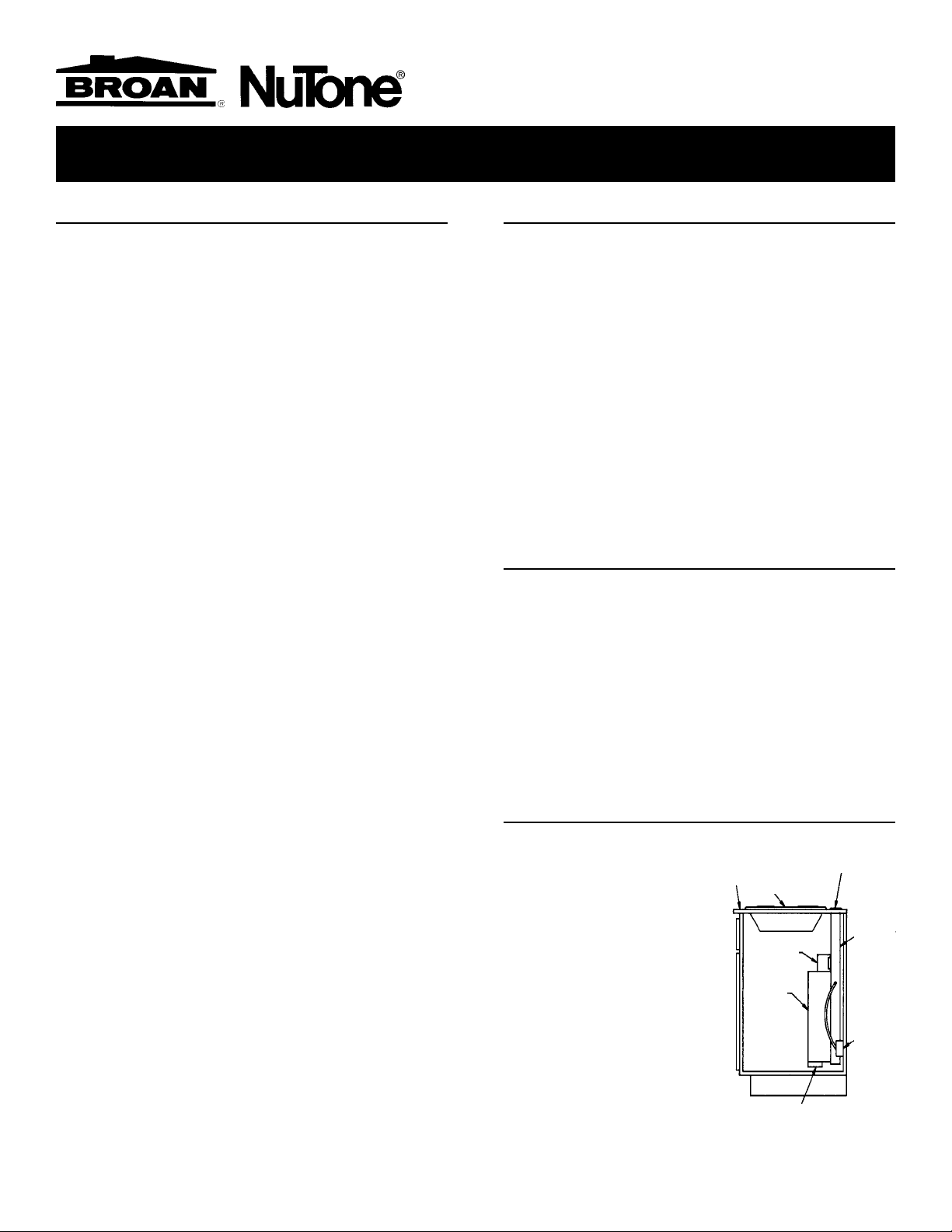
TYPICAL INSTALLATION
COUNTER
TOP
COOK TOP
BLOWER
CHIMNEY TOP
GEAR
MOTOR
COVER
BOX
3-1/4" X 10"
DUCT CONNECTOR
INSTALLER: Save this manual for Electrical Inspector and Homeowner to use.
HOMEOWNER: Use and Care Information on Page 5.
AIR
VENT
120 VAC
GROUNDED
OUTLET
Page 2
PLANNING - (continued)
Note: The high level of air flow of this appliance may affect the gas
flame on some types of gas cooktops. This is NORMAL and will
cause no harm, but can be corrected by lowering the speed of the
blower.
SPECIFICATIONS
VOLTS AMPS CFM DUCT
120 4.0 500 3-1/4 X 10
TAKE MEASUREMENTS
1. Refer to the cooktop installation instructions for dimensions of
cooktop, countertop cut-out, and cabinet requirements. The
Model 2730 will fit in most 30" wide cabinets and the Model
2736 will fit in most 36" wide cabinets. However, it is recommended that oversized cabinets be used for easier installation.
2. Cooktop depth can vary greatly from one to another. This may
cause the fit of these two appliances to be rather tight.
PLAN THE DUCTWORK
RIGHT
DISCHARGE
LEFT
DISCHARGE
DOWN
DISCHARGE
(as shipped)
1. This downdraft blower system is designed for use with 3-1/4"
x 10" ductwork (can be transitioned to 6" round). Three
different discharge directions are available with side-to-side
adjustment for accurate alignment of ductwork.
2. For best performance: Choose the ducting option which
allows the shortest length of ductwork and a minimum
number of elbows and transitions. Check location of floor
joists, wall studs, electrical wiring or plumbing for possible
interference. NOTE: The unit is shipped with the 3-1/4" x 10"
discharge facing DOWN. See “CHANGING BLOWER DIRECTION” on page 3, if necessary.
6" ROUND
ELBOW
3-1/4" X 10"
TO 6" RD.
TRANSITION
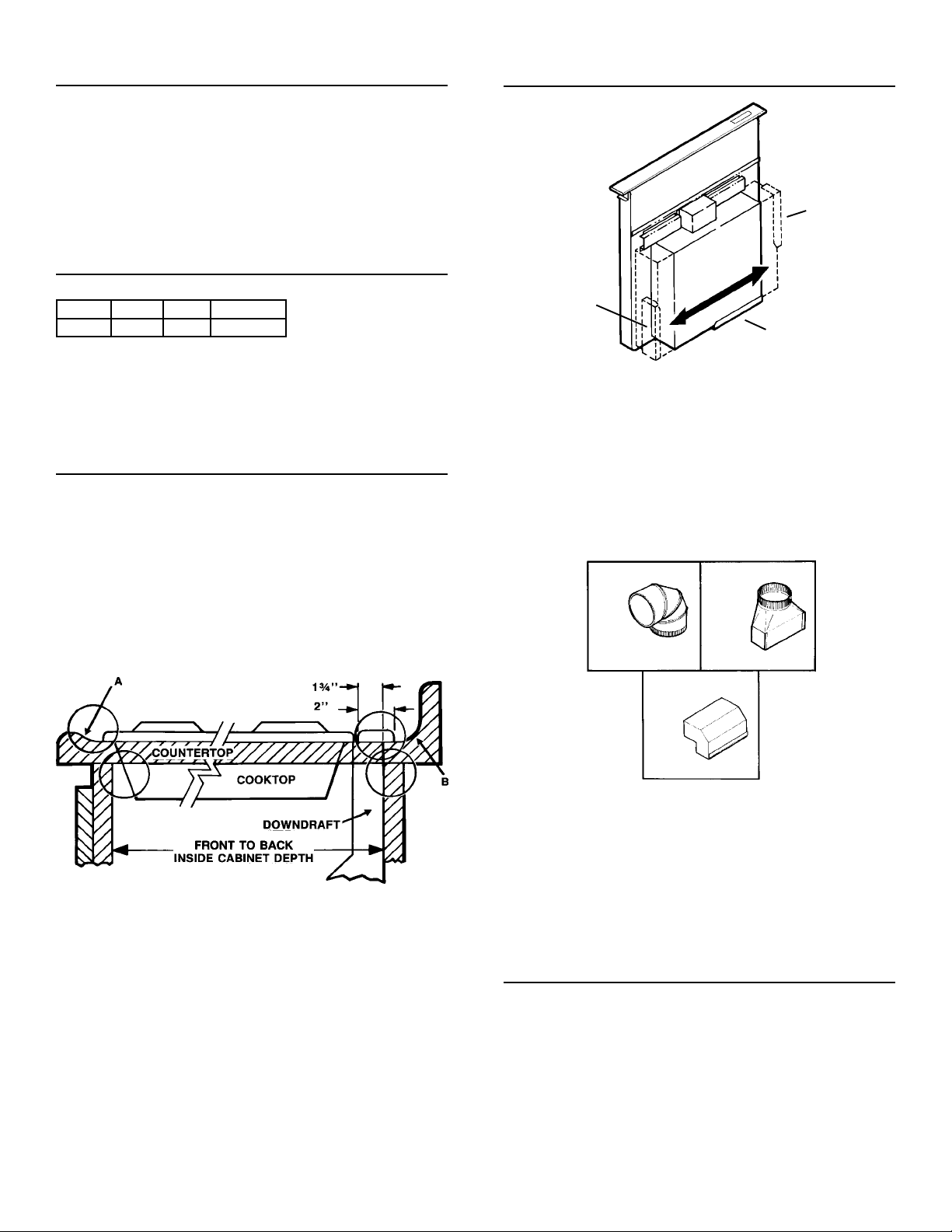
Pay special attention to the areas of potential interference
highlighted above. A countertop with (A) a raised lip and/or (B) a
backsplash may not allow enough flat countertop for a proper
installation. Note that 2" of flat countertop is required behind
cooktop and that 1-3/4" is necessary between the back edge of
the cooktop and the inside of cabinet back.
O
ELBOW
EQUALS 2
FT. OF
STRAIGHT DUCT
EQUALS 6 FT. OF
STRAIGHT DUCT
3-1/4" X 10"
90
EQUALS 8
FT. OF
STRAIGHT DUCT
3. The system will operate most efficiently when the ductwork
does not exceed 40 feet of equivalent duct. The chart, above,
shows equivalent feet of elbows and transitions. The number
of feet of straight duct plus the equivalent feet of transitions
and/or elbows to be used should equal 40 feet or less.
NOTE: The equivalent feet of various roof and wall caps has
been taken into consideration. Do not include them in this
calculation.
PLAN THE WIRING
1. The downdraft blower system draws 4 AMPS and requires a
120 VAC, 60 Hz circuit.
2. The unit has a 2 ft. long power cord with a 3-pronged plug.
Plan to provide a grounded outlet in a location which will allow
the unit’s power cord to reach. (Note: If the Model 2730 is
being installed in a 30" wide cabinet or the Model 2736 is being
installed in a 36" wide cabinet, the outlet cannot be located on
the back wall of cabinet.) Outlet may also be wall-mounted,
2
with access hole in cabinet.
Page 3
PREPARATION
CUT COUNTERTOP OPENING
CHANGING BLOWER DISCHARGE (Optional)
The blower is shipped with its discharge facing DOWN. Follow
these steps ONLY if:
the position of the blower discharge needs to be moved
•
so ductwork does not interfere with floor joists, plumb
ing or wiring below.
it is necessary to rotate the blower discharge to the
•
RIGHT or LEFT.
Place the unit on its back on a table or work surface.
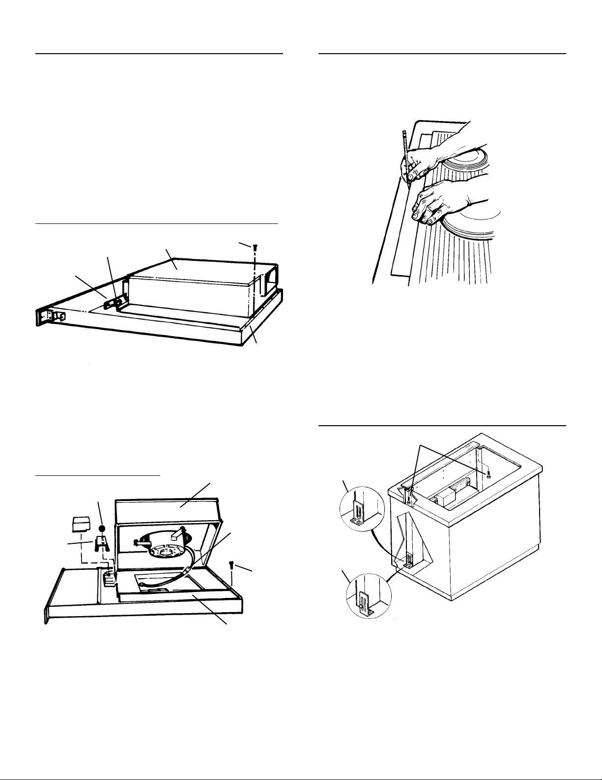
DOWN DISCHARGE - MOVING BLOWER LEFT OR RIGHT
NUTS
CLAMP
CHANNEL
Loosen
1.
2. Slide blower to desired position.
3. Use supplied cover plate to close open space (if any).
4. Tighten wing nuts to secure top of blower and use sheet metal
the 4 nuts and 2 clamp channels.
screws through bottom flange to secure bottom of blower.
BLOWER
SHEET
METAL
SCREW
BOTTOM
FLANGE
1. Lay out and cut the cooktop cut-out far enough FORWARD
so downdraft will fit behind it.
2. Set cooktop in place and slide it as far forward as possible.
Center and square it with edges of countertop.
3. Place the plastic template against the back flange of the
cooktop and center it. Trace around template to mark the
downdraft opening.
4. Remove cooktop from countertop.
5. Cut downdraft opening. Be careful not to chip edges of
countertop.
MOUNT THE UNIT
MOUNTING SCREWS
LEFT OR RIGHT DISCHARGE
BLOWER
NUT
MOTOR
CLAMP
CHANNEL
Remove
1.
2. Carefully lift blower and disconnect motor plug if necessary.
Reposition blower and RECONNECT MOTOR PLUG.
3. Use supplied cover plate to close open space (if any).
4. Replace clamp channels and use nuts to secure the blower
in its new position.
5. Use sheet metal screws through bottom flange to secure
bottom of blower.
the 4 nuts and 2 clamp channels.
PLUG
SHEET
METAL
SCREW
COVER PLATE
LEVELING BRACKET FLANGE FACING OUT
LEVELING BRACKET FLANGE FACING IN
1. Set downdraft into opening. Extend leveling brackets to floor
of cabinet so downdraft sits straight. (Note: Leveling brackets
can be removed and re-attached in other positions. Bottom
flange may have to face inward in tight cabinet installations.)
2. Secure the downdraft to the countertop as follows: Hold the
downdraft against the back of countertop cut-out and tightening the 2 mounting screws (one on each end of unit) on
underside of countertop. Use a wood shim between screw
and underside of granite countertops.
3. Screw leveling brackets to bottom of cabinet. Tighten screws
3
holding leveling bracket to unit on each side.
Page 4
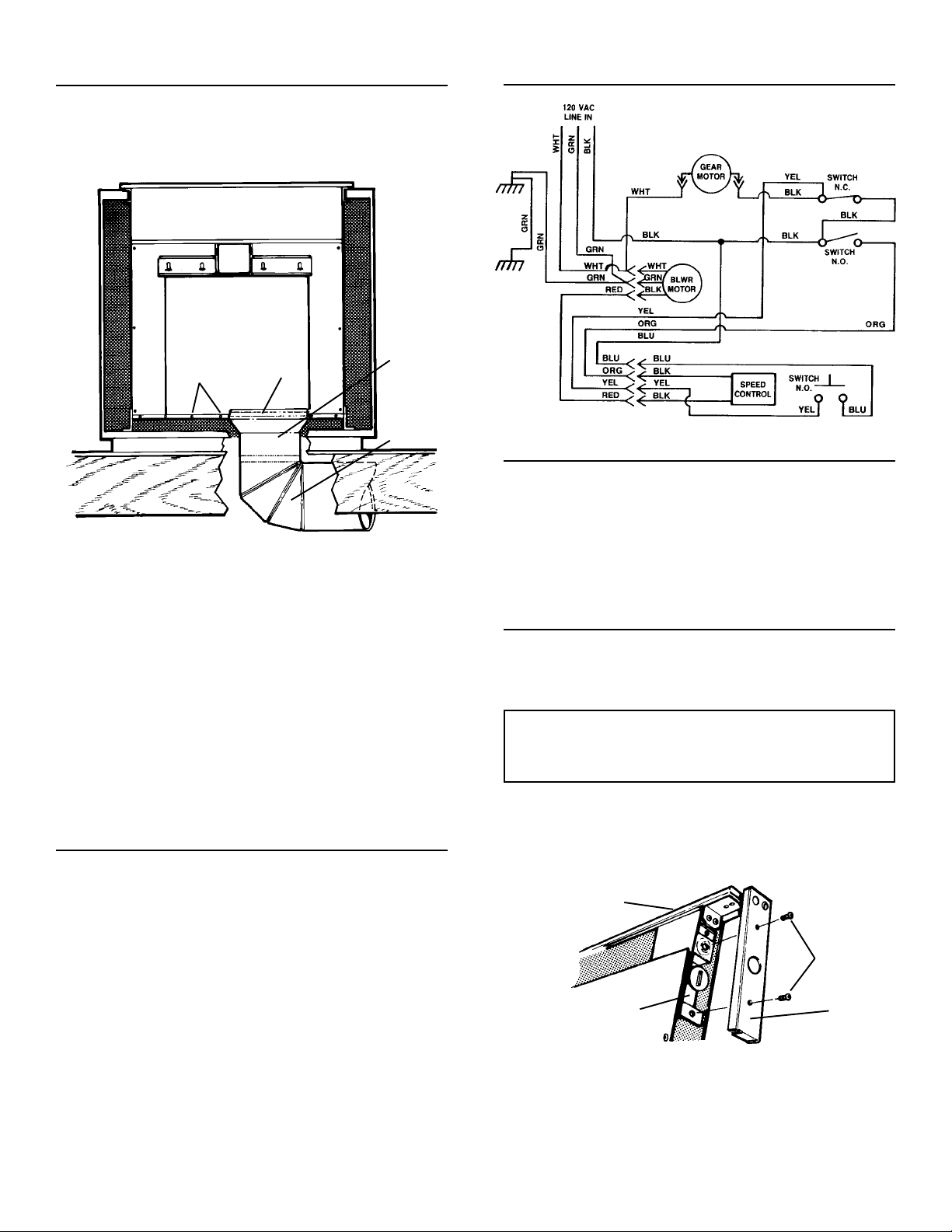
INSTALL DUCTWORK
WIRING DIAGRAM
CAUTION -
WORK:
electrical wiring or plumbing.
1. Cut hole in cabinet as well as holes in wall or floor as
necessary.
2. Mount the roof or wall cap and work back towards the cabinet,
attaching all ductwork, elbows and transitions as previously
planned. Tape all ductwork connections to make them secure
and air tight.
3. Connect ductwork (and transition, if required) to downdraft. If
necessary, LOOSEN nuts and screws that hold the blower in
place, and slide blower left or right to meet ductwork. Retighten screws and nuts.
Note: A 3-1/4" x 10" collar is provided for installers who prefer to
rivet the ductwork to the unit. This will allow blower to be removed
and replaced easily in service situations without disturbing
ductwork.
BEFORE CUTTING HOLE IN CABINET FOR DUCT-
Check for interference with floor joists, wall studs,
ç BLOWER è
SCREWS
COLLAR
3-1/4" X 10"
TO 6" RD.
TRANSITION
6" RD.
ELBOW &
DUCTWORK
INSTALL ELECTRICAL WIRING
INSTALL COOKTOP
1. Align the cooktop with the downdraft and fasten cooktop in
place.
Note: Accurate alignment of cooktop and downdraft is necessary
to ensure that there is no interference when air vent is raised and
lowered. There should be a gap of 1/32"-1/16" between the back
of the cooktop and the front of the downdraft cover.
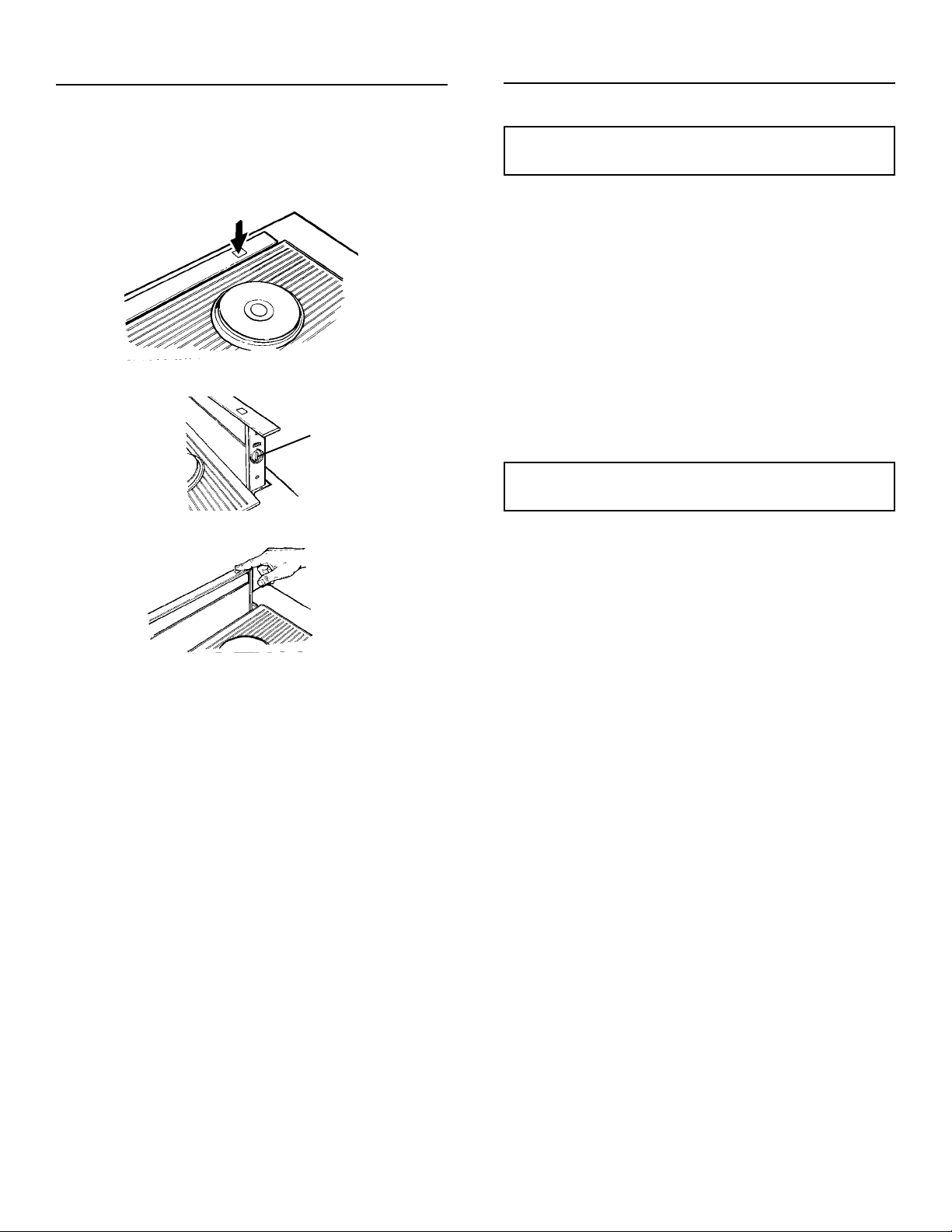
ADJUSTMENT
The downdraft is factory-adjusted for proper operation. However, shipping and handling may affect the position of the
activating switch.
To adjust position of activating switch:
WARNING: To avoid possible electrical
shock, personal injury or death Disconnect electrical power.
1. If downdraft is plugged into electrical outlet, unplug it.
2. Lift air vent straight up and cock it slightly so it remains in the
UP position.
1. Mount a standard wiring box, with 3-pronged receptacle,
inside the cabinet. Make sure the downdraft’s power cord can
easily reach it.
2. Run appropriate power cable into cabinet and connect it to
receptacle.
3. Plug the downdraft’s power cord into the outlet.
SWITCH
MEMBRANE
SCREWS
SWITCH
BRACKET
3. Remove switch cover from right end of air vent.
4. Loosen the 2 screws holding the switch bracket in place.
Position switch bracket so that activating switch just comes in
contact with underside of switch membrane. Tighten screws.
5. Replace switch cover, gently lower air vent into chimney, and
4
plug in power cord. Re-connect electrical power and check
operation.
SWITCH
COVER
Page 5
USE AND CARE
Always turn the downdraft blower on before you begin cooking to
establish an air flow in the kitchen. Let the blower run for a few
minutes to clean the air after you turn the cooktop off. This will
keep the whole kitchen cleaner and brighter.
USE AND CARE - (Continued)
CLEANING
WARNING: Always disconnect electric
power supply before cleaning unit.
CONTROLS
Turn the downdraft blower ON by pressing down on the activating
switch. The air vent will rise.
KNOB
The blower can be turned ON or OFF and its speed can be
adjusted with the recessed knob on the right side of the air vent.
Turn the downdraft blower OFF by pressing the activating switch
again. The air vent will go down and the blower will shut OFF.
Note: For most convenient operation, set the blower to your
favorite speed. The blower will come on to this speed whenever
the activating switch is pressed and the air vent rises.
Use a mild detergent suitable for painted surfaces. DO NOT USE
ABRASIVE CLOTH, STEEL WOOL PADS, OR SCOURING
POWDERS. Vacuum blower to clean. Do not immerse blower in
water.
Wash the 2 aluminum grease filters in a mild detergent solution
or a dishwasher. Remove them from the air vent by grasping the
tab at the top of each filter.
Note: The filters are different sizes. Be sure to replace them as
removed, (wider one on the left), with tabs UP.
SERVICING
WARNING: Always disconnect electric
power supply before servicing unit.
It may be necessary to remove the downdraft blower system
from the cabinet in order to service components such as the
blower motor or air vent mechanism.
Disconnect power to the cooktop and remove it first. Reverse the
steps under “MOUNT THE UNIT” to remove the downdraft from
the cabinet.
Service parts are available from your local Broan distributor or
from the Broan Service Department, P.O. Box 140, Hartford, WI
53027 Phone: 1-800-637-1453.
5
Page 6
SERVICE PARTS
Models 2730 & 2736
Downdraft Blower Systems
.ONYEK.ONYEK
.ONYEK.ONYEKREBMUNTRAPREBMUNTRAP
.ONYEK
183000439"8/7,gnihsuB1
216000499"8/5,ocyeHtilpS,gnihsuB1
342000499"2/1,ocyeH,gnihsuB1
421007439relloR1
583211079nwoD/pU,ylbmessAhctiwS1
641701079lortnoCdeepS,ssenraHeriW1
71940629923-8/3,tuN1
856106399bonK1
948400199rotalosnIrotoM3
0127990079ylbmessAtekcarBhctiwSrewoL1
1139211079eriWdnuorGneerG1
2139901079ssenraHeriW1
6124670089etalPpu-kcaB1
7108770089knarC1
8186180089revoChctiwS1
9152311079)0372ledoM(edilShtiwylbmessAyenmihC1
0226308099)37.oNyeK-roticapaChtiw(rotoM1
1274202099leehWrewolB1
2276180089noisnetxExoBllorcS1
3223001799recapS3
4295211079thgiR,ylbmessAtekcarBpoT1
5206211079tfeL,ylbmessAtekcarBpoT1
6222311079)0372ledoM(sselniatS,poT1
8219901079ylbmessAxoBllorcS1
9234411079revoCrotoMraeG1
0349901079)0372ledoM(ylbmessAxoBriA1
1305180089revoCxoBllorcS1
2375180089partSroticapaC1
3368790079)sretilf2sniatnoc()0372ledoM(tiKretliF1
5450909099paCdnE1
6459208099rotomraeG1
7405801199pirtSedilS4
9454207199DHSWXHTLS573.x81-8#,wercS91
0517405199HRDBSWXH005.x23-01#,wercS2
1519405199HRTHPRS573.x81-8#,wercS6
2588405199mirTHP5.oN005.x81-8#,wercS2
3585180089)0372ledoM(gninepOxoBriA,revoC1
458840629942-01#,tuN4
5544180089)0372ledoM(revoCxoBriA1
6500511079ylbmessAtekcarBrotomraeG1
7595180089troppuSgeL2
856350519961/5x02-4/1,wercS5
95729052994/1,rehsaW2
0652206199SMDHHP2/1x23-8#,wercS4
1665306199KCOLHWHS8/3x42-01#,wercS1
2616306199DLDHLFHP8/3x42-01#,wercS1
4673406299SPEKXEH42-01,tuN7
5677406299KCOLZIHW02-4/1,tuN3
663360839942-01,tloB-U1
7684000499feileRniartS1
8674406239egnalFxeH,tuN1
0751480089pmalClennahCeriW2
1739407239eiTeriW3
3700017299roticapaC1
4728306199DHXEH052.1x02-4/1,wercS2
5751405199TPBDHRTHP052.x81-8#2
4830500199)"03(maoF-laeS1
**11311079.soNyeKsedulcnI(etelpmoC,ylbmessArewolB
**02311079)0372ledoM(etelpmoC,ylbmessAyenmihC
**12311079)6372ledoM(etelpmoC,ylbmessAyenmihC
*Standard Hardware - May be purchased locally.
**Service Assembly - Contains numerous parts.
REBMUNTRAPREBMUNTRAPNOITPIRCSEDNOITPIRCSED
REBMUNTRAP
62311079)6372ledoM(edilShtiwylbmessAyenmihC1
32311079)6372ledoM(sselniatS,poT1
29901079)6372ledoM(ylbmessAxoBriA1
78790079)sretilf2sniatnoc()6372ledoM(tiKretliF1
58180089)6372ledoM(gninepOxoBriA,revoC1
96180089)6372ledoM(revoCxoBriA1
40500199)"63(maoF-laeS1
NOITPIRCSEDNOITPIRCSED.YTQ.YTQ
NOITPIRCSED
)37&,56,46,85,94,23,13,82,22,12,02,9,2
)17&,25,15,54,91,8,5.soNyeKsedulcnI(
)17&,25,15,54,91,8,5.soNyeKsedulcnI(
6
.YTQ.YTQ
.YTQ
OPTIONAL DOOR KITS
MODEL NO. DESCRIPTION
273001C 30" White
273002C 30" Biscuit
273023C 36" Black
273601C 36" White
273602C 36" Biscuit
273623C 36" Black
Page 7
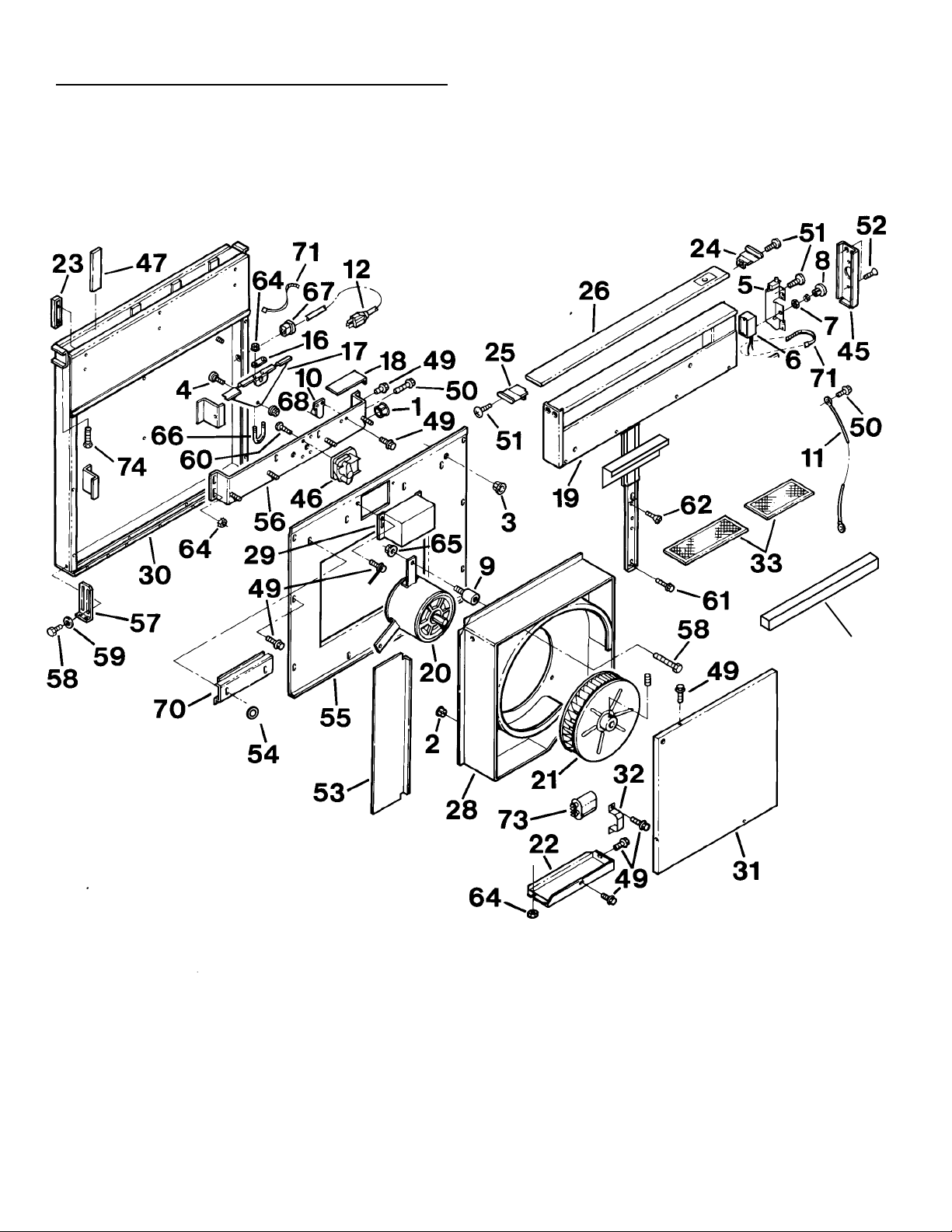
SERVICE PARTS
Models 2730 & 2736
Downdraft Blower Systems
75
84
7
Page 8

WARRANTY
Broan-NuTone warrants to the original consumer purchaser of its products that such
products will be free from defects in materials or workmanship for a period of one year from
the date of original purchase. THERE ARE NO OTHER WARRANTIES, EXPRESS OR
IMPLIED, INCLUDING, BUT NOT LIMITED TO, IMPLIED WARRANTIES OF MERCHANTABILITY OR FITNESS FOR A PARTICULAR PURPOSE.
During this one-year period, Broan-NuTone will, at its option, repair or replace, without
charge, any product or part which is found to be defective under normal use and service.
THIS WARRANTY DOES NOT EXTEND TO FLUORESCENT LAMP STARTERS AND
TUBES. This warranty does not cover (a) normal maintenance and service or (b) any
products or parts which have been subject to misuse, negligence, accident, improper
maintenance or repair (other than by Broan-Nutone), faulty installation or installation contrary
to recommended installation instructions.
BROAN-NUTONE ONE YEAR LIMITED WARRANTY
The duration of any implied warranty is limited to the one-year period as specified for the
express warranty. Some states do not allow limitation on how long an implied warranty lasts,
so the above limitation may not apply to you.
BROAN-NUTONE’S OBLIGATION TO REPAIR OR REPLACE, AT BROAN-NUTONE'S
OPTION, SHALL BE THE PURCHASER’S SOLE AND EXCLUSIVE REMEDY UNDER
THIS WARRANTY. BROAN-NUTONE SHALL NOT BE LIABLE FOR INCIDENTAL,
CONSEQUENTIAL OR SPECIAL DAMAGES ARISING OUT OF OR IN CONNECTION
WITH PRODUCT USE OR PERFORMANCE. Some states do not allow the exclusion or
limitation of incidental or consequential damages, so the above limitation or exclusion may
not apply to you.
This warranty gives you specific legal rights, and you may also have other rights, which vary
from state to state. This warranty supersedes all prior warranties.
To qualify for warranty service, you must (a) notify Broan-Nutone at the address stated below
or telephone: 1-800-637-1453, (b) give the model number and part identification and (c)
describe the nature of any defect in the product or part. At the time of requesting warranty
service, you must present evidence of the original purchase date.
Broan-NuTone LLC, 926 West State Street, Hartford, WI 53027 (1-800-637-1453)
NuTone, Inc., 4820 Red Bank Road, Cincinnati, OH 45227 (1-800-543-8687)
99041818L
 Loading...