

Page 1
Installation and User Manual
Address of your installer
06095 rev. A
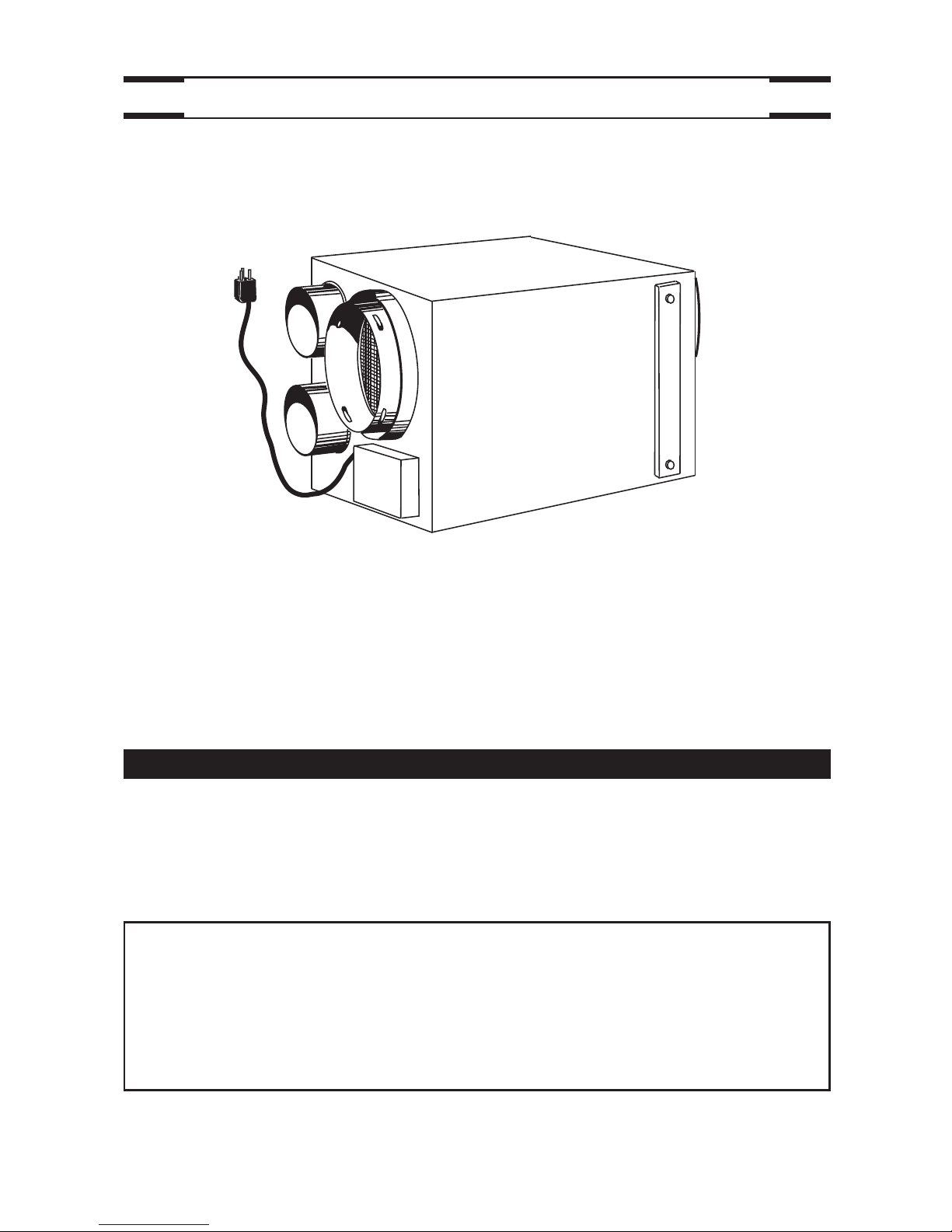
AE60 / EA 1500 / HV 1.5
VB0063
RESIDENTIAL USE ONLY
INSTALLER: LEAVE THIS MANUAL WITH THE HOMEOWNER.
HOMEOWNER: USE AND CARE INFORMATION ON PAGES 20 TO 24.
READ AND SAVE THESE INSTRUCTIONS
Page 2

2
!
TO REDUCE THE RISK OF FIRE, ELECTRIC SHOCK, OR INJURY TO PERSON(S)
OBSERVE THE FOLLOWING:
1. This unit is intented for residential installation only.
2. Use this unit only in the manner intended by the manufacturer. If you have questions,
contact the manufacturer at the address or telephone number listed in the warranty.
3. Before replacing filters, servicing or cleaning unit, disconnect power cord from
electrical outlet.
4. Installation must be done in accordance with all applicable codes and standards,
including fire-rated construction codes and standards.
5. This unit is not designed to provide combustion and/or dilution air for fuel-burning
appliances.
6. When cutting or drilling into wall or ceiling, do not damage electrical wiring and other
hidden utilities.
7. Do not use this unit with any solid-state speed control device other than optional wall
controls C34, CMR or ACCGSC3.
8. This unit must be grounded. The power supply cord has a 3-prong grounding plug for
your personal safety. It must be plugged into a mating 3-prong grounding receptacle,
grounded in accordance with the national electrical code and local codes and
ordinances. Do not remove the ground prong. Do not use an extension cord.
9. Do not install in a cooking area or connect directly to any appliances.
10. Do not use to exhaust hazardous or explosive materials and vapors.
11. Do not run any air ducts directly above or closer than 2 ft (0.61 m) to any furnace or
its supply plenum, boiler, or other heat producing appliance. Do not connect the unit
ducts to the furnace ducts, neither return plenum or supply.
12. When performing installation, servicing or cleaning the unit, it is recommended to
wear safety glasses and gloves.
13. When the federal, provincial or state legislation comprises more restrictive installation
and/or certification requirements, the aforementioned requirements prevail on those
of this document and the installer agrees to conform to these at his own expenses.
CAUTION
1. To avoid premature clogged filters, turn OFF the unit during construction or renovation.
2. Please read specification label on product for further information and requirements.
3. Be sure to duct air outside – Do not intake / exhaust air into spaces within walls or
ceiling or into attics, crawl spaces, or garage.
4. Intended for residential installation only in accordance with the requirements of NFPA 90B.
5. The ductwork is intended to be installed in compliance with all local and national
codes that are applicable.
6. Do not use the AE60, EA 1500 or HV 1.5 unit when varnishing. Furthermore, if the
unit is installed in the attic, it is highly recommended to block the stale air intake and
fresh air register. The varnish vapors may damage the unit.
7. At least once in a year, the unit mechanical and electronic parts should be inspected
by qualified service personnel.
8. If the AE60, EA1500 or the HV 1.5 unit is installed in the attic, the unit should not be
turned off during the winter time in order to avoid condensation inside the unit and
inside the ducts.
9. During snow/rain storm, operate the unit in recirculation mode to prevent water build
up in the ventilator.
WARNING
Page 3
1. YOUR UNIT AND ITS PURPOSE . . . . . . . . . . . . . . . . . . . . . . . . .4
2. TYPICAL INSTALLATIONS . . . . . . . . . . . . . . . . . . . . . . . . . . . . .5
2.1 Basement Installation . . . . . . . . . . . . . . . . . . . . . . . . . . . . . . . . . . . . . . . .5
2.2 Attic Installation . . . . . . . . . . . . . . . . . . . . . . . . . . . . . . . . . . . . . . . . . . . .5
2.3 Mounting Considerations . . . . . . . . . . . . . . . . . . . . . . . . . . . . . . . . . . . . .6
3. INSTALL THE UNIT . . . . . . . . . . . . . . . . . . . . . . . . . . . . . . . . . .7
3.1 Locating and Mounting the Unit . . . . . . . . . . . . . . . . . . . . . . . . . . . . . . . .7
3.2 Tools and Materials . . . . . . . . . . . . . . . . . . . . . . . . . . . . . . . . . . . . . . . . .7
3.3 How to Hang the Unit . . . . . . . . . . . . . . . . . . . . . . . . . . . . . . . . . . . . . . . .7
3.4 Planning of the Ductwork . . . . . . . . . . . . . . . . . . . . . . . . . . . . . . . . . . . . .8
3.5 Installing 6’’ Ducts and Registers . . . . . . . . . . . . . . . . . . . . . . . . . . . .8-10
3.6 Insulated Flexible Ducts Installation . . . . . . . . . . . . . . . . . . . . . . . . . . . .11
3.7 Exterior Opening(s) Installation . . . . . . . . . . . . . . . . . . . . . . . . . . . . .11-17
4. WALL CONTROL . . . . . . . . . . . . . . . . . . . . . . . . . . . . . . . . . .18
4.1 Installation of the Wall Control . . . . . . . . . . . . . . . . . . . . . . . . . . . . .18-20
4.2 Operating the Wall Control . . . . . . . . . . . . . . . . . . . . . . . . . . . . . . . .20-21
5. MAINTENANCE . . . . . . . . . . . . . . . . . . . . . . . . . . . . . . . . . . .22
5.1 Biannual Maintenance . . . . . . . . . . . . . . . . . . . . . . . . . . . . . . . . . . . . . .22
5.2 Annual Maintenance . . . . . . . . . . . . . . . . . . . . . . . . . . . . . . . . . . . . . . . .23
5.3 Master Reset . . . . . . . . . . . . . . . . . . . . . . . . . . . . . . . . . . . . . . . . . . . . .24
6. TROUBLESHOOTING . . . . . . . . . . . . . . . . . . . . . . . . . . . . . . .24
3
TABLE OF CONTENTS
The purpose of this guide is to help you to install properly your unit, and to show you how to
operate and do the maintenance. Please read completely before starting the installation.
Please note the illustrations are typical ones.
We welcome any suggestions you may have concerning this manual and/or the unit, and
we would appreciate hearing your comments on ways to better serve you. Please forward
all correspondence to us at the address indicated on the product registration card included
with this manual.
This manual uses the following symbols to emphasize particular information:
NOTE: Indicates supplementary information needed to fully complete an instruction.
Finally, we want to congratulate you on your purchase of this excellent unit which will
allow you and your family to enjoy fresh air throughout your home for years to come!
NOTE: The unit does not require balancing because of its design.
ABOUT THIS MANUAL/PRODUCT
WARNING
Identifies an instruction which, if not followed, might cause serious
personal injuries including possibility of death.
!
CAUTION
Denotes an instruction which, if not followed, may severely damage the
unit and/or its components.
Page 4
VF0035
OPERATIONAL PRINCIPLES
4
1. YOUR UNIT AND ITS PURPOSE
VF0034
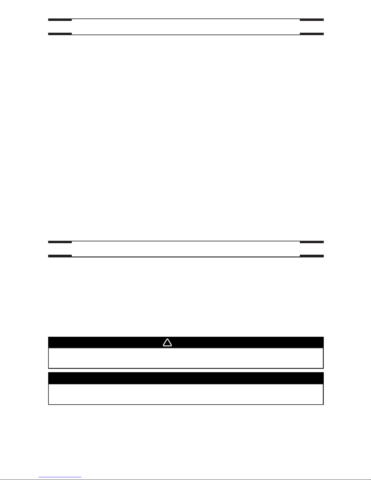
CIRCULATION WITH AIR EXCHANGE:
While continually circulating the air within the house, the unit also evacuates part of this
stale air and replaces it with fresh dry air from the outside. The following extra benefits
are thus obtained: expelling the excess of humidity during the winter months, ventilate the
house on hot summer nights, elimination of stale air.
The air exchanger is designed to eliminate problems of excessive humidity, to steady the
temperature and the humidity and to filter and purify the air inside your house. The air
exchanger carries out the following operations:
AIR RECIRCULATION:
The system recirculates the air inside the house, without exchanging with the outside.
This operation steadies the temperature and the humidity throughout.
FILTRATION:
When the air flows through the system, a mechanical filter traps dust particles.
F
RESH AIR TO
BUILDING
FILTERED AIR
TO BUILDING
STALE AIR TO
OUTSIDE
FRESH AIR
FROM OUTSIDE
STALE AIR
FROM BUILDING
STALE AIR
FROM BUILDING
Page 5
5
2. TYPICAL INSTALLATIONS
VH0053
Only one outside connection is needed when
using the Tandem® transition* and the dual
outside port*, simplifying the installation. These
two components are included in the installation
kit no. 15273 (purchase separately).
NOTES: 1. See Point 2.3
MOUNTING
CONSIDERATIONS
on next page
for required joists opening.
2. The installation kit no. 15273 is not
available in the U.S.A.
*Patented.
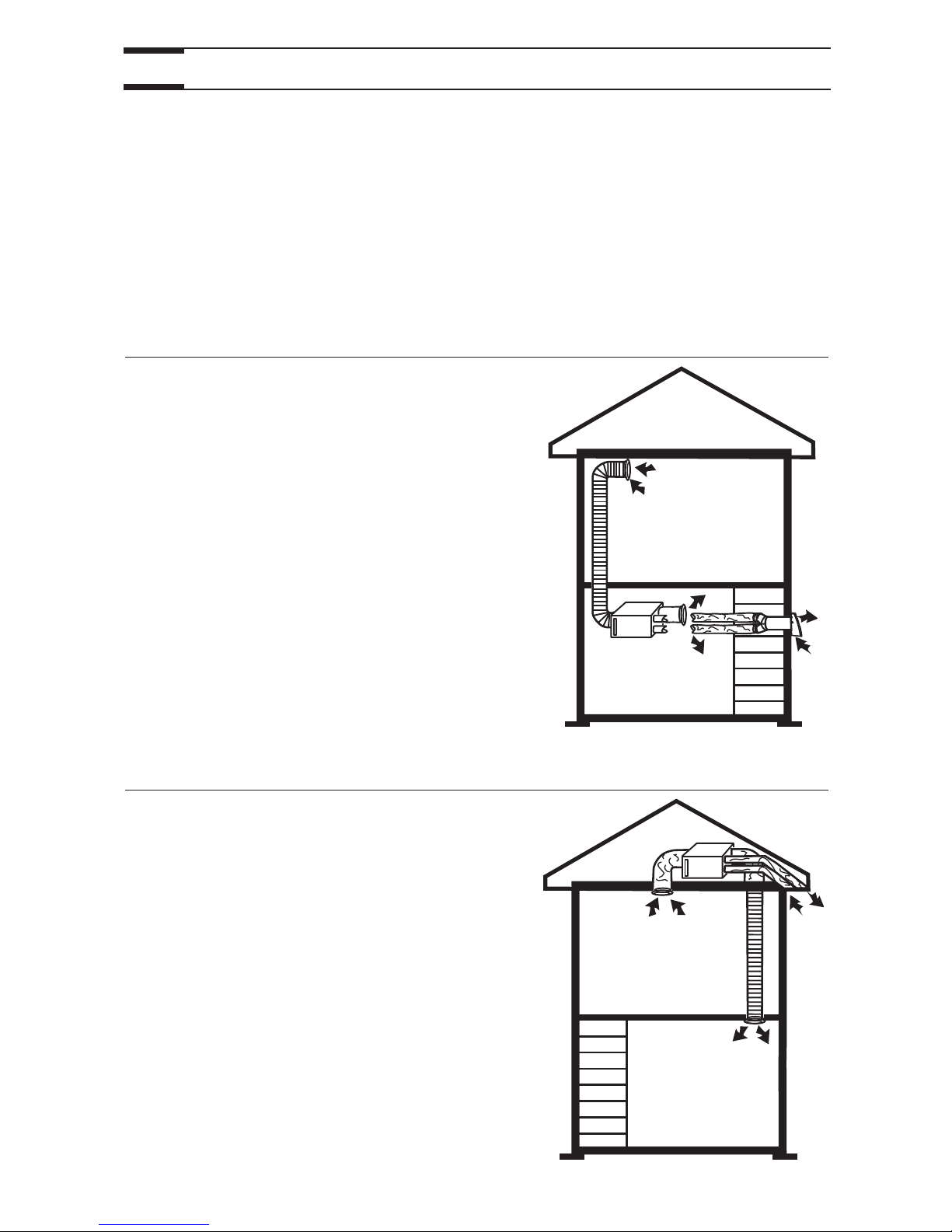
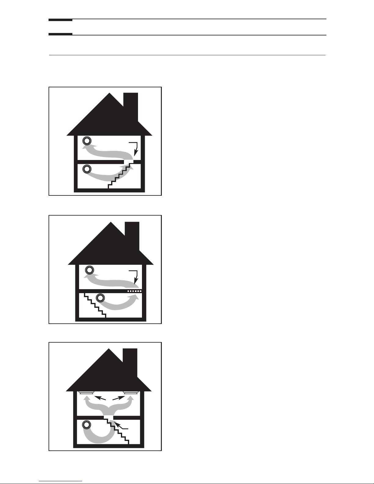
If the unit is installed in the attic, this unit must
always be in operation during the winter season.
Use the installation kit no. EA20130 (purchase
separately).
NOTE: The installation kit no. EA20130 is not
available in the U.S.A.
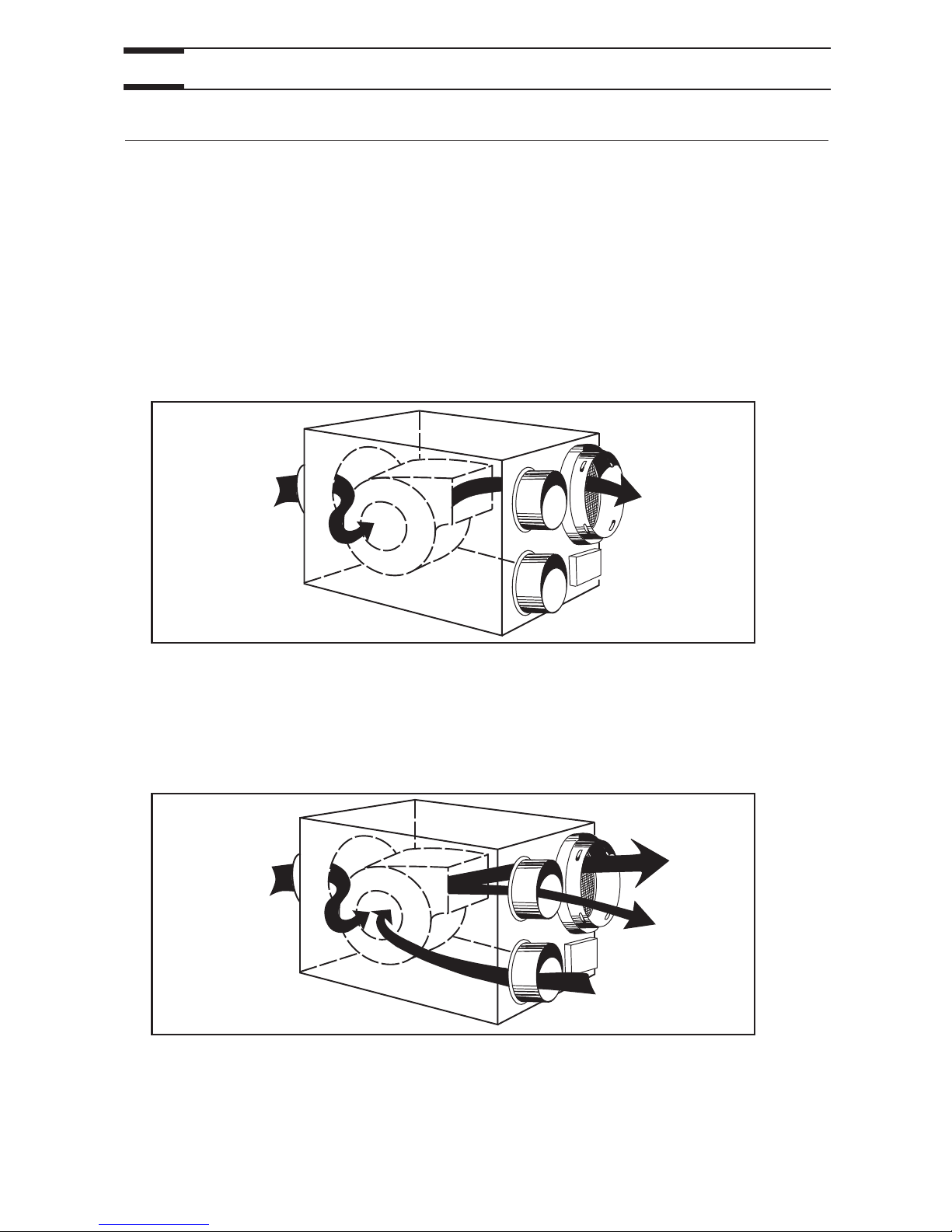
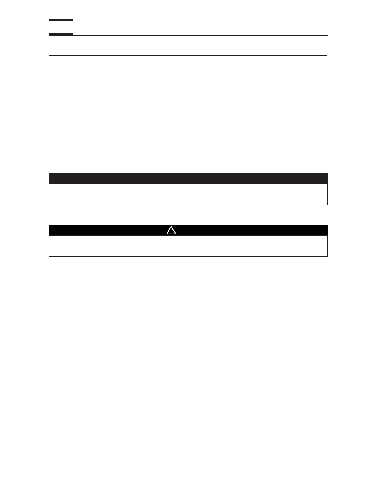
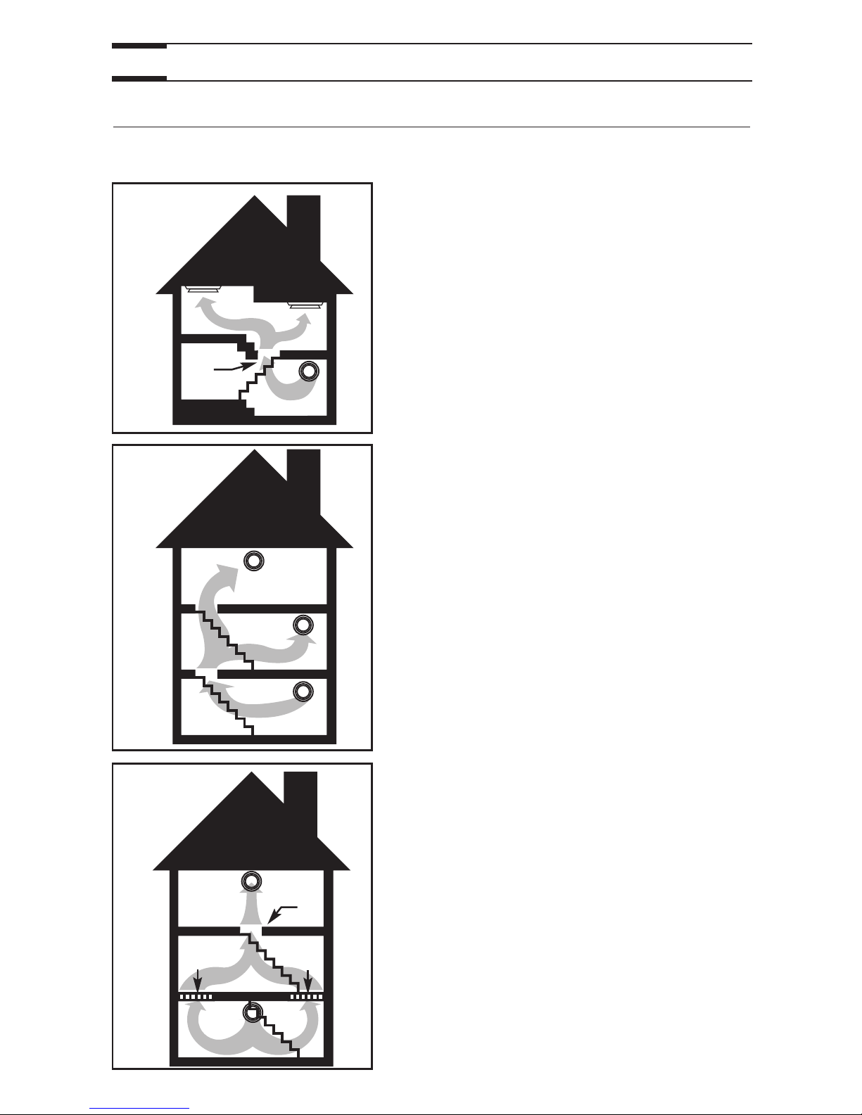
2.1 BASEMENT INSTALLATION
VH0004
2.2 ATTIC INSTALLATION
Use the following illustrations as guidelines to help you decide where your unit will be
installed. The unit should be hung to the joists, using chains and springs (included). If
needed, this unit can be installed upside down. For more details, see Point 3.
INSTALL
THE UNIT
.
In every case, bathroom fan and a range hood should be used to exhaust stale air. Also,
for homes with more than one level, we recommend one exhaust register at the highest
level.
NOTE: An electrical outlet (standard 3-prong grounding outlet) has to be available within
3 feet from the unit.
Page 6
6
2. TYPICAL INSTALLATIONS (CONT’D)
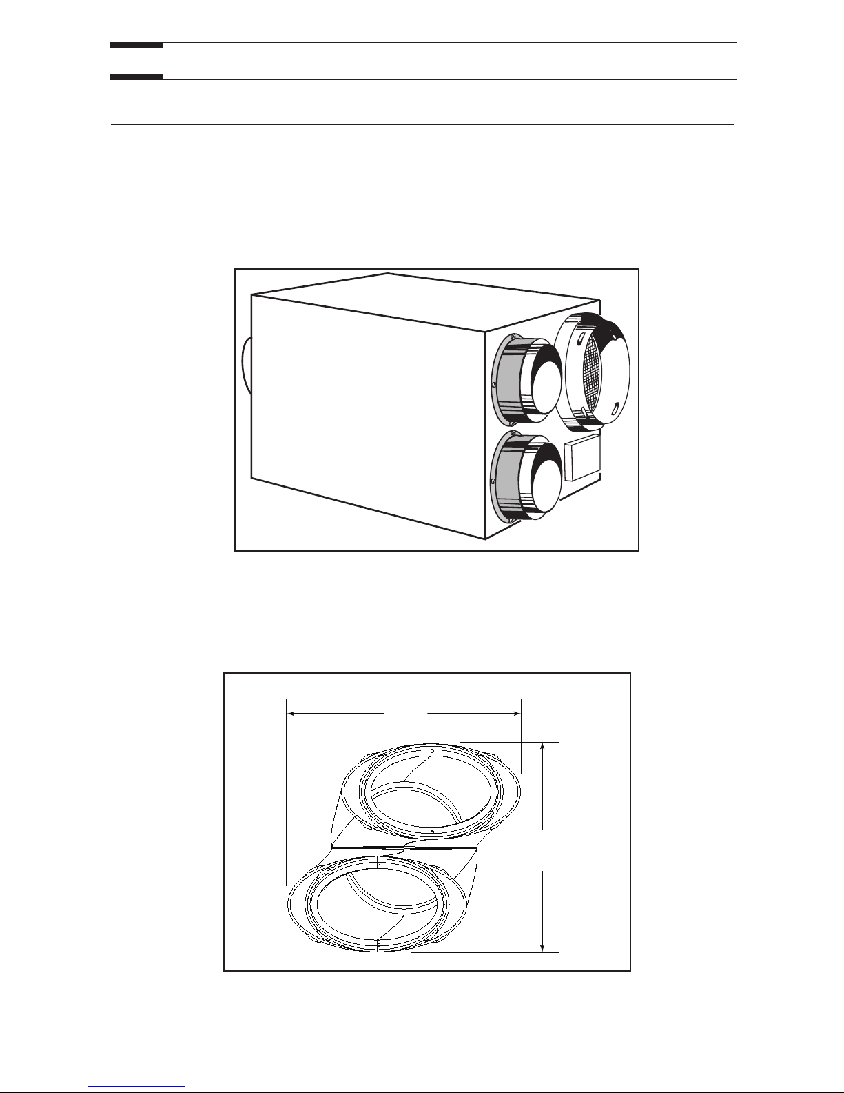
This unit can be used for a retrofit application. Connect the existing ducts to the corresponding
unit ports. If the previous stale air to outside duct and fresh air from outside duct are 5’’
diameter, install the 5’’ diameter adapters (included) over each of the corresponding unit
ports. Also, if using the installation kit no. 15273 or no. EA20130 (not available in the
U.S.A.), install these 5’’ diameter adapters. Use 4 screws (included) per adapter to attach
them to the unit. See figure below.
The joists opening needed to install the Tandem transition must be 9¾’’ (248 mm)
minimum. Also, the maximum heigh of the tandem transition is 8¾’’ (222 mm). See
Tandem transition end view below.
NOTE: The Tandem transition is included in the installation kit no. 15273 (not
available in U.S.A.).
2.3 MOUNTING CONSIDERATIONS
VJ0030
VD0118A
8¾”
222 mm
9¾”
248 mm
Page 7
7
3. INSTALL THE UNIT
Choose an appropriate location for the unit, far from the areas of the house where peace
and quiet are desired.
• So as to provide easy access for filter maintenance (sometimes, by
installing the unit upside down, it becomes easier to get at the filter).
• Close to an exterior wall, so as to limit the length of the insulated flexible
ducts to and from the unit.
• Away from hot chimneys and other fire hazards.
• Allow for a power source (standard 3-prong grounding outlet).
3.1 LOCATING AND MOUNTING THE UNIT
• Phillips screwdriver no. 2 or Robertson no. 2
• Scissors or utility knife (to cut duct tape and flexible ducts)
• Duct tape
• Jig saw
• A pair of metal shears (if the exterior covering of the house is aluminum
or vinyl)
• A chisel and hammer (if the exterior covering of the house is brick)
• Caulking gun and caulking
3.2 TOOLS AND MATERIALS
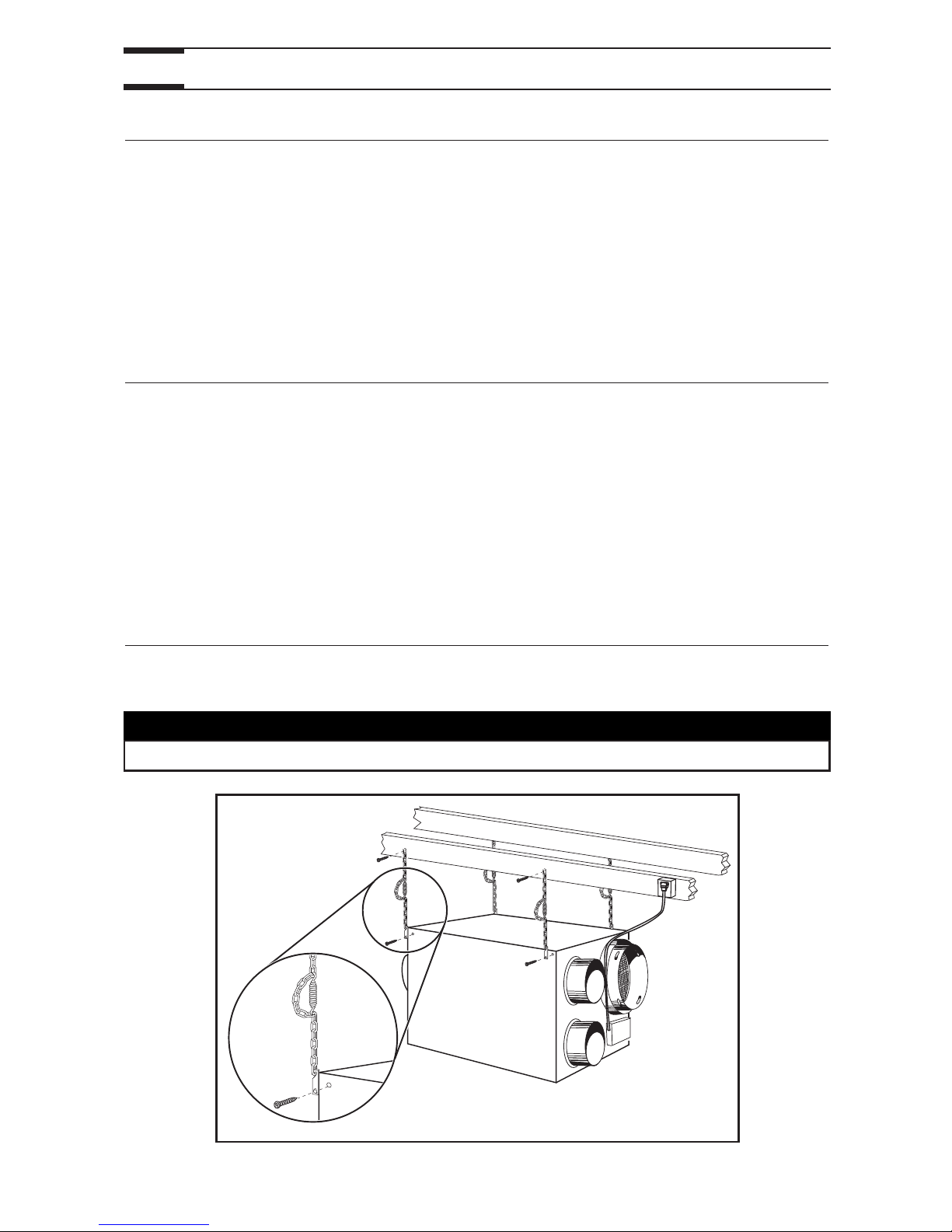
Use the 4 chains and springs in the hardware pack provided with the unit. According to
your needs, the unit can be installed upside down.
3.3 HOW TO HANG THE UNIT
VD0156
CAUTION
Make sure the unit is level.
Page 8
8
3. INSTALL THE UNIT (CONT’D)
• Keep it simple. Plan for a minimum number of bends and joints. Keep the
length of the insulated ducts to a minimum.
• Do not use wall cavities as ducts. Do not use branch lines smaller than
4’’ (102 mm) diameter.
• Do not ventilate crawl spaces or cold room. Do not attempt to recover the
exhaust air from a dryer or a range hood, this would cause the clogging of
the unit.
• Be sure to plan at least one exhaust register on the highest lived-in level of
the house, if it has 2 floors or more.
3.4 PLANNING OF THE DUCTWORK
• Install the stale air exhaust register(s) in the main area where the contaminants
are produced: kitchen, living room, etc. Position the register(s) as far from
the stairway as possible and in such a way that the air circulates in all the
lived-in spaces in the house.
• If a register is installed in the kitchen, it must be located at least 4 feet (1.2 m)
from the range.
• Install the register(s) 6 to 12 inches (152 to 305 mm) from the ceiling on an
interior wall OR install it in the ceiling.
• Attach one end of the 6’’ flexible duct to the stale air exhaust register, and
the other end to the unit stale air from building port, using tie wrap and duct
tape.
3.5 INSTALLING 6’’ DUCTS AND REGISTERS
WARNING
Never install a stale air exhaust register in a room where a combustion
device operates, such as a gas water heater, a gas furnace or a fireplace.
!
3.5.1 STALE AIR EXHAUST DUCTWORK
• Install the fresh air distribution register(s) in a large, open area in the lowest
level to ensure the greatest possible air circulation. Keep in mind that the fresh
air register(s) must be located as far as possible from the stale air register(s).
• Install the register(s) in the ceiling OR 6 to 12 inches (152 to 305 mm) from
the ceiling on an interior wall. The duct length should be at least 15’ (4.6 m).
(The cooler air will then cross the upper part of the room and mix with room
air before descending to occupant level.)
• Attach one end of the 6’’ flexible duct to the fresh air distribution register,
and the other end to the unit fresh air to building port, using tie wrap and
duct tape.
3.5.2 FRESH AIR DISTRIBUTION DUCTWORK
CAUTION
If ducts have to go through an unconditioned space, always use insulated
ducts (purchase separately).
Page 9
3. INSTALL THE UNIT (CONT’D)
3.5 INSTALLING 6’’ DUCTS AND REGISTERS (CONT’D)
3.5.3 SUGGESTED REGISTER LOCATIONS
VA0032
BUNGALOW
Basement stairwell (A): Open, lateral.
One stale air exhaust register (1) in the highest
lived-in level of the house and one fresh air
distribution register (2) in the lowest lived-in
level of the house.
1
2
A
VA0033
BUNGALOW
Basement stairwell (A): Closed.
One stale air exhaust register (1) in the highest
lived-in level of the house and one fresh air
distribution register (2) in the lowest lived-in
level of the house. For the closed stairwell, use
floor grilles (A).
1
2
A
VA0034
BUNGALOW
Basement stairwell (A): Open, central.
Two stale air exhaust registers (1) in the highest
lived-in level of the house and one fresh air
distribution register (2) in the lowest lived-in
level of the house.
2
A
1
9
Page 10
3. INSTALL THE UNIT (CONT’D)
3.5 INSTALLING 6’’ DUCTS AND REGISTERS (CONT’D)
3.5.3 SUGGESTED REGISTER LOCATIONS (CONT’D)
VA0035
MULTI-LEVEL
Stairwell (A): Open, central.
Two stale air exhaust registers (1) in the upper
lived-in levels of the house and one fresh air
distribution register (2) in the lowest lived-in
level of the house.
1
1
2
A
VA0036
COTTAGE
Basement stairwell (A): Open.
Two stale air exhaust registers (1) in the upper
lived-in levels of the house and one fresh air
distribution register (2) in the lowest lived-in
level of the house.
1
1
2
A
A
VA0037
COTTAGE
Basement stairwell (A): One part open, some
parts closed (B).
One stale air exhaust register (1) in the highest
lived-in level of the house and one fresh air
distribution register (2) in the lowest lived-in
level of the house.
For the closed stairwell, use floor grilles (B).
2
A
B
B
1
10
Page 11
11
3. INSTALL THE UNIT (CONT’D)
3.6 INSULATED FLEXIBLE DUCTS INSTALLATION
3.7 EXTERIOR OPENING(S) INSTALLATION
If the joists are perpendicular to the ducts, or if the connection to the exterior hood is in
a limited area, the installation will need 2 exterior hoods (or soffit grilles). Go to Point 3.7.2
or 3.7.4 for more details.
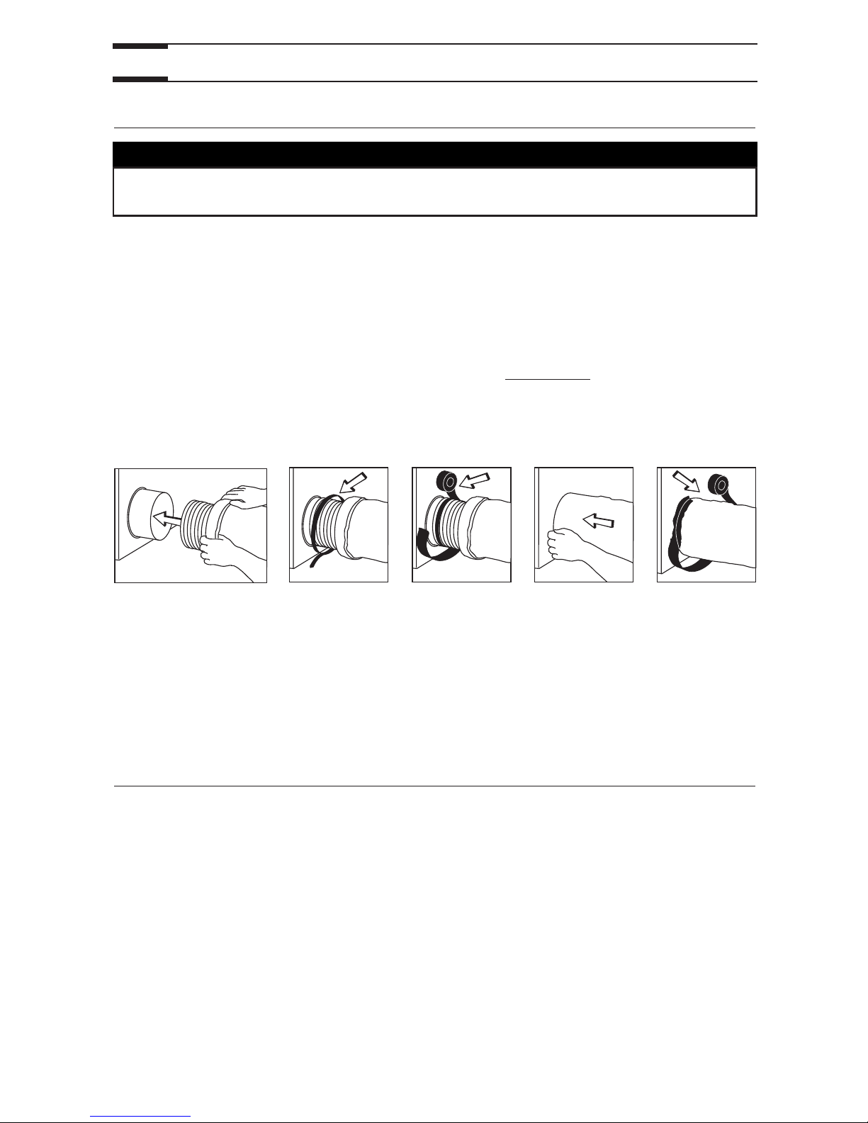
Use the following procedure for connecting the insulated flexible ducts to the unit ports
(exhaust to outside and fresh air from outside).
a) Pull back the insulation to expose the flexible duct.
b) Connect the interior flexible duct to the port using a tie wrap.
c) Carefully seal the connection with duct tape.
d) Pull the insulation over the joint.
e) Apply duct tape to the joint making an airtight seal
. Avoid compressing
the insulation when pulling the tape tightly around the joint; compressed
insulation loses its R value and causes water dripping due to condensation
on the exterior surface of the duct.
a) b) c) d) e)
NOTE: In a retrofit installation, there maybe only one insulated duct already installed for
the unit ports.
• If the unit is installed in the attic, connect this insulated duct to the exhaust to
outside port.
• If the unit is installed in the basement, connect this insulated duct to the fresh
air intake port.
CAUTION
Make sure the vapor barrier on the insulated ducts does not tear during
installation to avoid condensation within the ducts.
3.7.1 TANDEM TRANSITION WITH DUAL EXTERIOR HOOD
VJ0010
Page 12

3. INSTALL THE UNIT (CONT’D)
3.7 EXTERIOR OPENING(S) INSTALLATION (CONT’D)
1. For each duct, pull back the insulation to expose the interior flexible duct.
2. Connect the interior flexible duct to the smaller part of the Tandem transition (5’’ oval)
using a tie wrap.
3. Pull the insulation over the joint. Pull the vapor barrier over the insulation.
4. Apply duct tape gently to the joint in order to make an airtight seal
. See figures below.
VJ0025
VJ0022
VJ0023
VJ0024
1
2
3
4
EXHAUST AIR TO
OUTSIDE DUCT ON
TOP SECTION
12
3.7.1 TANDEM TRANSITION WITH DUAL EXTERIOR HOOD (CONT’D)
CAUTION
Always connect the exhaust air to outside duct on top section of the
Tandem transition.
Dual exterior hood requires assembly. Using 2 no. 8 x 3/4” screws, assemble the top metal
screen and the plastic grille to the dual exterior hood. Then, slide the bottom metal screen to
the dual exterior hood. See illustration below.
VO0024
Page 13

The dual exterior hood must be installed at a minimum
distance of 18 inches (457 mm) from the ground.
See illustration beside.
1. Using a jig saw, cut a 6’’ diameter hole
in the exterior wall and insert the
Tandem transition through this hole.
3. INSTALL THE UNIT (CONT’D)
3.7 EXTERIOR OPENING(S) INSTALLATION (CONT’D)
3.7.1 TANDEM TRANSITION WITH DUAL EXTERIOR HOOD (CONT’D)
VD0083A
18”
(457 mm)
WARNING
Make sure this hood is at least 6 feet (1.8 m) away (or more, as per applicable
building codes or standards) from sources of contamination such as:
• High efficiency furnace vent
• Any exhaust from a combustion source
• Gas meter exhaust, gas barbecue-grill
• Garbage bin
!
VD0084
1
CAUTION
The Tandem transition must be inserted in such a way that the exhaust air
to outside duct will be located on the top.
13
1) Exhaust air to outside duct
Page 14

4. Snap the assembled exterior hood on its
backplate and secure with 2 provided
screws (no. 8 x 3/4” long).
3. Lean the exterior backplate to the exterior
wall. Using 4 no. 8 x 1½” screws, fix it to
the wall. Seal the outline with caulking.
3. INSTALL THE UNIT (CONT’D)
3.7 EXTERIOR OPENING(S) INSTALLATION (CONT’D)
3.7.1 TANDEM TRANSITION WITH DUAL EXTERIOR HOOD (CONT’D)
2. Join the end of the Tandem transition to
the rear of the exterior backplate.
Secure with 2 Xmas tree pins and seal
properly with duct tape.
VD0085
CAUTION
The exterior backplate must be installed with the word “TOP” pointing
upward.
Xmas tree pin
VD0086
VD0087
screw
14
Page 15
3. INSTALL THE UNIT (CONT’D)
3.7 EXTERIOR OPENING(S) INSTALLATION (CONT’D)
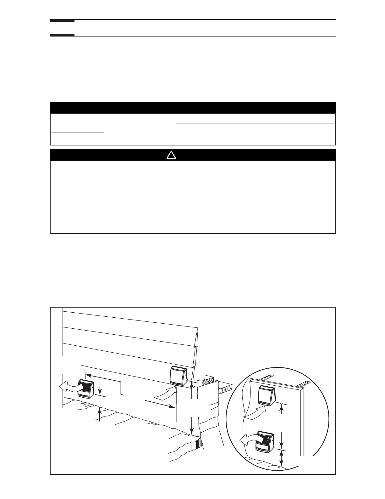
3.7.2 LOCATING 2 EXTERIOR HOODS
If this unit installation needs to have 2 exterior hoods, an additional exterior hood must
be bought (sold separately, single exterior hood, part number 13940). Choose an
appropriate location for installing the exterior hoods.
• The dual exterior hood must be located at a minimum distance of 4 inches
(102 mm) from the ground.
• The single exterior hood must be located at a minimum distance of 18 inches
(457 mm) from the ground.
• There must be a minimum distance of 6 feet (1.8 m) between the hoods to avoid
cross-contamination. See figure below.
15
CAUTION
Due to its particular design, the dual exterior hood must be used only for
exhaust hood when performing an installation using 2 exterior hoods.
Use the single exterior hood for supply air.
VD0094
EXHAUST
HOOD
INTAKE
HOOD
4’’
(102
MM)
6’
1.8
M)
6’
(1.8
M)
18’’
(457
MM)
4’’ (102 MM)
OPTIONAL
LOCATION
WARNING
Make sure the single exterior hood is at least 6 feet (1.8 m) away (or more, as
per applicable building codes or standards) from sources of contamination
such as:
• High efficiency furnace vent
• Any exhaust from a combustion source
• Gas meter exhaust, gas barbecue-grill
• Garbage bin
!
Page 16

3. INSTALL THE UNIT (CONT’D)
3.7 EXTERIOR OPENING(S) INSTALLATION (CONT’D)
3.7.3 CONNECTING INSULATED DUCTS TO 2 EXTERIOR HOODS
1. For each exterior hood, using a jig saw, cut a 6’’ diameter hole in the exterior wall.
Run each flexible duct through its respective hole in the wall.
2. For each exterior hood, pull back the
insulation to expose the flexible duct and,
using a tie wrap, attach it to the inner ring
of the exterior backplate. Carefully seal
with duct tape (A). Pull the insulation over
the joint. Pull the vapor barrier over the
insulation and over the outer ring of the
exterior backplate. Apply gently duct tape
to the joint making an airtight seal (B).
3. Attach the exterior backplate to the exterior
wall. Using four provided screws, fix it to
the wall. Seal the backplate with caulking,
as shown beside.
4. Snap each assembled exterior hood on its respective backplate location and
secure each of them with their 2 provided screws.
16
CAUTION
Make sure the insulated ductwork vapor barrier does not tear during
installation.
CAUTION
The exterior backplate must be installed with the word “TOP” pointing
upward.
A
B
VD0095
VD0096
VD0087
VD0097
SCREW
SCREW
Page 17

3. INSTALL THE UNIT (CONT’D)
3.7 EXTERIOR OPENING(S) INSTALLATION (CONT’D)
3.7.4 LOCATING 2 SOFFIT GRILLES
• Do not locate where prevailing winds
blow the stale air towards the fresh
air vent.
• There must be a minimum distance
of 6 feet (1.8 m) between the grilles
to avoid cross-contamination. See
illustration beside.
17
CAUTION
Make sure the insulated ductwork vapor barrier does not tear during
installation.
3.7.5 CONNECTING INSULATED DUCTS TO 2 SOFFIT GRILLES
1. For each exterior hole, using a jig saw, cut a
4¼’’ diameter hole in the soffit. Pull back the
insulation to expose the flexible duct. Run each
flexible duct through its respective hole.
2. Using provided screws, attach the flexible duct
to the ring of the soffit grille. Carefully seal with
duct tape. Assemble the soffit grilles to the
soffit.
VD0160
6
’
(1
.8
M
)
VI0014
WARNING
Make sure the air intake grille is at least 6 feet (1.8 m) away (or more, as per
applicable building codes or standards) from sources of contamination
such as:
• High efficiency furnace vent
• Any exhaust from a combustion source
• Gas meter exhaust, gas barbecue-grill
• Garbage bin
!
If this unit is installed in the attic, use the installation kit no. EA20130 (not available in the
U.S.A.). Choose an appropriate location for installing the soffit grilles (included in the
installation kit no. EA20130).
Page 18

4. WALL CONTROL
4.1 INSTALLATION OF THE WALL CONTROL
18
WARNING
Always disconnect the unit before making any connections. Failure in
disconnecting power could result in electrical shock or damage of the
wall control or electronic module of the unit.
!
CAUTION
Never install more than one optional wall control per unit.
1. Determine the more convenient location for the control.
2. Remove the cover plate control (1). If you prefer to mount
the wall control on an approved outlet box or an approved
mounting bracket (not included), discard the backplate (2).
3. Take one end of the cable and pass it through the wall control backplate (or outlet box
or mounting bracket).
4. Splice back this end of the cable to access to the 4 wires. Remove the insulated
sleeve of each wire ends. Make a loop with each bare end wire to hook them to their
corresponding screw. Connect YELLOW wire to “Y” screw, RED wire to “R” screw,
GREEN to “G” screw and BLACK to “B” screw. See illustration below.
1
2
WARNING
To avoid risk of electrical shocks, never install another wire in the same
electrical box than the one for the wall control.
!
BLACK
wire
YELLOW
wire
GREEN
wire
RED
wire
WARNING
Make sure that the wires don’t short circuit between themselves or by
touching any other components on the wall control.
!
Page 19

5. Pass the other end of the cable through the wall. Reinstall the cover plate. Using wall
anchors (not included) and provided screws, mount the wall control on the wall. See
illustrations below.
1) Wall anchors 4) Control 1) Outlet box 3) Control
2) Control cable 5) Screws 2) Control cable 4) Screws
3) Control backplate
6. Route the cable to the unit.
7. Remove the electrical box cover on the side of the unit.
8. Slide the sleeve (included) over the cable control and pass the cable through the
grommet.
1) Cable control
2) Sleeve
3) Grommet
4. WALL CONTROL (CONT’D)
4.1 INSTALLATION OF THE WALL CONTROL (CONT’D)
19
VC0052
VC0051
1
2
3
4
5
2
3
4
1
CAUTION
Keep control low voltage wiring at least 1 foot (305 mm) away from
motors, lightning ballast, light dimming circuit and power distribution
panel. Do not route control wiring along with house power wiring. Avoid
poor wiring connections. Failure to follow these practices can introduce
electrical interference, which can cause erratic control operations.
CAUTION
The sleeve must stay in the grommet. See figure below.
VD0157
1 2
3
Page 20

9. Splice back the end of the cable to access
the 4 wires. Remove the insulated sleeve of
each wire ends. Connect each wires in their
corresponding terminal (YELLOW in “Y”,
RED in “R”, GREEN in “G” and BLACK in “B”).
10.Reinstall the electric box cover and plug the unit.
4. WALL CONTROL
4.1 INSTALLATION OF THE WALL CONTROL (CONT’D)
4.2 OPERATING THE WALL CONTROL
20
VE0083
Y
R
G
B
FRESH AIR INDICATOR:
L
IGHTS UP WHEN SLIDE
SWITCH IS ON NORMAL OR
BOOST POSITION.
FILTER MAINTENANCE
INDICATOR:
F
LASHES EVERY SECOND TO
INDICATE IT IS TIME TO
PERFORM BIANNUAL
MAINTENANCE
. SEE SECTION 5.
LIGHTS UP WHEN ITS TIME TO
PERFORM ANNUAL
MAINTENANCE. SEE SECTION 5.
RECIRCULATION:
UNITISOPERATINGON
NORMAL SPEED WITHOUT
EXCHANGING AIR WITH
THE OUTSIDE
.
BOOST:
UNITISOPERATINGON
HIGH SPEED.
RESET FILTER HOLE:
ONCE THE MAINTENANCE DONE, RESET THE FILTER
MAINTENANCE INDICATOR BY CAREFULLY INSERTING
ASMALLROD
(E.G.: PAPER CLIP) IN THE RESET
FILTER HOLE, DURING 1 SECOND. THE FILTER
MAINTENANCE INDICATOR WILL TURN OFF.
NORMAL:
U
NITISOPERATINGON
NORMAL SPEED.
VC0055
Page 21

21
4.2 OPERATING THE WALL CONTROL (CONT’D)
4. WALL CONTROL (CONT’D)
• OFF: To stop the unit, slide the button on this position.
• NORMAL: For a day-to-day usage, slide the button on this position. The
unit then will operate on normal speed.
• B
OOST: For a high speed operation, slide the button on this position.
Generally used when extreme conditions occur, e.g.: parties,
smokers, etc.
• R
ECIRCULATION: For a normal speed operation, without exchanging air with the
outside, slide the button on this position. This mode is
recommended in high humidity days (rain, heat wave). Also,
use it when the outside temperature is extremely cold and/or
the inside air is too dry. It can be used also to recirculate the
heat coming from a wood stove throughout the house, or the
fresh air from a cooling system.
Page 22

22
1. Disconnect the power supply.
2. Clean filter
• Remove filter.
• Vacuum to remove most of the dust.
• Wash with a mixture of warm water
and mild soap. You may add bleach if
you wish to disinfect (one tablespoon
per gallon). Rinse thoroughly. Shake
filter to remove excess water and let dry.
NOTE: Washing the filter in the top tray of the dishwasher is possible, but the aluminum
frame might tarnish.
3. Plug back the unit.
4. Reset the filter maintenance indicator by inserting a small rod (e.g.: paper clip end)
into the reset filter hole of the optional wall control. Press lightly until the Filter
Maintenance indicator light turns off.
5.1 BIANNUAL MAINTENANCE
5. MAINTENANCE
VD0005
WARNING
Risk of electrical shocks. Before performing any maintenance or servicing,
always disconnect the unit from its power source. It is recommended to
wear safety glasses and gloves when performing maintenance or servicing.
!
VO0017
VD0006
Page 23

23
5.2 ANNUAL MAINTENANCE
5. MAINTENANCE (CONT’D)
1. Disconnect the power supply.
2. Clean filter
• Remove filter.
• Vacuum to remove most of the dust.
• Wash with a mixture of warm water and
mild soap. You may add bleach if you
wish to disinfect (one tablespoon per
gallon). Rinse thoroughly. Shake filter to
remove excess water and let dry.
NOTE: Washing the filter in the top tray of the dishwasher is possible, but the aluminum
frame might tarnish.
3. Check the exterior air intake hood
:
• Make sure there are no leaves, twigs, ice or snow that could be drawn into the
vent.
• Clean if necessary.
4. Plug back the unit.
5. Reset the filter maintenance indicator by inserting a small rod (e.g.: paper clip end)
into the reset filter hole of the optional wall control. Press lightly until the Filter
Maintenance indicator light turns off.
VD0005
VD0006
VO0017
CAUTION
Even a partial blocking of this air vent could cause the unit to malfunction.
Page 24

24
5.3 MASTER RESET
5. MAINTENANCE (CONT’D)
Use the master reset only if you perform the annual maintenance before the annual
maintenance indicator is on. By inserting a small rod (e.g.: paper clip end) during 5 seconds
and more into the reset filter hole of the wall control, a master reset will be done and both
biannual and annual maintenance filter are reset.
If the wall control is in Off position, Fresh air light indicator will flash for 1 second.
If the wall control is in Normal or Boost position, the unit motor and the Fresh air light
indicator will turn off for 3 seconds.
If the wall control is in Recirculation position, the unit motor will turn off during 3 seconds.
6. TROUBLESHOOTING
If the problem is still not solved, call your installer or the nearest approved Service
Center.
Also, you can reach the Customer Service Department at the following telephone numbers:
Exclusively for model AE60:
1-800-637-1453.
Exclusively for model EA1500:
1-800-567-3855.
Exclusively for model HV 1.5:
1-866-737-7770.
PROBLEMS SOLUTIONS
1. Unit does not start at Normal
or Boost position.
• Check breaker or fuse in main distribution panel.
• Check there is 120V at the electrical outlet.
2. Unit does not run at Normal
speed, but runs at Boost.
• Check control wiring and wall control connections.
3. Unit is not operating as per
the selected mode.
• Check wall control wiring.
4. Wall control indicators do not
work properly or not at all.
• Check wall control wiring.
5. Air too dry. • Avoid operating the unit on BOOST mode.
• Use the Recirculation mode.
6. Persistant condensation. • Turn on the central heating system.
• Store the firewood outside the house.
• Do not completely close curtains, blinds, etc.
Page 25

AE60 / EA 1500 / HV 1.5
VB0063
Guide d’installation et d’utilisation
Adresse de votre installateur
06095 rév. A
USAGE RÉSIDENTIEL SEULEMENT
INSTALLATEUR : LAISSER CE GUIDE AU PROPRIÉTAIRE.
PROPRIÉTAIRE : INSTRUCTIONS D’UTILISATION ET D’ENTRETIEN
EN PAGES 20 À 24.
LIRE ET CONSERVER CES INSTRUCTIONS
Page 26

2
!
AVERTISSEMENT
AFIN DE RÉDUIRE LES RISQUES D’INCENDIE, D’ÉLECTROCUTION OU DE
BLESSURES CORPORELLES, VEUILLEZ SUIVRE LES INSTRUCTIONS SUIVANTES :
1. Cet appareil a été conçu pour usage résidentiel seulement.
2. N’utilisez cet appareil que de la façon prévue par le manufacturier. Si vous avez des
questions, contactez le manufacturier à l’adresse ou au numéro de téléphone
indiqués dans le texte de la garantie.
3. Avant de remplacer les filtres, de nettoyer ou de réparer l’appareil, débranchez le
cordon d’alimentation de la prise électrique.
4. Les travaux d’installation et de raccordement électrique doivent être effectués par une
personne qualifiée, conformément aux codes et standards de construction, incluant
ceux concernant le feu.
5. Cet appareil n’est pas conçu pour fournir l’air nécessaire à la combustion et/ou à la
dilution des appareils à foyer.
6. Lorsque vous coupez ou perforez un mur ou un plafond, prenez garde de ne pas
endommager les fils électriques ou tout appareil cachés.
7. Ne pas utiliser cet appareil avec une commande de vitesse à semi-conducteur, sauf les
commandes murales C34, CMR et ACCGSC3.
8. Cet appareil doit être mis à la terre. Pour votre propre protection, le cordon d’alimentation
est muni d’une fiche à 3 broches Cette fiche doit être branchée à une prise à 3 trous
avec une mise à la terre, conformément au code national d’électricité ainsi qu’aux
codes et règlements locaux. Ne pas enlever la broche pour la mise à la terre. Ne pas
utiliser de rallonge électrique.
9. Ne pas installer dans une aire de cuisson ou brancher directement à aucun appareil ménager.
10. Ne pas utiliser pour évacuer des matières ou des vapeurs dangereuses ou explosives.
11. Ne pas installer les conduits directement au dessus ou à moins de 2 pi (0,61 m) d’aucune
fournaise, de son conduit de distribution, de chaudière ou d’aucun appareil de
chauffage. Ne raccorder les conduits de l’appareil à aucun conduit de la fournaise
,
autant au plenum de retour d’air qu’à son conduit de distribution.
12. Il est recommandé de porter des lunettes et des gants de sécurité lors de l’installation,
de l’entretien ou de la réparation de cet appareil.
13. Lorsque la législation fédérale, provinciale ou d’un État comporte des exigences
d’installation et/ou de certification plus restrictives, lesdites exigences prévalent sur
celles de ce document et l’installateur entend s’y conformer à ses frais.
ATTENTION
1. Afin d’éviter l’encrassement prématuré des filtres, arrêter le fonctionnement de votre
appareil lors de travaux de construction/rénovation, etc.
2. Pour plus d’informations au sujet de votre appareil, veuillez lire les autocollants
apposés sur et à l’intérieur de votre appareil.
3. S’assurer que les bouches correspondantes donnent à l’extérieur. Ne pas
aspirer ou évacuer l’air dans des espaces restreints comme l’intérieur des murs ou
plafond ou dans le grenier, un vide sanitaire ou un garage.
4. Destiné pour usage résidentiel seulement, selon les prescriptions du NFPA 90B.
5. Le réseau de conduit doit être installé selon tous les codes locaux et nationaux en vigueur.
6. Ne pas utiliser l’échangeur d’air AE60, EA 1500 ou le HV 1.5 lors de travaux de vernissage.
De plus, si l’appareil est situé dans l’entretoit, boucher la grille d’aspiration d’air vicié et
la grille de distribution d’air frais. Les vapeurs de vernis peuvent endommager l’appareil.
7. Les pièces mécaniques et électroniques de l’appareil devraient être inspectées
annuellement par du personnel d’entretien qualifié.
8. Si l’appareil AE60, EA 1500 ou le HV 1.5 est installé dans l’entretoit, l’appareil doit
fonctionner sans arrêt durant l’hiver afin d’éviter la formation de condensation à l’intérieur
de l’appareil et des conduits.
9. Lors de tempête de neige/pluie, faire fonctionner l’appareil en mode recirculation afin
d’empêcher l’infiltration d’eau dans le ventilateur.
Page 27

1. VOTRE APPAREIL ET SON RÔLE . . . . . . . . . . . . . . . . . . . . . . . .4
2. I
NSTALLATIONS TYPIQUES . . . . . . . . . . . . . . . . . . . . . . . . . . . .5
2.1 Installation au sous-sol . . . . . . . . . . . . . . . . . . . . . . . . . . . . . . . . . . . . . . .5
2.2 Installation au grenier . . . . . . . . . . . . . . . . . . . . . . . . . . . . . . . . . . . . . . . .5
2.3 Considérations d’installation . . . . . . . . . . . . . . . . . . . . . . . . . . . . . . . . . . .6
3. INSTALLATION DE L’APPAREIL . . . . . . . . . . . . . . . . . . . . . . . . . .7
3.1 Emplacement et installation de l’appareil . . . . . . . . . . . . . . . . . . . . . . . . .7
3.2 Outils et matériaux
3.3 Comment suspendre l’appareil . . . . . . . . . . . . . . . . . . . . . . . . . . . . . . . .7
3.4 Planification du réseau de conduits . . . . . . . . . . . . . . . . . . . . . . . . . . . . .8
3.5 Installation des conduits de 6 po et des grilles . . . . . . . . . . . . . . . . . .8-10
3.6 Installation des conduits flexibles isolés . . . . . . . . . . . . . . . . . . . . . . . . .11
3.7 Installation de la (des) bouche(s) extérieure(s) . . . . . . . . . . . . . . . .11-17
4. COMMANDE MURALE . . . . . . . . . . . . . . . . . . . . . . . . . . . . . . .18
4.1 Installation de la commande murale . . . . . . . . . . . . . . . . . . . . . . . . .18-20
4.2 Utilisation de la commande murale . . . . . . . . . . . . . . . . . . . . . . . . . .20-21
5. ENTRETIEN . . . . . . . . . . . . . . . . . . . . . . . . . . . . . . . . . . . . .22
5.1 Entretien semestriel . . . . . . . . . . . . . . . . . . . . . . . . . . . . . . . . . . . . . . . .22
5.2 Entretien annuel . . . . . . . . . . . . . . . . . . . . . . . . . . . . . . . . . . . . . . . . . . .23
5.3 Réinitialisation générale . . . . . . . . . . . . . . . . . . . . . . . . . . . . . . . . . . . . .24
6. DÉPANNAGE . . . . . . . . . . . . . . . . . . . . . . . . . . . . . . . . . . . . .24
3
TABLE DES MATIÈRES
Ce guide a été rédigé dans le but de vous aider à installer votre appareil, ainsi qu’à vous
indiquer comment l’utiliser et l’entretenir. Nous vous encourageons à consulter l’ensemble
des sections de ce guide car chacune présente des informations importantes.
Certains détails de votre appareil peuvent différer légèrement de ceux illustrés, les
illustrations qui s’y trouvent sont génériques.
Vos commentaires et suggestions sur ce guide ou votre appareil sont les bienvenus. Ils
nous permettront d’encore mieux vous servir. Faites-nous parvenir le tout à l’adresse
figurant sur la fiche d’enregistrement du produit, laquelle est insérée dans le présent guide.
Ce guide utilise les symboles suivants afin d’accentuer les informations particulières :
NOTE : Indique une information supplémentaire afin de réaliser complètement
une instruction.
En terminant, nous tenons à vous féliciter pour l’achat de cet excellent appareil qui
assurera, à vous et à votre famille, des années d’air frais à l’intérieur de votre demeure.
NOTE : Grâce à son design, l’appareil ne nécesite pas de balancement.
À PROPOS DE CE GUIDE/PRODUIT
AVERTISSEMENT
Identifie une instruction qui, si elle n’est pas suivie, peut causer de graves
blessures personnelles ou la mort.
!
ATTENTION
Identifie une instruction qui, si elle n’est pas suivie, peut gravement
endommager l’appareil et/ou ses pièces.
Page 28

VF0035
PRINCIPES DE FONCTIONNEMENT
4
1. VOTRE APPAREIL ET SON RÔLE
VF0034
CIRCULATION AVEC ÉCHANGE D’AIR :
Tout en faisant circuler l’air dans toute la maison, l’appareil évacue une partie de l’air vicié
et le remplace par de l’air frais et sec provenant de l’extérieur. Les bienfaits suivants sont
ainsi obtenus : évacuation de l’excès d’humidité lors des mois d’hiver, élimination de l’air
vicié, un air ambiant plus confortable durant les chaudes nuits d’été.
L’échangeur d’air est conçu pour éliminer les problèmes d’humidité excessive, pour
uniformiser la température et l’humidité ainsi que pour filtrer et purifier l’air ambiant de la
maison. L’échangeur d’air effectue les opérations suivantes :
RECIRCULATION DE L’AIR :
L’appareil fait circuler l’air à l’intérieur de la maison, sans échange d’air avec l’extérieur.
Ce faisant, il uniformise la température et l’humidité.
FILTRATION :
L’air qui circule dans l’appareil passe au travers d’un filtre mécanique qui capte
ses impuretés.
D
ISTRIBUTION
D’AIR FRAIS
DISTRIBUTION
D
’AIR FILTRÉ
ÉVACUATION
D’AIR VICIÉ
ASPIRATION
D’AIR FRAIS
ASPIRATION
D’AIR VICIÉ
ASPIRATION
D
’AIR VICIÉ
Page 29

5
2. INSTALLATIONS TYPIQUES
Se servir des illustrations ci-dessous comme repères afin de vous aider à choisir
l’installation qui vous conviendra le mieux. L’appareil doit être suspendu aux solives, à
l’aide des chaînes et ressorts (inclus). Si nécessaire, installer l’appareil en position
inversée. Pour plus de détails, voir le point 3.
INSTALLATION DE L’APPAREIL
.
Dans tous les cas, l’utiliser un ventilateur de salle de bains ainsi qu’une hotte de
cuisinière pour évacuer l’air vicié. Aussi, pour les maisons ayant plus d’un étage, installer
une grille d’évacuation d’air vicié à l’étage le plus élevé.
NOTE : Une prise électrique standard à 3 trous avec une mise à la terre doit être accessible
à moins de 3 pieds de l’appareil.
VH0053
Grâce à notre transition Tandem®* et à la bouche
extérieure double* un seul trou est requis dans la paroi
extérieure de la maison, ce qui simplifie l’installation.
Ces deux pièces font partie de la trousse
d’installation n° 15273 (non incluse).
NOTES : 1.Voir le point 2.3
CONSIDÉRATIONS
D’INSTALLATION
en page suivante
pour connaître la distance requise
entre les solives.
2.La trousse d’installation n° 15273 n’est
pas offerte aux É.-U.
*Brevetées.
S’il est installé dans l’entretoit, l’appareil doit
fonctionner continuellement durant l’hiver.
Utiliser la trousse d’installation n° EA20130
(non incluse).
NOTE : La trousse d’installation n° EA20130
n’est pas offerte aux É.-U.
2.1 INSTALLATION AU SOUS-SOL
VH0004
2.2 INSTALLATION DANS L’ENTRETOIT
Page 30

6
2. INSTALLATIONS TYPIQUES (SUITE)
Cet appareil peut être utilisé pour en remplacer un déjà installé. Relier les conduits existants
aux bouches correspondantes de l’appareil. Si les conduits d’origine d’évacuation d’air
vicié et d’aspiration d’air frais sont de 5 po de diamètre, visser les adaptateurs de 5 po
de diamètre (inclus) par dessus les bouches de 4 po de l’appareil. Aussi, installer ces
adaptateurs si les trousses d’installation n
os
15273 ou EA20130 (non offertes aux É.-U.)
sont utilisées. Se servir de 4 vis (incluses) par bouche. Voir l’illustration ci-dessous.
La distance requise entre les solives pour l’installation de la transition Tandem est d’au
moins 9¾ po (248 mm). La hauteur maximale de cette transition Tandem est de 8¾ po
(222 mm). Voir l’illustration ci-dessous.
NOTE : La transition Tandem fait partie de la trousse d’installation n° 15273 (non offerte
aux É.-U.).
2.3 CONSIDÉRATIONS D’INSTALLATION
VJ0030
VD0118F
8¾ po
222 mm
9¾ po
248 mm
Page 31

7
3. INSTALLATION DE L’APPAREIL
Choisir un bon emplacement pour l’appareil, éloigné des pièces où l’on recherche la tranquilité.
• De façon à pouvoir accéder facilement au filtre, pour l’entretien (quelquefois,
en installant l’appareil à l’envers, il est possible de faciliter cet accès).
• Près d’un mur extérieur, afin de limiter la longueur des conduits flexibles isolés.
• Éloigné des cheminées et autres risques d’incendie.
• Prévoir une source d’alimentation électrique (prise standard 3 trous avec
une mise à la terre).
3.1 EMPLACEMENT ET INSTALLATION DE L’APPAREIL
• Un tournevis Phillips n° 2 ou Robertson n° 2
• Des ciseaux ou un couteau (pour couper le ruban adhésif en toile et les
conduits flexibles
• Du ruban adhésif en toile
• Une scie va-et-vient
• Des ciseaux à tôle (si le revêtement de la maison est en aluminium ou en vinyle)
• Un burin et un marteau (si le revêtement extérieur de votre maison est en brique)
• Un pistolet à calfeutrer et du calfeutre
3.2 OUTILS ET MATÉRIAUX
Se servir des 4 chaînes et ressorts inclus dans la boîte de quincaillerie. Selon vos
besoins, l’appareil peut être installé en position inverse.
3.3 COMMENT SUSPENDRE L’APPAREIL
VD0156
ATTENTION
S’assurer que l’appareil est au niveau.
Page 32

8
3. INSTALLATION DE L’APPAREIL (SUITE)
• Prévoir un réseau le plus simple possible, avec un minimum de coudes et de
raccords. La longueur des conduits isolés doit être réduite au minimum.
• Ne pas utiliser de murs creux comme conduits. Ne pas utiliser de conduits de
dérivation plus petits que 4 po (102 mm) de dimètre.
• Ne pas ventiler les vides sanitaires ni les chambres froides. Ne pas essayer
de récupérer l’air évacué d’une sécheuse ou d’une hotte de cuisinière; cela
causerait l’encrassement de l’appareil.
• Si la maison a plus d’un étage, prévoir au moins une grille d’aspiration au
niveau le plus élevé.
3.4 PLANIFICATION DU RÉSEAU DE CONDUITS
• Installer la (les) grille(s) d’évacuation d’air vicié dans les pièces qui génèrent
des polluants : cuisine, salon, etc. La grille doit être le plus éloignée possible
des escaliers, de façon à ce que l’air circule librement dans toutes les
pièces habitées.
• Si une grille est installée dans la cuisine, elle doit être située à au moins
4 pi (1,2 m) au dessus de la cuisinière.
• Installer la (les) grille(s) sur un mur, à une distance de 6 po à 12 po (152 mm
à 305 mm) du plafond OU au plafond.
• Relier une extrémité du conduit flexible de 6 po à la grille d’évacuation d’air
vicié et l’autre extrémité à la bouche d’aspiration d’air vicié, à l’aide de colliers
de serrage et de ruban adhésif en toile.
3.5 INSTALLATION DES CONDUITS DE 6 PO ET DES GRILLES
AVERTISSEMENT
Ne jamais installer une grille d’évacuation dans une pièce où se trouve un
appareil de combustion tel qu’une fournaise, un chauffe-eau à gaz ou un foyer.
!
3.5.1 CONDUIT D’ÉVACUATION D’AIR VICIÉ
• Installer la (les) grille(s) de distribution d’air frais dans une vaste pièce, afin
d’assurer la meilleure circulation d’air possible. Se rappeler que la (les)
grille(s) de distribution d’air frais doivent être le plus éloignée(s) possible de
la (les) grille(s) d’aspiration d’air vicié.
• Installer la (les) grille(s) au plafond OU sur un mur, à une distance de 6 po à
12 po (152 mm à 305 mm) du plafond. La longueur du conduit doit être
d’au moins 15 pi (4,6 m). (L’air frais circulera à travers la partie supérieure de
la pièce et se mélangera avec l’air ambiant avant de descendre au niveau
des occupants.)
• Relier une extrémité du conduit flexible de 6 po à la grille de distribution d’air
frais, et l’autre extrémité à la bouche de distribution d’air frais de l’appareil, à
l’aide de colliers de serrage et de ruban adhésif en toile.
3.5.2 CONDUIT DE DISTRIBUTION D’AIR FRAIS
ATTENTION
Utiliser toujours des conduits isolés (non inclus) si ces conduits doivent
passer où la température ambiante n’est pas tempérée.
Page 33

3. INSTALLATION DE L’APPAREIL (SUITE)
3.5 INSTALLATION DES CONDUITS DE 6 PO ET DES GRILLES (SUITE)
3.5.3 EMPLACEMENTS SUGGÉRÉS DES GRILLES
VA0032
BUNGALOW
Cage d’escalier du sous-sol (A) : Ouverte, latérale.
Une grille d’évacuation d’air vicié (1) au niveau
habité le plus haut de la maison et une grille de
distribution d’air frais (2) au plus bas niveau
habité de la maison.
1
2
A
VA0033
BUNGALOW
Cage d’escalier du sous-sol (A) : Fermée.
Une grille d’évacuation d’air vicié (1) au niveau
habité le plus haut de la maison et une grille de
distribution d’air frais (2) au plus bas niveau
habité de la maison. Utiliser une grille de
plancher pour compenser la fermeture de la
cage d’escalier.
1
2
A
VA0034
BUNGALOW
Cage d’escalier du sous-sol (A) : Ouverte, centrale.
Deux grilles d’évacuation d’air vicié (1) au
niveau habité le plus haut de la maison et une
grille de distribution d’air frais (2) au plus bas
niveau habité de la maison.
2
A
1
9
Page 34

3. INSTALLATION DE L’APPAREIL (SUITE)
3.5 INSTALLATION DES CONDUITS DE 6 PO ET DES GRILLES (SUITE)
3.5.3 EMPLACEMENTS SUGGÉRÉS DES GRILLES (SUITE)
VA0035
MAISON À DEMI-NIVEAUX
Cage d’escalier (A) : Ouverte, centrale.
Deux grilles d’évacuation d’air vicié (1) aux
niveaux les plus élevés de la maison et une
grille de distribution d’air frais (2) au plus bas
niveau habité de la maison.
1
1
2
A
VA0036
COTTAGE
Cage d’escalier (A) : Ouverte.
Deux grilles d’évacuation d’air vicié (1) aux
niveaux les plus élevés de la maison et une
grille de distribution d’air frais (2) au plus bas
niveau habité de la maison.
1
1
2
A
A
VA0037
COTTAGE
Cage d’escalier (A) : Ouverte en partie, fermée
en d’autres endroits (B).
Une grille d’évacuation d’air vicié (1) au niveau
le plus élevé de la maison et une grille de
distribution d’air frais (2) au plus bas niveau
habité de la maison.
Utiliser des grilles de plancher (B) pour
compenser la fermeture de la cage d’escalier.
2
A
B
B
1
10
Page 35

NOTE : Lors de remplacement d’appareil sans changement de conduits, il se peut que
l’installation n’ait qu’un seul conduit isolé pour les bouches de l’appareil.
• Si l’appareil est installé dans l’entretoit, relier ce conduit isolé à la bouche
d’évacuation d’air vicié.
• Si l’appareil est installé dans le sous-sol, relier ce conduit isolé à la bouche
d’aspiration d’air frais.
11
3.6 INSTALLATION DES CONDUITS FLEXIBLES ISOLÉS
3.7 INSTALLATION DE LA (DES) BOUCHE(S) EXTÉRIEURE(S)
Si les solives sont perpendiculaires aux conduits, ou si le raccordement avec la bouche
exérieure est situé dans un endroit restreint, utiliser deux bouches extérieures (ou grilles
de soffite). Pour plus de détails, voir le point 3.7.2 ou le 3.7.4.
Procéder comme suit pour raccorder les conduits flexibles isolés aux bouches de
l’appareil (évacuation d’air vicié et aspiration d’air frais).
a) Tirer sur l’isolant pour exposer le conduit flexible.
b) À l’aide d’un collier de serrage, relier le conduit flexible intérieur à la bouche.
c) Sceller soigneusement le joint avec du ruban adhésif en toile.
d) Tirer l’isolant au-dessus du joint.
e) Recouvrir le joint de ruban adhésif en toile jusqu’à étanchéité complète
.
Éviter de comprimer l’isolant lors du serrage du ruban autour du joint. Un
isolant comprimé perd sa valeur « R » et provoque aussi la formation de
condensation sur la surface extérieure du conduit.
a) b) c) d) e)
ATTENTION
S’assurer que le coupe-vapeur des conduits isolés ne se déchire pas
durant l’installation afin d’éviter la condensation à l’intérieur des conduits.
3.7.1 TRANSITION TANDEM AVEC LA BOUCHE EXTÉRIEURE DOUBLE
VJ0010
3. INSTALLATION DE L’APPAREIL (SUITE)
Page 36

3. INSTALLATION DE L’APPAREIL (SUITE)
3.7 INSTALLATION DE LA (DES) BOUCHE(S) EXTÉRIEURE(S) (SUITE)
1. Pour chaque conduit, tirer sur l’isolant pour exposer le conduit flexible.
2. À l’aide d’un collier de serrage, relier le conduit flexible intérieur à la partie la plus petite
de la transition Tandem (5 po ovale).
3. Tirer l’isolant par-dessus le joint. Tirer le coupe-vapeur par-dessus l’isolant.
4. Recouvrir doucement le joint de ruban adhésif en toile jusqu’à étanchéité complète
.
Voir les figures ci-dessous.
VJ0025
VJ0022
VJ0023
VJ0024
1
2
3
4
CONDUIT D’ÉVACUATION
D’AIR VICIÉ À LA
SECTION SUPÉRIEURE
12
3.7.1 TRANSITION TANDEM AVEC LA BOUCHE EXTÉRIEURE DOUBLE (SUITE)
ATTENTION
Toujours relier le conduit d’évacuation d’air vicié à la section supérieure
de la transition Tandem.
La bouche extérieure double est en pièces détachées. À l’aide des 2 vis n° 8 x 3/4 po,
assembler le grillage métallique supérieur et la grille de plastique à la bouche extérieure
double. Puis, glisser le grillage métallique inférieur à la bouche extérieure double.
Voir l’illustration ci-dessous.
VO0024
Page 37

La bouche extérieure double doit être installée à une
distance minimum de 18 po (457 mm) du sol.
Voir l’illustration ci-contre.
1. À l’aide d’une scie va-et-vient, faire un trou
de 6 po de diamètre dans le mur extérieur
et y insérer la transition Tandem.
3. INSTALLATION DE L’APPAREIL (SUITE)
3.7 INSTALLATION DE LA (DES) BOUCHE(S) EXTÉRIEURE(S) (SUITE)
3.7.1 TRANSITION TANDEM AVEC LA BOUCHE EXTÉRIEURE DOUBLE (SUITE)
VD0083F
18 po
(457 mm)
AVERTISSEMENT
S’assurer que la bouche est à une distance d’au moins 6 pi (1,8 m) (ou
plus, selon les codes et standards du bâtiment en vigueur) des sources
de contamination telles que :
• Sortie de fournaise haut-rendement
• Sortie de toute source de combustion
• Sortie de compteur de gaz, barbecue à gaz
• Poubelle
!
VD0084
1
ATTENTION
La transition Tandem doit être insérée de façon telle que le conduit
d’évacuation d’air vicié sera situé sur le dessus.
13
1) Conduit d’évacuation d’air vicié
Page 38

3. INSTALLATION DE L’APPAREIL (SUITE)
3.7 INSTALLATION DE LA (DES) BOUCHE(S) EXTÉRIEURE(S) (SUITE)
3.7.1 TRANSITION TANDEM AVEC LA BOUCHE EXTÉRIEURE DOUBLE (SUITE)
2. Relier l’extrémité de la transition
Tandem à l’arrière de la plaque de
bouche extérieure. Fixer à l’aide de
2 goupilles de retenue et sceller
soigneusement avec du ruban adhésif
en toile.
3. Appuyer la plaque de la bouche
extérieure au mur. À l’aide des 4 vis
n° 8 x 1/2 po, la fixer au mur. Sceller le
contour avec du calfeutre.
4. Appuyer la bouche extérieure double
assemblée sur sa plaque et la visser avec
2 vis n° 8 x 3/4 po.
VD0085
ATTENTION
La plaque de bouche extérieure doit être installée de façon telle que le mot
« TOP » se retrouve en haut.
GOUPILLE DE RETENUE
VD0086
VD0087
VIS
14
Page 39

3. INSTALLATION DE L’APPAREIL (SUITE)
3.7 INSTALLATION DE LA (DES) BOUCHE(S) EXTÉRIEURE(S) (SUITE)
3.7.2 EMPLACEMENT DES 2 BOUCHES EXTÉRIEURES
Si l’installation de l’appareil doit être faite avec 2 bouches extérieures, se procurer une
bouche extérieure additionnelle (bouche extérieure simple vendue séparément; numéro
de pièce 13940). Choisir un endroit approprié pour l’installation des bouches extérieures.
• La bouche extérieure double doit être située à au moins 4 pouces (102 mm) du sol.
• La bouche extérieure simple doit être située à au moins 18 pouces (457 mm) du sol.
• Il doit y avoir une distance minimale de 6 pieds (1,8 m) entre les bouches pour
éviter toute contamination. Voir l’illustration ci-dessous.
15
ATTENTION
Vu son design particulier, la bouche extérieure double doit être utilisée
uniquement comme sortie d’air vicié lors d’une installation utilisant
2 bouches extérieures. Se servir de la bouche extérieure simple pour
l’entrée d’air frais.
VD0094
SORTIE
D’AIR VICIÉ
4 PO
(102 MM)
6 PI
(1,8 M)
6 PI
(1,8 M)
18 PO
(457 MM)
4 PO (102 MM)
EMPLACEMENT
ALTERNATIF
ENTRÉE
D
’AIR FRAIS
AVERTISSEMENT
S’assurer que la bouche extérieure simple est à une distance d’au moins
6 pi (1,8 m) (ou plus, selon les codes et standards du bâtiment en vigueur)
des sources de contamination telles que :
• Sortie de fournaise haut-rendement
• Sortie de toute source de combustion
• Sortie de compteur de gaz, barbecue à gaz
• Poubelle
!
Page 40

3. INSTALLATION DE L’APPAREIL (SUITE)
3.7 INSTALLATION DE LA (DES) BOUCHE(S) EXTÉRIEURE(S) (SUITE)
3.7.3 RACCORDEMENT DES CONDUITS ISOLÉS AUX 2 BOUCHES EXTÉRIEURES
1. À l’aide d’une scie va-et-vient, faire un trou de 6 po de diamètre dans le mur
extérieur pour chaque bouche extérieure. Passer chacun des conduits flexibles
à travers leur trou respectif.
2. Pour chaque bouche extérieure, tirer sur
l’isolant pour exposer le conduit flexible, et à
l’aide d’un collier de serrage, relier le conduit
à l’anneau intérieur de la plaque de la bouche
extérieure. Sceller soigneusement le joint
avec du ruban à conduit (A). Tirer l’isolant
au-dessus du joint. Tirer le coupe-vapeur
par-dessus l’isolant et par-dessus l’anneau
extérieur de la plaque de la bouche
extérieure. Recouvrir soigneusement le joint
avec du ruban à conduit, jusqu’à
étanchéité complète (B).
3. Appuyer la plaque de la bouche extérieure
au mur. À l’aide des 4 vis incluses, la fixer
au mur. Sceller le contour avec du calfeutre.
4. Appuyer les 2 bouches extérieures assemblées sur leur plaque respective et les
visser à l’aide de leurs 2 vis fournies.
16
ATTENTION
S’assurer que le coupe-vapeur des conduits isolés ne se déchire pas
durant l’installation.
ATTENTION
La plaque de bouche extérieure doit être installée de façon telle que le mot
« TOP » se retrouve en haut.
A
B
VD0095
VD0096
VD0097
VIS
VD0087
VIS
Page 41

3. INSTALLATION DE L’APPAREIL (SUITE)
3.7 INSTALLATION DE LA (DES) BOUCHE(S) EXTÉRIEURE(S) (SUITE)
3.7.4 EMPLACEMENT DES 2 GRILLES DE SOFFITE
• Les vents dominants ne doivent pas
diriger le flux d’air vicié vers la grille
d’aspiration d’air frais.
• Il doit y avoir une distance minimale
de 6 pieds (1,8 m) entre les grilles
afin d’éviter toute contamination. Voir
l’illustration ci-contre.
17
ATTENTION
S’assurer que le coupe-vapeur des conduits isolés ne se déchire pas
durant l’installation.
3.7.5 RACCORDEMENT DES CONDUITS ISOLÉS AUX 2 GRILLES DE SOFFITE
1. À l’aide d’une scie va-et-vient, faire deux trous
de 4¼ po de diamètre dans le soffite. Tirer sur
l’isolant pour exposer le conduit flexible et
passer chacun des conduits flexibles à travers
leur trou respectif.
2. À l’aide des vis fournies, assembler le conduit
flexible à l’anneau de la grille de soffite. Sceller
soigneusement l’aide de ruban adhésif en
toile. Assembler les grilles au soffite.
VD0160
6
P
I
(
1
,8
M
)
VI0014
AVERTISSEMENT
S’assurer que la grille d’aspiration est à une distance d’au moins
6 pi (1,8 m) (ou plus, selon les codes et standards du bâtiment en vigueur)
des sources de contamination telles que :
• Sortie de fournaise haut-rendement
• Sortie de toute source de combustion
• Sortie de compteur de gaz, barbecue à gaz
• Poubelle
!
Utiliser la trousse d’installation EA20130 si l’appareil est installé dans l’entretoit. Situer
adéquatement les 2 grilles de soffite (incluses dans la trousse d’installation EA20130).
Page 42

4. COMMANDE MURALE
4.1 INSTALLATION DE LA COMMANDE MURALE
18
AVERTISSEMENT
Toujours débrancher l’appareil avant d’effectuer toutes connexions. Le
fait de ne pas débrancher l’appareil pourrait créer un choc électrique,
endommager l’appareil, endommager la commande murale ou le module
électronique à l’intérieur de l’appareil.
!
ATTENTION
Ne jamais installer plus d’une commande murale par appareil.
1. Déterminer l’emplacement de la commande murale le plus commode pour vous.
2. Retirer la plaque (1) de la commande murale. Si vous
désirez installer votre commande à même une boîte de
raccordement ou plaque de fixation approuvée (non incluse),
jeter la plaque arrière (2).
3. Prendre un bout du fil et le passer à travers la plaque arrière de la commande (ou
dans la boîte de raccordement ou la plaque de fixation).
4. Dégainer le fil de la commande pour accéder aux 4 fils. Retirer la gaine des 4 bouts
de fils. À chacun des fils, faire une boucle avec la partie dénudée et les relier à leur
vis correspondante. Brancher le fil JAUNE à la vis « Y », le fil ROUGE à la vis « R »,
le fil VERT à la vis « G » et le fil NOIR à la vis « B ». Voir l’illustration ci-dessous.
1
2
AVERTISSEMENT
Afin d’éviter les chocs électriques, ne jamais installer, dans la même boîte
de raccordement, un autre fil que celui de la commande murale.
!
fil
NOIR
fil
JAUNE
fil
VERT
fil
ROUGE
AVERTISSEMENT
S’assurer qu’il n’y ait aucun court-circuit entre les fils ou entre les fils et
une autre composante de la commande murale.
!
Page 43

5. Passer l’autre bout du fil à travers le mur. À l’aide d’ancrages de gypse (non inclus)
et des vis fournies, installer la commande au mur. Voir les illustrations ci-dessous.
1) Ancrages de gypse 4) Commande 1) Boîte de raccordement 3) Commande
2) Fil de la commande 5) Vis 2) Fil de la commande 4) Vis
3) Plaque arrière
6. Acheminer le fil à l’appareil.
7. Enlever le couvercle du boîtier électrique sur le côté de l’appareil.
8. Glisser la gaine (incluse) sur le fil de la commande et l’insérer dans le passe-fils.
1) Fil de la commande
2) Gaine
3) Passe-fils
4. COMMANDE MURALE (SUITE)
4.1 INSTALLATION DE LA COMMANDE MURALE (SUITE)
19
VC0052
VC0051
1
2
3
4
5
2
3
4
1
ATTENTION
Tenir le câblage basse tension de la commande à une distance d’au moins
1 pi (305 mm) des moteurs, ballast d’éclairage, circuit gradateur
d’éclairage et panneau de distribution de courant. Ne pas faire cheminer le
fil de la commande murale le long du cablâge électrique de la maison.
Éviter les connexions relâchées. Ne pas tenir compte de ces pratiques peut
causer de l’interférence électrique, ce qui peut entraîner le fonctionnement
erratique de la commande murale.
ATTENTION
La gaine doit demeurer dans le passe-fils. Voir l’illustration ci-dessous.
VD0157
1 2
3
Page 44

9. Dégainer le bout du fil pour accéder aux
4 fils. Dénuder le bout de chacun des 4 fils.
Brancher chaque fil à son bornier correspondant
(le fil JAUNE au bornier « Y », le fil rouge au
bornier « R », le fil vert au bornier « G » et le
NOIR au bornier « B »).
10. Réinstaller le couvercle du boîtier électrique et brancher l’appareil.
4. COMMANDE MURALE
4.1 INSTALLATION DE LA COMMANDE MURALE (SUITE)
4.2 UTILISATION DE LA COMMANDE MURALE
20
VE0083
Y
R
G
B
TÉMOIN LUMINEUX «FRESH AIR » :
S’
ALLUME LORSQUE
L’INTERRUPTEUR À GLISSIÈRE
EST EN POSITION «NORMAL »
OU «BOOST ».
TÉMOIN LUMINEUX
«FILTER MAINTENANCE » :
C
LIGNOTE LORSQU’IL EST
TEMPS D’EFFECTUER
L’ENTRETIEN BI-ANNUEL
VOIR LA SECTION 5.
S’
ALLUME LORSQU’IL EST
TEMPS D’EFFECTUER
L’ENTRETIEN ANNUEL.
VOIR LA SECTION 5.
RECIRCULATION :
L’ APPAREIL FONCTIONNE
EN VITESSE NORMALE
SANS ÉCHANGE D
’AIR
AVEC L’EXTÉRIEUR.
BOOST :
L’ APPAREIL FONCTIONNE
EN HAUTE VITESSE
.
TROU POUR LA MISE À ZÉRO «RESET FILTER » :
U
NE FOIS L’ENTRETIEN TERMINÉ, EFFECTUER LA MISE À ZÉRO
DU TÉMOIN LUMINEUX DE L’ENTRETIEN DU FILTRE
(« FILTER MAINTENANCE ») EN INSÉRANT DOUCEMENT UNE
PETITE TIGE
(EX. : TROMBONE) DANS LE TROU POUR LA MISE
À ZÉRO, DURANT 1 SECONDE. LE TÉMOIN LUMINEUX DE
L’ENTRETIEN DU FILTRE S’ÉTEINDRA.
NORMAL :
L’
APPAREIL FONCTIONNE
EN VITESSE NORMALE.
Page 45

21
4.2 UTILISATION DE LA COMMANDE MURALE (SUITE)
4. COMMANDE MURALE (SUITE)
• OFF : Glisser le bouton sur cette position pour arrêter le fonctionnement
de l’appareil.
• NORMAL : Glisser le bouton sur cette position pour un fonctionnement en
vitesse normale, c’est à dire la majorité du temps.
• B
OOST : Glisser le bouton sur cette position pour un fonctionnement en
vitesse maximale, c’est à dire lors de conditions extrêmes
momentanées telles que partys, présence de fumeurs, etc.
• R
ECIRCULATION : Glisser le bouton sur cette position pour un fonctionnement en
vitesse normale, sans échange d’air avec l’extérieur. Ce mode
est recommandé par temps très humide (pluie, vague de
chaleur). Aussi, l’utiliser lorsque l’air intérieur est trop sec, ou
lorsque la température extérieure est très froide. On peut aussi
s’en servir pour recirculer la chaleur d’un poêle à bois à travers
toute la maison, ou bien l’air frais provenant d’un système
de climatisation.
Page 46

22
1
. Débrancher l’appareil.
2. Nettoyer le filtre
.
• Retirer le filtre.
• Passer l’aspirateur pour y enlever la
plus grande partie des poussières.
• Laver dans une solution d’eau chaude
et de savon doux. De l’eau de Javel
peut être ajoutée, si désiré (1 cuillerée
à table par gallon). Rincer à fond.
Secouer le filtre pour retirer l’excédent
d’eau et laisser égoutter.
NOTE : Il est possible de laver ce filtre au lave-vaisselle, dans le plateau du haut.
Cependant, le cadre d’aluminium risque de ternir.
3. Rebrancher l’appareil.
4. Réinitialiser l’indicateur d’entretien des filtres en insérant une petite tige (ex. : trombone)
à l’intérieur du trou de remise à zéro du filtre de la commande murale. Presser
délicatement jusqu’à ce que le témoin lumineux de l’entretien du filtre s’éteigne.
5.1 ENTRETIEN BI-ANNUEL
5. ENTRETIEN
AVERTISSEMENT
Risque de chocs électriques. Débranchez toujours l’appareil avant
d’entreprendre des travaux d’entretien ou de réparation. Il est recommandé
de porter des lunettes et des gants de sécurité lors de l’entretien ou du
nettoyage de l’appareil.
!
VD0005
VO0017
VD0006
Page 47

23
5.2 ENTRETIEN ANNUEL
5. ENTRETIEN (SUITE)
1. Débrancher l’appareil.
2. Nettoyer le filtre
.
• Retirer le filtre.
• Passer l’aspirateur pour y enlever la
plus grande partie des poussières.
• Laver dans une solution d’eau chaude
et de savon doux. De l’eau de Javel
peut être ajoutée, si désiré (1 cuillerée
à table par gallon). Rincer à fond.
Secouer le filtre pour retirer l’excédent
d’eau et laisser égoutter.
NOTE : Il est possible de laver ce filtre au lave-vaisselle, dans le plateau du haut.
Cependant, le cadre d’aluminium risque de ternir.
3. Vérifier la bouche extérieure d’entrée d’air frais
:
• S’assurer qu’il n’y ait pas de feuille, de brindilles, de glace ou de neige qui
pourraient être aspirées dans l’appareil.
• Nettoyer au besoin.
4. Rebrancher l’appareil.
5. Réinitialiser l’indicateur d’entretien du filtre en insérant une petite tige (ex. : trombone)
à l’intérieur du trou de remise à zéro du filtre de la commande murale. Presser
délicatement jusqu’à ce que le témoin lumineux de l’entretien du filtre s’éteigne.
VD0005
VO0017
ATTENTION
Une prise d’air, même partiellement bouchée, peut entraîner un mauvais
fonctionnement de l’appareil.
VD0006
Page 48

24
5.3 RÉINITIALISATION GÉNÉRALE
5. ENTRETIEN (SUITE)
Se servir de la réinitialisation générale seulement dans le cas où l’entretien annuel aurait
été fait avant que le témoin de l’entretien annuel ne se soit allumé. En insérant une petite tige
(ex. : trombone) durant 5 secondes et plus à l’intérieur du trou de remise à zéro du filtre de
la commande murale, une réinitialisation générale s’effectuera et les 2 entretiens de filtre
(bi-annuel et annuel) seront mis à zéro.
Si le bouton de la commande murale est en position « Off », le témoin lumineux
« Fresh air » s’allumera durant 1 seconde.
Si le bouton de la commande murale est en position « Normal » ou « Boost », le moteur
de l’appareil ainsi que le témoin lumineux « Fresh air » s’éteindront durant 3 secondes.
Si le bouton de la commande murale est en position Recirculation, le moteur de
l’appareil s’arrêtera durant 3 secondes.
6. DÉPANNAGE
Si le problème persiste, contacter votre installateur ou le Centre de service approuvé le
plus près de chez vous.
Vous pouvez aussi joindre le département de Service à la clientèle aux numéros de
téléphone suivants :
Exclusivement pour le modèle AE60 :
1 800 637-1453.
Exclusivement pour le modèle EA1500 :
1 800 567-3855.
Exclusivement pour le modèle HV 1.5 :
1 866 737-7770.
PROBLÈMES SOLUTIONS
1. L’appareil ne fonctionne pas en
vitesse « Normal » ou « Boost ».
• Vérifier le fusible et le disjoncteur au panneau
de distribution.
• Vérifier la présence de 120V à la prise électrique.
2. L’appareil ne fonctionne pas
en vitesse « Normal », mais
fonctionne en « Boost ».
• Vérifier le branchement et les connexions de la
commande murale.
3. L’appareil ne fonctionne pas
selon le mode sélectionné.
• Vérifier le branchement de la commande murale.
4. Les témoins lumineux de la
commande murale ne fonctionnent
pas bien ou pas du tout.
• Vérifier le branchement de la commande murale.
5. Air trop sec. • Éviter de faire fonctionner l’appareil en
mode « BOOST ».
• Utiliser le mode Recirculation.
6. Condensation persistante. • Faire fonctionner le chauffage de la maison.
• Ranger le bois de chauffage à l’extérieur.
• Laisser les rideaux, stores, etc. entrouverts.
 Loading...